

Page 1
Installation and
Maintenance
Limited One Year Warranty
T&S warrants to the original purchaser (other
than for purposes of resale) that such product is
free from defects in material and workmanship
for a period of one (1) year from the date of
purchase. During this one-year warranty period,
if the product is found to be defective, T&S shall,
at its options, repair and/or replace it. To obtain
warranty service, products must be returned
to...
T&S Brass and Bronze Works, Inc.
Attn: Warranty Repair Department
2 Saddleback Cove
Travelers Rest, SC 29690
Shipping, freight, insurance, and other
transportation charges of the product to T&S
and the return of repaired or replaced product
to the purchaser are the responsibility of the
purchaser. Repair and/or replacement shall be
made within a reasonable time after receipt by
T&S of the returned product. This warranty does
not cover Items which have received secondary
fi nishing or have been altered or modifi ed after
purchase, or for defects caused by physical
abuse to or misuse of the product, or shipment
of the products.
Any express warranty not provided herein, and
any remedy for Breach of Contract which might
arise, is hereby excluded and disclaimed. Any
implied warranties of merchantability or fi tness
for a particular purpose are limited to one year in
duration. Under no circumstances shall T&S be
liable for loss of use or any special consequential
costs, expenses or damages.
Some states do not allow limitations on how
long and implied warranty lasts or the exclusion
or limitation of incidental or consequential damages, so the above limitations or exclusions may
not apply to you. Specifi c rights under this war-
ranty and other rights vary from state to state.
Instructions
METERING BARREL
ASSEMBLY
P/N: 098-014733-45 Rev.1
Date: 05-18-10
Drawn: TEH
Checked: GEF 09-13-10
Approved: JHB 09-13-10
Page 2
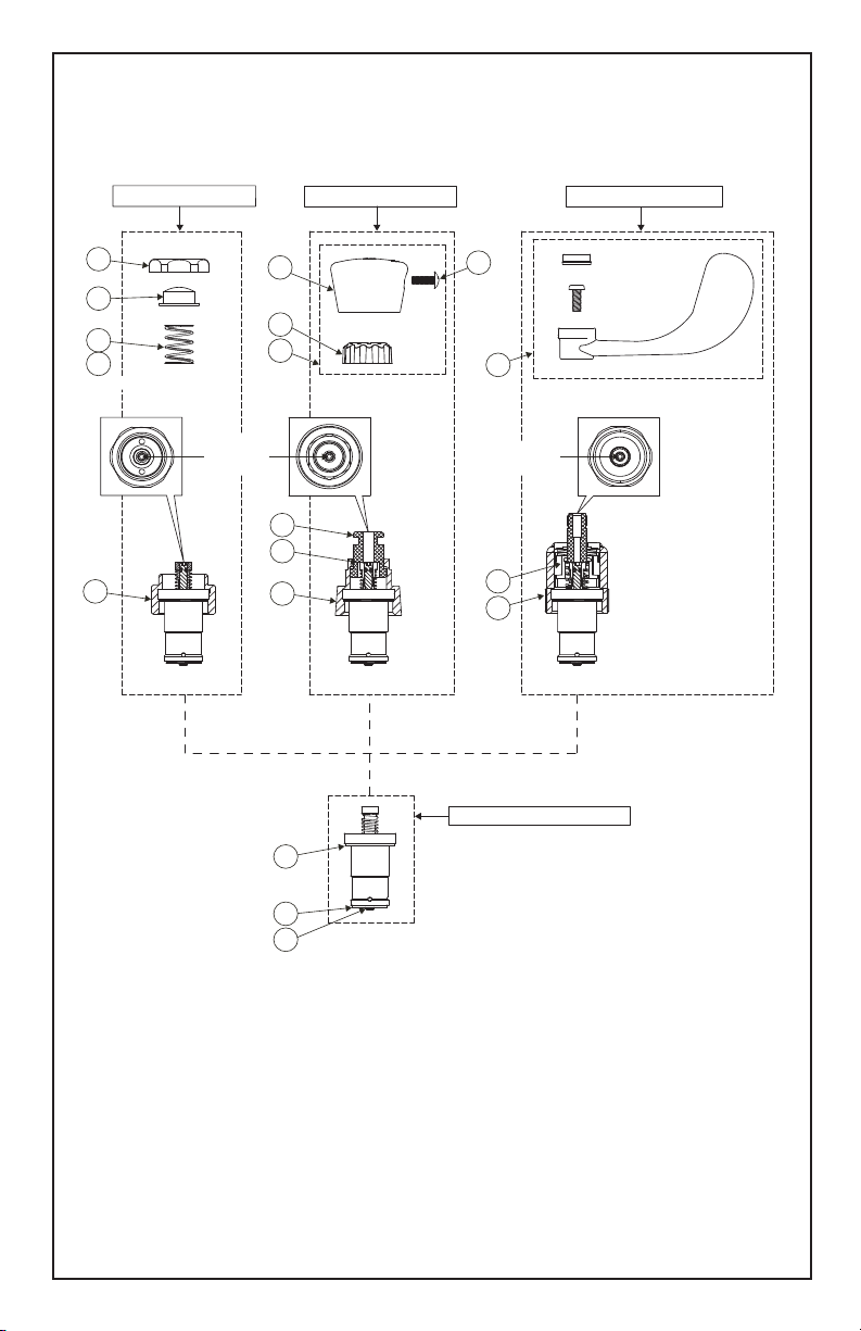
Exploded View
F1-FOOT PEDAL ASM P1-PUSH BUTTON ASM W1-WRIST ACTION ASM
F2
F3
F4
F5
(NOT SHOWN)
F6
METERING
SCREW
P4
P5
P2
P6
P7
P8
C3
P3
W2
METERING
SCREW
W3
W4
C1- METERING BARREL ASM
(HANDLE TYPE MAY VARY)
C4
C5
Page 3

Part Number Guide
Foot Pedal
F1 Asm, Floor Mounted Foot Pedal 011399-40
F2 Screw Cap, Foot Pedal *
F3 Button, Foot Pedal *
F4 Spring *
F6 Bonnet, Foot Pedal *
F1 Asm, Wall Mounted Foot Pedal 011406-40
F2 Screw Cap, Foot Pedal *
F3 Button, Foot Pedal *
F4 Spring *
F5 Spring (011406-40 Asm Not Shown) *
F6 Bonnet, Foot Pedal *
Push Button
P1 Push Button Asm, Blank Valve 238AB
Screw Cap, Foot Pedal 238AH
Button, Foot Pedal 238AC
P2 Blank Cap Asm, Push Button 014193-40
Hot Cap Asm, Push Button 014194-40
Cold Cap Asm, Push Button 014195-45
P3 Screw Cap, Push Button 014145-45
P4 Blank Cap, Push Button *
Hot Cap, Push Button *
Cold Cap, Push Button *
P5 Insulator, Push Button *
P6 Guide Bushing, Push Button *
P7 Kapton Washer (Not Shown) *
P8 Bonnet, Push Button *
Wrist Action
W1 Wrist Action Asm 012449-40
W2 Handle Asm (Various Options Available) *
W3 Repair Kit, Wrist Action 012555-40
Return Spring *
Kapton Washer *
Asm, Stem Cam *
Linear Cam *
Bellville Springs *
Stem Bushing *
W2 Bonnett *
Metering Barrel Assembly
C1 Metering Barrel Assembly 014152-40
C2 Seal Repair Kit 014152-40K
C3 Top Seal *
C4 Bottom Seal *
C5 Stem Seal *
* Items not sold as separate parts; listed for instruction purposes only.
Page 4

General Instructions
Tools Required:
Foot Pedal
1 Allen Wrench (3/32”)
1 1-1/4 Wrench
1 1-3/8 Wrench
Push Button
1 Allen Wrench (3/32”)
1 15/16 Wrench
1 #8 Spanner Bit/Wrench
Wrist Action
1 Allen Wrench (3/32”)
1 1-3/8 Wrench
Metering Cartridge:
Note: Each metering cartridge is
preset for approximately 10 seconds
at the factory. They may be reset at
installation. If water pressure varies,
the cycle time will also vary. T&S
advises to fl ush the supply lines prior
to new faucet or replacement part
installation.
Adjustment
1. Handle/Cap Removal
Foot Pedal: Unscrew screw cap (F2)
from assembly. Remove F3 and F4
(and F5 if installed).
Push Button: Unscrew P3 from cap.
Remove P4.
Wrist Action: Remove W2. Various
handle assemblies are available.
Majority of handle assemblies
contain handle, screw, and index tab.
2. Timing Adjustment
1/8 turn increments
clockwise for longer
fl ow time
1/8 turn increments
counter-clockwise for
shorter fl ow time
Refer to exploded view for metering
screw location.
Depress stem (with P5 insulator installed)
fully to verify timing and make adjustments
if necessary after valve has closed.
3. Reinstall handle assembly
Cartridge Replacement:
1. Turn off water supply.
2. Perform step 1 in adjustment
section.
3. Unscrew F6 (foot pedal), P8
(push button), or W4 (wrist action)
from faucet body.
4. Unscrew C1 from F6, P8, or W4.
Note: Cartridge may have unscrewed
from bonnet during bonnet removal.
5. Discard old C1 and its attached
seals.
6. Screw new C1 into bonnet (F6,
P8, or W4).
7. Verify that external seals are
intact (C3, C4, C5). It is helpful to
push C3 into bonnet until it bottoms
out. This will insure proper sealing
with the faucet body.
8. Screw assembly securely (30 ftlbs minimum) into faucet body.
9. Turn on water supply and check
for leaks.
10. Reinstall handle assembly.
Caution: If faucet has separate hot
and cold controls, make certain that
hot water shuts off before cold to
avoid scalding.
Wrist Action Note: Install wrist
action handles in an orientation that
allows ¼ turn (full activation of
metering cartridge). Whenever
possible, install handles to prevent
valves from being intentionally stuck
in open position when handle is
rotated beyond intended 90° (1/4
turn) activation.
Page 5

RELATED T&S BRASS PRODUCT LINE
T&S BRASS AND BRONZE WORKS, INC.
A fi rm commitment to application-engineered plumbing products
2 Saddleback Cove, P.O. Box 1088, T & S Brass-Europe
Travelers Rest, SC 29690 ‘De Veenhoeve’
Phone: (864) 834-4102 Oude Nieuwveenseweg 84
Fax: (864) 834-3518 2441 CW Nieuwveen
E-mail:
tsbrass@tsbrass.com The Netherlands
 Loading...