

Page 1
Limited One Year Warranty
(Commercial Applications)
T&S warrants to the original purchaser (other
than for purposes of resale) that such product is
free from defects in material and workmanship for
a period of one (1) year from the date of purchase.
During this one-year warranty period, if the product
is found to be defective, T&S shall, at its options,
repair and/or replace it. To obtain warranty service,
products must be returned to...
T&S Brass and Bronze Works, Inc.
Attn: Warranty Repair Department
2 Saddleback Cove
Travelers Rest, SC 29690
Shipping, freight, insurance, and other
transportation charges of the product to T&S and
the return of repaired or replaced product to the
purchaser are the responsibility of the purchaser.
Repair and/or replacement shall be made within a
reasonable time after receipt by T&S of the returned
product. This warranty does not cover Items which
have received secondary fi nishing or have been
altered or modifi ed after purchase, or for defects
caused by physical abuse to or misuse of the
product, or shipment of the products.
Any express warranty not provided herein, and
any remedy for Breach of Contract which might
arise, is hereby excluded and disclaimed. Any
implied warranties of merchantability or fi tness
for a particular purpose are limited to one year in
duration. Under no circumstances shall T&S be
liable for loss of use or any special consequential
costs, expenses or damages.
Some states do not allow limitations on how
long and implied warranty lasts or the exclusion or
limitation of incidental or consequential damages,
so the above limitations or exclusions may not apply
to you. Specifi c rights under this warranty and other
rights vary from state to state.
Installation and
Maintenance
Instructions
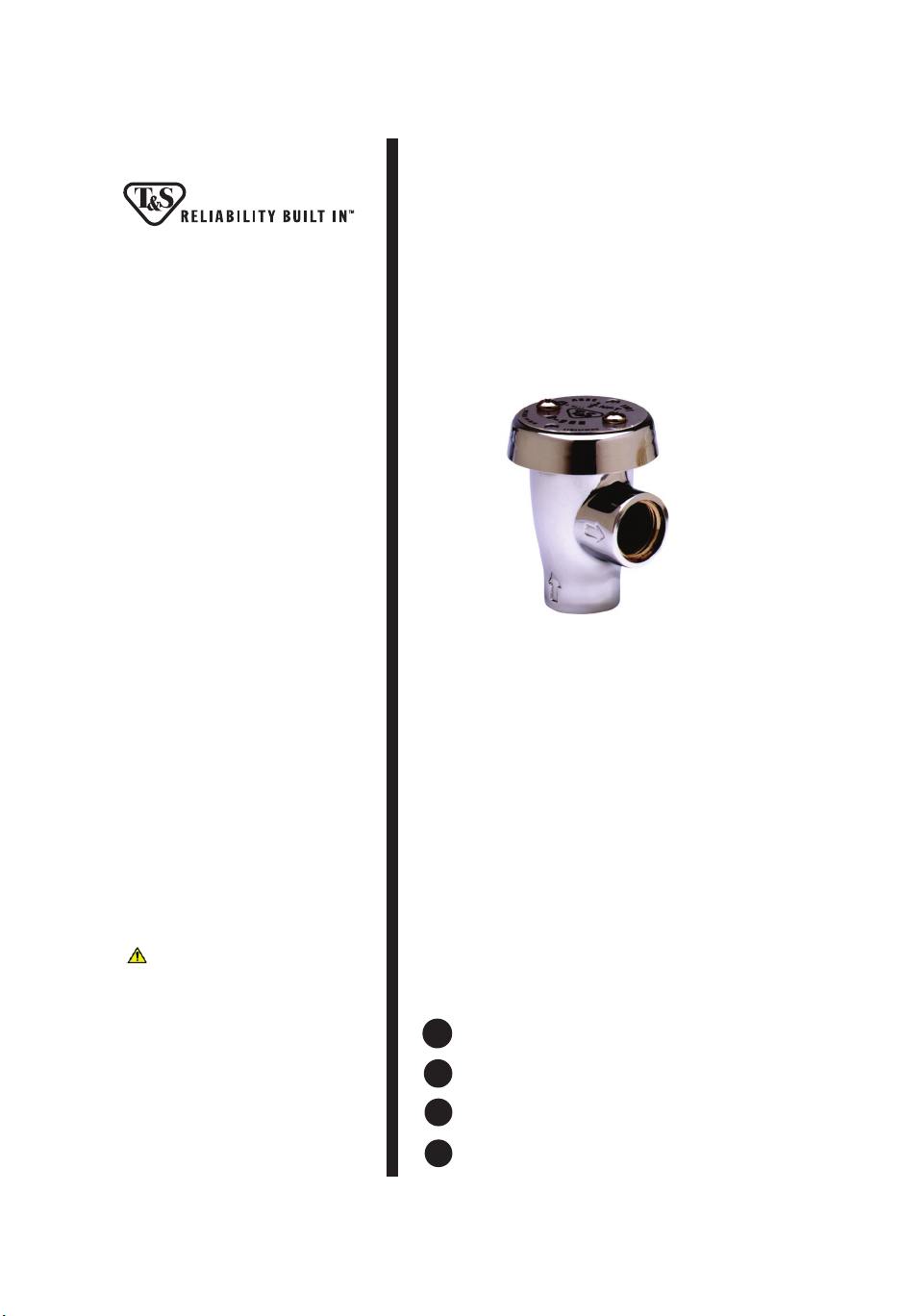
ATMOSPHERIC
VACUUM BREAKERS
B-0968 (3/8”)
B-0969 (1/2”)
Attention California Residents:
WARNING This product can expose you to
chemicals including Lead, Chromium (hexavalent
compounds) and Phthalates (DEHP) which are
known to the State of California to cause cancer
and birth defects or other reproductive harm.
For more information go to
www.P65Warnings.ca.gov.
P/N: 098-009549-45 Rev.8
Date: 10-09-19
Drawn: TED
Checked: GEF 10-31-19
Approved: JHB 10-31-09
Español:
ES
Instrucciones de instalación y mantenimiento
Français:
FR
Instructions pour l’installation et la maintenance
Deutsch:
DE
Installations- und Wartungsanleitungen
中文:
CN
安装与维护说明
Page 2
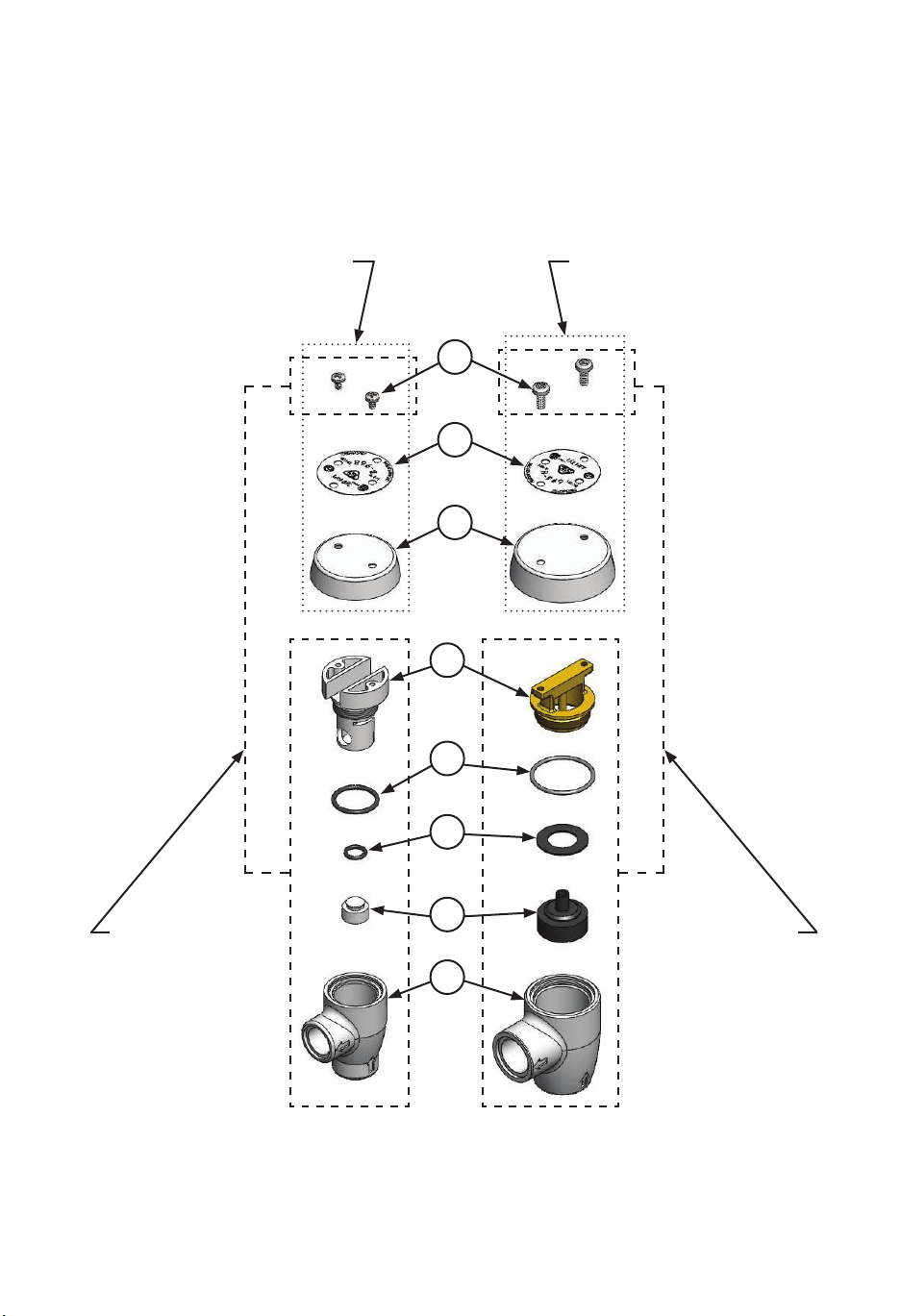
Exploded View
B-0968-HA
3/8” Vacuum Breaker
Coverplate Replacement Kit
B-0969-HA
1/2” Vacuum Breaker
Coverplate Replacement Kit
6
7
8
5
4
B-0968-RK01
3/8” Vacuum Breaker
Repair Kit
3
2
B-0969-RK01
1/2” Vacuum Breaker
1
2
Repair Kit
Page 3

Part Number Guide
B-0968 3/8” Vacuum Breaker Assembly & Kits
1 Body, Vacuum Breaker 3/8” N/A
2 Vacuum Breaker Repair Kit B-0968-RK01
2 Piston N/A
3 Small O-Ring N/A
4 Large O-Ring N/A
5 Insert N/A
6 Screws N/A
8 Vacuum Breaker Coverplate Replacement Kit B-0968-HA
6 Screws N/A
7 Nameplate N/A
8 Coverplate N/A
B-0969 1/2” Vacuum Breaker Assembly & Kits
1 Body, Vacuum Breaker 1/2” N/A
2 Vacuum Breaker Repair Kit B-0969-RK01
2 Piston N/A
3 Sealing Disk N/A
4 O-Ring N/A
5 Insert N/A
6 Screws N/A
8 Vacuum Breaker Coverplate Replacement Kit B-0969-HA
6 Screws N/A
7 Nameplate N/A
8 Coverplate N/A
3
Page 4
Important:
EN
a. The device shall be installed in accordance with the requirements of local plumbing code.
b. The device shall be installed such that it is not subject to back pressure.
Importante:
ES
a. El dispositivo se debe instalar según los requisitos del código local de instalaciones
sanitarias.
b. El dispositivo se debe instalar de tal forma que no se presente contrapresión.
Important:
FR
a. Le dispositif doit être installé conformément aux exigences du code de plomberie local.
b. Le dispositif doit être installé de manière à ne pas être soumis à une contre-pression.
Wichtig:
DE
a. Das Gerät muss entsprechend den Anforderungen der örtlichen Installationsvorschriften
montiert werden.
b. Das Gerät ist so zu installieren, dass es keinem Gegendruck ausgesetzt ist.
重要
CN
a.
设备的安装应符合当地管道规范的要求。
b.
装置的安装不应受回压的影响。
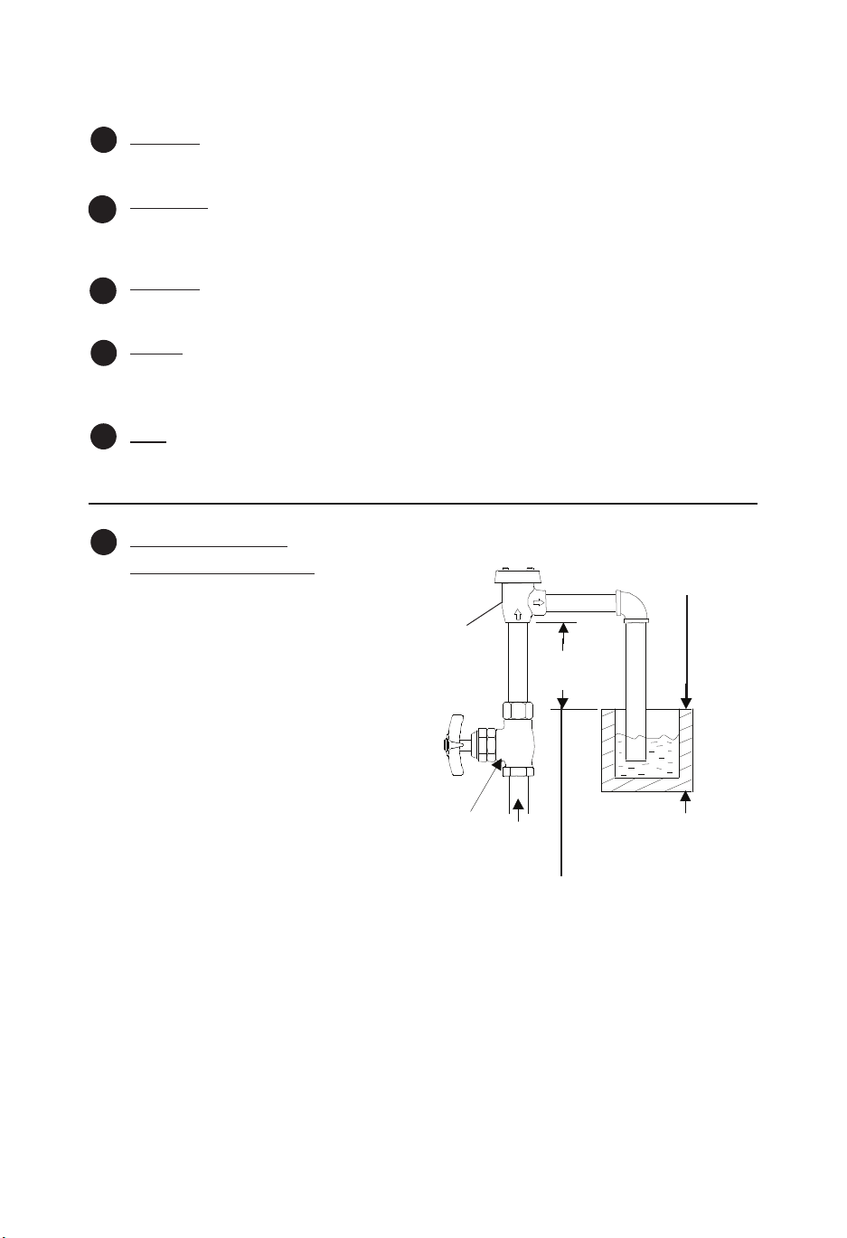
Typical Installation:
EN
Single Vacuum Breaker
Le Trop-plein ou le bord-inondation
Über uß- oder Höchwasserrand
1. Vacuum breaker must be installed with
the supply connected to the bottom and
the outlet connected to the appliance, as
1
shown below:
2. The bottom of the no.1 should be at least
6” above the ood rim of the xture or
appliance.
3. When using a portable appliance, no.1
should be installed at least 6” above the
highest point to which the outlet can be
raised, as shown.
Note: Where the device is a separate unit,
in the absence of a Critical Installation
Level (CIL) mark, the extreme bottom of the
no.1 casting should be used to determine
its installed position. Where the device is
incorporated in an outlet tube furnished
by the manufacturer, the extreme bottom
of the internal unit should be noted on the
outside of the tube by a CIL line, for use in
determining its installed position.
supply valve
Válvula Surtidora
Le Soupape de la Réserve
Zu ußventil
供水阀门
not less than 6” (CIL)
No menos de 15.24cm(CIL)
Pas moins que 15.24cm(CIL)
Nicht weniger als 15,24 cm (CIL) oberhalb der
kritischen Einbauebene
不小于6” (CIL)
xture or appliance
Accesorio ó aplicación
L’appareil
Vorrichtung oder Gerät
设备或装置
4. The water supply valve must be installed on the supply side (ahead) of the vacuum breaker,
and no shut-o valve should be installed on the outlet side (downstream).
5. The vacuum breaker should not be subjected to continuous pressure for more than twelve (12)
hours.
Note: This device should not be installed in a concealed or inaccessible location, nor where the
venting water from the device during its normal functioning may be deemed objectionable.
over ow or ood rim
Derrame ó caño de reboso
溢流或溢流边
4
Page 5
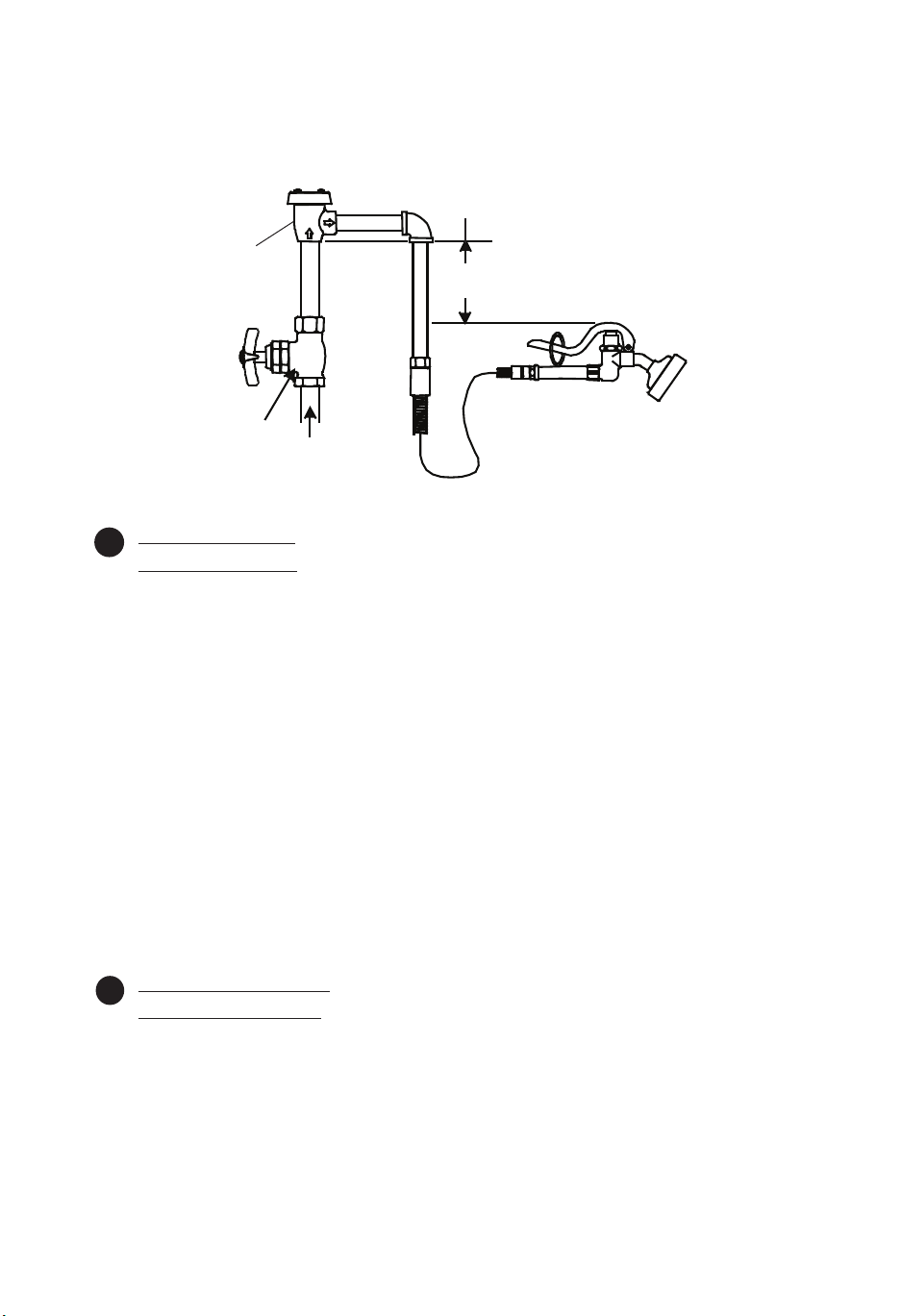
highest position of appliance not less than 6” (CIL)
Posición máxima de aplicación no menos de 15.24cm (CIL)
La position la plus haute de l’appareil pas moins 15.24 cm (CIL)
Höchster Punkt des Geräts mindestens 15,24 cm (CIL) oberhalb
der kritischen Einbauebene
到装置最高位置不低于6” (CIL)
1
supply valve
Válvula surtidora
Le Soupape de la Réserve
Zu ußventil
供水阀门
Instalación Típica:
ES
Anti-sifón singular
1. La válvula anti-sifón tiene que ser instalada, con la fuente surtidora en la parte posterior y la
salida conectada a la aplicación, como se muestra abajo:
2. El lado posterior de la parte No.1 debe ser por lo mínimo 15.24cm sobre el caño de reboso del
accesorio ó aplicación.
3. Cuando esta utilizando una aplicación portable, No.1 debe ser instalada por lo mínimo
15.24cm sobre el punto más alto en que se pueda levantar la salida, como esta demostrado.
Nota: Donde el aparato sea una unidad separada, en la ausencia de la marca (CIL) que
signi ca nivel crítico de instalación, el lado extremo posterior de la parte No.1 debe ser
utilizado para determinar la posición de instalación. Donde el aparato sea incorporado en
un tubo de salida surtido por la factoría, el lado extremo posterior de la unidad interna debe
ser señalada en la parte de afuera del tubo por una línea de CIL, para uso en determinar su
posición de instalación.
4. La válvula de surtido tiene que estar instalada en el lado del surtido (adelante) de la válvula
anti-sifón y ninguna válvula de detención debe ser instalada en el lado de salida (abajo de la
corriente).
5. La válvula anti-sifón no debe ser sometida a presión continua por más de doce (12) horas.
Nota: Este aparato no debe ser instalado en un sitio escondido o inaccesible, tampoco donde la
salida de agua del aparato durante su función normal sea juzgado perjudicial.
L’Installation Typique:
FR
La Vanne-Caisse-Vide
1. La vanne-caisse-vide devoir être installer avec l’alimentation brancher au fond et la sortie
brancher à l’appareil comme indiqué au-dessous.
2. Le fond de N°. 1 devoir être au moins 15.24 cm au-dessus le bord-inondation de l’appareil.
3. Quand on utiliser un appareil portatif, N°. 1 devoir être installer au moins 15.24 cm au-dessus le
point le plus haut qu’on pouvoir lever la sortie, comme indiqué.
5
Page 6

Noter: Si le dispositif être un élément séparé, avec l’absence d’une ligne du Niveau de L’Installation
Critique (CIL), le fond extrême de la coulée de N°.1 devoir être utiliser pour déterminer sa position
installée. Si le dispositif être incorporer dans un tube de sortie fourni par le fabricant, le fond
extrême de l’élément interne devoir être noter a l’extérieur du tube par une ligne CIL, pour
déterminer sa position installée.
4. Le soupape de la réserve de l’eau devoir être installer au côté d’alimentation (juste devant de)
la vanne-caisse-vide, et aucun soupape de sureté devoir être installer au côté de la sortie (en
aval).
5. La vanne-caisse-vide ne devoir pas être soumis à la pression continue plus de douze (12)
heures.
Noter: Le dispositif ne devoir pas être installer ni dans un emplacement caché ou inaccessible, ni
où le déchargement de l’eau du dispositif pendant la fonction normale aller être désagréable.
Normale Installation:
DE
Einfacher Vakuumschalter
1. Bei der Installation des Vakuumschalters muß die Zuführung wie gezeigt mit dem unteren
Ende, und das Aus ußrohr wie gezeigt mit dem Gerät verbunden werden.
2. Das untere Ende von Nr.1 sollte mindestens 15,24 cm über dem Über ußrand der Vorrichtung
oder des Geräts liegen.
3. Wenn ein tragbares Gerät verwendet wird, sollte Nr.1 wie gezeigt mindestens 15,24 cm über
dem höchsten Punkt, auf den das Aus ußrohr angehoben werden kann, installiert werden.
Anmerkung: Falls das Gerät eine separate Einheit ist, ist, falls eine kritische Einbauebene fehlt
(CIL), nach der Installation der äußerste untere Rand des Gußstückens Nr.1 zur Festlegung seiner
Lage zu verwenden. Falls das Gerät Teil eines Aus ußrohrs, das vom Hersteller geliefert wird, ist,
ist der äußerste untere Teil der internen Einheit auf der Außenseite des Rohrs durch eine Linie für
die kritische Einbauebene zur Bestimmung seiner Lage nach der Installation anzugeben.
4. Das Wasserzulaufventil muß an der Zulaufseite vor dem Vakuumschalter installiert werden und
auf der Aus ußseite (abwärts) sollte kein Absperrventil installiert werden.
5. Der Vakuumschalter darf keinem Dauerdruck von mehr als zwölf (12) Stunden ausgesetzt
werden.
Anmerkung: Dieses Gerät darf nicht an einer versteckten oder unzugänglichen Stelle oder an einer
Stelle, wo das Ablaufen von Wasser aus dem Gerät während des normalen Betriebs beanstandet
werden könnte, installiert werden.
典型安装:
CN
单个真空断流器
1. 安装真空断流器时,底部需连接供水,出水口需连接设备,如下所示.
2. 1号底部必须高于设备或装置的溢流边至少6”。
3. 使用轻便装置时,1号应安装在出水装置能举到的最高位置的上方至少6”的位置,如图所
示:
注意:如果设备是一个单独的装置,在没有临界安装标准(CIL)标识的情况下,应参照1号铸
件的最底端来决定安装位置。如果设备安装在制造商提供的出水管道内,则需在水管外部用
CIL线标出此内部设备的最底端,以此确定其安装位置。
4. 供水阀门必须安装在真空断流器的供水侧(前方),出水侧(下游)不能安装关水阀。
5. 真空断流器不能承受超过12小时的连续压力。
注意:本设备不能安装在隐蔽或接触不到的位置,也不应安装在装置正常使用期间排出的水
水质不合格的地方。
6
Page 7
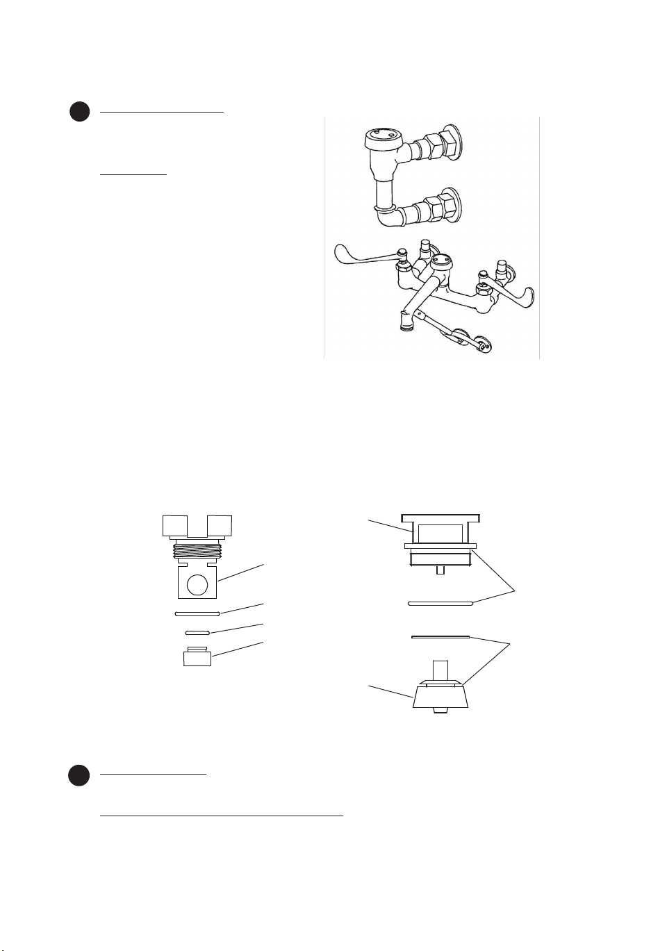
Typical Installation:
EN
Follow the instructions in the Single Vacuum
Breaker section, step 1 thru step 5.
Repair Kit:
1. For replacement parts, reorder complete
unit, or replace internal parts with a
Vacuum Breaker repair kit.
2. (See exploded view on sheet 2) Remove
the two no.6 from top of no.7, and lift o
no.7 and no.8.
3. Unscrew and remove no.5, no.4, no.3 and
no.2 from inside no.1.
4. Replace parts with new parts from kit.
5. Reassemble in reverse order.
Note: Make sure surface inside the body is
clean, and then tighten no.5 until it is rmly
seated against the inside shoulder of no.1.
B-0657
Service Sink Faucet
B-0657 Canilla de sentina
B-0657 Le Robinet De L’Évier Service
B-0657 Ausgußhahnvorrichtung
B-0657拖把池龙头
B-0929
Atmospheric Vacuum
Breaker Assembly
B-0929 Ensamblado
De Válvula Anti-sifón
Atmosférica
B-0929 la Vanne-CaisseVide Atmosphérique
B-0929 Atmosphariche
Vakuumechalicrvorrichtung
B-0929大气型真空断流
器组件
B-0968-RK01 (Kit) 3/8” Vacuum Breaker
B-0968-RK01 0,96 cm (Instandsetzungssatz)
B-0968-RK01 (维修包) 3/8”真空断流器
Instalción Típica:
ES
B-0968-RK01 3/8”
B-0968-RK01 (Trousse) 0,96 cm
5
4
3
2
B-0969-RK01 (Kit) 1/2” Vacuum Breaker
B-0969-RK01 1/2”
B-0969-RK01 1/2”
B-0969-RK01 1/2”
B-0969-RK01 (维修包) 1/2”真空断流器
5
2
Siga las instrucciones en la sección de anti-sifón singular, los pasos del 1 al 5.
Instrucciones Para Estuches De Reparo:
1. Para repuesto, ordene una unidad completa ó reemplaze partes internas con un estuche de
reparos anti-sifón.
install here
instalar aquí
installer ici
hier installieren
安装于此
4
3
install here
instalar aquí
installer ici
hier installieren
安装于此
7
Page 8

2. (Mire el dibujo ampli cado). Remueva las dos partes, No.6 de la parte de encima de la parte
No.7, y alze las partes No.7 y No.8.
3. Destornille y remueva las partes No.5, No.4, No.3 y No.2 del interior de la parte No.1.
4. Reemplaze con partes nuevas del estuche de reparo.
5. Arme de nuevo en orden reversa.
Nota: Asegúrese que la super cie dentro del cuerpo esté limpia y aprete la parte No.5 hasta que
aciente rmemente contra el sostén interno de la parte No.1.
L’Installation Typique:
FR
Suivre les instructions dans la section de la vanne-caisse-vide, de l’étape 1 jusqu’ à l’étape 5.
La Trousse À Outils:
1. Pour des pièces de remplacement, commander à nouveau l’unité complète ou remplacez les
pièces internes par le kit de réparation de briseur de vide.
2. (Voir la vue-explosé indiqué au-dessous.) Enlever les deux N°.6 du haut de N°.7, et lever N°.7 et
N°.8.
3. Dévisser et enlever N°.5 N°.4, N°.3 et N°.2 de l’ intérieur de N°.1.
4. Remplacer les parties avec les parties nouvelles de la trousse.
5. Réassembler a l’inverse.
Noter: Soyez certain que la super cie de l’ intérieur être propre, et puis resserrer N°.5 jusqu’ il est
fermement contre l’épaule de l’ intérieur de N°.1.
Normale Installation:
DE
Die Anleitungen fur den einfachen Vakuumschalter, Schritt 1 bis 5, befolgen.
Instandsetzungssatz:
1. Wenn Ersatzteile benötigt werden mu die ganze Einheit nachbestellt werden. Alternative kann
auch ein Vakuumschalter Ersatzset bestellt werden um interne Teile zu ersetzen.
2. (Siehe Darstellung in auseinandergezogener Anordnung oben.) Die beiden Teile Nr.6 von der
Oberseite von Nr.7 entfernen und Nr.7 und 8 abheben.
3. Nr.5, 4, 3 und 2 von der Innenseite von Nr.1 losschrauben und entfernen.
4. Teile durch neue Teile des Instandsetzungssatzes ersetzen.
5. In umgekehrter Anordnung wieder zusammensetzen.
Anmerkung: Sicherstellen, daß die Ober äche innerhalb des Gehäuses sauber ist, und dann Nr.5
festdrehen, bis der Teil fest gegen die innere Schulter von Nr.1 ansitzt.
典型安装:
CN
按照单个真空断流器部分的说明操作,从步骤1到步骤5。
维修包:
1. 对于替换零件,重新订购完整的装置,或使用真空断流器维修包来替换内部零件。
2. (详见第2页爆炸图)从7号顶端将2个6号拆除,并摘下7号和8号。
3. 从1号内部拧下5号、4号、3号和2号。
4. 用维修包的新零件更换零件。
5. 反序重新装回。
注意:请确保本体内部的表面清洁,然后将5号对准拧紧在1号上。
8
Page 9
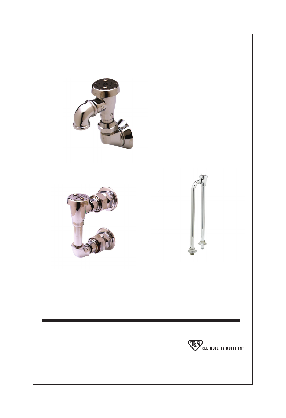
RELATED T&S BRASS PRODUCT LINE
B-0965
Atmospheric Vacuum
Breaker Assembly with
Exposed Outlet
B-0929
Atmospheric Back
Flow Preventer
B-0456
Atmospheric
Vacuum Breaker
Assembly
T&S BRASS AND BRONZE WORKS, INC.
A fi rm commitment to application-engineered plumbing products
2 Saddleback Cove, P.O. Box 1088, T & S Brass-Europe
Travelers Rest, SC 29690 ‘De Veenhoeve’
Phone: (864) 834-4102 Oude Nieuwveenseweg 84
Fax: (864) 834-3518 2441 CW Nieuwveen
E-mail:
[email protected] The Netherlands
 Loading...