


OPERATION MANUAL
TWE-250
CAPACITOR DISCHARGE
WELDER
TRU WELD EQUIPMENT COMPANY
6400 N. HONEYTOWN ROAD SMITHVILLE, OHIO 44677 (330) 725 7744 TWE@tfpcorp.com
Version 1.0
Date 8/13/2013
TRU WELD EQUIPMENT LIMITED WARRANTY
All goods produced by Truweld Equipment shall be warranted against defects including workmanship and components. No other war ranties whether expressed, verbal, or implied will apply. Warranties only apply to the original equipment purchaser.
Warranty claims will be limited to either repair or replacement of the defective materials by Truweld Equipment. At the option of Tru weld Equipment the location of where the warranty evaluation and repairs are made will be determined. All warranty claim items re turned to Truweld Equipment will be at the customer’s expense. At the option of Truweld Equipment the defect will either be repaired or replaced. Notice must be provided to Truweld Equipment of a warranty defect within 30 days that the defect or failure is incurred. Warranties are not transferable.
This warranty does not apply for equipment which is used improperly in any fashion including but not exclusive to the following:
Equipment which has been modified
Equipment which has not been installed properly
Equipment which has been used for purposes other than which it had been designed
Equipment which has not been properly maintained
Equipment which was continued to be used after a defect had been found
Equipment which was damaged in any way
Truweld Equipment will never be liable for consequential damages, loss, or expense occurring directly or indirectly from the use of the equipment covered in this warranty.
All cables, cable sets and connectors are not warranted.
Two (2) year warranty period from date of purchase
SC3402 Power Supply |
SC3400 Power Supply |
SC2420 Power Supply |
SC2402 Power Supply |
SC2400 Power Supply |
SC1900 Power Supply |
SC1950 Power Supply |
SC1600 Power Supply |
SC1650 Power Supply |
SC1400 Power Supply |
SC1450 Power Supply |
SC900 Power Supply |
TWE250 Power Supply |
|
TWE321 Power Supply |
|
TWE375 Power Supply |
|
One (1) year warranty period from date of purchase
TWESPC Power Supplies
TWP 2 Power Supply
Ninety Day warranty period from date of purchase
(Excluding cables and connectors)
TWE70000 HD Arc stud gun
TWE18500 MD Arc stud gun
TWE19000 LD Arc stud gun
TWEG CD stud gun
TWEHDG Heavy Duty CD stud gun
2

CONTENTS
Section |
Description |
Pages |
1 |
Warranty |
2 |
2 |
Table of Contents |
3 |
3 |
Product Specs and Features |
4 |
4 |
Introduction |
5 |
5 |
External Features |
6 7 |
6 |
Safety |
8 10 |
7 |
Setup And Welding |
11 17 |
8 |
Testing Weld Settings |
18 19 |
9 |
Internal Components |
20 22 |
10 |
CD Stud Gun Exploded View |
23 |
3

Product Features
Model: TWE 250
Stud Welder Description
Incorporates the latest solid state technology into a compact and rugged CD Stud Welder. This sys tem has the capacity to weld studs and pins (including cupped head pins) ranging from 14 gauge through 1/4” full flanged stainless steel studs.
SPECS |
TWE 250 |
Operational and Safety Features |
|
|
|
SIZE |
16” Length, 8 1/2” Width, 9” Height |
|
|
|
|
|
|
WEIGHT |
28 lbs. |
|
|
|
|
|
|
WELD RANGE |
14 gauge through 1/4” Stainless |
|
|
|
|
|
|
DUTY CYCLE |
30 studs per minute (including 1/4”) |
|
|
|
|
|
|
PRIMARY POWER |
110 VAC @ 50/60Hz 10 Amp circuit or 220 VAC @50/60Hz 5 |
|
|
Amp circuit |
||
|
|
||
|
|
|
|
|
CHARGE VOLTAGE |
35 200 VDC |
|
|
|
|
|
•LED Voltage Meter
•Safety Shutdown
•Cooling Fan
•Front Panel Informational LED’s
•Dial Down weld voltage control
•Digital DC voltage readout on all models (allows for more accurate and repeatable weld settings).
•Cooling fan in all models for increased efficiency.
•Dial down DC voltage setting (no need to turn off the unit when resetting to a lower voltage).
•Only 10 amp circuit requirement (unit fused @ 10 amps).
•99,000 micro farad capacitors charging to 200 VDC for greater power output @ lower DC voltage requirements.
•Terminal connections on the capacitors are over 5/8” in diameter for a good seat of the terminal buss bars to increase reliability.
•The terminal connections on the capacitors have 1/4 28 socket set screws inserted into each one. The socket set screw is used to make the connection to the buss bar. This eliminates damaging the threads in the aluminum connectors of the capacitor, ensuring a solid connection.
•Rigid internal construction connecting the entire internal unit to the front and rear panels minimizes the opportunity of the com ponents coming loose during handling or operations.
•Sheet metal is powder coated for greater durability, texture, and appearance.
•Stud Guns are ergonomically designed for better hand fit and comfort (reduces operator fatigue for increased weld repeatability).
•Stud Guns have a permanent internal spring with easy adjustment for various spring pressures allowing an increased opportunity to apply the correct spring pressure to the weld (no need for a variety of different springs for various applications).
•Stud Guns can be configured for “B” Collets, “CI” Collets, Euro Collets or standard tapered chucks.
4

INTRODUCTION
The complete range of the capacitor discharge equipment is compact, portable stud welding equipment. The units are specifically designed to enable a small diameter range of ferrous and nonferrous weld studs to be welded to light gauge metal materi als with little or no reverse side marking.
The equipment consists of a control unit, a welding hand gun, and all necessary inter connecting cables.
THE PROCESS
Capacitor Discharge (CD) stud welding is a form of welding in which the energy re quired for the welding process is derived from a bank of charged capacitors. This stored energy is discharged at the base of the specially designed CD stud and it fuses the stud to the base material. The time of the weld is determined in such a short du ration that no burn through marking is made on the finish side of the material.
CONTACT
In contact CD welding, the stud is placed under spring pressure on the material to be welded. When the capacitors are discharged, the special tip of the CD stud melts and the spring pressure forces the stud to fuse with the base material.
5

EXTERNAL FEATURES
FRONT PANEL
1
2
3
4 |
5 |
6 |
1.Weld Voltage Selector rotate to change to required voltage.
2.Welding Voltage Digital Display displays selected voltage.
3.LED Lights Charging (capacitors are being charging to desired voltage), Ready (unit is ready to weld), Reset (indicates an error and unit should be turned off).
4.Welding Ground Cable Connector (+)
5.Stud Gun Control Connector
6.Welding Stud Gun Cable Connector ( )
6
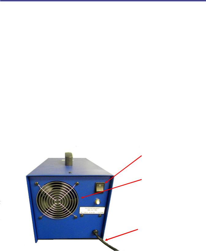
EXTERNAL FEATURES
REAR PANEL
1.On/Off Switch 2.Circuit Breaker 3.AC Power Cord
4.Manufacturer Model Number and Serial Number Plate
WARNING!
This unit operates from a 110 VAC 60 Hertz @10 amp circuit or 220 VAC 50 Hertz @ 5 amp circuit.
Do not obstruct the ventilation fan, as this may cause unit to over heat.
Do not remove any portion of the unit housing without first disconnecting the unit from the power supply.
ON/OFF Switch
Power Supply Fan
 15Amp Circuit Breaker
AC Cord
7

SAFETY
PROTECT YOURSELF AND OTHERS!
Read the safety notices before using welder.
ELECTRICAL
No portion of the outer cover of the welding controller should be removed by any one other than qualified personnel. Always disconnect the unit from the main power prior to removing cover.
•This equipment contains a transformer power supply system, which is energized by AC current and transforms the AC to DC current. Due to potential dangerous electrical input and output the equipment must be disconnected from all incom ing power when servicing.
•Capacitors store electrical energy. Check for residual charge before performing any maintenance.
•Do not use fluids to clean electrical components as these may penetrate the elec trical system and cause shorts.
Connection of the unit into service must be in accordance with the setup procedures as detailed in this manual. Operation of this equipment must be in accordance with all local, regional, and national safety codes.
8
 Loading...