

Page 1
Yaw Damper System
Installation Manual
83000-63 Rev C
TRUTRAK FLIGHT SYSTEMS
1500 S. Old Missouri Road
Springdale, AR 72764
Ph: 479-751-0250 Fax: 479-751-3397
www.trutrakap.com
Page 2
INSTALLATION MANUAL
For
Yaw Damper Systems
TABLE OF CONTENTS
Mechanical Installation Considerations.................................................................................1
RFI/EMI considerations.........................................................................................................1
Basic Servo Installation..........................................................................................................2
Yaw Damper Initial Setup & Checkout.................................................................................3
First Flight Yaw Damper .......................................................................................................4
Electrical Pin-Out...................................................................................................................5
Sorcerer Installation ...............................................................................................................6
DII installation........................................................................................................................7
Trouble Shooting....................................................................................................................8
Revision Date Description Page #
A 07/01/2008 Initial Release
B 06/18/2009 New mod wiring change 3, 5,6,7
C 12/07/2009 Updated Warranty information 8
Page 3

Mechanical Installation Considerations
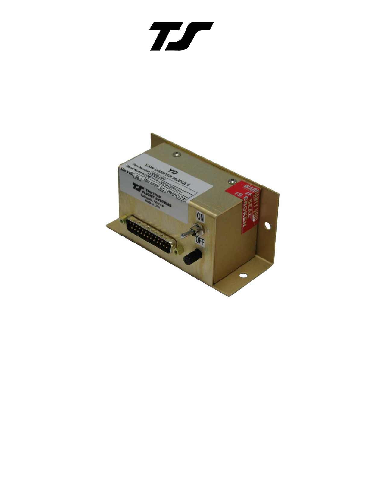
MODULE INSTALLATION
Mounting Considerations
The Yaw Damper module is designed to mount on a vertical bulkhead or horizontal surface in the
aircraft, with the bottom flange level with the aircraft, as shown on the first page. Level to the
aircraft, installation is very important as the knob on the YD module will only remove a slight
discrepancy in leveling. Install the wire connector pointing forward or aft, see installation initial
check out for details. Use aircraft installation standards for mounting and support of the YD
system.
Wiring Considerations
Use AWG #24 or larger wire for all connections unless otherwise specified. The standard solder
pin contacts supplied in the connector kit are compatible with up to AWG #18 wire. In cases
where some installations have more than one component sharing a common circuit breaker, sizing
and wire gauge is based on, length of wiring and current draw on units. In these cases, a larger
gauge wire such as AWG #20 may be needed for power connections. Do not attach any wires to
the outside of the YD or route high current wires within six (6) inch of the module. Ensure that
routing of the wiring is not exposed to sources of heat, RF or EMI interference. Check that there
is ample space for the cabling and mating connectors. Avoid sharp bends in cabling and routing
near aircraft control cables.
RFI/EMI considerations
The YD module is shielded and does not generate any appreciable level of electromagnetic
interference. Moreover, the servo lines (except for power and ground) are low-current and cannot
contribute to RF interference. The servo power and ground lines do have switching currents
through them, but so long as there are no parallel runs of servo power and ground lines with such
things as poorly-shielded antenna lines or strobe light power lines, there is no need to shield the
servo harnesses. The YD module itself has been internally protected from RF interference and
has been tested under fairly extreme conditions, such as close proximity to transmitting antennas.
However, it is always good practice to insure that such antennas are properly shielded and not
routed directly over or under sensitive panel-mounted electronic equipment. Most problems in
this area are the result of improper RF shielding on transmitting antennas, microphone cables, and
the like.
TruTrak Flight Systems Yaw Damper Installation Manual
December 2009 1 8300-063 Rev C
Page 4

Servo Installation
The installation information in this section is extremely important and must be
clearly understood by the installer. Improper servo installation or failure to observe
and diagnose installation problems prior to flight can result in extremely serious
consequences, including loss of ability to control the aircraft. If there are any
questions on the part of the installer it is mandatory to resolve these questions prior
to flight of the aircraft.
Most modern experimental aircraft use push-pull tubes to drive the primary controls. These tubes
generally have a total travel of 3” or less; therefore, it is best to connect the autopilot servo to the
primary control by the same method. This connection consists of an arm on the servo connected
by a push-pull rod to the primary control. Rod-end bearings are required on each end of the pushpull rod. The servo arm must not rotate even near to the point called OVER CENTER, the point
at which the primary aircraft control would lock up. Some aircrafts mechanical primary control
installations will not allow this to occur and do not need the servo stops. This is a condition that
would result from the servo being back driven when the pilot operates the controls, or from the
servo itself driving the controls to a stop. To protect against this mechanical stops are supplied
with the servos. These stops are drilled so that they can be mounted at different angles as
required (18° intervals).
In addition to the proper use of the stop it is important to know the amount of travel on the
primary control that the servo can handle. With the push rod connected to the outermost hole (1
½”) the travel on the primary cannot exceed 2 ½”, the intermediate hole 2 1/16”, and the inner
hole 1 5/8”.
It is important to note that at the neutral point of the control the SERVO ARM must be
PERPENDICULAR to the push rod, and that the stop must be mounted so as to limit travel as
near as possible to equal amounts in both directions. In certain factory-designed installations
there may be well-proven exceptions.
There will be installations in which space does not permit the use of the stop. When this is done
the aircraft’s primary control stops must be positive and care must be taken to be sure that at the
neutral point the servo arm is perpendicular to the push rod, and that the travel limits of the servo
arm are not exceeded.
There are installations in which the travel of the push-pull tube exceeds the allowable 2 ½”. For
such installations, the drive can be applied to a bell crank at a radius point that moves the desired
2 ½” of maximum allowed travel in the outermost hole of the arm.
When there is no way to have a drive point of less than 2 ½” or when the primary control is cabledriven it is necessary to use the capstan-cable servo drive. When this is done the servo should be
mounted so that the 1/16” diameter cable which wraps around the capstan when extended parallel
to the primary cable is approximately 3/16” from the primary cable. If the primary control travel
does not exceed 5” the cable locking pin will be 180° away from the point at which the cable
leaves the capstan. When the primary control is at the neutral point this means the total cable
wrap around the capstan is 360°. If the primary control travel is greater than 5” the cable wrap is
720°and the pin is adjacent to the output point when the primary control is at the neutral point.
The cable clamps when properly installed will not slip and thus get loose, but it is desirable to
NICO press or swedge a fitting on to the cable so as to provide added assurance that the cable will
TruTrak Flight Systems Yaw Damper Installation Manual
December 2009 2 8300-063 Rev C
Page 5

not become slack. If the bridle cable is not sufficiently tight there will be lost motion in the
autopilot drive. This will result in hunting (oscillation).
Yaw Damper Initial Setup & Checkout
The next step in the installation procedure is to verify electrical operation of the yaw damper.
Before this test, remove the yaw damper module from its mounting location so that it can be
manually tilted. Verify the direction strap is correctly wired on pins 17 and 18 of J501, the 25-pin
yaw damper connector. If the unit is to be mounted on the rear side of a bulkhead, connector
pointing aft, the strap between pins 17 and 18 of J501 must be absent. If the unit is to be
mounted on the front side, connector pointing forward, the jumper must be present. Enter the Yaw
Damper setup mode in the autopilot controller, advance to and set YD ACTIVITY value to 15.
Advance to the MIN AIRSPD field, set the minimum airspeed to 0. MIN airspeed must be set to
0 on the ground to engage the YAW damper.
Having verified the strap, manually center the rudder and then engage the yaw damper by
following the correct procedure (see autopilot installation manual) for the autopilot programmer.
Position the toggle switch on the YD module in the GYRO “OFF” position to set the centering,
hold the yaw damper module in the same position it will occupy when mounted on the bulkhead
in an approximately level position that stops the servo rotation. Tilt the module to simulate the
aircraft banking to the right. The yaw damper should respond by commanding the rudder to move
towards the right, and conversely a bank to the left should move the rudder towards the left. If the
servo moves in the wrong direction during this test, double-check the correct jumper setting on
pins 17 and 18 and if found to be correct, interchange the wires on the yaw damper servo
connector (pins 4 and 5 of J401) or at the connector on the yaw damper module (pins 12 and 13 of
J501). Re-check the direction after exchanging the wires.
Having verified the correct direction of response to the tilt sensor, secure the yaw damper module
to the bulkhead. Re-engage the yaw damper and adjust the leveling potentiometer, the black knob
which protrudes from the face of the yaw damper module, to stop the movement of the servo
(rudder). The aircraft should be on a level surface (with its “ball” centered) for this adjustment.
Once the proper tilt adjustment is done, switch the toggle switch toward “gyro on” and push on
the tail to confirm correct servo movement. Rudder must move in direction of empennage
direction. Example: Empennage moves away from you, rudder swings way from you.
Once the proper adjustment is done and confirmed, disengage the yaw damper, re-enter the Yaw
Damper setup mode, advance to and set YD ACTIVITY value to zero. This insures that the yaw
damper adjustments do not complicate the first test flight of the autopilot. Advance to the MIN
AIRSPD field, set the minimum airspeed to the desired value for actual flight. This should be an
indicated airspeed (in knots) which is safely above the stall but below normal approach or climb
out speeds. Make sure that the toggle switch on the Yaw Damper controller is toggled toward
GYRO “ON” for flight.
The remaining adjustments relate to the dynamics of flight.
TruTrak Flight Systems Yaw Damper Installation Manual
December 2009 3 8300-063 Rev C
Page 6

First Flight Yaw Damper
The Yaw Damper system requires adjustment of the Yaw Damper parameters. With the
autopilot disengaged, level the aircraft and hand-fly the aircraft in still air. With your feet off the
rudder pedals, confirm that the ball is centered. If the ball is NOT centered, correct the aircraft
out of trim condition before proceeding. Press the appropriate button to engage the Yaw Damper.
Then enter the YD setup screen. Cycle through the settings already completed, until YD
LEVELING is shown on the display. Centering is adjustable from -8 to 8 and has enough
authority to move the ball approximately one and one half times the width of the ball in either
direction. (Coarse adjustment was made using the potentiometer in the yaw damper module
during the earlier Initial Checkout Procedure.) Adjust the centering so that the ball is centered. If
unable to center the ball in flight, confirm Initial check out setting. Once the YD LEVELING has
been set, advance to the next setup screen.
The YD ACTIVITY determines how aggressively the yaw damper responds to yaw disturbances.
Yaw damper activity can range from 0 (off) to 12 (extremely aggressive). For this setting, it is
best to find light to moderate turbulence so the effects can be properly observed. Having found
suitable conditions, gradually increase the value of YD ACTIVITY in order to obtain an
appropriate level of response to yaw disturbances. Too high a value will result in rapid
oscillation, while too low a value will essentially disable the quick response of the yaw damper to
turbulence. Within the acceptable range of operation, there is still room to account for personal
preferences. So long as the yaw damper’s YD ACTIVITY value is not so high as to cause
oscillation, the response is simply set according to preference and comfort. Once the YD
ACTIVITY has been set, exit the setup mode.
With the DII Series autopilot Yaw Damper installations only. The two potentiometers that are
needed (see schematic) serve the function of the Yaw activity and the in-flight ball centering.
The normal operation of the autopilot will turn the yaw damper on any time the autopilot is
engaged, and the yaw damper will stay on after the autopilot is disengaged. During final
approach and the diminishing of the airspeed below the MIN AIRSPD setting, the yaw damper
will automatically disengage. To disengage the yaw damper prior to that point, simply use the
YD or TRK button to toggle the yaw damper off. When the autopilot is in the Off mode, the YD
or TRK button acts as a yaw damper on/off toggle function and the display will indicate YD ON
or YD OFF.
This concludes the in-flight setup of the TruTrak Yaw Damper.
TruTrak Flight Systems Yaw Damper Installation Manual
December 2009 4 8300-063 Rev C
Page 7

Electrical Pin-Out
The table below provides a brief explanation of each pin function on the 25-pin connector P501.
1
2345678910111213
14 15 16 17 18 19
20 21 22 23 24 25
25-Pin Connector P501
P101
Function Notes
Pin
1 Power. Connects to autopilot master or pitch servo power line from programmer. +12 or +28 V
2 Ground. Connect to aircraft ground. Aircraft ground
3 Yaw Damper Activity. A signal from the autopilot which sets the amount of response the
yaw damper exhibits to azimuth disturbances and “ball” deflection.
4 Yaw Damper Leveling. A signal from the autopilot which is used for fine adjustment of
the “ball” in a yaw damper.
0 to +5v at YD
For testing only
0 to +5v at YD
For testing only
5 Torque Control. Servo torque control output to servo pin 6 +5v at servo pin 6
For testing only
6 No Connection. Reserved for future expansion.
7 No Connection. Reserved for future expansion.
8 Yaw Damper Activate. A signal from the autopilot which turns on the yaw damper
function.
0 to engaged at YD
For testing only
9 No Connection. Reserved for future expansion.
10 PH1P. Servo drive line output to servo pin 3.
11 PH1N. Servo drive line output to servo pin 2.
12 PH2N. Servo drive line output to servo pin 4. Swap to reverse
13 PH2P. Servo drive line output to servo pin 5. Servo direction
14 Power. Power connection to pitch servo pin 1 Connected internally to
pin 1
15 Ground. Ground connection to pitch servo pin 9. Connected internally to
pin 2
16 No Connection. Reserved for future expansion.
17
Jumper to pin 18 for mounting with the connector forward
18
Jumper to pin 17 for mounting with the connector forward
19 No Connection. Reserved for future expansion.
20 No Connection. Reserved for future expansion.
21 No Connection. Reserved for future expansion.
22 No Connection. Reserved for future expansion.
23 No Connection. Reserved for future expansion.
24 No Connection. Reserved for future expansion.
25 No Connection. Reserved for future expansion.
TruTrak Flight Systems Yaw Damper Installation Manual
December 2009 5 8300-063 Rev C
Page 8

Sorcerer Installation
Sorcerer with rudder trim
TruTrak Flight Systems Yaw Damper Installation Manual
December 2009 6 8300-063 Rev C
Page 9

DII installation
Stand alone installation
TruTrak Flight Systems Yaw Damper Installation Manual
December 2009 7 8300-063 Rev C
Page 10

Trouble Shooting
Problem Cause Corrective Action
Yaw Servo will not
move and is quiet
Yaw servo will not
move but there is
clicking
Rudder moves in
wrong direction
Rudder does not move
when tail pushed
Unable to center ball in
flight
No aircraft voltage and /or
engage signal to Yaw
module
No aircraft voltage and /or
torque signal to Yaw servo
Module strap or servo wires
incorrect
Gyro switch not in correct
position
Ground centering procedure
incorrect
Correct power, ground, and / or
Engage wiring
Correct power & ground.
Check @5 voltage at pin 6 at
servo Yaw engaged
Correct wire strap or servo
wires per installation
instructions
Confirm gyro switch in “ON”
position
Perform centering procedure
per
Initial Setup instructions
Warranty On TruTrak Flight Systems Products
We here at TruTrak Flight Systems know how important it is to feel as though the customer is purchasing a
product that the manufacturer is going to stand behind. For this reason we want offer more than the basic
one year warranty that is standard to this industry. The warranty on all TruTrak products will be three
years from the date of purchase. Abuse and misuse of a product are not covered under this warranty.
Modification to a product may void the warranty, as well as carry a penalty when upgrading to another
product. This three year warranty will be for all products except the Pictorial Turn & Bank, which will
continue to have a warranty of one year from the date of purchase.
TruTrak Flight Systems No Penalty Upgrade Policy
As the product line continues to grow, it becomes increasingly difficult to maintain a simple upgrade
policy. We do want to reward our repeat customers by allowing a lower cost upgrade from one system to
another; however we are not able to offer this across the board on all products. If you are considering an
upgrade, please call and we will give you a quote on what this would cost. Many products that we sell
today are upgradeable for only the difference in system price. Because we continually strive to have the
most up to date products possible, we occasionally have to discontinue products. We will continue to offer
discounted upgrades even for our discontinued products.
TruTrak Flight Systems Yaw Damper Installation Manual
December 2009 8 8300-063 Rev C
Page 11

RETURN MERCHANDISE POLICY AND PROCEDURE
• Under no circumstances should products be returned to TruTrak without first obtaining a Return of
Merchandise Authorization number (RMA #) from TruTrak. An RMA# may be obtained by
INTERNATIONAL SHIPMENTS:
contacting us at 866-878-8725.
• Products that do not have an RMA # will not be processed.
• Please include documentation stating the reason for the return and describing any symptoms,
failure modes, suspected causes of damage, diagnostics performed, data collected, etc.
• Product(s) should be packaged in their original shipping containers. In lieu of this, they should be
very carefully packaged in containers suitable to protect them during transit. Note that damage
caused during shipping will not be repaired under warranty.
• The outside of the box must be clearly marked with the RMA # issued by TruTrak and the RMA #
must also be noted on the return documents.
• Products will be returned to the customer at no charge via FedEx Ground or UPS Ground. If
customer requests expedited shipping (2
nd
Day or Overnight) they will be charged the shipping
cost and must supply a credit card number.
• Trutrak sends all International shipments with an insurance value on all products. Trutrak pays for
shipping only. The customer is responsible for any and all additional fees, duties, taxes associated
with the shipment.
• When sending products to Trutrak for repair or otherwise please be advised that the customer is
responsible for all charges and fees associated with shipment. For your protection, items should
be insured for the full value.
•
Trutrak states on all product returns “WARRANTY REPAIR AT NO CHARGE TO CUSTOMER. A
COMMERCIAL INVOICE VALUE OF $___ GIVEN FOR INSURANC E PURPOS ES ONLY”
Please keep in mind that your government or another entity in your country may impose a charge for custom
and/or brokerage fees, duties and taxes on items received from the US. These charges do not originate from our
company nor do we benefit from them in any way. You are responsible for payment o f all custom and brokerage
fees, duties and taxes that may be imposed when these goods are imported into your country.
• Send ALL return shipments to:
Trutrak Flight Systems, Inc., 1500 South Old Missouri Road, Springdale, AR 72764 USA
Attention: Returns Dept. RMA# ______________
TruTrak Flight Systems Yaw Damper Installation Manual
December 2009 9 8300-063 Rev C
Page 12

TruTrak Flight Systems, Inc.
1500 S. Old Missouri Rd.
Springdale AR 72764
(479) 751-0250
FAX (479) 751-3397
www.trutrakap.com
 Loading...