


ADI Pilot II
Table of contents
 Loading...
ADI Pilot I & II Series Autopilots
Installation & Users Manual
8300-012 Rev B
TRUTRAK FLIGHT SYSTEMS
1500 S. Old Missouri Road
Springdale, AR 72764
Ph: 479-751-0250 Fax: 479-751-3397
Toll free: 866-TRUTRAK
866-(878-8725)
www.trutrakap.com

INSTALLATION & USERS MANUAL
for
ADI Pilot I & II Series Autopilots
TABLE OF CONTENTS
ADI Pilot I & II Power Up............................................................................................................................................1
ADI Pilot I & II Basic Operation..................................................................................................................................1
ADI Pilot I & II Nav Mode Operation.......................................................................................................................... 1
ADI Pilot II Pitch Axis Operation ................................................................................................................................2
Mechanical Considerations........................................................................................................................................... 2
Pitot / Static Connections..............................................................................................................................................3
RFI / EMI Considerations............................................................................................................................................. 3
ADI Pilot I cutout .........................................................................................................................................................4
ADI Pilot II cutout ........................................................................................................................................................5
ADI Pilot I & II Ground Checkout ...............................................................................................................................6
ADI Pilot I First Flight .................................................................................................................................................8
ADI Pilot II First Flight ................................................................................................................................................8
Gyro Back-Up Mode ..................................................................................................................................................10
Electrical Pin-Out .......................................................................................................................................................11
ADI Pilot I & II Wiring Diagram ...............................................................................................................................12
ADI Pilot I & II Block Diagram .................................................................................................................................13
GPS Setup Guide ........................................................................................................................................................14
Portable GPS’s ......................................................................................................................................................................... 14
Panel mount GPS’s .................................................................................................................................................................. 17
Definitions ..................................................................................................................................................................19
ADI Pilot I & II Settings............................................................................................................................................. 20
Revision Date Description Page #
A 07/01/2008 Initial Release
B 12/09/2009 Warranty update 25

ADI Pilot I & II Power Up
NOTE: When powering up the autopilot ensure that the aircraft is as still as possible for 10
seconds.
The power up of the autopilot takes approximately ten seconds. During the power cycle it is very important that the aircraft be
as still as possible for the initialization of the internal gyro. While the autopilot is in the power up mode, the display will show
three flashing
a valid GPS signal present the display will show three non-flashing
groundspeed (approximately 15 knots) the display will begin showing the digital DG.
(“–”) characters. If there is a GPS signal present the display will now change to read (“OFF”). If there is not
(“–”) characters. Once the aircraft achieves sufficient
ADI Pilot I & II Basic Operation
If a valid GPS signal is present, and the autopilot is not engaged the display of the autopilot is a digital DG displaying a
gyroscopically smoothened GPS track. Once the aircraft is off the ground and at a safe altitude, the autopilot can be engaged.
There are several ways to engage the autopilot. Pressing and releasing the knob will engage the autopilot and the “AP” light
will light up. If a GPS signal is present, the autopilot will display the ground track before being engaged and will now hold the
track. If there is no GPS signal the display will show
The second way to engage the autopilot is with the Control-Wheel Switch, pushing and holding the control wheel switch for
approximately 1-1/2 seconds and releasing will engage the autopilot and the “AP” light will light up.
“0” and will be in “gyro back-up” mode instead of track hold mode.
Changing the selected track can be done two different ways. One way in which the track can be changed is to rotate the knob.
Each detent will be a one-degree change in selected track. If the knob is pushed in and rotated each detent will be a 5 degree
change in selected track. If there is no GPS signal present rotating the knob will change the selected bank angle by
approximately one-degree per detent, up to 30 degrees. The other way to change the selected track is with the Control-Wheel
Switch. Pushing and holding the Control-Wheel Switch will disengage the servo and the display on the autopilot will be a
Digital DG .While holding the Control-Wheel Switch, fly the aircraft manually to the desired track using the Digital DG
display as a reference. Upon release of the Control-Wheel Switch, the servo will re-engage and the autopilot will now fly the
new selected track. If there is no GPS signal present the Digital DG will not be displayed.
Disengaging the autopilot can be done in two different ways. Pressing and holding the knob for approximately 1-1/2 seconds
will disengage the autopilot. The second way to disengage the autopilot is with the Control-Wheel Switch. Momentarily
pushing and releasing the Control-Wheel Switch will disengage the autopilot.
ADI Pilot I & II Nav Mode Operation
When there is a flight plan present in the GPS the autopilot can follow the programmed flight plan. To enter the Nav Mode,
press and release the knob and the “NAV” light will light up. (Take care not to hold the knob for more than 1-1/2 seconds or
the autopilot will disengage.) The auto pilot will intercept the NAV track at about a 45 degree angle. The autopilot display
will now once again become a Digital DG, showing the current ground track. Pressing and releasing or rotating the knob on
the autopilot will exit the Nav Mode. When on course, 1 or 2-degree excursions are normal. When the end of the flight plan is
reached or the flight plan is cancelled on the GPS unit, the autopilot will continue flying the track it was flying when the flight
plan ended. If the flight plan has multiple waypoints, the autopilot will make the necessary turn at each waypoint. Because,
typically, the information from the GPS to the autopilot does not change until the waypoint is crossed, the autopilot will
over-fly the waypoint, and then will fly back to intercept the new course line. Some GPS units have a “turn anticipation”
feature, and if this feature is enabled on the GPS the autopilot may turn prior to reaching a given waypoint.
TruTrak Flight Systems ADI Pilot I & II Autopilot Installation Manual
December 2009 1 8300-012 Rev B
ADI Pilot II Pitch Axis Operation
Once the aircraft is off the ground and at a safe altitude, the autopilot can be engaged. Pressing and releasing the lower left
knob will engage the pitch axis of the autopilot and the “ALT” light will light up. The autopilot will now hold the current
altitude. The pitch axis can be used independently of the roll axis. If there is a trim sensing servo installed and the aircraft
becomes out of trim then you will see a moving bar on the left side of the display telling the pilot which way to trim the
aircraft. The altitude hold must be engage to show out of trim. When the difference between the current altitude and the initial
selected altitude is more than approximately 50 feet you will see a moving bar on the left side of the display, showing which
way to go to correct the difference in altitude. Many times on a long flight the barometric setting on the altimeter will need to
be adjusted, the pitch axis does NOT have to be disengaged to move the aircraft to the correct altitude. Once the aircraft
altimeter is correctly set, push and hold the left knob of the autopilot. While continuing to hold the knob in, the current altitude
can be adjusted up to 90 feet in either direction.
Disengaging the pitch axis of the autopilot can be done in three different ways. Pressing and releasing the lower left knob will
disengage the pitch axis of the autopilot. If the roll axis is engaged, push and holding the lower right knob for approximately
1-1/2 seconds will disengage both the roll and pitch axis of the autopilot. Another way to disengage the autopilot is with the
Control-Wheel Switch. Momentarily pushing and releasing the Control-Wheel Switch will disengage both the roll and pitch
axis of the autopilot.
Mechanical Considerations
The installation information in this section is extremely important and must be clearly
understood by the installer. Improper servo installation or failure to observe and diagnose
installation problems prior to flight can result in extremely serious consequences, including
loss of ability to control the aircraft. If there are any questions on the part of the installer it
is mandatory to resolve these questions prior to flight of the aircraft.
Most modern experimental aircraft use push-pull tubes to drive the primary controls. These tubes generally have a total travel
of 3” or less; therefore, it is best to connect the autopilot servo to the primary control by the same method. This connection
consists of an arm on the servo connected by a push-pull rod to the primary control. Rod-end bearings are required on each
end of the push-pull rod.
The servo arm must not rotate even near to the point called OVER CENTER, the point at which the primary
aircraft control would lock up. Some aircrafts mechanical primary control installations will not allow this to
occur and do not need the servo stops.
This is a condition that would result from the servo being back driven when the pilot operates the controls, or
from the servo itself driving the controls to a stop. To protect against this, mechanical stops are supplied with the
servos. These stops are drilled so that they can be mounted at different angles as required (18° intervals).
In addition to the proper use of the stop it is important to know the amount of travel on the primary control that
the servo can handle. With the push rod connected to the outermost hole (1 ½”) the travel on the primary cannot
exceed 2 ½”, the intermediate hole 2 1/16”, and the inner hole 1 5/8”.
It is important to note that at the neutral point of the control the SERVO ARM must be PERPENDICULAR to the
push rod, and that the stop must be mounted so as to limit travel as near as possible to equal amounts in both
directions. In certain factory-designed installations there may be well-proven exceptions.
There will be installations in which space does not permit the use of the stop. When this is done the aircraft’s primary control
stops must be positive and care must be taken to be sure that at the neutral point the servo arm is perpendicular to the push rod,
and that the travel limits of the servo arm are not exceeded.
There are installations in which the travel of the push-pull tube exceeds the allowable 2 ½”. For such installations, the drive
can be applied to a bell crank at a radius point that moves the desired 2 ½” of maximum allowed travel in the outermost hole of
the arm.
When there is no way to have a drive point of less than 2 ½” or when the primary control is cable-driven, it is necessary to use
the capstan-cable servo drive. When this is done the servo should be mounted so that the 1/16” diameter cable which wraps
around the capstan when extended parallel to the primary cable is approximately 3/16” from the primary cable. If the primary
control travel does not exceed 5” the cable locking pin will be 180° away from the point at which the cable leaves the capstan.
TruTrak Flight Systems ADI Pilot I & II Autopilot Installation Manual
December 2009 2 8300-012 Rev B

When the primary control is at the neutral point this means the total cable wrap around the capstan is 360°. If the primary
control travel is greater than 5” the cable wrap is 720°and the pin is adjacent to the output point when the primary control is at
the neutral point.
The cable clamps when properly installed will not slip and thus get loose, but it is desirable to NICO press or swedge a fitting
on to the cable so as to provide added assurance that the cable will not become slack. If the bridle cable is not sufficiently tight
there will be lost motion in the autopilot drive. This will result in hunting (oscillation).
Pitot and Static Connections
All multi-servo TruTrak autopilots require connections to the pitot and static lines. The preferred method of this connection
would be tee fittings near the aircraft’s altimeter. The static line for the autopilot requires due care in its construction, as
excessive lag or insufficient static orifices can cause the autopilot to oscillate (hunt) in pitch. Although there is compensation
within the autopilot sufficient to handle moderate amounts of lag, the importance of a good static port and line cannot be
overstated. In some cases problems can be caused by having a large number of devices (including the autopilot) connected to a
single, insufficient, static port. In other cases, the static line itself is adequate but there are one or more devices connected to the
same line, one of which has a large static reservoir. A simple remedy for this problem, if it occurs, is a tee-fitting near the static
port, and a dedicated line to the autopilot only. Obviously, an insufficiently-large orifice coupled with large static reservoirs
can aggravate the problems associated with lag.
RFI/EMI considerations
The autopilot programmer is shielded and does not generate any appreciable level of electromagnetic interference. Moreover,
the servo lines (except for power and ground) are low-current and cannot contribute to RF interference. The servo power and
ground lines do have switching currents through them, but so long as there are no parallel runs of servo power and ground lines
with such things as poorly-shielded antenna lines, strobe light power lines, landing lights, navigation lights, or Pitot heat, there
is no need to shield the servo harnesses.
The autopilot itself has been internally protected from RF interference and has been tested under fairly extreme conditions,
such as close proximity to transmitting antennas. However, it is always good practice to insure that such antennas are properly
shielded and not routed directly over or under sensitive panel-mounted electronic equipment. Most problems in this area are the
result of improper RF shielding on transmitting antennas, microphone cables, and the like. The most sensitive input to the
autopilot is the Control Wheel Switch input. This line should not be routed in parallel with transmitting antennas or other
sources of known RF interference. If necessary, it can be shielded with the shield connection to pin 13 of the autopilot
connector.
TruTrak Flight Systems ADI Pilot I & II Autopilot Installation Manual
December 2009 3 8300-012 Rev B
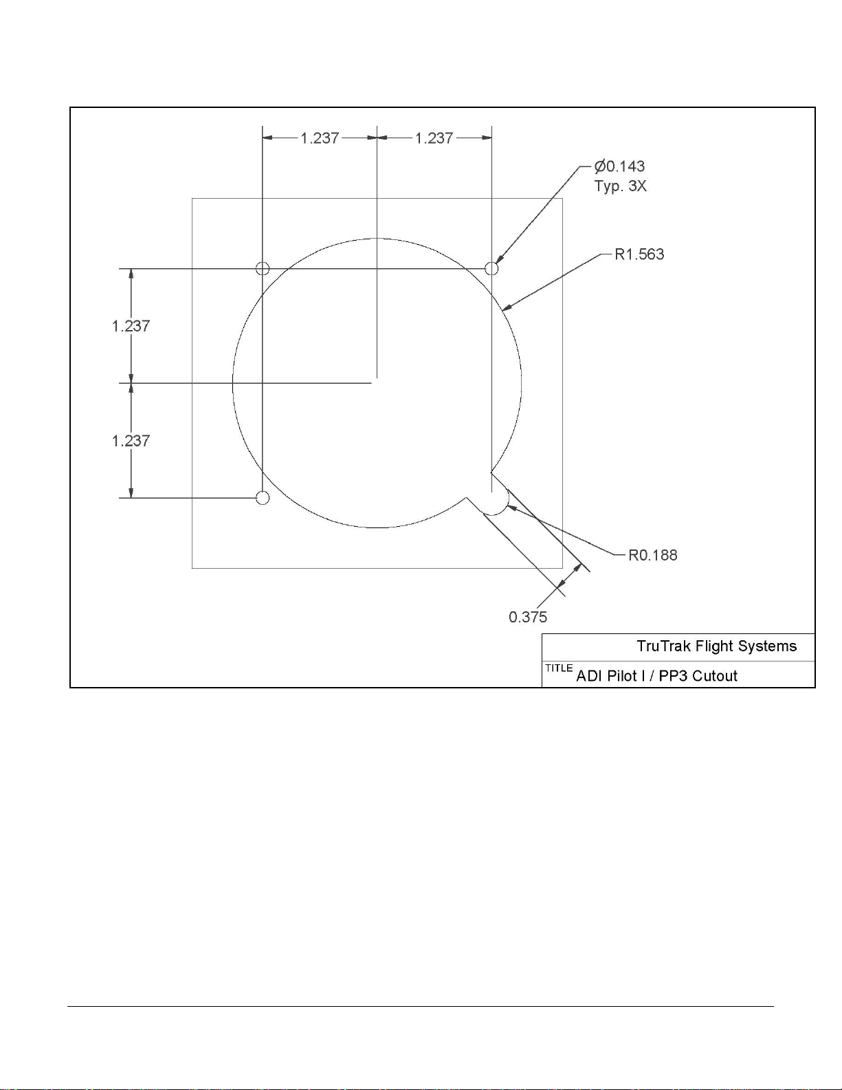
ADI PILOT I CUTOUT
TruTrak Flight Systems ADI Pilot I & II Autopilot Installation Manual
December 2009 4 8300-012 Rev B

ADI PILOT II CUTOUT
TruTrak Flight Systems ADI Pilot I & II Autopilot Installation Manual
December 2009 5 8300-012 Rev B

ADI Pilot I & II Ground Checkout
Once wiring is completed the autopilot should be tested in the aircraft while on the ground. The first step is to enter the setup
mode on the autopilot and set all parameters to their correct values. Apply power to the autopilot programmer.
When power is first applied to the unit, the display will show three flashing dash (“–”) characters. After approximately ten
seconds, the autopilot is ready to be set up for operation, indicating three non
happens to be connected to the autopilot, has a valid position fix, and is running at the correct baud rate, the autopilot will
indicate the word “OFF” instead of the three dashes.)
Engage the autopilot by pressing and releasing the lower right knob. Then press and hold the knob for approximately 5
seconds, until the first setup screen is displayed.
This display will show a flashing “1” and a two-digit number from 0 to 24, representing the lateral activity level. With the
activity setup screen on the display, rotate the lower right knob as necessary to adjust the lateral activity value to a value of 1 or
2. Press and release the lower right knob to enter the activity value and advance to the next screen.
The second setup screen, with a flashing “2” is used to set the lateral torque. Rotate the lower right knob as necessary to adjust
the torque value close to the maximum value of 12. Once that is done, press and release the lower right knob to enter that
value and advance to the next screen.
The third setup screen, with a flashing “3” is used to set the micro activity. This setting should be left at zero unless advised by
the factory. This setting is used to remove lost motion from the control system. Press and release the lower right knob to
advance to next setup screen.
The fourth setup screen, with a flashing “4” is used to set the baud rate (speed) of the serial interface to the GPS receiver.
Select either 48 or 96. Where 48 is a baud rate of 4800 and 96 is a baud rate of 9600. Having chosen the desired baud rate,
press and release the lower right knob to enter that value and advance to the next screen.
-flashing dashes on the display. (If a GPS unit
The fifth setup screen, with a flashing “5” is used to set the vertical activity ADI P II ONLY. With the activity setup screen on
the display, rotate the lower right knob as necessary to adjust the lateral activity value to a value of 1 or 2. Press and release
the lower right knob to enter the activity value and advance to the next screen.
The sixth setup screen, with a flashing “6” is used to set the vertical torque ADI P II ONLY. Rotate the lower right knob as
necessary to adjust the torque value close to the maximum value of 12. Once that is done, press and release the lower right
knob to enter that value and advance to the next screen.
The seventh setup screen, with a flashing “7” is used to set the minimum airspeed. A setting of “- -“ shows up when the lower
right knob is rotated CCW. This setting means, “no minimum airspeed check is done.” Turning the lower right knob CW from
here means, “below this airspeed, flash “A_S”. Since the first column is flashing the digit “7”, only the least significant two
digits of minimum airspeed are shown, but a leading “1” is implied any time the second two digits are showing a value less
than fifty. Once the minimum airspeed is done, press and release the lower right knob to enter that value and advance to the
next setup screen.
NOTE: THE MINIMUM AIRSPEED SETTING ONLY APPLIES TO THE WARNING DISPLAY, NOT TO THE
ALTITUDE HOLD AUTOPILOT ITSELF! THE AUTOPILOT WILL FLY AIRCRAFT DOWN TO A STALL, SO DO
NOT LET THIS HAPPEN.
The eighth setup screen, with a flashing “8” is used to set the static lag ADI P II ONLY. Do not adjust this setting unless
advised by the factory. This is used to compensate for static systems that have long static lines, or small diameter static lines.
Press and release the lower right knob to advance to the next setup screen.
The final setup screen, with a flashing “9” is used to set the vertical micro activity and the vertical half step drive ADI P II
ONLY. The half step drive mode is selected by rotating the lower right knob CCW until the display shows “- -“. This should
only be used if one notices in extremely smooth air, a slight “bobble” of the nose every few seconds. The vertical micro
activity portion of this setup mode will only be used if half step drive is not required. The vertical micro activity setting should
not be adjusted unless advised by the factory. This setting is used to remove lost motion from the control system. Press and
release the lower right knob to finish.
The ADI PILOT SERIES - GYRO setup screen, with a flashing “-I” is used to set the roll gyro sensitivity if the unit is an ADI
PILOT SERIES - GYRO. Adjust the roll sensitivity by rotating the lower right knob CW. The higher the number the more
sensitive the AP will be to roll disturbance and the less sensitive to azimuth disturbance. Adjust this setting to eliminate
hunting at low airspeeds. Press and release the lower right knob to leave the setup mode.
The ADI Pilot I & II display will now return to its disengaged (off) state, which is three “–” characters if no GPS fix has been
obtained, or “OFF” if a GPS position fix has been obtained, and the “AP” light will turn off as well.
TruTrak Flight Systems ADI Pilot I & II Autopilot Installation Manual
December 2009 6 8300-012 Rev B

While the autopilot is in its disengaged (off) mode, press and hold the lower right knob. The display will now show “–| – |–”
with the center dash character blinking, indicating the Manual Gyro Set operation. Continue to hold the knob in for a few
seconds while the autopilot is not being moved about, to re-center the gyro manually.
Must be performed before first flight
The next step in the check-out procedure is to verify that the servos run, and in the correct direction. Press and release the
lower right knob to again engage the roll axis of the autopilot. The roll servo should be responding at this time, moving the
controls only very slowly in attempt to hold bank angle constant. Rotate the lower right knob to the right and select a bank
angle of approximately 20 degrees to the right. The autopilot will now move the controls in an attempt to cause a turn towards
the right. If servo direction is not correct, the wires going to pins 4 and 5 of the roll servo (pins 20 and 21 on the main
connector) must be reversed to achieve the correct response. If the servo does not move at all, double-check the torque setting
(setup screen 2) to make sure it is at least 10. If a servo jitters but does not actually rotate, check the wiring on the four servo
drive lines to that servo for continuity and correctness. If the servo does not seem to have any torque, check the roll torque
control line for continuity and correctness. With a torque setting of 12, and the autopilot engaged, the torque control line (pin 6
at servo) should measure approximately 4.9 volts DC.
Rotate the lower right knob to the left and select a bank angle of approximately 20 degrees to the left. The autopilot will now
move the controls in attempt to cause a turn to the left. Rotate the lower right knob to the right and select a bank angle of zero
to stop the roll servo.
Similarly to the roll servo checkout, push and release the lower left knob to engage the pitch axis. The pitch servo should be
responding at this time, moving the controls only very slightly in attempt to hold the selected altitude. Push and hold the lower
left knob in and rotate to the right. This is the altitude adjust feature, select 90. This is a climb of 90 feet. The pitch servo
should now move the controls in an attempt to cause the aircraft to climb. If servo direction is not correct, the jumper between
pins 1 & 2 on J101 (the 25 pin connector), will either need to be added or cut. If the servo does not move at all, double-check
the torque setting (setup screen 2) to make sure it is at least 10. If a servo jitters but does not actually rotate, check the wiring
on the four servo drive lines to that servo for continuity and correctness. If the servo does not seem to have any torque, check
the roll torque control line for continuity and correctness. With a torque setting of 12, and the autopilot engaged, the torque
control line should measure approximately 4.9 volts DC.
Push and hold the lower left knob again and rotate to the left, and select -90. Now the servo will stop moving. Push and hold
the lower left knob again and rotate to the left, and select -90. Now the servo will move the controls in an attempt to cause the
aircraft to descend. Push and hold the lower left knob again, and select zero to stop the pitch servo.
While each servo is running, check that the servo arm or capstan is properly operating the controls. For servo installations
using an arm, check that as the controls go from limit to limit, the arm of the servo remains in the operating range of the servo
(a maximum of 100 degrees total rotation) and that when the controls are centered, the connecting push rod is approximately
perpendicular to the arm of the servo. For capstan systems, insure that the cabling remains at proper tension and is properly
secured as the servo moves the controls from stop to stop. Insure that the servo remains secure in its mounting and does not
flex its mounting bracket as it drives the control to its stops. For installations using an arm, insure that as the servo moves the
control towards the end of control travel it does not cause the main control’s torque tube to flex in any way that could cause
control system lockup at the extremes of servo travel. Insure that any “lost motion” in the linkages is eliminated or minimized,
in order to maximize the performance of the autopilot. Lost motion (dead zone) will result in wandering or slow “hunting”
behavior in flight. Lost motion in the linkage can best be observed by temporarily clamping the servo arm and gently moving
an aileron or the elevator back and forth, while observing how much aileron or elevator movement takes place against the
clamped servo.
The next step in the check-out procedure is to verify that the serial input from the GPS receiver is being properly received and
interpreted. With the aircraft outside of any building, power up the GPS receiver and the autopilot. After the GPS receiver
acquires its position, the autopilot display will change from “– – –” to “OFF” indicating that valid position data is available. If
the word “OFF” is not displayed, even after it is known that the GPS unit has a position fix, the problem must be diagnosed.
Summary:
ENGAGE AUTOPILOT WITH FLIGHT CONTROL CENTERED,
ROTATE KNOB CLOCKWISE. FLIGHT CONTROL MUST MOVE
TruTrak Flight Systems ADI Pilot I & II Autopilot Installation Manual
December 2009 7 8300-012 Rev B
Loading...