

Page 1
Operating Handbook
For
SORCERER, AP 100 AUTOPILOT
TRUTRAK FLIGHT SYSTEMS
1500 S. Old Missouri Road
Springdale, AR 72764
Ph. 479-751-0250 Fax 479-751-3397
www.TruTrakap.com
Page 2

1
Table of Contents
Operating Instructions
General Introduction....................................................2
Mode and Data Display...............................................3
Controls.......................................................................4
Lateral Modes..............................................................4
GPS Steering/GPS Nav Mode.....................................5
NAV/Loc Course Mode ..............................................5
Reverse Course Mode..................................................6
Gyro Back-Up Mode...................................................6
Yaw Damper................................................................7
Vertical Modes............................................................7
Altitude Hold Mode.....................................................7
Vertical GPS Steering Mode.......................................8
Barometer Set..............................................................8
Altitude Select Mode...................................................8
VNAV Mode...............................................................9
Minimum Airspeed......................................................10
Maximum Airspeed.....................................................10
Stopping the Transition to a Selected Altitude............10
Additional Operating Instructions
Initializing the Autopilot.............................................11
GPS Acquisition..........................................................11
Altitude Select with AP Off ........................................11
Gyro Set.......................................................................12
Engaging the Autopilot................................................12
Setting Pitch Trim .......................................................12
Power Loss..................................................................13
SORCERER, AP 100 Setup Procedure
Lateral Setup................................................................14
Pitch Setup...................................................................16
Page 3

General Introduction
The TruTrak autopilot can be defined as being an orthogonal rate system.
This means that gyroscopic rate sensors are installed so as to sense motion
about each of the major axes (roll, pitch and yaw). These sensors generate
the fast signal responses necessary to create an autopilot with the best
possible dynamic performance.
To fly an aircraft well about the axis controlled by the ailerons, velocity
of aileron movement must be directly proportional to the rate of roll for small
movement. This means that aileron position corrections do not lag behind
motion of the craft about the roll axis. Aileron control systems that use a
turn coordinator, which senses twice as much azimuth as roll rate, cannot do
this. Instead, in turbulence, yaw disturbances cause undesired aileron
movement. In some aircraft this effect is so severe that the controls may
even move momentarily in the wrong direction.
The challenge at TruTrak is to create, beyond question, systems with the
very best dynamic performance available—systems that need not be
disengaged in turbulence, but instead provide function when needed most.
The complete TruTrak flight control system combines within a single
panel-mounted programmer/computer package which includes all the
electronic and sensing elements needed for the roll and pitch functions as
well as a rate-gyro-controlled yaw damper.
Basic directional control is provided by digital selection of a GPS track
to be flown. This replaces heading selection on the DG, and eliminates drift
as well as crosswind correction. In the GPS steering mode of operation, the
system responds to digital guidance information so as to fly a complex
navigation program.
The vertical portion of the system contains a digital altimeter and
associated altitude selector capable of selection in increments as small as
fifty feet. Altitude transitions can be made by airspeed, vertical speed, or
horizontal distance (VNAV) selection. If an upward vertical speed is
selected which is beyond the capability of the aircraft, there will be no stall.
Instead, the autopilot will cause the aircraft to climb at a pre-set minimum
safe airspeed. This is the only known system to provide this safety feature.
For any set of features all TruTrak computers are identical. Servos
likewise are identical in velocity response. Servos do differ according to
total torque required. By providing setup functions in the programmer for
system activity and torque, one TruTrak programmer-servo combination can
fly any aircraft.
As a starting point in understanding how to operate the TruTrak system,
the following describes the presentation of data, the operating controls, and
the procedures for selecting modes of operation.
2
Page 4

POWER UP—AIRCRAFT STATIONARY
SEE INITIALIZING THE AUTOPILOT PAGE 11
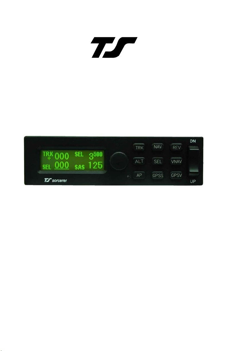
Mode and Data
Display
This display normally
shows operating modes and
associated numerical data. It is
also used to display setup mode
screens and the setting of
associated numerical data.
When displaying operating
modes, the left side shows
lateral data and the right side
shows vertical data. (See figure
below) The upper left display
labeled
electronic DG slaved to GPS
track. When the GPS track is
not available
replaced by
means the autopilot now uses
its internal gyros for bank angle
control. The lower left display
labeled
direction of flight when in the
standard track mode. When in
the gyro mode, the lower left
shows the current selected bank
angle. The upper right display
shows altitude or selected
altitude, and the lower right
display shows either selected
vertical speed or selected
airspeed.
the left and right hand display
area is used to show pitch trim.
This display consists of four
TRK shows the
TRK will be
BANK, which
SEL shows the selected
The vertical space between
horizontal bars spaced
vertically as the rungs on a
ladder, and are made to move
up or down when the aircraft is
in need of being trimmed.
In the upper left where
direction is shown, a flashing
indicator is present in the center
left of the display. When there
is no GPS signal present the
display will show
NO GPS.
When there is no GPS po sition
information the indicator will
be a flashing period, and the
display will show
NO FIX.
Once GPS position data
becomes valid the indicator will
be a flashing asterisk, and the
display will show
GPS OK. If
GPS flight plan information is
being received over the serial
channel or if GPS steering
information is being received, a
flashing plus sign will indicate
the presence of a useable
steering (GPSS mode) or
waypoint to waypoint (GPS
NAV mode) signal.
A cursor in the form of an
underline is shown beneath the
SEL numerals. This is used to
indicate that an underlined
number will be set by rotation
of the encoder knob.
3
Page 5

4
Controls
Switches labeled
[NAV] [REV] [SEL] [VNAV]
when depressed enter the
respective lateral and vertical
mode setup screens. When the
desired setup screen is
displayed, the numerical data to
be entered will be underlined.
The data is then set by rotating
the encoder knob and entered
by depressing and then quickly
releasing the knob. This will be
referred to hereafter as “enter”.
The [TRK] [ALT] [AP]
[GPSS] [GPSV] buttons do
not have setup screens; they
enter directly into the respective
modes.
Another means of entering
numerical data is the sequential
pressing of the vertical speed
rocker. Each ti me the rocker is
pressed, the vertical speed will
be changed in increments of
100 feet per minute. If the
vertical speed rocker is pushed
and held, the vertical speed will
slowly scroll up or down in the
desired direction. Still another
means of altering the display
presentation is engaging or
disengaging the autopilot. This
is accomplished by using the
[AP] switch on the
programmer. If GPS Steering
or Vertical GPS Steering is
available, the [GPSS] [GPSV]
switches will also engage the
autopilot. The control stick
switch located on the control
wheel or stick is yet another
means of engaging the
autopilot. The control stick
switch serves a dual purpose.
Momentary closure will
disengage the autopilot. If the
switch is held closed more than
two seconds, the autopilot will
engage upon release. This
means that in addition to
disengaging the autopilot, this
switch also provides the
function referred to as Control
Wheel Steering in that the
autopilot synchronizes to both
direction and vertical speed
upon being engaged.
Lateral Modes
Upon being engaged, the
autopilot will be in the basic
lateral mode, and it will be
synchronized to the track being
flown at the time. (See figure
on page 3.) Note: The number
following
direction) is underlined,
meaning that rotation of the
encoder will select a new
ground track. Rotation of the
knob when it is not depressed
will cause 5° steps of
when it is depressed the steps
will be 1°.
If the autopilot is in another
lateral mode, pushing the
[TRK] button will enter the
basic track mode.
When an external heading
source (DG or HSI) is present,
pressing [TRK] will toggle
between the
track mode. When in the
DG mode the heading “bug”
within the external DG or HSI
SEL (Selected
SEL and
EXT DG and the
EXT
Page 6
will be used to control
direction.
GPS Steering/GPS
Nav Mode
Pressing the [GPSS]
button will enter either GPS
NAV or GPSS mode
depending on which, if either,
steering signal is available to
the autopilot.
In GPS NAV mode the
autopilot follows a flight plan
programmed into the GPS. The
autopilot will however overfly
each waypoint prior to turning
and intercepting the course line
to the next waypoint.
In the GPSS mode the
autopilot follows lateral
steering or bank commands
generated by a navigation
system (EFIS or GPS). If there
is a GPSS signal present, the
autopilot can also be engaged
with [GPSS] button, and it will
engage in the GPSS mode.
NOTE: If there is not a
GPS NAV or GPSS signal
present the [GPSS] button
will not function.
5
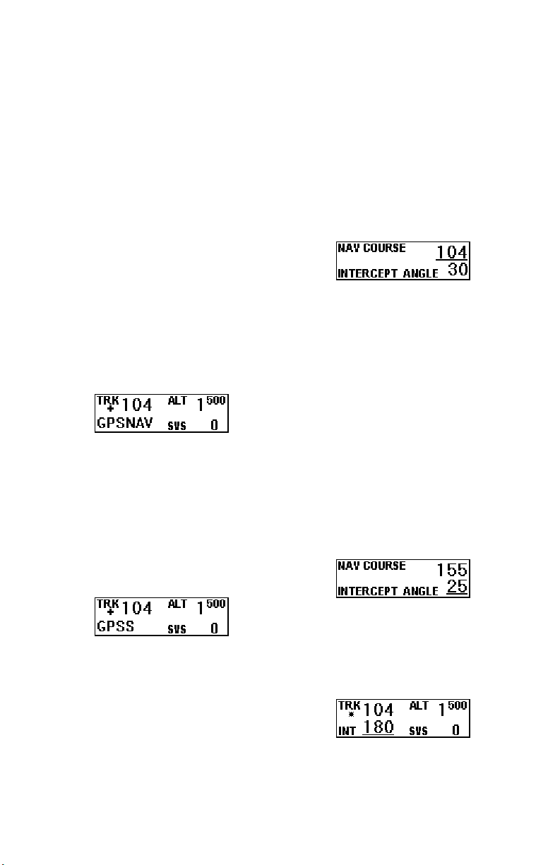
NAV/LOC Course
Mode
Pressing the [NAV] button
will bring up the
LOC COURSE setup screen
or
depending on which is selected
by the navigation receiver. The
setup screen for this mode is
shown below.
The course numerals are
underlined. This means that the
VOR/LOC course is to be set by
rotating the encoder. As the
encoder is rotated, knob out
equals 5° steps while knob in
equals 1° steps. When course
has been set press enter. The
cursor (underline) will now
move to intercept angle. The
default value will be 30°. The
intercept angle can be set from
15° to 45° by rotation of the
encoder knob. When the
desired intercept angle is set,
press enter.
The selected intercept
angle is now converted to an
intercept direction according to
which side of the course the
aircraft is on.
NAV COURSE
Page 7

Also, intercept direction is
underlined which means it can
be adjusted. With this feature
the system is in a selected
direction mode until the on
course turn (tracking phase) is
initiated. During the intercept
phase of the approach, the
lower left display will alternate
between
INT and NAV or LOC
depending on which mode has
been selected. When the
aircraft is established on the
inbound portion of the
approach, the lower left display
will indicate the selected
course.
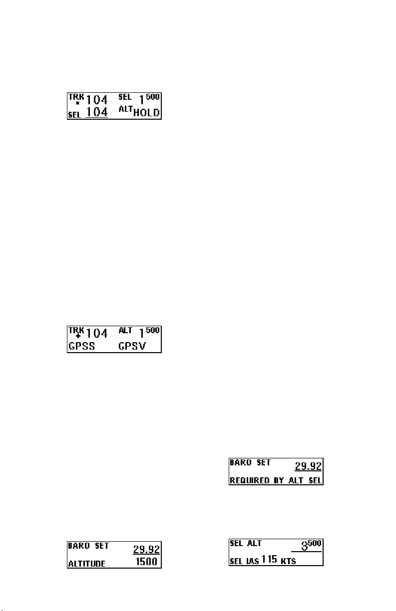
If the above is LOC
COURSE and glide slope is
present (ILS), flying below the
glide slope in ALT HOLD
mode will arm the glide slope
coupler. When this occurs, the
display will be as shown below:
When the Glide slope is
intercepted, the display will be
as shown below:
When glide slope coupling
is terminated, by entering either
the ALT
HOLD or SVS
(selected vertical speed) mode,
the lateral mode will switch
LOC COURSE to TRK
from
6
mode. The selected track will
be the same as the inbound
course.
NOTE: When coupled to
the glide slope, one push of
the VS rocker in either
direction will command a 500
fpm climb.
REV Course Mode
Click the [REV] button to
enter the
REV COURSE setup
screen. This refers to flying the
localizer or VOR
in the reverse
direction. Operation of this
mode is the same as
COURSE or LOC COURSE
except that there will be no
glideslope coupling.
Gyro Back-Up Mode
The lateral modes
previously described are based
on GPS track being present.
When GPS is lost, the autopilot
uses its internal gyros for bank
control, and
BANK. This mode is only
with
a backup and would seldom be
needed; however, it does
provide a means of selecting a
desired bank angle, and a means
of adjustment if the aircraft
turns when zero bank is
selected. If an external heading
source (HSI or DG) is present,
EXT DG mode remains
the
functional, and if the GPSS or
GPSV signal source is
functional, the GPSS and
GPSV modes will also be
functional. The remaining
modes,
TRK is replaced
NAV COURSE and LOC
NAV
Page 8

COURSE navigation should not
be used when GPS track is
absent. The VNAV mode will
also not be functional without a
GPS signal. When in the gyro
backup mode the number
displayed below
selected bank angle. Rotating
the encoder knob will move the
selected bank angle one degree
at a time up to five degrees, the
bank angle is then selectable in
five degree steps up to 30
degrees.
BANK is the
If the aircraft continues to
turn when a bank angle of zero
degrees has been selected, push
in on the encoder and the
display changes to show a
adjustment. This adjustment is
selectable in increments of 0.2
degrees per minute up to ten
degrees per minute in either
direction. Every time the trim
is adjusted it will add the
displayed number to the current
trim adjustment.
TRIM
Yaw Damper
The Yaw Damper can be
used whether or not the
autopilot is engaged. It
automatically comes on when
the autopilot is engaged. When
the autopilot is not engaged the
Yaw Damper can be toggled on
7
or off by pressing the [TRK]
button. If the autopilot is not
engaged, the yaw damper will
automatically disengage at the
user selectable minimum
airspeed. When the autopilot is
not engaged, and the yaw
damper is engaged the display
will be as shown below.
Vertical Modes
When the autopilot is
engaged, it will synchronize to
the vertical speed being flown
at the time, and thus will be in
the basic vertical speedoperating mode (see figure on
page 3). While in this basic
vertical speed mode, the upper
right section of the display
shows altitude and the lower
right section shows
(selected vertical speed). This
mode is also entered by
pressing either end of the
vertical speed rocker. If the
system is in transition to a
selected altitude pressing the
appropriate direction of the
vertical speed rocker will
switch from airspeed to vertical
speed. It will not cancel the
selected altitude, unless the
selected vertical speed is in the
opposite direction.
Altitude Hold Mode
Press [ALT] to select ALT
HOLD mode. The selected
altitude will be to the nearest
100 feet as viewed on the
SVS
Page 9
digital altimeter. For example,
pressing enter between 4950
and 5050 will select 5000.
Vertical GPS
Steering Mode
Pressing the [GPSV]
button will enter vertical GPS
steering mode. In the GPSV
mode the autopilot follows
vertical steering commands
generated by a navigation
system (EFIS or GPS). If there
is a vertical steering signal
present, the autopilot can also
be engaged with [GPSV]
button, and it will engage in the
GPSS and GPSV mode.
When in the GPSV mode, the
display will be as shown below.
NOTE: If there is not a
vertical GPS steering signal
present the [GPSV] button
will not function.
Barometer set
NOTE: (SORCERER ONLY)
The barometer must be set
prior to using the altitude
select feature. To enter the
BARO SET screen, press and
hold [SEL], for approximately
three seconds. The display will
show the following screen.
8
Rotate the encoder to
match the displayed number to
the current barometer setting;
the default will always be
29.92. When this is done press
enter. If the displayed altitude
is not correct, adjust it by
rotating the encoder knob.
Press enter to accept the current
altitude and exit the barometer
set mode.
When the autopilot is
engaged and in altitude hold,
upon exit of the barometer set
page the autopilot will climb or
descend to the current selected
altitude.
Altitude Select Mode
NOTE: (SORCERER ONLY)
Pressing [SEL] will display the
SEL ALT set up screen.
The barometer must be
set prior to using the altitude
select feature. If the
barometer is not set prior to
attempting to enter the
altitude select screen the
display will show the
following screen. To set the
barometer see Barometer set
in the previous sec tion.
If the barometer set has been
done the display will show the
following screen.
Page 10
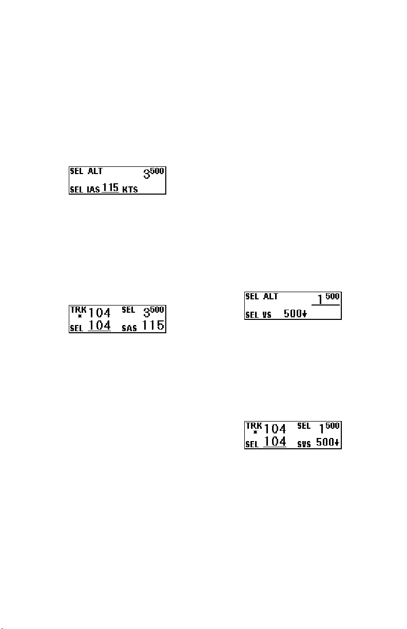
At this screen the SEL ALT
numerals are underlined so that
rotation of the encoder selects
the target altitude. When this is
done press enter.
If a higher altitude has been
selected, the pre-set (best-cruise
climb) air speed is now
displayed and underlined.
This value can be modified
by rotating the encoder knob.
When air speed has been set,
press enter and the altitude
transition will begin. The
autopilot will then revert to the
normal flight display.
Also, SEL direction will
again be underlined. Both
selected altitude and air speed
can be modified while in
transition. Press and release the
encoder knob once and the
underlined cursor moves to
selected altitude. Pressing a
second time moves it to air
speed and a third time returns it
to direction, or after a short
period of time it will return
automatically to direction. If
the selected airspeed is
adjusted, the airspeed will then
change at a constant rate from
its initial value to the selected
value at which point it will
9
cease moving with no
overshoot.
Finally, because the
vertical speed rocker is always
active, the climb to a new
altitude can be changed from
airspeed to vertical speed and
the rate adjusted, by pressing
the appropriate direction on the
vertical speed rocker the
required number of times.
If a lower altitude is
selected, the set-up screen will
be as shown below in which a
default downward vertical
speed of 500 Fpm is shown
when the selected altitude
differs from the present by
more than 500 feet.
When the new altitude has
been selected and entered the
downward transition will begin
at 500 fpm. Pressing the
appropriate direction on the
vertical speed rocker will
modify this value.
VNAV Mode
NOTE: (SORCERER ONLY)
Pressing [VNAV] will display
SEL ALT set up screen.
the
NOTE: The barometer
must be set prior to using the
VNAV feature. If the
barometer is not set prior to
attempting to enter the
Page 11

altitude select screen the
display will show the
following screen. To set the
barometer see Barometer set
on page 8.
If the barometer set has
been done the display will show
the following screen.
NOTE: If there is not a
GPS signal present, the
[VNAV] button will not
function.
At this screen the
numerals are under lined so that
rotation of the encoder selects
the target altitude. When this is
done press enter.
Once the desired altitude
has been entered the
numerals are underlined so that
rotation of the encoder now will
select the distance, in nautical
miles, in which the selected
altitude will be reached. Click
the knob to enter the distance
and begin the transition to the
selected altitude. The autopilot
will now revert to the normal
flight display.
As in the altitude select
mode, the selected altitude and
SEL ALT
DIST
10
selected distance can be
adjusted by clicking the knob to
move the cursor first to the
selected altitude, then to the
selected distance. A third click
will click will return the cursor
to direction, or after a short
period of time the cursor will
return automatically to
direction.
Minimum Airspeed
Any time the autopilot is
engaged, and the airspeed falls
to the minimum airspeed
setting, the autopilot will begin
to flash
below.
MIN AS, as shown
Maximum Airspeed
Any time the autopilot is
engaged, and the airspeed
reaches the maximum airspeed
setting, the autopilot will begin
to flash
below.
MAX AS, as shown
Stopping the
Transition to a
Selected Altitude
Once the aircraft is in
climb or descent to a selected
altitude, the process can only be
stopped by entering the
ALTHOLD mode. This is
accomplished by arriving at the
selected altitude or by selecting
ALTHOLD mode by
the
clicking the [ALT] button.
Page 12
11
Additional Operating Instructions
Initializing the
Autopilot
The au top ilot master switch
should be in the off position
when the engine is started.
Aircraft electrical systems can
generate voltage transients
during an engine start, and like
other avionics systems, the
autopilot should not be
subjected unnecessarily to these
conditions. After start up, turn
on the autopilot master switch
and hold the aircraft stationary
as the internal gyros are
initialized. This takes
approximately ten seconds
during which time the display
will show the words PWR UP
in the lower right. NOTE: The
aircraft must be stationary
for the first ten seconds after
power is applied to the
autopilot.
When initializing is
complete PWR UP will change
to AP OFF.
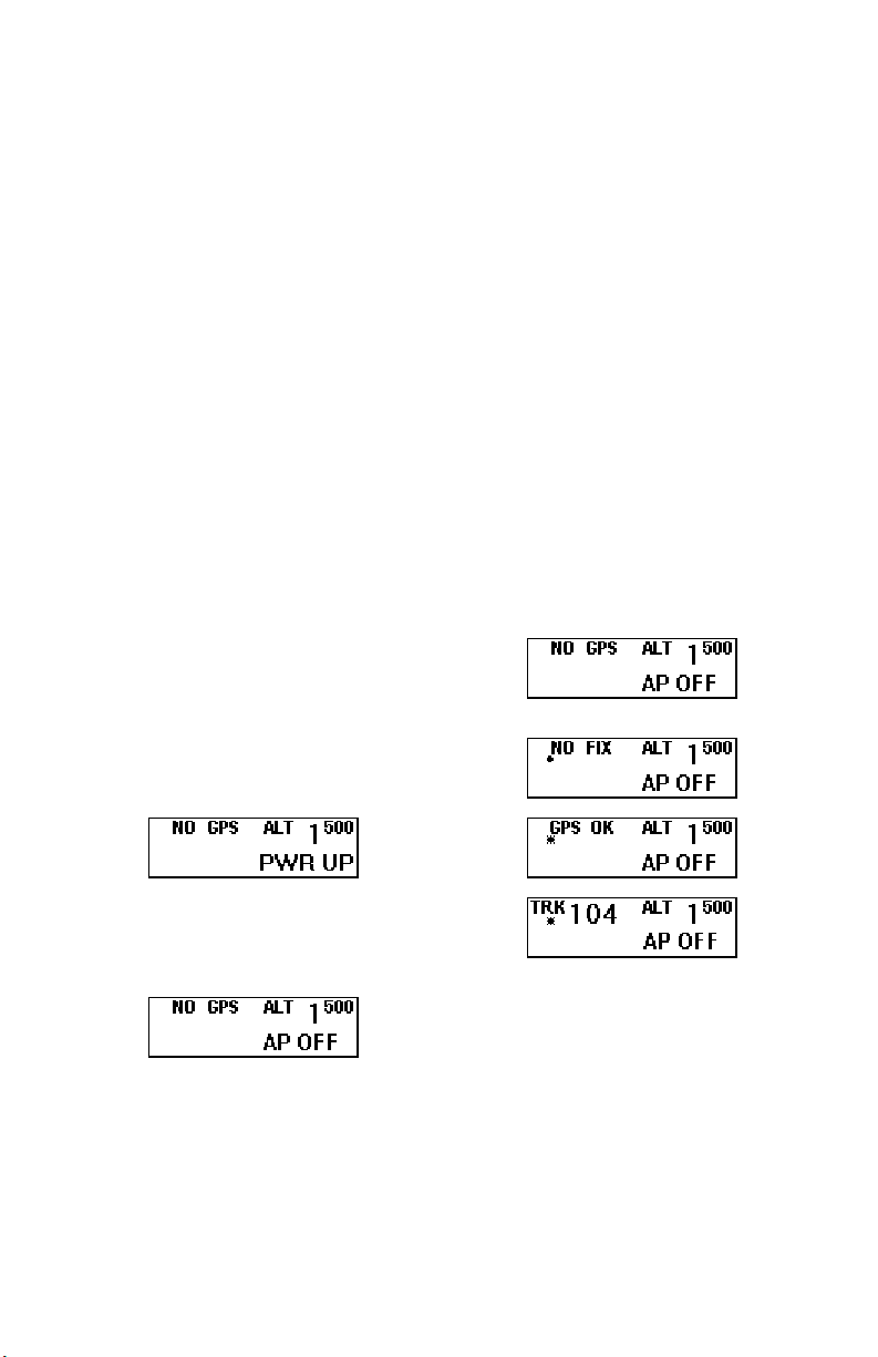
GPS Acquisition
If there is no GPS signal
the top left portion of the
display will read
GPS signal is present, but
satellites have not yet been
NO GPS. If a
acquired, the upper left portion
of the display will read
with a flashing
the GPS does obtain a fix, the
period will be replaced by an
asterisk and the display will
switch to show
flashing *
that when a certain velocity is
attained
followed by the current track.
This happens at approximately
10 Knots groundspeed as
detected by GPS and will even
occur at rapid taxi speeds. The
four possible screens are shown
below.
• below. When
GPS OK with a
below. This means
TRK will appear
NO FIX
Altitude Select with
AP Off
NOTE: (SORCERER ONLY)
If a target or assigned
altitude is known prior to take-off
this altitude can be set while on
the ground. As with the AP on,
pressing [SEL] will display the
SEL ALT setup screen. The
Page 13

12
procedure is to select the desired
altitude and then press enter.
NOTE: The Barometer
must be set prior to
attempting to enter the
altitude select screen.
The display will show the
selected altitude even though the
autopilot is still off. This will
serve as a reminder that the
autopilot will climb to the
selected altitude when engaged.
It will not climb at a selected
airspeed, but will default to a
vertical speed of 500 fpm. This
can be adjusted with the vertical
speed rocker as usual.
Gyro Set
When the initializing has
been done correctly, the gyros
should already be centered at the
time of take off. If confirmation
of this is desired, with the aircraft
stationary on the runway,
pressing and holding the encoder
knob will put the gyros in the fast
centering mode. The knob
should be depressed for
approximately 10 seconds during
which time the words
will be displayed.
SET
GYRO
Engaging the
Autopilot
Since the autopilot
synchronizes to
the vertical speed at the time of
engaging should be a value that
can be sustained. Otherwise
airspeed will diminish as the
vertical speed,
aircraft attempts to sustain
vertical speed. As
diminishes to the pre-set
minimum it will hold this value
and thus prevent a stall.
When aircraft vertical speed
is less than approximately 450
feet per minute, the autopilot will
initially select zero vertical speed.
The vertical speed rocker can be
used to change the initial value if
desired.
airspeed then
Setting Pitch Trim
The pitch servo contains a
torque sensor that sends a signal
to the computer when the up or
down force greater than a
threshold value is required to fly
a selected flight condition. When
this signal indicates an out-oftrim condition that persists in one
direction for more than a few
seconds, the three moving
horizontal bars will come into
view and move according to the
direction in which trim is
required. The pilot is then
required to operate the trim
control (electric or manual) so as
to bring the system to neutral
trim. With mechanical trim this
is easily done, but with electric
systems it may be necessary to
develop a technique. If the trim
is slow enough, the pilot has
plenty of time to react when the
bars disappear before the trim
condition is reversed. With a fast
trim it will be necessary to tap or
pulse the trim button so that it
will be slow enough to turn it off
before going too far. When a
reversal takes place, a slight tap
in the reverse direction may be
required to get the bars to stay
Page 14

off. Finally, when the bars have
been made to disappear and there
has been no speed change, the
bars can be ignored if they
reappear if it is known the aircraft
is close to being in trim.
Power Loss
If there is a momentary loss
of electrical power, the autopilot
will disengage. When this
happens it is necessary to do a
GYRO SET before re-engaging
the autopilot. To accomplish this,
the aircraft must be held very
straight during which time the
encoder knob is pressed to do
GYRO SET. After this, engage
the autopilot and note the extent
to which
If this is more than 15° repeat the
gyro set procedure. The
difference between
will be reduced at the rate of 8°
per minute by the automatic gyro
centering system within.
TRK differs from SEL.
TRK and SEL
13
Page 15

Sorcerer Setup Procedure
Lateral Setup
The lateral setu p co nsists of
setting activity, torque, serial
baud rate, and various
configuration parameters. To
enter the setup mode, press and
hold the [TRK] button for two
or more seconds, until the first
setup screen appears. This
screen shows the current value
for the activity, with an
underline under the present
setting of activity. A typical
screen might show:
The underlined number is
set by rotating the encoder
knob. Turn this knob to set the
activity level to the desired
value for the particular aircraft.
Any value between 0 and 24
may be chosen. In this example,
the value of 1 will be selected.
Activity should be set so as to
not be excessive in turbulence
and yet sufficient to fly without
hunting in still air. (Any lost
motion or play between the
servo and the control surface
can cause hunting in still air).
Once the LAT ACTIVITY
has been set to the desired
value, push the up control on
the vertical speed rocker to
enter the selected value into
storage, and advance to the next
setup screen.
14
In a manner similar to
activity, use the encoder knob to
select the desired value of roll
servo torque. This value should
be between 8 and 12. A default
value is set at the factory but
may need to be modified to suit
a particular aircraft. The value
chosen should be sufficient to
fly the aircraft, but not so much
that it is difficult to override the
autopilot if necessary.
Having selected the desired
LAT TORQUE level, again
push the up control on the
vertical speed rocker to enter
the selected value into storage,
and advance to the next setup
screen. If the need arises to
move to a previous setup screen
pressing the down control on
the vertical speed rocker will
move to the previous screen.
Likewise, clicking the encoder
knob in any setup screen will
exit the setup mode. The next
setup screen is shown below.
The value shown represents
the speed of the primary RS232 interface to the external
GPS unit. By default at the
factory the BAUD is set to
9600, as that is the most
commonly used value.
Page 16

15
However, it may be set to any
of 600, 1200, 2400, 4800, or
9600 baud. Consult the manual
for the GPS unit and follow its
setup instructions to determine
its setting and set the baud rate
of the autopilot to the same
value. The autopilot will
recognize NMEA-0183
protocol, Garmin protocol, or
Apollo GX50/GX60 protocol
(moving map output).
Once the desired baud rate
has been selected, again push
the up control on the vertical
speed rocker to enter the
selected value into storage, and
advance to the next setup
screen, which is shown below.
The BANK ANGLE setup
screen allows a low, medium, or
high setting. This will limit the
autopilots maximum bank angle
to approximately 13 degrees at
the low setting, approximately
18 degrees at the medium
setting, and approximately 24
degrees at the high setting.
Once the desired maximum
bank angle has been selected,
again press the up control on the
vertical speed rocker to advance
to the next setup screen, which
is shown below.
The next setup screen is
MICROACTIVITY. This
setting is to be left at zero
unless advised by the factory.
Press the up control on the
vertical speed rocker to advance
to the next setup screen, which
is shown below.
The next setup screen is
GPSS GAIN. This setting
should be left at 16 unless
advised by the factory. Press
the up control on the vertical
speed rocker to advance to the
next setup screen, which is
shown below.
Th is setup screen is to turn
the speech annunciation on and
off. If the speech is turned off,
the autopilot will give a series
of alerter tones for important
information. If the speech is
turn on, there will be a voice
annunciation for important
information. Once this has been
set, press the up control on the
vertical speed rocker to advance
to the next setup screen, which
is shown below.
The next setup screen is for
AUDIO LEVEL. While this
screen is displayed, the
autopilot will send an audio
Page 17

tone to the audio system.
Adjust the value between 0 and
16 for the desired volume.
Once the audio level has been
set, press the up control on the
vertical speed rocker to advance
to the next setup screen, which
is shown below.
The next setup screen is the
external DG/HSI setup screen.
Use the encoder to select either
Y (yes) or
whether an external DG or HSI
is connected to the system.
Press the up control on the
vertical speed rocker to advance
to the next setup screen, which
is shown below.
Answer Y (yes) or N (no)
to indicate whether or not a yaw
damper is present. If N is
selected, this is the final lateral
setup mode. Press enter to exit
the lateral setup mode. If Y is
selected push the up control on
the vertical speed rocker to
advance to the next setup mode,
which is shown below.
If the YAW DAMPER?
was answered with Y, then the
next setup screen will be for YD
LEVELING. This is the fine
adjustment for the leveling of
N (no) depending on
16
the yaw damper module. The
value for leveling is adjustable
from -8 to 8 and is used as
necessary to have the yaw
damper keep the aircraft
slip/skid indicator (ball)
centered when the yaw damper
is engaged and the autopilot is
flying the aircraft straight and
level. When adjusting this
value, allow a few seconds for
the yaw damper to respond to
each new value setting. Once
the yaw damper leveling has
been set, push the up control on
the vertical speed rocker to
advance to the final setup
screen, which is shown below.
The final setup screen is for
yaw damper activity. The yaw
damper activity functions
exactly like the lateral and
vertical activity settings. This
setting is adjustable from 0 to
12, where zero is the lowest
activity and 12 is the highest
activity. Once the activity has
been set, push enter to exit the
lateral setup mode.
Pitch Setup
The pitch (vertical) setup
consists of setting activity and
torque in a manner similar to
that done for the aileron servo
in the lateral setup. To enter the
vertical setup mode, press and
hold the [ALT] button for two
or more seconds, until the first
Page 18

setup screen appears. This
screen shows the current value
for the activity with an
underline under the present
setting of activity. A typical
screen might show:
Turn the encoder knob to
set the activity level to the
desired value for the particular
aircraft. Any value between 0
and 24 may be chosen.
Once activity is set to the
desired value, press the up
control on the vertical speed
rocker to advance to the next
setup screen, which is shown
below.
In a manner similar to
activity, use the encoder knob to
select the desired value of pitch
servo torque. This value should
be between 8 and 12. A default
value is set at the factory but
may need to be modified to suit
a particular aircraft. The value
chosen should be sufficient to
fly the aircraft, but not so much
that it is difficult to override the
autopilot if necessary.
Having selected the desired
torque level, again press the up
control on the vertical speed
rocker to advance to the next
setup screen, which is shown
below.
17
Use the encoder knob to
select the minimum airspeed at
which the autopilot will fly the
aircraft. This speed should be a
safe margin above a stall. Press
the up control on the vertical
speed rocker to advance to the
next setup screen, which is
shown below.
Use the encoder to select
the maximu m airsp eed at whi ch
the autopilot will fly the
aircraft. This should be safely
below red line, but above cruise
speed. Once this value has been
set, press the up control on the
vertical speed rocker to advance
to the next setup screen, which
is shown below.
Select, using the encoder
knob, the default value most
commonly used for a climb to a
selected altitude. Press the up
control on the vertical speed
rocker to advance to the next
setup screen, which is shown
below.
Page 19

18
The next screen in the pitch
setup sequence allows
adjustment to compensate for
the lag (delay) in the aircraft’s
static system. Select the lowest
value over the range 0 to 2
which results in the elimination
of “hunting” in the altitude hold
mode. This adjustment should
be done in still air at cruise
airspeed. Press the up control
on the vertical speed rocker to
advance to the next setup
screen, which is shown below.
The next setup screen is
MICROACTIVITY. This
setting is to be left at zero
unless advised by the factory.
Press the up control on the
vertical speed rocker to advance
to the final setup screen, which
is shown below.
This setting in most cases
will not need to be adjusted. If
this is set to Y (yes), then the
pitch servo will have a higher
resolution and take smaller
steps. However, it will also
have less available torque. This
setting should be left at N (no)
unless it is observed that the
nose moves up and down very
slightly in very still air. Once
this setting has been completed,
push enter, to exit the vertical
setup mode and return to the
normal flight screen.
This concludes the vertical
setup portion of the Sorcerer
autopilot.
Page 20

(5-06)
Printed in U.S.A.
TruTrak Flight Systems, Inc.
 Loading...