

Page 1
Operating Handbook
For
SORCERER AUTOPILOT
TRUTRAK FLIGHT SYSTEMS
1500 S. Old Missouri Road
Springdale, AR 72764
Ph. 479-751-0250 Fax 479-751-3397
www.TruTrakap.com
Page 2

Table of Contents
Operating Instructions
General Introduction ................................................. 3
Autopilot Power-up ................................................... 4
Mode and Data Display ............................................. 4
Controls .................................................................... 9
Lateral Modes ........................................................... 9
GPS Steering/GPS Nav Mode ................................... 9
NAV/Loc Course Mode ............................................ 10
Reverse Course Mode ............................................... 11
Gyro Back-Up Mode ................................................. 11
Yaw Damper............................................................. 12
Vertical Modes ......................................................... 12
Altitude Hold Mode .................................................. 13
Vertical GPS Steering Mode ..................................... 13
Barometer Set ........................................................... 13
Altitude Select Mode ................................................ 14
Stopping the Transition to a Selected Altitude ........... 15
VNAV Mode ............................................................ 15
Minimum Airspeed ................................................... 15
Maximum Airspeed .................................................. 16
Additional Operating Instructions
Initializing the Autopilot ........................................... 16
GPS Acquisition ....................................................... 16
Altitude Select with AP Off....................................... 17
Gyro Set ................................................................... 17
Engaging the Autopilot ............................................. 17
Setting Pitch Trim ..................................................... 17
Power Loss ............................................................... 18
GPSS Missed Approach Function.............................. 18
Setup Procedure
Lateral Setup............................................................. 5
Pitch Setup ............................................................... 7
Page 3

3
General Introduction
The TruTrak autopilot can be defined as being an orthogonal rate system.
This means that gyroscopic rate sensors sense motion about each of the
major axes (roll, pitch and yaw). These sensors generate the fast signal
responses necessary to create an autopilot with the best possible dynamic
performance.
To fly an aircraft well about the axis controlled by the ailerons, velocity
of aileron movement must be directly proportional to the rate of roll for small
movement. This means that aileron position corrections do not lag behind
motion of the craft about the roll axis. Aileron control systems that use a
turn coordinator, which senses twice as much azimuth as roll rate, cannot do
this. Instead, yaw disturbances in turbulence cause undesired aileron
movement. In some aircraft this effect is so severe that the controls may
even momentarily move in the wrong direction.
The goal at TruTrak is to create systems with the very best dynamic
performance available—systems that do not need to be disengaged in
turbulence, but instead provide function when needed most.
The complete TruTrak autopilot system combines all the electronic and
sensing elements needed for the roll and pitch functions within a single
panel-mounted programmer/computer package. A rate-gyro-controlled yaw
damper can be added to the system.
Basic directional control is provided by digital selection of a GPS track.
This replaces heading selection on the DG and eliminates drift as well as
crosswind correction. In the GPS steering mode of operation, the system
responds to digital guidance information to fly a complex navigation
program.
The vertical portion of the system contains a digital altimeter and
associated altitude selector with selectable increments as small as fifty feet.
Altitude transitions can be made by airspeed, vertical speed, or horizontal
distance (VNAV) selection. If an upward vertical speed is selected which is
beyond the capability of the aircraft, there will be no stall. Instead, the
autopilot will cause the aircraft to climb at a pre-set minimum safe airspeed.
This is the only known system to provide this safety feature.
For any set of features all TruTrak computers are identical. Servos
likewise are identical in velocity response. Servos do differ according to
total torque required. By providing setup functions in the programmer for
system activity and torque, one TruTrak programmer-servo combination can
fly any aircraft.
As a starting point in understanding how to operate the TruTrak system,
the following describes the presentation of data, the operating controls, and
the procedures for selecting modes of operation.
Page 4
4
Autopilot Power Up
The autopilot master switch should be in the off position when the
engine is started. Aircraft electrical systems can generate voltage
transients during an engine start and like other avionics systems, the
autopilot should not be subjected unnecessarily to these conditions.
After start up, turn on the autopilot master switch and keep the aircraft
stationary as the internal gyros are initialized. This takes approximately
ten seconds during which time the display will show the words PWR UP
in the lower right. When initializing is complete PWR UP will change
to AP OFF.
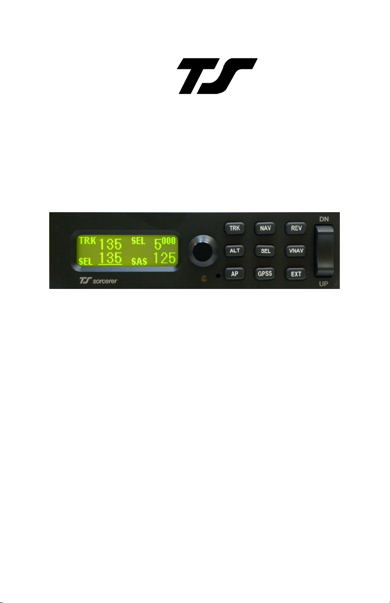
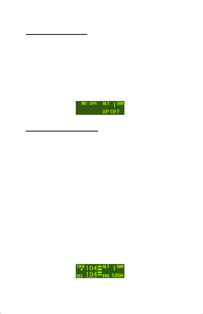
Mode and Data Display
The display shows operating modes and associated data. It is also
used to display setup mode screens and their values. When displaying
operating modes, the left side shows lateral data and the right side shows
vertical data. NO GPS will be displayed in the top left of the display
when no GPS signal is detected. A flashing period will appear when a
GPS signal is detected, but no position information is available. The
words NO FIX will be displayed. Once GPS position data becomes valid
a flashing asterisk will appear and the display will show GPS OK. If
GPS flight plan information is being received over the serial channel or if
GPS steering information is being received, a flashing plus sign will be
shown in place of the asterisk.
The upper left display is labeled TRK, showing the electronic DG
slaved to GPS track. When the GPS track is not available, TRK will be
replaced by BANK. This means the autopilot is using its internal gyros
for bank angle control. The lower left display labeled SEL shows the
selected GPS ground track when in the standard track mode. When in
the gyro mode, the lower left shows the current selected bank angle. The
upper right display shows altitude or selected altitude, and the lower right
display shows either selected vertical speed or selected airspeed.
Underlined numbers indicate a value that can be adjusted by rotating
the knob. A sample of the display is shown below.
Page 5
5
Sorcerer Setup Procedure
In the Sorcerer setup screens, pressing VS UP on the rocker switch
will advance the page to the next setup screen. Pressing VS DN will
return to the previous screen. All values are changed by rotating the
knob. Pressing the knob will exit the setup mode.
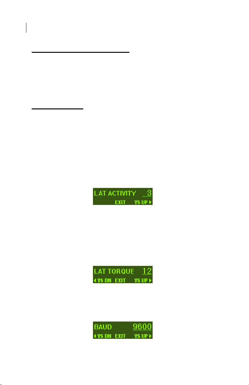
Lateral Setup
To enter the lateral setup mode, press and hold the TRK button for
two or more seconds until the first setup screen appears. This screen
shows the current value for the LAT ACTIVITY. Any value between 0
and 24 may be chosen. In this example, the value of 3 is selected. The
higher the number is set, the faster the servo moves the control system.
Too low of a setting will cause hunting, too high of a setting will cause
hunting and the servo to be overactive and jitter. (Any lost motion or play
between the servo and the control surface can cause hunting in still air).
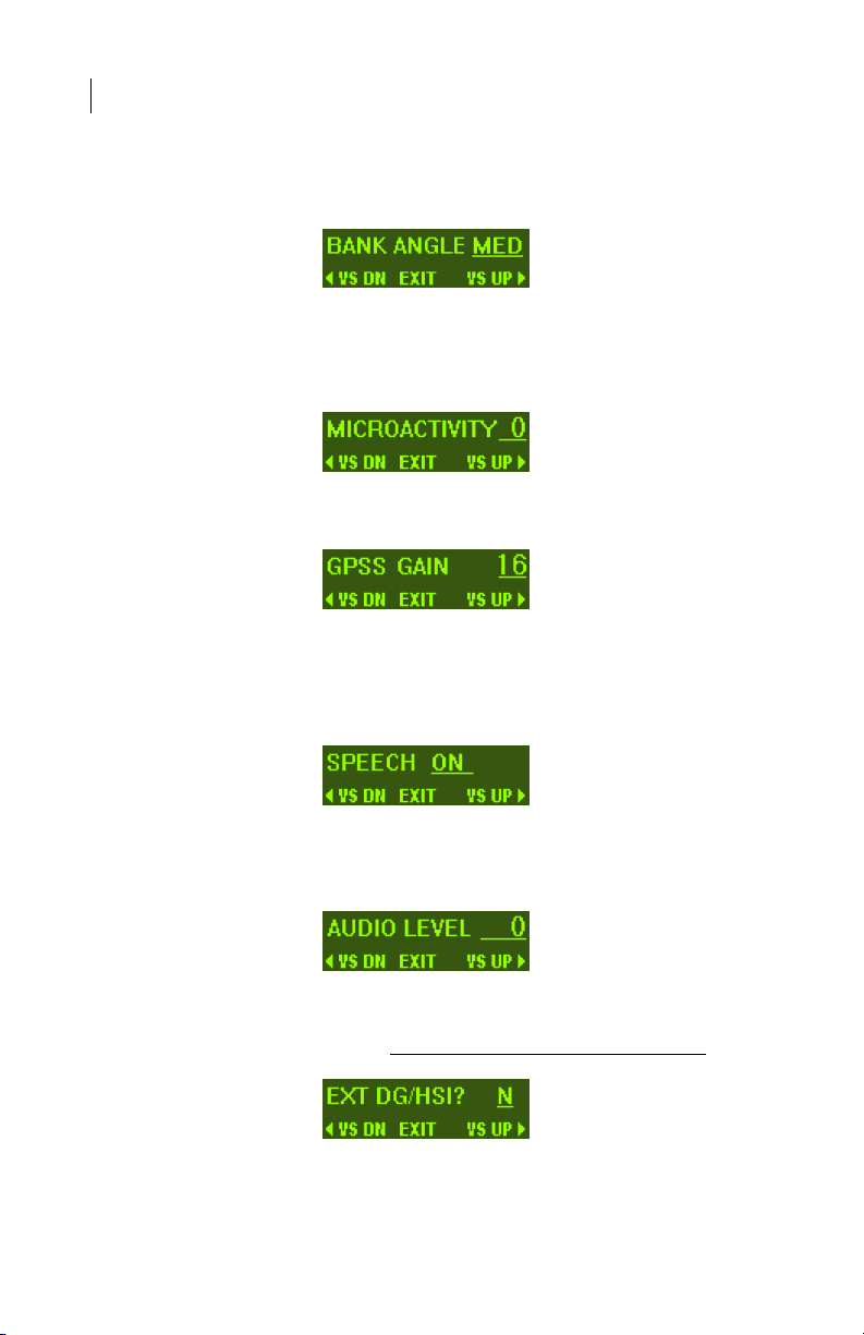
The next setup screen is for adjusting LAT TORQUE. This determines
how much torque the roll servo is allowed to apply with 12 being the
maximum. A default value of 12 is set at the factory but may need to be
modified to suit a particular aircraft or pilot. Trutrak recommends a
setting of 12 for all aircraft. If the torque setting is too low the AP may
not be able to control the aircraft in all flight conditions. This could
cause the aircraft to drift off selected track.
The next screen shows the RS-232 input BAUD rate setting. The
default setting is 9600. Consult the Sorcerer installation manual for
information on how to setup some GPS receivers to properly
communicate with the Sorcerer AP.
Page 6
6
The next screen shows the BANK ANGLE adjustment. It is
adjustable to LOW, MED, or HI. This will limit the AP bank angle to
approximately 13°, 18°, and 24° respectively. This setting has no effect
on the GPSS mode. It only affects GPS TRK and GPS NAV modes.
The next screen is the MICROACTIVITY. This setting is used
in cable controlled systems to remove any slack or lost motion
introduced by the cables. This setting should be left at zero unless
advised by the factory.
Advance to the next setup screen. This is the GPSS GAIN
setting. This setting should be left at 16 unless advised by the factory.
The next setup screen is SPEECH. This setting turns the speech
annunciation on and off. If the speech is turned off, the autopilot will
give a series of alerter tones for important information. If the speech is
turned on, there will be a voice annunciation for important information.
The next setup screen is for AUDIO LEVEL. While this screen is
displayed, the autopilot will send an audio tone to the audio system.
Adjust the value between 0 and 16 for the desired volume.
The next screen is the EXT DG/HSI selection. Use the knob to
select either Y (yes) or N (no) depending on whether an external DG or
HSI is connected to the system. Leave setting at N for Garmin G3X.
The next screen is the YAW DAMPER selection. Select Y (yes)
or N (no) to indicate whether or not a yaw damper is present. If N is
Page 7

7
selected, this is the final lateral setup screen. Click the knob to exit the
lateral setup mode. If Y is selected push VS UP on the rocker to advance
to the next setup screen.
If the YAW DAMPER? was answered with Y, then the next
setup screen will be for YD LEVELING. This is the fine adjustment for
the yaw damper to maintain a ball centered condition. The value is
adjustable from -8 to 8 and is used as necessary to have the yaw damper
keep the aircraft slip/skid indicator (ball) centered when the yaw damper
is engaged and the autopilot is flying the aircraft straight and level.
When adjusting this value, allow a few seconds for the yaw damper to
respond to each new value setting.
The final setup screen is for yaw damper activity. The yaw
damper activity functions exactly like the lateral and vertical activity
settings. This setting is adjustable from 0 to 12, where 0 is the lowest
activity and 12 is the highest activity.
Vertical Setup
To enter the vertical setup menu, press and hold the ALT button for
two or more seconds until the first setup screen appears. This screen is
the VRT ACTIVITY adjustment. Any value between 0 and 24 may be
chosen. Choose a level that gives the best overall performance in all
modes of flight.
The next setup screen is for VRT TORQUE. Any value between 0
and 12 may be selected. A default value of 12 is set at the factory.
Page 8

8
Trutrak recommends a setting of 12; however the value may be
lowered to suit pilot comfort level.
The next setup screen is the MIN AIRSPD setting. This value is
displayed in knots Indicated Airspeed. This value should be set above
the clean stall speed of the aircraft, but not so high as to interfere with
maneuvering with the autopilot engaged.
The next screen displayed is the MAX AIRSPD setting. This value
is also displayed in knots Indicated Airspeed. It should be set safely
below the redline IAS of the airframe, but not so low as to interfere with
maneuvering with the autopilot engaged.
The next screen is the NORM CLIMB setting. This value is the
default indicated airspeed value selected when an altitude select is
entered above the current altitude.
The next screen is the STATIC LAG adjustment. This allows the
user to compensate for lag in the static system of the aircraft that causes
pitch oscillations in calm air. Select the lowest value over the range 0 to
2 which results in the elimination of “hunting” in the altitude hold mode.
This adjustment should be done in still air at cruise airspeed.
The next setup screen is MICROACTIVITY. This setting
should be left at zero unless advised by the factory.
The final screen is the HALF-STEP setting. Most of the time, this
setting will not need to be adjusted. When it is set to Y (yes), then the
pitch servo will have a higher resolution and take smaller steps.
However, it will also have less available torque. This setting should be
Page 9

9
left at N (no) unless the nose of the aircraft moves up and down very
slightly in very still air.
Push the knob to exit the setup menu.
Controls
The autopilot can be engaged in one of three ways; (1) Pushing the
AP button; (2) using the control wheel steering switch; (3) pressing the
GPSS button when a GPSS steering signal is available. The CWS
(Control Wheel Steering) switch is a momentary switch that should be
located on the stick/yoke for accessibility. When this switch is held
closed for 1.5 seconds from a disengaged state, the AP will engage. If
held closed for 1.5 seconds from an engaged state, the AP will enter
CWS mode. When the switch is momentarily closed (pressed and
released) from an engaged state, the AP will disengage.
Lateral Modes
When the autopilot is engaged it will synchronize to the current GPS
ground track. At this time the cursor will be located underneath the
numbers indicated by SEL on the display. The desired ground track can
be changed by rotating the knob to select a new track. Rotating the knob
will increment the selection by 5°. Pressing and holding the knob while
rotating will give 1° increments.
Pushing the TRK button at any time will return the autopilot to the
basic track selector mode.
When an external heading source (DG or HSI) is present and turned
on, pressing EXT will engage the external DG mode. When in this mode,
the heading “bug” within the external DG or HSI will control the
direction that the autopilot flies. For use with a Garmin G3X system, the
EXT button will still follow the heading bug of the PFD, but N must be
selected in the lateral setup menu.
GPS Steering (GPSS)/GPS Nav Mode/GPSV
Pressing the GPSS button will enter either GPS Nav or GPSS mode.
The type of steering command that is available will determine how the
autopilot will fly a flight plan programmed into the GPS.
Page 10

10
If only NMEA (RS-232) GPS information is available, the autopilot
will overfly each waypoint prior to turning and intercepting the course
line to the next waypoint.
With ARINC steering commands, the autopilot will follow lateral
steering or bank commands generated by a navigation system (EFIS or
GPS). This means the autopilot will round corners and not overfly the
course line to the next waypoint. The display will indicate when the
autopilot is in one of these modes by displaying GPSS in the bottom left
of the display.
The vertical GPS Steering mode (GPSV) is also engaged with GPSS
if the signal is present. If the autopilot is engaged during a climb or
descent, you must either zero the vertical speed with the rocker switch or
press the ALT to engage GPSV. The vertical steering can be decoupled
by selecting any other vertical mode. To re-engage the vertical steering,
press GPSS again, then press ALT or set the SVS to 0 using the rocker
switch.
NOTE: If there is not a steering signal present the GPSS button
will not function.
NAV/LOC Course Mode
Pressing the NAV button will bring up the NAV COURSE (VOR) or
LOC COURSE (ILS) setup screen depending on which is selected by the
navigation receiver. The setup screen for this mode is shown below.
Use the knob to adjust the selected NAV COURSE to the proper
value. Once set, press enter to advance to the intercept angle. This value
is adjustable from 15° to 45°. Rotating the knob will give 5° increments.
Press and hold the knob while rotating to get 1° increments. When the
desired intercept angle is set, press the knob to enter this mode.
The selected intercept angle is converted to an intercept direction
according to which side of the course the aircraft is flying.
In addition, intercept direction is underlined which means it can be
adjusted. With this feature the current direction can be adjusted (for
Page 11

11
example if being vectored) until the selected inbound course is crossed.
During the intercept phase of the approach, the lower left display will
alternate between INT and NAV or LOC depending on which mode has
been selected by the navigation receiver. When the aircraft is established
on the inbound portion of the approach, the lower left display will
indicate the selected course.
If the above is LOC COURSE and glide slope is present (ILS), flying
below the glide slope in ALT HOLD mode for a minimum of seven
seconds will arm the glide slope coupler. When this occurs, the display
will show:
When the Glide slope is intercepted, the display will show:
Glide slope coupling can be terminated by entering either the ALT
HOLD or SVS (selected vertical speed) mode. The lateral mode will
switch from LOC COURSE to TRK mode. The selected track will be the
same as the inbound course.
NOTE: When coupled to the glide slope, one push of the VS rocker in
either direction will command a 500 fpm climb and enter TRK mode.
REV Course Mode
Click the REV button to enter the REVERSE COURSE setup screen.
This refers to flying the localizer or VOR in the reverse direction.
Operation of this mode is the same as NAV COURSE or LOC COURSE
except that there will be no glide slope coupling.
Gyro Back-Up Mode
The lateral modes previously described are based on GPS track being
present. When GPS is lost, the autopilot uses its internal gyros for bank
control and TRK is replaced with BANK. This mode is only a backup and
would seldom be needed; however, it does provide a means of selecting a
desired bank angle, and a means of adjustment if the aircraft turns when
Page 12

12
zero bank is selected. The selected bank angle can be adjusted by
rotating the knob. The angle is selectable in 1° increments up to 5° in
either direction. After 5° the number will move in 5° increments up to a
total of 30° in either direction. If the aircraft makes a turn with 0° bank
selected, press and hold the knob to bring up the gyro trim adjustment.
This value is displayed in degrees per minute. It is adjustable in 0.2°/min
increments up to a total of 10° in either direction. Adjust the trim value
until the aircraft stops turning with 0° bank selected. If an external
heading source (HSI or DG) is present, the EXT mode remains functional,
and if the GPSS/GPSV signal source is functional, the GPSS and
VS(GPSV) modes will also be functional. The remaining modes, NAV,
LOC COURSE, and VNAV navigation should not be used when GPS
track is absent.
Yaw Damper
The Yaw Damper can be used whether or not the autopilot is
engaged. It automatically comes on when the autopilot is engaged.
When the autopilot is not engaged the Yaw Damper can be toggled on or
off by pressing the TRK button. If the autopilot is not engaged, the yaw
damper will automatically disengage at the user selected minimum
airspeed. When the autopilot is not engaged and the yaw damper is
engaged the display will be as shown below.
Vertical Modes
When the autopilot is engaged it will synchronize to the vertical
speed being flown at the time to the nearest 100’. At this time it will be
in the basic vertical speed operating mode. While in this mode, the upper
right section of the display shows altitude and the lower right section
shows SVS (selected vertical speed). This mode can also be entered by
pressing either end of the vertical speed rocker. If the system is in
transition to a selected altitude pressing the appropriate direction of the
vertical speed rocker will switch from airspeed to vertical speed. It will
not cancel the selected altitude unless the selected vertical speed is in the
opposite direction.
Page 13

13
Altitude Hold Mode
Press ALT to select ALT HOLD mode. The selected altitude will be
to the nearest 100 feet as viewed on the digital altimeter. For example,
pressing enter between 4950 and 5050 will select 5000.
Vertical GPS Steering Mode (see also GPSS)
If there is a vertical steering signal present when the GPSS mode
is active, and the autopilot is in altitude hold or zero vertical speed, the
autopilot will enter the vertical steering mode automatically. In the VS
(Vertical Steering) mode the autopilot follows vertical steering
commands generated by a navigation system (EFIS or GPS). NOTE: If
there is not a vertical GPS steering signal present the autopilot will NOT
have VS (GPSV) function.
On GPS WAAS/LPV Approach
Once the VDI has been above the center by one dot for at least 7 seconds
the VS mode will ARM, and the display will show:
As the VDI passes through center, the autopilot will couple to the virtual
glide slope, and the display will show that the autopilot is now coupled to
the virtual glide slope as below:
Barometer set
The barometer must be set prior to using the altitude select feature.
To enter the BARO SET screen, press and hold SEL, for approximately
three seconds. The display will show the following screen.
Rotate the encoder to match the displayed number to the current
barometer setting; the default will always be 29.92. When this is done
press enter. If the displayed altitude is not correct to the nearest 10 ft
adjust it by rotating the encoder knob. Press enter to accept the current
Page 14

14
altitude and exit the barometer set mode. The settings will not be saved
without pushing enter.
When the autopilot is engaged and in altitude hold, upon exit of the
barometer set page the autopilot will climb or descend to the current
selected altitude. *(Garmin G900X only), barometer value will be
automatically set if the G900X barometer value is adjusted.
Altitude Select Mode
Pressing SEL will display the SEL ALT set up screen. At this screen
the SEL ALT numerals are underlined so that rotation of the knob selects
the target altitude to the nearest 500’. Press and hold the knob while
turning to get 50’ steps. Press enter to save the value and advance the
cursor to the IAS or SVS setting.
If a higher altitude has been selected, the pre-set (NORM CLIMB)
airspeed is displayed. This value can be modified by rotating the knob.
When the airspeed has been set press enter and the altitude transition will
begin. The autopilot will then revert to the normal flight display. To use
vertical speed for the transition instead of airspeed, simply press the
vertical speed rocker switch in the desired direction to reach the target
rate.
If a lower altitude than current is selected by at least 500 ft, the
autopilot will allow you to choose a rate of descent. The default is 500
fpm. Use the vertical speed rocker to adjust the setting to the desired
value. Press enter after selecting the rate to return to the normal flight
display.
Both the selected altitude and airspeed can be modified while in
transition to the selected altitude. Press the knob once to move the
underlined cursor to selected altitude. Press it a second time to move it to
airspeed and a third time returns it to direction(if in TRK mode). After a
short period of time it will return automatically to direction.
Page 15

15
Stopping the Transition to a Selected Altitude
Once the aircraft is in a climb or descent to a selected altitude the
process can only be stopped by entering the ALT HOLD mode. This is
done by pressing the ALT button. The AP will capture the nearest 100 ft
and enter ALT HOLD mode.
VNAV Mode
Pressing VNAV will display the VNAV setup screen.
NOTE: If there is not a GPS signal present, the VNAV button will not
function.
The SEL ALT field is underlined. This value can be adjusted by
rotating the knob to select a target altitude. Press enter to save this value.
The cursor will move to the DIST field. Rotate the knob to select the
ground distance in NM that you want to travel to reach the selected
altitude. Press enter to enter save this value and begin the transition to
the selected altitude.
As in the altitude select mode, the selected altitude and selected
distance can be adjusted by pressing the knob to move the cursor first to
the selected altitude, then to the selected distance. A third press will
return the cursor to direction, or after a short period of time the cursor
will return automatically to direction.
Minimum Airspeed
Any time the autopilot is engaged and the airspeed falls to the
minimum airspeed setting the autopilot will begin to flash MIN AS and
Page 16

16
drop the nose of the aircraft to maintain the minimum setting.
Maximum Airspeed
Any time the autopilot is engaged and the airspeed reaches the
maximum airspeed setting the autopilot will begin to flash MAX AS and
pull the nose of the aircraft up to maintain the maximum setting.
Initializing the Autopilot
GPS Acquisition
If there is no GPS signal the top left portion of the display will read
NO GPS. If a GPS signal is present but satellites have not yet been
acquired, the upper left portion of the display will read NO FIX with a
flashing • below. When the GPS obtains a fix the period will be replaced
by an asterisk and the display will switch to show GPS OK with a
flashing * below. This means that when a certain velocity is attained TRK
will appear followed by the current track. This happens at approximately
10 knots ground speed as detected by GPS and will even occur at rapid
taxi speeds. The four possible screens are shown below.
Page 17

17
Altitude Select with AP Off
A target altitude can be set prior to take-off while still on the ground.
As with the AP on, pressing SEL will display the SEL ALT setup
screen. The procedure is to select the desired altitude and then press
enter. NOTE: The Barometer must be set prior to attempting to
enter the altitude select screen.
The display will show the selected altitude even though the autopilot
is still off. This will serve as a reminder that the autopilot will climb to
the selected altitude when engaged. It will not climb at a selected
airspeed, but will default to a vertical speed of 500 fpm. The rate of
climb can be adjusted with the vertical speed rocker.
Gyro Set
When the initializing has been done correctly the gyros should
already be centered at the time of take off. To perform a manual gyro set,
press and hold the knob with the system disengaged. Hold the knob for
approximately 40 seconds. The display will show GYRO SET while the
knob is held in. This should only be done with the aircraft stationary!
This procedure is not necessary for normal flight and should only be
performed when advised by the factory to do so.
Engaging the Autopilot
Since the autopilot synchronizes to vertical speed, be sure that you
can maintain the rate of climb when the AP is engaged. Otherwise
airspeed will diminish as the aircraft attempts to sustain vertical speed.
As airspeed diminishes to the pre-set minimum it will hold this value and
thus prevent a stall.
When aircraft vertical speed is approximately less than 400 feet
per minute, the autopilot will initially select zero vertical speed. The
vertical speed rocker can be used to change the initial value if desired.
Setting Pitch Trim
The pitch servo contains a torque sensor that sends a signal to the
controller when the up or down force applied on the servo gearbox is
greater than a threshold value. When this signal indicates an out-of-trim
Page 18

18
condition that persists in one direction for more than a few seconds, the
three moving horizontal bars will come into view and move in the
direction in which trim is required. The trim should be adjusted to return
to a neutral trim condition. With mechanical trim this is easily done, but
with electric systems it may be necessary to develop a technique. If the
trim is slow enough, the pilot has plenty of time to react when the bars
disappear before the trim condition is reversed. With a fast trim it will be
necessary to tap or pulse the trim button so that it will be slow enough to
turn it off before going too far.
Power Loss
If there is a momentary loss of electrical power, the autopilot will
disengage. When this happens it is necessary to do a GYRO SET in
flight before re-engaging the autopilot. Fly the aircraft as straight and
level as possible while pressing and holding the knob. Continue holding
the knob for about 20 seconds. Engage the autopilot and note the
difference between the TRK and SEL values. If this is more than 15°
repeat the gyro set procedure. A value below 15° will automatically
slave away over a short time with straight flight. After landing, perform
another gyro set procedure once the aircraft is stationary, this time hold
the knob for approximately 40 seconds. This will ensure the gyros are
calibrated properly for the next flight.
GPSS Missed Approach Function
This missed approach function only works when the autopilot is
already coupled to the GPS glide slope. To initiate, press the VS UP or
DN rocker switch (either direction will work). This will start a 500 fpm
climb but the autopilot will remain in GPSS mode. At this time, the
approach can be suspended on the GPS (pressing SUSP on a
GNS430/530). The autopilot will maintain the 500 fpm climb, but will
fly the missed approach pattern.
Page 19

19
AUTO PILOT SETTINGS LOG
LAT
ACTIVITY__________________________________________
TORQUE___________________________________________
BAUD______________________________________________
BANK ANGLE_______________________________________
MICROACTIVITY___________________________________
GPSS GAIN_________________________________________
SPEECH____________________________________________
AUDIO LEVEL______________________________________
EXT DG/HSI________________________________________
YAW DAMPER______________________________________
YD LEVELING______________________________________
YD ACTIVITY_______________________________________
VRT
ACTIVITY__________________________________________
TORQUE___________________________________________
MIN AIRSPD________________________________________
MAX AIRSPD_______________________________________
NORM CLIMB_______________________________________
STATIC LAG________________________________________
MICROACTIVITY___________________________________
HALF-STEP_________________________________________
Page 20

(08-11)
Printed in U.S.A.
TruTrak Flight Systems, Inc.
 Loading...