

Page 1
Operating Handbook
For
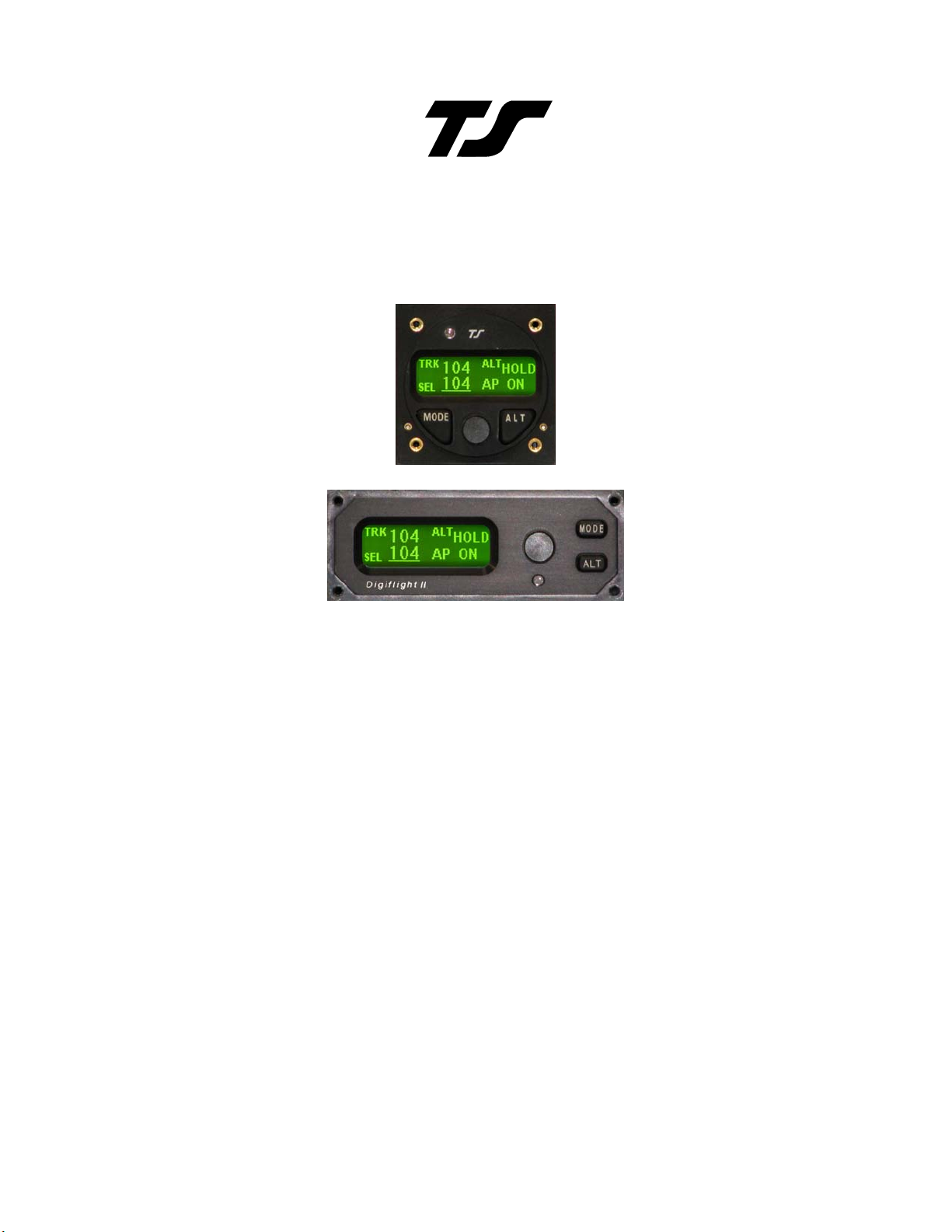
Digiflight II SERIES AUTOPILOTS
TRUTRAK FLIGHT SYSTEMS
1500 S. Old Missouri Road
Springdale, AR 72764
Ph. 479-751-0250 Fax 479-751-3397
Toll Free: 866-TRUTRAK
66-(878-8725)
8
www.TruTrakap.com
Page 2

1
General Information
Introduction...............................................................2
Mode and Data Display.............................................3
Controls.....................................................................4
Initializing the Autopilot...........................................4
GPS Acquisition ....................................................... 5
Digiflight II
Lateral Modes............................................................5
Altitude Hold Mode...................................................6
Minimum and Maximum Airspeed...........................6
Gyro Set.....................................................................6
Power Loss................................................................7
Digiflight IIVS
Lateral Modes............................................................7
Vertical Modes..........................................................8
Setting Pitch Trim .....................................................9
Minimum and Maximum Airspeed...........................9
Gyro Set...................................................................10
Power Loss..............................................................10
Setup Procedure
Digiflight Setup.......................................................10
Table of Contents
Page 3

2
General Introduction
The TruTrak autopilot can be defined as being an orthogonal rate system.
his means that gyroscopic rate sensors are installed so as to sens e motion
T
about each of the major axes (roll, yaw, and pitch). These sensors generate
the fast signal responses necessary to create an autopilot with the best
possible dynamic performance.
To fly an aircraft well about the axis controlled by the ailerons, velocity
of aileron
movement. This means that aileron position corrections do not lag behind
motion of the craft about the roll axis. Aileron control systems that use a
turn coordinator, which senses twice as much azimuth as roll rate, cannot do
this. Instead, yaw disturbances in turbulence cause undesired aileron
movement. In some aircraft this effect is so severe that the controls may
even move momentarily in the wrong direction.
The challenge at TruTrak is to create systems with the very best
dynamic performance available—systems that need not be disengaged in
turbulence, but instead provide function when most needed.
The complete TruTrak flight control system combines all the electronic
and sensing elements needed for the roll and pitch functions and interfaces to
a rate-gyro-controlled yaw damper within a single panel-mounted
programmer/computer package.
Basic directional control is provided by digital selection of a GPS track
to be flown. This replaces heading selection on the DG and e liminates drift
as well as crosswind correction. In the GPS steering mode of operation, th e
system responds to digital guidance information to fly a complex navigation
program.
The vertical portion of the system contains a pressure signal source for
altitude and vertical speed information, an airspeed signal source, and a high
performance pitch rate gyro. These signals are combined to provide
performance equal to that of the most expensive autopilots. Also by having
airspeed information the system is stall proof.
For any set of features, all TruTrak computers are identical. Servos
likewise are identical in velocity response. Servos do differ according to
total torque required. By providing setup functions in the programmer for
system activity and torque, one TruTrak programmer-servo combination can
fly any aircraft.
As a starting point in understanding how to operate the TruTrak syste m,
the following describes the presentation of data, the operating controls, and
the procedures for selecting modes of operation.
movement must be directly proportional to the rate of roll for small
Page 4

3
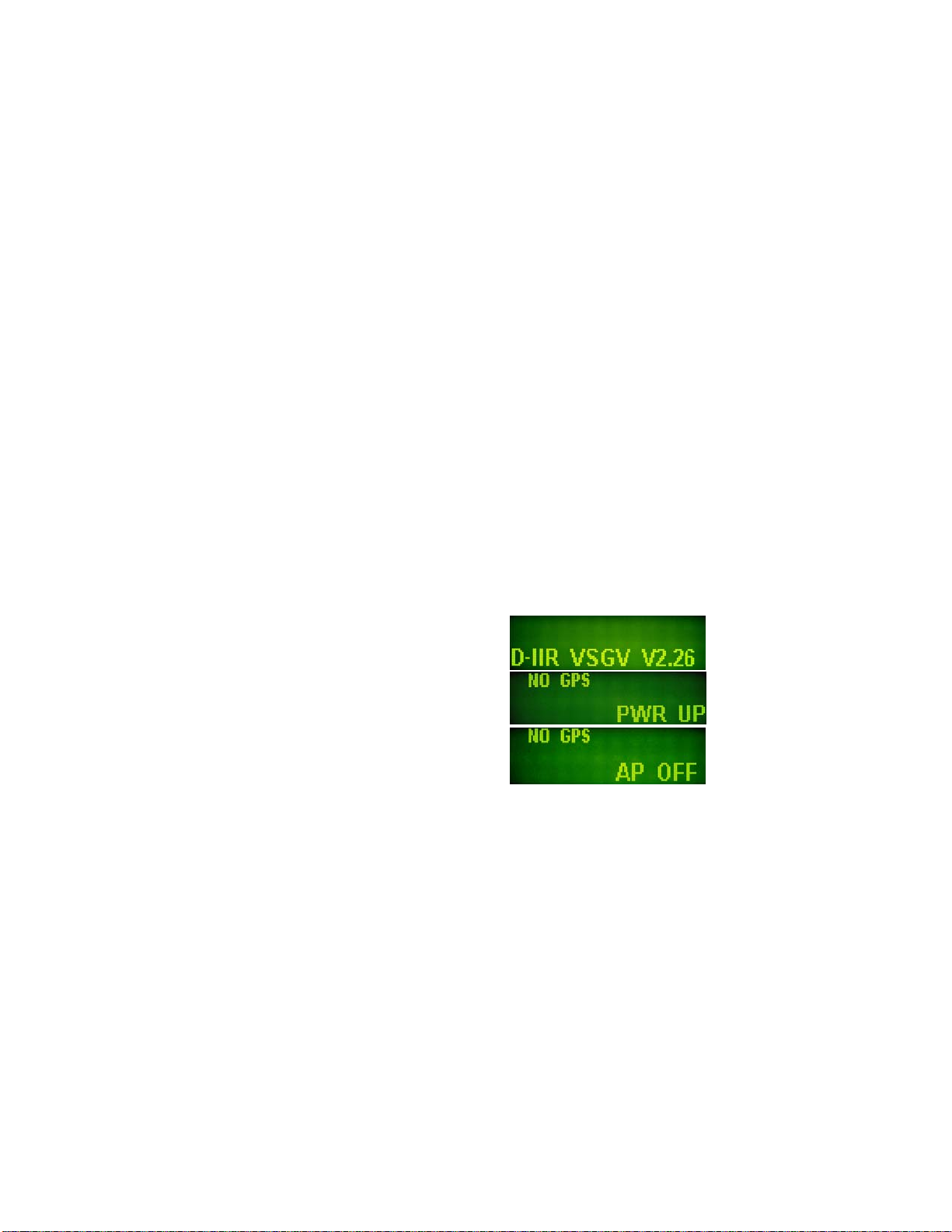
POWER UP—AIRCRAFT STATIONARY
SEE INITIALIZING THE AUTOPILOT PAGE 4
Mode and Data
Display
This display normally
shows operating modes and
associated numerical data. It is
also used to display setup mode
screens and the setting of
associated numerical data.
When displaying operating
modes, the left side shows
lateral data and the right side
shows vertical data. (See figure
below.) The upper left display
labeled TRK shows the
electronic DG slaved to GPS
track. When the GPS track is
not available TRK will be
replaced by BANK, which
means the autopilot now uses
an internal source of gyro
information for bank angle.
The lower left display shows
the selected bank angle of
flight. In the Digiflight II and
IIVS, the upper right shows
whether or not the unit is in the
altitude hold mode. The lower
right display shows selected
vertical speed or whether the
autopilot is on or off.
With the Digiflight IIVS,
the vertical space between the
left and right hand display
area is used to show pitch trim.
This display consists of four
horizontal bars spaced
vertically as the rungs on a
ladder, and are made to move
up or down when the aircraft is
in need of being trimmed.
In the upper left where
direction is shown, a flashing
indicator is present beneath NO
. When there is GPS serial
FIX
data present but no position fix,
this will be a flashing period.
Once GPS position data
becomes valid this will be a
flashing asterisk and GPS OK.
If GPS flight plan information
is being received over the serial
channel or if the programmer is
a Digiflight IIVSG and GPS
steering information is being
received, a flashing plus sign
will indicate the presence of a
useable steering (
GPSS mode)
or waypoint to waypoint (GPS
NAV mode) signal.
A cursor in the form of an
underline is shown beneath the
SEL numerals. This is used to
indicate that an underlined
number can be set by rotation of
the encoder knob.
DG SLAVED
→
TO TRACK
SELECTED
→ ←
DIRECTION
TRIM INDICATOR
↑
SELECTED
VERTICAL SPEED
Page 5
Controls
The Digiflight II series
autopilot uses the simplest
controls available. All
programming is done via a
rotary encoder knob and two
buttons labeled MODE and
ALT. The MODE button
toggles between the default
(TRK) mode and the
mode (or GPS
GPS steering is not available),
as well as moves the cursor
back to the SEL numerals. The
ALT button engages altitude
hold or moves the cursor to the
SVS numerals. If in the
mode, the ALT button will
engage the
available. Both buttons are also
used to enter the setup modes as
well as maneuver through the
setup screens. Engaging the
autopilot can be done either by
momentarily pushing and
releasing the encoder knob on
the programmer or by pushing
and holding the switch located
on the control wheel or stick for
more than two seconds and then
releasing. Disengaging can be
done either of two ways: by
pushing and holding the
encoder knob on the
programmer for approximately
three seconds and then releasing
the knob, OR by momentarily
pushing and releasing the
switch located on the control
wheel or stick. This means that
in addition to disengaging the
autopilot, this switch also
provides the function referred to
NAV mode if
GPSV mode, if it is
GPSS
GPSS
4
as Control Wheel Steering in
that the autopilot synchronizes
to both direction and vertical
speed upon being engaged.
Initializing the
Autopilot
The autop ilot master switch
should be in the off position
when the engine is started.
Aircraft electrical systems can
generate voltage transients
during an engine start, and like
other avionics systems, the
autopilot should not be
subjected unnecessarily to these
conditions. After start up, turn
on the autopilot master switch
and hold the aircraft stationary
as the internal gyros are
initialized. The model and
software version will be
displayed for approximately ten
seconds in the lower left. Then
PWR UP in the lower right
takes approximately another ten
seconds.
When initializing is complete
PWR UP will change to AP
OFF
Page 6

5
GPS Acquisition
Beneath the word NO FIX a
flashing period
• will appear
each time the GPS sends a
message to the autopilot (once
per second). This indicates the
GPS is working but has not yet
obtained a position fix. As long
as the period is shown, the NO
FIX display cannot transition to
the TRK mode.
Digiflight II
Lateral Modes
Upon being engaged, the
autopilot will be in the basic
lateral track mode, and it will
be synchronized to the direction
being flown at the time. The
number following SEL
(Selected direction) is
underlined, meaning that
rotation of the encoder will
select heading. Rotation of the
knob when it is not depressed
will cause 5° steps of SEL and
when it is depressed the steps
will be 1°.
If a GPS flight plan has
been entered into the GPS,
pushing MODE will engage the
GPS
plus sign will show. In the GPS
NAV mode, the autopilot will
follow a flight plan
NAV mode and a flashing
When the GPS does obtain
a fix, the period will be
replaced by an asterisk *. This
means that when a certain
velocity is attained
GPS OK will
be replaced by TRK. This
happens at approximately 10
Knots ground speed as detected
by GPS and will even occur at
rapid taxi speeds.
If the GPS has a flight plan
entered there will be a + after
position fix is established.
programmed into the GPS.
However, the autopilot must
over-fly each way point prior to
turning and intercepting the
next course line.
If the GPSS option has
been added, pushing the MODE
button will engage GPS
steering. In the
GPSS mode the
autopilot follows lateral
steering or bank commands
generated by a navigation
system (EFIS or GPS).
Page 7

Altitude Hold Mode
When the autopilot is
engaged it will be in the basic
lateral track mode, and will
synchronize to the direction
being flown at the time. The
pitch servo will not be engaged
at this time. To engage the
altitude hold the aircraft must
be at the desired altitude and be
trimmed for level flight. After
trimming the aircraft, to enter
the altitude hold mode, simply
press and release the ALT
button. The display will show:
6
minimum airspeed set in the
autopilot, the autopilot will
allow the aircraft to begin a
descent and flash
the display.
Likewise if the autopilot is in
altitude hold and the pilot adds
power to a point at which the
airspeed reaches the maximum
airspeed, the autopilot will
allow the aircraft to climb and
will flash
display.
MAX AS on the
MIN AS on
If an altitude change is
desired, it is necessary to turn
off the altitude hold. To do
this, press and release the ALT
button. The display will show:
Minimum and
Maximum Airspeed
The Digiflight II series
autopilots have a minimum and
maximum airspeed feature.
These are added only for safety.
If the autopilot is in altitude
hold and the pilot reduces
power to a point at which the
airspeed falls below the
Gyro Set
When the initializing has
been done correctly, the gyros
should already be centered at
the time of take off. If
confirmation of this is desired,
with the aircraft stationary on
the runway and the autopilot
disengaged, pressing and
holding the encoder knob will
put the gyros in the fast
centering mode. The knob
should be depressed for
approximately 3 seconds during
which time the words
SET
will be displayed.
GYRO
Page 8

Continue depressing the knob
for 15 seconds to set the gyro
center.
Power Loss
If there is a momentary
loss of electrical power, the
autopilot will disengage. The
autopilot gyros may need to be
manually re-initialized using
GYRO SET operation.
the
7
Manually fly the aircraft in a
straight line as steadily as
possible, while holding in the
knob for at least ten seconds
after the words
appear in the display. After
approximately ten seconds have
elapsed, release the knob. The
autopilot may now be reengaged, and any residual gyro
offset will be slaved away
automatically.
GYRO SET
Digiflight IIVS
Lateral Modes
Upon being engaged, the
autopilot will be in the basic
lateral mode, and it will
synchronize to both the
direction and vertical speed
being flown at the time. The
number following SEL
(Selected direction) is
underlined, meaning that
rotation of the encoder will
select heading. Rotation of the
knob when it is not depressed
will cause 5° steps of
when it is depressed the steps
will be 1°.
If a GPS flight plan has
been entered into the GPS,
pushing the MODE button will
engage the GPS
SEL and
NAV mode and
a flashing plus sign will show.
In the GPS
autopilot will follow a flight
plan programmed into the GPS.
However, the autopilot must
over-fly each waypoint prior to
turning and intercepting the
next course line.
If the GPSS option has
been added, pushing the MODE
button will engage the GPS
Steering. In the
the autopilot follows lateral
steering or bank commands
generated by a navigation
system (EFIS or GPS). Once in
GPSS mode, pushing the
the
ALT button will enter the
NAV mode the
GPSS mode
GPSV mode as well. This
feature will only be available
when coupled to certain EFIS
Page 9

systems or a GPS with vertical
GPS steering outputs.
Vertical Modes
When the autopilot is
engaged it will synchronize to
the direction and vertical speed
being flown at the time, the
lower right section of the
display shows SVS (selected
vertical speed). To enter
altitude hold at any time, push
and release the ALT button two
times.
If an altitude change is
desired, momentarily push and
release the ALT button and the
cursor will move over to the
selected vertical speed.
Rotation of the encoder
knob will now change the
selected vertical speed.
If the cursor is under the SVS
number a single click of the
8
ALT button will select zero
vertical speed. If the selected
vertical speed is set to zero, the
display will show:
Once the desired vertical
speed has been selected,
momentarily pushing and
releasing the MODE button will
move the cursor back to
after approximately seven
seconds without moving the
encoder, the cursor will move
back to SEL
If the autopilot is coupled to a
GPS or EFIS system which can
provide vertical GPS steering,
once in the GPSS mode,
pushing the ALT button will
enter the GPSV mode as well.
To use the GPSV mode with the
GNS 430/530/480, the aircraft
must be below the virtual glide
slope and the autopilot must be
in altitude hold. When
approach is initiated and the
CDI becomes active, the GPSV
button can then be pushed and
the unit will enter the GPSV
mode. The first screen will
show as below:
The screen will oscillate
between GPSV FLG and GPSS
HLD. When the VDI is no
longer flagged, the unit will
.
SEL, or
Page 10

enter GPSV hold, and the
display will show as below:
Once the VDI has been above
the center by one dot for at least
5 seconds the GPSV mode will
ARM, and the display will
show:
As the VDI passes through
center, the autopilot will couple
to the virtual glide slope, and
the display will show that the
autopilot is now coupled to the
virtual glide slope as below:
Missed approach
Once the Glide Slope is coupled
press any button to activate the
Go Around mode. The
autopilot will pitch up to +500
fpm and will engage TRK mode
on the current track.
Setting Pitch Trim
The pitch servo contains a
torque sensor that sends a signal
to the computer wh en the up or
down force greater than a
threshold value is required to
fly a selected flight condition.
When this signal indicates an
9
out of trim condition that
persists in one direction for
more than a pre-set length of
time, the three moving
horizontal bars will come into
view and move according to the
direction in which trim is
required. The pilot is then
required to operate the trim
control (electric or manual) so
as to bring the system to neutral
trim. With mechanical trim this
is easily done, but with electric
systems it may be necessary to
develop a technique. If the trim
is slow enough, the pilot has
plenty of time to react when the
bars disappear before the trim
condition is reversed. With a
fast trim it will be necessary to
tap or pulse the trim button so
that it will be slow enough to
turn it off before going too far.
When a reversal takes place, a
slight tap in the opposite
direction may be required to get
the bars to stay off. Finally
when the bars have been made
to disappear and there has been
no speed change, the bars can
be ignored if they reappear in
that it is known the aircraft is
close to being in trim.
Minimum and
Maximum Airspeed
The Digiflight II series
autopilots have a minimum and
maximum airspeed feature.
These are added only for safety.
This feature is easier described
using the Digiflight IIVS model
as an example. If the pilot
Page 11

commands a vertical speed
climb in which the aircraft
slows to the minimum airspeed,
the aircraft will maintain that
airspeed and will flash
on the display.
Likewise if the pilot commands
a vertical speed descent in
which the aircraft accelerates to
the maximum airspeed, the
autopilot will not fly the
selected vertical speed, but will
maintain the maximum airspeed
and flash
MAX AS.
MIN AS
Gyro Set
When the initializing has
been done correctly, the gyros
should already be centered at
the time of take off. If
confirmation of this is desired,
with the aircraft stationary on
10
the runway and the autopilot
disengaged, pressing and
holding the encoder knob will
put the gyros in the fast
centering mode. The knob
should be depressed for
approximately 15 seconds
during which time the words
GYRO SET will be displayed.
Power Loss
If there is a momentary
loss of electrical power, the
autopilot will disengage and
repower up. The autopilot gyros
may need to be manually re-
initialized using the
operation. Manually fly the
aircraft in a straight line as
steadily as possible, while
holding in the knob for at least
ten seconds after the words
GYRO SET appear in the
display. Continue to hold for
approximately ten seconds,
release the knob. The autopilot
may now be re-engaged, and
any residual gyro offset will be
slaved away automatically.
GYRO SET
Page 12

11
Digiflight Setup Procedure
The setup consists of
setting activity, torque, serial
baud rate, bank angle setting,
micro activity, minimum
airspeed, maximum airspeed
and static lag. To enter the
lateral setup mode, press and
hold the MODE button for
approximately 3 seconds, until
the first setup screen appears.
The first setup screen shows the
current value for the activity of
the aileron servo, with an
underline under the present
setting of activity. A typical
screen might show:
The underlined number is
set by rotating the encoder
knob. Turn this knob to set the
activity level to the desired
value for the particular aircraft.
Any value between 0 and 36
may be chosen. In this example,
the value of 3 will be selected.
Activity should be set so as to
not be excessive in turbulence
and yet sufficient to fly without
hunting in still air. (Any lost
motion or play between the
servo and the control surface
can cause hunting in still air).
Once activity is set to the
desired value, press and release
the ALT button to advance to
the next setup screen.
In a manner similar to
activity, use the encoder knob to
select the desired value of roll
servo torque. This value should
be between 7 and 12. A default
value is set at the factory but
may need to be modified to suit
a particular aircraft. The value
chosen should be sufficient to
fly the aircraft, but not so much
that it is difficult to override the
autopilot if necessary.
Having selected the desired
torque level, again press and
release the ALT button to
advance to the next setup
screen. The unit will now show
the next screen:
The value shown represents
the speed of the primary RS232 interface to the external
GPS unit. By default at the
factory it is set to 9600 baud.
However, it may be set to any
of 600, 1200, 2400, 4800, or
9600 baud. Consult the manual
for the GPS unit and follow its
setup instructions to determine
its setting and set the baud rate
of the autopilot to the same
value. The autopilot will
recognize NMEA-0183 protocol
Page 13

or Garmin protocol (moving
map output).
Once the desired baud rate
or Garmin protocol has been
selected, again press and release
the ALT button to advance to
the next setup screen. The unit
will now show the next screen:
The bank angle setting can
be adjusted to suit the pilot.
This setting controls how much
bank the autopilot will
command when in a turn. This
will not change the flight
dynamics of the system and any
of the three settings will fly the
aircraft equally well. Once the
desired bank angle setting is
selected, press and release the
ALT button to advance to the
next setup screen. The unit will
now show the next screen:
The micro activity setting
in most aircraft will be left at
zero (0). Micro activity is used
only in aircraft in which a slow
wing rock has been observed in
very still air. Sometimes there
will be a small amount of lost
motion in an aircrafts control
system, and the micro activity
setting is a way to compensate
for the lost motion. Press and
release the ALT button to
advance to the next setup
12
screen. The unit will now show
the next screen:
This setup screen is used to
increase the bank angle that the
autopilot will fly in GPS
Steering mode. Increase the
value to increase the allowable
bank angle. Press and release
the ALT button to advance to
the next setup screen, which is
shown below:
Set the Yaw Damper? to Y if
there is a yaw damper installed
and N if there is not a yaw
damper installed. Press and
release the ALT button to
advance to the final setup
screen.
This concludes the lateral
setup procedure.
Page 14

To configure the pitch portion
of the autopilot push and hold
the ALT button for 3 seconds.
The first setup screen allows the
pitch axis to be turned on or off.
(NOT USED IN DII) The
default of on will always be
selected after a power cycle.
To turn the pitch axis off,
select off, and click the knob to
exit. To advance to the next
setup screen, press and release
the ALT button, the next setup
screen is shown below:
Turn the encoder knob to
set the activity level to the
desired value for the particular
aircraft. Any value between 0
and 24 may be chosen. In this
example, the value of 3 will be
selected.
Once activity is set to the
desired value, press and release
the ALT button to advance to
the next setup screen:
In a manner similar to
activity, use the encoder knob to
select the desired value of pitch
servo torque. This value should
be between 7 and 12. A default
13
value is set at the factory but
may need to be modified to suit
a particular aircraft. The value
chosen should be sufficient to
fly the aircraft, but not so much
that it is difficult to override the
autopilot if necessary.
Having selected the desired
torque level, again press and
release the ALT button to
advance to the next setup
screen. The next screen will
show:
Use the encoder knob to
select the minimum airspeed at
which the autopilot will fly the
aircraft. This speed should be a
safe margin above a stall. Press
the ALT button to advance to
the next setup screen. The next
screen will show:
The maximum
airspeed value is the fastest
indicated airspeed the autopilot
will fly, independent of what it
is commanded to do. Rotate the
knob to adjust this airspeed to a
value safely below the red line
airspeed, but above the normal
cruise speed. Select the desired
value, and then press the ALT
button to advance to the next
setup screen.
Page 15

The next screen in the setup
procedure is the static lag setup
screen. This setting should only
be changed if autopilot tends to
oscillate in pitch during altitude
hold, due to lag in the static
system. The display will show:
Rotating the encoder knob
will change the number as in
previous setup screens. Having
selected the desired value, press
the ALT button to advance to
the next setup screen. The next
screen will show:
As before in the lateral
setup mode, the micro activity
setting in most aircraft will be
left at zero (0). Micro activity
is used only in aircraft in which
a slow oscillation has been
observed while in altitude hold,
in very still air. Sometimes
there will be a small amount of
lost motion in an aircrafts
control system, and the micro
activity setting is a way to
compensate for the lost motion.
Press and release the ALT
button to advance to the final
setup screen.
14
This setting in most cases
will not need to be changed. If
the half step setting is set to Y
(yes), then the pitch servo will
now have higher resolution, and
take smaller steps. While this
setting will make the servo take
smaller steps, it will decrease
the amount of available torque.
This setting should be left at N
(No), unless it is observed that
the nose moves up and down
very slightly while in altitude
hold in very still air. Press and
release the knob and the display
will return to normal flight
screen.
Contrast Adjustment
The Digiflight II contrast
should only be adjusted while
on the ground. To enter the
contrast adjust mode, with the
autopilot powered off, push and
hold the encoder knob in. Turn
on the power to the autopilot,
and after 1 second release the
knob. The display will show
the current contrast setting.
Rotate the knob to select
the desired contrast ratio.
Repeat for MIN light setting.
Too low a number and the
words will fade out on the
display, and too high a number
the background will become
dark, and the text unreadable.
To exit, press and release the
encoder knob.
Page 16

TruTrak Flight Systems, Inc.
(11/09)
Printed in U.S.A.
 Loading...