

Page 1
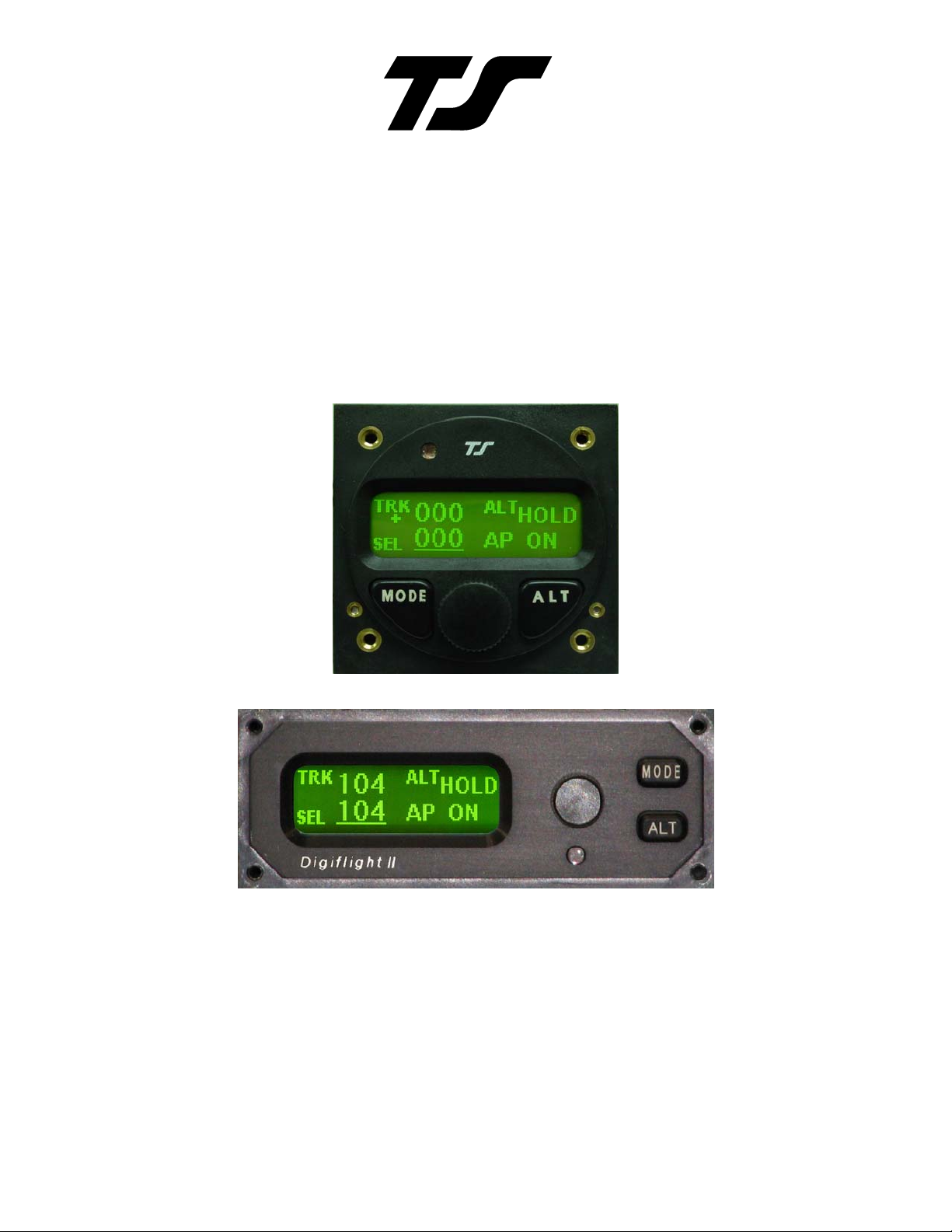
DigiFlight II Series Autopilots
Installation Manual
8300-008 Rev D
TRUTRAK FLIGHT SYSTEMS
1500 S. Old Missouri Road
Springdale, AR 72764
Ph: 479-751-0250 Fax: 479-751-3397
www.trutrakap.com
Page 2

INSTALLATION MANUAL
For
DigiFlight II Series Autopilots
TABLE OF CONTENTS
Mechanical Considerations........................................................................................................................................... 1
Pitot / Static Connections..............................................................................................................................................2
RFI / EMI Considerations............................................................................................................................................. 2
DigiFlight II Series Ground Checkout..........................................................................................................................3
DigiFlight II Series First Flight ....................................................................................................................................6
GPSS / GPSV APPROACH PICTORIAL ...................................................................................................................8
Electrical Pin-out .......................................................................................................................................................... 9
DigiFlight II Wiring Diagram..................................................................................................................................... 10
DigiFlight II Series Block Diagram............................................................................................................................11
DigiFlight II Series with Pitch Trim Block Diagram..................................................................................................11
DigiFlight II Series with Yaw Damper Option Block Diagram .................................................................................12
GPS Setup Guide ........................................................................................................................................................13
Garmin 430W and 530W ......................................................................................................................................................... 15
Magnetic Considerations Supplement ........................................................................................................................ 17
Definitions ..................................................................................................................................................................19
RETURN MERCHANDISE POLICY AND PROCEDURE................................................................................ 21
Revision Date Description Page #
A 07/01/2008 Initial Release
B 05/20/2009 Removed Magnetic backup 2, 6, 8
C 06/16/2009 Update pictures added Magnetic supplement 3,4, 18
D 12/07/2009 Updated Warranty information 20
Page 3
Mechanical Considerations
The installation information in this section is extremely important and must be clearly
understood by the installer. Improper servo installation or failure to observe and diagnose
installation problems prior to flight can result in extremely serious consequences, including
loss of ability to control the aircraft. If there are any questions on the part of the installer it
is mandatory to resolve these questions prior to flight of the aircraft.
Most modern experimental aircraft use push-pull tubes to drive the primary controls. These tubes generally have a total travel
of 3” or less; therefore, it is best to connect the autopilot servo to the primary control by the same method. This connection
consists of an arm on the servo connected by a push-pull rod to the primary control. Rod-end bearings are required on each
end of the push-pull rod.
The servo arm must not rotate even near to the point called OVER CENTER, the point at which the primary
aircraft control would lock up. Some aircrafts mechanical primary control installations will not allow this to
occur and do not need the servo stops.
This is a condition that would result from the servo being back driven when the pilot operates the controls, or
from the servo itself driving the controls to a stop. To protect against this mechanical stops are supplied with the
servos. These stops are drilled so that they can be mounted at different angles as required (18° intervals).
In addition to the proper use of the stop it is important to know the amount of travel on the primary control that
the servo can handle. With the push rod connected to the outermost hole (1 ½”) the travel on the primary cannot
exceed 2 ½”, the intermediate hole 2 1/16”, and the inner hole 1 5/8”.
It is important to note that at the neutral point of the control the SERVO ARM must be PERPENDICULAR to the
push rod, and that the stop must be mounted so as to limit travel as near as possible to equal amounts in both
directions. In certain factory-designed installations there may be well-proven exceptions.
There will be installations in which space does not permit the use of the stop. When this is done the aircraft’s primary control
stops must be positive and care must be taken to be sure that at the neutral point the servo arm is perpendicular to the push rod,
and that the travel limits of the servo arm are not exceeded.
There are installations in which the travel of the push-pull tube exceeds the allowable 2 ½”. For such installations, the drive
can be applied to a bell crank at a radius point that moves the desired 2 ½” of maximum allowed travel in the outermost hole of
the arm.
When there is no way to have a drive point of less than 2 ½” or when the primary control is cable-driven it is necessary to use
the capstan-cable servo drive. When this is done the servo should be mounted so that the 1/16” diameter cable which wraps
around the capstan when extended parallel to the primary cable is approximately 3/16” from the primary cable. If the primary
control travel does not exceed 5” the cable locking pin will be 180° away from the point at which the cable leaves the capstan.
When the primary control is at the neutral point this means the total cable wrap around the capstan is 360°. If the primary
control travel is greater than 5” the cable wrap is 720°and the pin is adjacent to the output point when the primary control is at
the neutral point.
The cable clamps when properly installed will not slip and thus get loose, but it is desirable to NICO press or swedge a fitting
on to the cable so as to provide added assurance that the cable will not become slack. If the bridle cable is not sufficiently tight
there will be lost motion in the autopilot drive. This will result in hunting (oscillation).
TruTrak Flight System 1 DigiFlight II Series Auto Pilot Installation Manual
December 2009 8300-008 Rev D
Page 4

PROGRAMMER INSTALLATION
Mounting Considerations
The DII programmer unit is designed to mount in the aircraft instrument panel within view and reach of the pilot. Maximum
recommended viewing angle should be no more than 20 deg
degrees longitudinal axis and 0 degrees lateral axis. The primary unit location should minimize pilot head movement when
transitioning between looking outside of the cockpit and viewing/operating the programmer unit. The location should be such
that the programmer unit is not blocked by the glare shield on top, or by the throttles, control yoke, etc. on the bottom. Use
aircraft installation standards for mounting and support of the programmer.
. The maximum mounting angle the DII can accommodate is 12
Wiring Considerations
Use AWG #24 or larger wire for all connections unless otherwise specified. The standard solder pin contacts supplied in the
connector kit are compatible with up to AWG #18 wire. In cases where some installations have more than one component
sharing a common circuit breaker, sizing and wire gauge is based on, length of wiring and current draw on units. In these cases,
a larger gauge wire such as AWG #20 may be needed for power connections. Do not attach any wires to the outside of the
programmer or route high current wires within six (6) inch of the programmer. Ensure that routing of the wiring is not exposed
to sources of heat, RF or EMI interference. Check that there is ample space for the cabling and mating connectors. Avoid
sharp bends in cabling and routing near aircraft control cables. Do not route the COM antenna coax near any autopilot
components.
Pitot and Static Connections
All multi-servo TruTrak autopilots require connections to the pitot and static lines. The preferred method of this connection
would be tee fittings near the aircraft’s altimeter. The static line for the autopilot requires due care in its construction, as
excessive lag or insufficient static orifices can cause the autopilot to oscillate (hunt) in pitch. Although there is compensation
within the autopilot sufficient to handle moderate amounts of lag, the importance of a good static port and line cannot be
overstated. In some cases problems can be caused by having a large number of devices (including the autopilot) connected to a
single, insufficient, static port. In other cases, the static line itself is adequate but there are one or more devices connected to the
same line, one of which has a large static reservoir. A simple remedy for this problem if it occurs is a tee-fitting near the static
port, and a dedicated line to the autopilot only. Obviously, an insufficiently-large orifice coupled with large static reservoirs
can aggravate the problems associated with lag.
RFI/EMI considerations
The autopilot programmer is shielded and does not generate any appreciable level of electromagnetic interference. Moreover,
the servo lines (except for power and ground) are low-current and cannot contribute to RF interference. The servo power and
ground lines do have switching currents through them, but so long as there are no parallel runs of servo power and ground lines
with such things as poorly-shielded antenna lines or strobe light power lines, there is no need to shield the servo harnesses.
The autopilot itself has been internally protected from RF interference and has been tested under fairly extreme conditions,
such as close proximity to transmitting antennas. However, it is always good practice to insure that such antennas are properly
shielded and not routed directly over or under sensitive panel-mounted electronic equipment. Most problems in this area are the
result of improper RF shielding on transmitting antennas, microphone cables, and the like. The most sensitive input to the
autopilot is the Control Wheel Switch input. This line should not be routed in parallel with transmitting antennas or other
sources of known RF interference. If necessary, it can be shielded with the shield connection to pin 13 of the autopilot
connector.
TruTrak Flight System 2 DigiFlight II Series Auto Pilot Installation Manual
December 2009 8300-008 Rev D
Page 5
DigiFlight II Series Ground Checkout
Must be performed before first flight
Once wiring is completed the autopilot should be tested in the aircraft while on the
ground. The first step is to enter the setup mode on the autopilot and set all parameters to
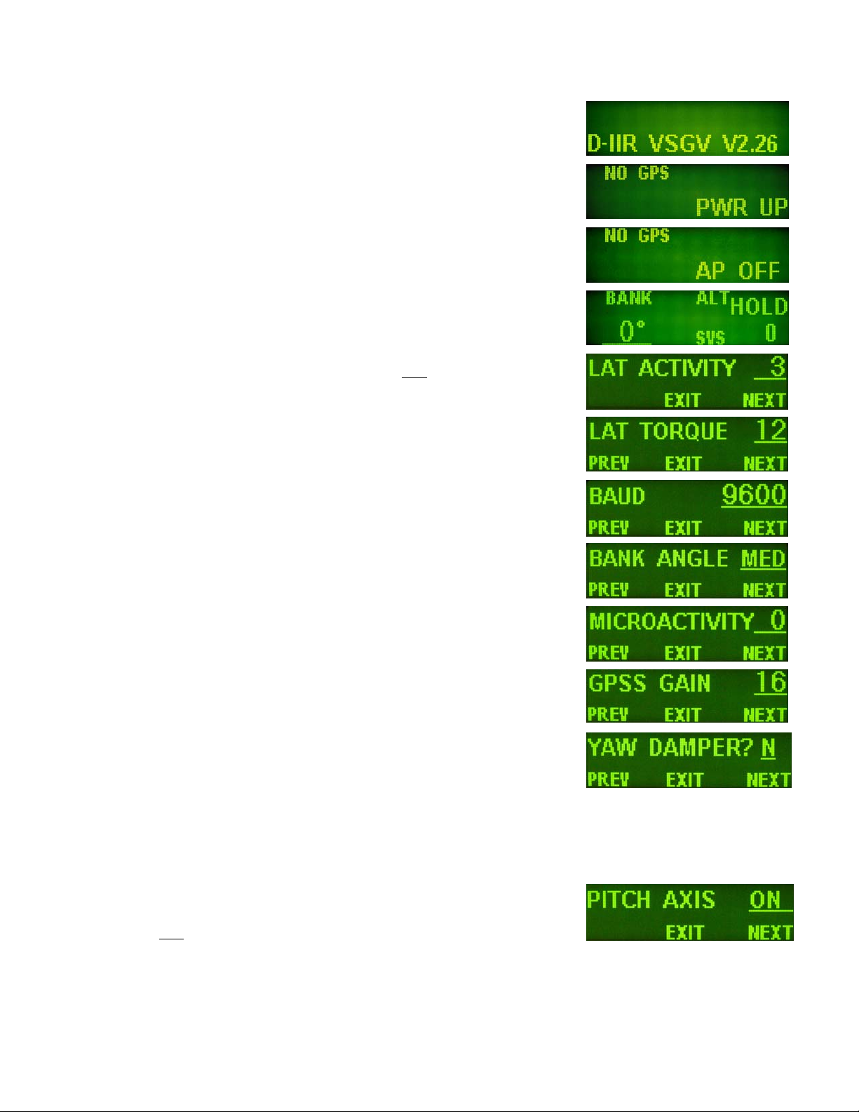
their correct values. Apply power to the autopilot programmer.
The initial screen should be displayed, along with the words PWR UP in the lower-right
of the display. After approximately ten seconds, the autopilot is ready to be set up for
operation, indicating AP OFF on the display.
Many of the operations of the autopilot are initiated or confirmed by a press and release
of the knob (without rotating it). This is referred to as the ENTER operation.
Disengaging of the autopilot is done by holding the knob in for an extended period of
time. Any time there is an underlined field showing on the autopilot screen, rotating the
knob will cause the underlined active field to change.
Engage the autopilot by pressing ENTER. Then press and hold the MODE button in for
about three seconds until the first setup screen, showing LAT ACTIVITY is displayed.
Once the activity setup screen is on the display, rotate the knob as necessary to set the
lateral activity value to a value of 2 or 8 if High Torque servo. Push the ALT button to
move to the next setup screen.
The next setup screen is LAT TORQUE. Insure that the value displayed is somewhere
close to the maximum value of 12. Once that is done, press the ALT button to advance
to the next setup screen.
Rotating the knob, select a value for BAUD which is compatible with the GPS receiver
connected to pin 17. The value of 9600 is the most commonly used rate. Once baud rate
selection is done, press the ALT button to advance to the next setup screen.
The next setup screen is the BANK ANGLE screen. Select an initial setting of MED.
Once this is done, press the ALT button to advance to the next setup screen.
The next setup screen is the MICRO ACTIVITY screen. This setting should be set
initially to a setting of 0. Once the micro activity is set to 0, press the ALT button to
advance to the final lateral setup screen.
The next setup screen is the GPS GAIN screen. This setup is used to increase the bank
angle that the autopilot will fly in GPS Steering mode. Increase the value to increase the
allowable bank angle. Press the ALT button to advance to the next setup screen.
The next setup screen is the YAW DAMPER screen. Set to Y if a yaw damper is
installed, otherwise, select N and Press the ALT button to advance to the next setup
screen.
Press the knob to exit, and return to the main flight screen.
Then press and hold
screen, showing PITCH AXIS is displayed. (NOT USED IN DII) The default of ON
will always be selected after a power cycle. To turn the pitch axis off, select OFF, and
click the knob to exit. To advance to the next setup screen, press the ALT button to
advance to the next setup screen.
TruTrak Flight System 3 DigiFlight II Series Auto Pilot Installation Manual
December 2009 8300-008 Rev D
the ALT button in for about three seconds until the first setup
Page 6
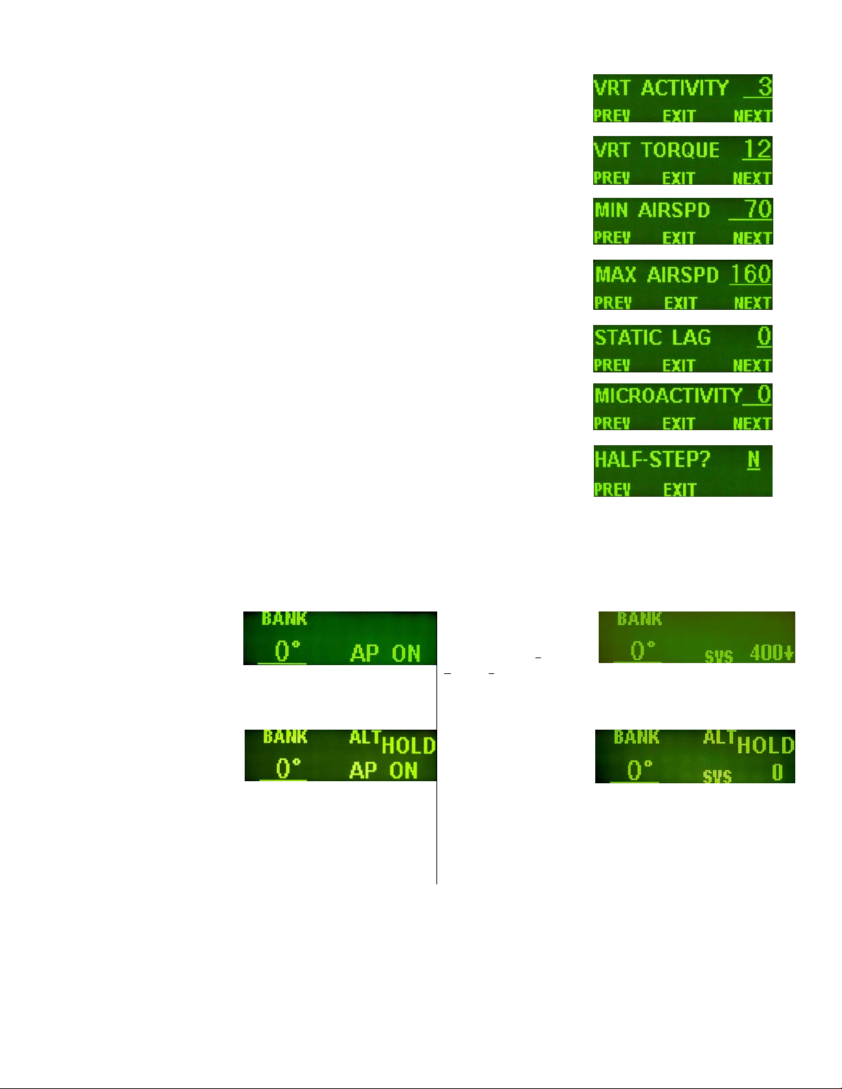
The VRT ACTIVITY is displayed. Rotate the knob as necessary to set the vertical activity
value to a value of 2. Push the ALT button to move to the next setup screen.
The next setup screen is VRT TORQUE. Insure that the value displayed is set to the
maximum value of 12. Once that is done, press the ALT button to advance to the next setup
screen.
The next screen allows a MIN AIRSPD to be set. The minimum airspeed value is the
slowest indicated airspeed the autopilot will fly, independent of what it is commanded to do.
Rotate the knob to adjust this airspeed to a value safely above a stall but lower than normal
approach or climb out speeds. Select the desired value, and then press the ALT button to
advance to the next setup screen.
The next screen allows a MAX AIRSPD to be set. The maximum airspeed value is the
fastest indicated airspeed the autopilot will fly, independent of what it is commanded to do.
Rotate the knob to adjust this airspeed to a value safely below the red line airspeed, but
above the normal cruise speed. Select the desired value, and then press the ALT button to
advance to the next setup screen.
The next screen allows an adjustment for the amount of delay, or “lag” in the aircraft static
system. Start with a value of zero (0) until the first flight test of the autopilot. Having
verified this selection and set it to zero, press the ALT button to advance to the next setup
screen.
The next setup screen is MICRO ACTIVITY for the pitch axis, as with the lateral micro
activity this setting should be set initially to a setting of 0. Once the micro activity is set to
0, press the ALT button to advance to the final setup screen.
The final setup screen is the HALF-STEP setup screen. This screen is to change the
resolution of the pitch servo. Initially this setting should be set to N (No). Once this is
done, press the knob to exit and return to the main flight screen.
The next step in the check-out procedure is to verify that the servos run, and in the correct direction. At this point, the display
differs depending on autopilot model.
DigiFlight II DigiFlight IIVS
The screen will show that the
altitude portion of the
autopilot is still disengaged.
Press the ALT button to
engage the altitude hold
function.
Ø
In both cases, the selected heading will be underlined on the bottom left of the display, and the autopilot will be in the altitude
hold mode. Both the pitch and roll servos should stop, or move only very slowly.
The lower right of the
screen will show the
present value of s
ertical speed, (SVS)
v
which will be
approximately zero. If it
is not zero, press the
ALT button to move the
cursor to the SVS field,
and then use the knob to
set the value to 0. The
display will change to
show altitude hold
mode.
elected
Ø
TruTrak Flight System 4 DigiFlight II Series Auto Pilot Installation Manual
December 2009 8300-008 Rev D
Page 7

DigiFlight II DigiFlight IIVS
The autopilot programmer unit needs to be out of the panel, so
that it can be gently
and nose-down flight. If the autopilot is tipped in a nose-down
maneuver, the control should move in such a way as to
attempt to move the control yoke or stick back, in an effort to
raise the nose of the aircraft. Similarly, a nose-up tipping of
the autopilot should push the yoke or stick forward in an
effort to lower the nose of the aircraft.
Using the ALT button will toggle the altitude hold on and off.
When the altitude hold is off, the pitch servo is electrically
disconnected and will not move in response to disturbances.
If the direction of movement of the pitch servo is incorrect, install or remove the jumper between pins 1 and 2 of the autopilot
connector and repeat the setup to verify correct results up to this point.
The roll servo should also be responding at this time, moving the controls in such a way as to turn the aircraft from the current
heading (shown as a 3-digit number after the word HDG in the upper-left of the display) to the selected
digit number after the word SEL in the lower left of the display). The initial value of the selected heading is the current heading
of the aircraft at the moment of engagement, but the knob can be used to modify the selected heading. When the heading
shown as SEL agrees with the heading of the aircraft shown in the top line as HDG, the roll servo should stop or run only very
slowly. If the knob is rotated clockwise, to a selected heading right
move in such a way as to roll the aircraft to the right. Conversely, a selected heading to the left
move the controls in the opposite direction to attempt a roll towards the left. If servo direction is not correct, the wires going to
pins 4 and 5 of the roll servo (pins 20 and 21 on the main connector) must be reversed to achieve the correct response. If a
servo does not move at all, double-check the LAT TORQUE or VRT TORQUE setting as appropriate. If a servo jitters but
does not actually rotate, check the wiring on the four servo drive lines to that servo for continuity and correctness. If the servo
does not seem to have any torque, check the relevant torque control line for continuity and correctness.
tipped fore-and aft to simulate nose-up
With the cursor in the SVS field, rotate the knob clockwise
until several hundred feet per minute is showing in the field.
At this point, the pitch servo should be moving the control
yoke or stick back, in an effort to raise the nose of the aircraft.
Similarly, rotating the knob counter-clockwise to select a
negative vertical speed (descent) the pitch servo should be
moving the controls in such a way as to lower the nose of the
aircraft.
Using MODE and ALT buttons will toggle the cursor back
and forth between the SVS field and the SEL (selected
heading) field. The cursor will revert back to the selected
heading field after a few seconds of inactivity.
heading (shown as a 3-
of the current heading, the control yoke or stick should
of the current heading will
At this time, check that each servo arm or capstan is properly operating the controls. For servo installations using an arm, check
that as the controls go from limit to limit the arm of the servo remains in the operating range of the servo (a maximum of 100
degrees total rotation) and that when the controls are centered, the connecting pushrod is approximately perpendicular to the
arm of the servo. For capstan systems, insure that the cabling remains at proper tension and is properly secured as the servo
moves the controls from stop to stop. Insure that each servo remains secure in its mounting and does not flex its mounting
bracket as it drives the control to its stops. For installations using an arm, insure that as the servo moves the control towards the
end of control travel it does not cause the main control’s torque tube or push-pull tube to flex in any way that could cause
control system lockup at the extremes of servo travel. Insure that any “lost motion” in the linkages is eliminated or minimized,
in order to maximize the performance of the autopilot. Lost motion (dead zone) will result in wandering or slow “hunting”
behavior in flight.
Summary:
ENGAGE AUTOPILOT WITH FLIGHT CONTROL CENTERED,
ROTATE KNOB CLOCKWISE. FLIGHT CONTROL MUST MOVE
TOWARD RIGHT. ROTATE KNOB COUNTER CLOCKWISE,
FLIGHT CONTROL MUST MOVE BACK TOWARD LEFT.
DII VS: TAP “ALT” BUTTON TO MOVE CURSER TO “ALT” SIDE.
ROTATE KNOB CLOCKWISE. FLIGHT CONTROL MUST MOVE
TOWARD BACK. ROTATE KNOB COUNTER CLOCKWISE,
FLIGHT CONTROL MUST MOVE TOWARD FRONT.
TruTrak Flight System 5 DigiFlight II Series Auto Pilot Installation Manual
December 2009 8300-008 Rev D
Page 8

DII ONLY: TAP “ALT” BUTTON TO ENGAGE ALT HOLD. MOVE
TAIL UP AT LEAST A FOOT AND ELEVATOR MUST MOVE UP
AT SAME TIME. MOVE TAIL DOWN AT LEAST A FOOT AND
ELEVATOR MUST MOVE DOWN AT SAME TIME.
The next step in the check-out procedure is to verify that the serial input from the GPS receiver is being properly received and
interpreted. With the aircraft outside of any building, Apply power to the GPS panel-mount receiver and the autopilot. After
the GPS receiver acquires its position, the autopilot will begin to flash the “*” character once per message from the GPS unit
showing that valid position data is available. The display will still show HDG followed by the present approximate magnetic
heading, with a flashing “*” character beneath HDG. If no “*” is displayed even after it is known that the GPS unit has a
position fix, the problem must be diagnosed. Possible reasons for such a problem are,
Pin 17 on the connector is not wired to a source of RS-232 serial data
The GPS receiver’s baud rate disagrees with that selected within the autopilot
The GPS receiver’s serial output port has not been properly configured to provide the information
The remaining adjustments relate to the dynamics of flight and compensation of the magnetic backup system in the autopilot.
DigiFlight II Series First Flight
The first flight should be done after having completed all the setup and testing on the ground. The calibration of the magnetic
backup system does not affect the first flight with GPS input! For the first flight, it is important that the GPS unit is properly
functioning with the autopilot, so that the dynamics of flight can be set without consideration of the calibration of the magnetic
backup system. As discussed earlier, when there is proper connection to the serial input of the autopilot, the display will show
a flashing asterisk “*” in the display beneath the word HDG; once taxi speed exceeds 10 knots, the display will change from
HDG to TRK if the GPS unit has achieved a position fix and sufficient groundspeed. If this does not occur on fast taxi speeds,
it is best to diagnose the problem prior to first flight of the autopilot.
The two activity adjustments (LAT ACTIVITY and VRT ACTIVITY) determine how briskly the autopilot responds to roll and
pitch disturbances. They can be adjusted, in flight, over a wide range; thus the autopilot can be tailored to adapt to any aircraft
installation.
Each of the two activity adjustments covers a numeric range of 0 to 24. Unless the value for a particular aircraft is provided by
TruTrak, it is advisable to start with a setting of zero and work up from there. Most installations would ultimately require
somewhat higher settings.
On the first flight, manually fly the aircraft to a suitable area for testing. Press the knob to engage the autopilot. Observe that
the SEL field in the lower-left now shows the captured present ground track (shown after TRK in the upper-left of the display).
DigiFlight II DigiFlight IIVS
Press ALT to engage Altitude Hold The SVS field will be showing the approximate rate of
climb or descent in feet per minute.
Press ALT to move the cursor to the SVS field,
select the value 0 ( which will engage altitude hold).
Press and hold MODE button until LAT ACTIVITY is shown on the display, along with an underlined value. Rotate the knob
to select the value zero (0), and observe the resulting control movement. Increase the value one setting at a time, taking time to
observe an increasing level of control response. At some point, if too high a setting is chosen, the autopilot will be jittery and
over-active. Back the setting down until the autopilot is responsive but not over-active. It is best if these adjustments are made
in conditions of moderate turbulence (the TruTrak loves
autopilot to disturbances. It will be noted that a fairly limited range of activity setting will be acceptable; too low a value will
result in sluggish response, while too high a value will result in nervous, inappropriate response. Within this acceptable range
there is room for individual preference; some people prefer a more aggressive autopilot than others. It should be noted that any
builder can accomplish this adjustment procedure and no professional is required.
turbulence) so as to make it easy to observe the response of the
Once the desired LAT ACTIVITY level is established, press the ALT button to advance to the next setup screen.
TruTrak Flight System 6 DigiFlight II Series Auto Pilot Installation Manual
December 2009 8300-008 Rev D
Page 9

Next, the LAT TORQUE field is adjusted. Again, it is best that this be done in light to moderate turbulence. The reason is that
more torque is required of the autopilot in turbulence than is the case in still air, because the velocity of the servo is greater as
turbulence requires more rapid servo movement. This means that when activity is set to the high end of the acceptable range, a
higher torque setting will be required.
The reason for setting LAT TORQUE to a setting less than its maximum (12) is to reduce the current draw of the servo and to
make it easier to override the autopilot should the need arise. Manual override is not normally required, as using the controlwheel switch or holding the knob for three seconds, then releasing it, will disengage the autopilot, but it is best to have a setting
of torque which can be comfortably overridden if necessary.
Once the desired LAT TORQUE level is established, press the ALT button to move to the next setup screen.
The BAUD RATE setting has already been done before this flight. Press the ALT button to move to the next setup screen.
The BANK ANGLE setting can be adjusted to suit the pilot. This setting controls how much bank the autopilot will command
when in a turn. The possible settings are low, medium, and high. Press the ALT button to move to the next setup screen.
The MICRO ACTIVITY setting in most aircraft will be left at zero (0). Micro activity is used only in aircraft in which a slow
wing rock has been observed in very still air. Sometimes there will be a small amount of lost motion in an aircrafts control
system, and the micro activity setting is a way to compensate for the lost motion. Press the ALT button to move to the next
setup screen.
The GPS GAIN setting is used to increase the bank angle that the autopilot will fly in GPS Steering mode. Increase the value
to increase the maximum allowable bank angle. Press the ALT button to move to the next setup screen.
The YAW DAMPER setting is only adjusted if a yaw damper is present. Set to Y if a yaw damper is installed. Press the ALT
button to move to the next setup screen.
Press and hold the ALT button until the screen displays PITCH AXIS (DII VS). To turn the pitch axis off, select OFF. The
default of ON will always be selected after a power cycle. This screen is not there on DII units. Press the ALT button to move
to the next setup screen.
The next setup screen will show VRT ACTIVITY along with an underlined value. In the same manner as was done for the roll
axis, use the knob to find a setting which results in the appropriate response. Again, too high a value will be jittery or
oscillatory and too low a setting will be sluggish and unresponsive. Having found the desired VRT ACTIVITY setting, press
the ALT button to move to the next setup screen.
In a manner similar to the lateral axis, rotate the knob to choose a torque setting sufficient to fly the aircraft in light to moderate
turbulence without slipping the servo, yet not so high as to be difficult to override manually. Having selected this value, press
the ALT button to move to the next setup screen.
The MIN AIRSPD setting has already been done before this flight. Press the ALT button to move to the next setup screen.
The MAX AIRSPD setting has already been done before this flight. Press the ALT button to move to the next setup screen
The next screen is the STATIC LAG field. It is set to 0 at the factory but can vary between 0 and 2 to suit a particular static
system. The value 0 assumes a static system with very little “lag”; the value 2 assumes a fairly large amount of lag. To
diagnose the lag of a particular system, it is necessary to be in the altitude hold mode of the autopilot, in very still air, in
straight-and-level flight. If these conditions cannot be found during the first flight, leave STATIC LAG set to zero, press
ENTER to exit and restore the main flight screen to the display, and perform the operation on a later flight.
To determine the correct setting for STATIC LAG, fly in still air in straight and level flight, in altitude hold mode. Observe
whether the altitude appears to oscillate, or “hunt” up and down. If this is the case, it may be caused by several factors, one of
which is the amount of lag in the static system. Increasing the STATIC LAG value to a 1 or a 2 may cure the problem; however
this should be set to the smallest
value that satisfactorily flies the aircraft in the pitch axis, as the larger the value the less
responsive the autopilot will be to vertical commands or altitude error. Other possible causes of hunting in altitude hold are
“lost motion” in the servo or control linkages or too low a level of vertical activity setting. If there is hunting in altitude, but the
lag setting does not seem to make any difference, leave it set at zero. Excessive lag in the static system itself can be caused by
undersized static ports, improperly placed ports, long static lines, or especially by attached equipment with large static
reservoirs. The autopilot can be adapted to cover a wide range of static systems, but in truly extreme cases it may be necessary
to provide a separate static line for the autopilot so that other equipment attached to the port does not degrade the autopilot’s
performance.
The MICRO ACTIVITY setting in most aircraft will be left at zero (0). Micro activity is used only in aircraft in which a slow
wing rock has been observed in very still air. Sometimes there will be a small amount of lost motion in an aircrafts control
TruTrak Flight System 7 DigiFlight II Series Auto Pilot Installation Manual
December 2009 8300-008 Rev D
Page 10

system, and the micro activity setting is a way to compensate for the lost motion. Press the ALT button to move to the next
setup screen.
The HALF-STEP setting in most cases will not need to be changed. If the half step setting is set to Y (yes), then the pitch
servo will now have higher resolution, and take smaller steps. While this setting will make the servo take smaller steps, it will
decrease the amount of available torque. This setting should be left at N (No), unless it is observe that the nose moves up and
down very slightly while in altitude hold in very still air.
Once satisfactory results are obtained in flight dynamic settings, the back-up magnetometer of the
autopilot should be calibrated.
Proceed to “Magnetic Calibration” for instructions on this operation.
Contrast Adjustment
The Digiflight II contrast should only be adjusted while on the ground. To enter the contrast adjust mode, with the autopilot
powered off, push and hold the encoder knob in. Turn on the power to the autopilot, and after 1 second release the knob. The
display will show the current contrast setting. Rotate the knob to select the desired contrast ratio. Too low a number and the
words will fade out on the display, and too high a number the background will become dark, and the text unreadable. To exit
the contrast adjustment screen, press and release the encoder knob.
This concludes the in-flight setup of the DigiFlight II / IIVS autopilot.
PSS / GPSV APPROACH PICTORIALG
TruTrak Flight System 8 DigiFlight II Series Auto Pilot Installation Manual
December 2009 8300-008 Rev D
Page 11

Electrical Pin-out
All TruTrak DigiFlight II series (DigiFlight II, DigiFlight IIVS, and DigiFlight IIVSG) autopilots have consistent wiring
requirements. Therefore, this manual covers all such units, with special notations covering any differences between the units.
The table below provides a brief explanation of each pin function on the main 25-pin connector P101.
P101
Pin
1 Dedicated ground connection for Pitch Reverse Jumper.
Pitch Reverse Jumper,
2
present or absent, as follows:
Pin 2 open (no connect): Servo CCW (counter-clockwise) Î UP
Pin 2 Jumper to pin 1: Servo CW (clockwise) Î UP
Control Wheel Switch. Connect as shown in wiring diagram to a SPST momentary switch
located remotely to the autopilot for convenient engage/disengage function.
Pitch Servo Torque Control. A signal from the autopilot to the pitch servo which sets the
amount of torque to be delivered by the servo.
Pitch Servo Trim Sensor. A signal from the pitch servo to the autopilot which indicates an
out-of-trim condition and its direction.
6 Autopilot Master (+12 to +28 V DC). The autopilot itself draws less than 0.5 ampere. Most of
the current required by the autopilot system is used by the servos (up to 1A per servo).
7 Auxiliary RS-232 Output. Presently unused, intended for future expansion.
Pitch Servo control lines. These lines cause the stepping motor in the pitch servo to run in the
8
appropriate direction at the desired velocity. They are small-signal lines and do not have any
9
substantial current-carrying capability or require any special shielding. Connect to pitch servo
10
as shown on wiring diagram.
11
12 Yaw Damper option.
13 Ground Connection. Provide #20 AWG to common grounding point.
14
ARINC-A
15
ARINC-B
16 Roll Servo Torque Control. A signal from the autopilot to the roll (aileron) servo which sets
the amount of torque to be delivered by the servo.
17 Primary Serial Input. Baud rate selectable 1200, 2400, 4800 or 9600 baud. Automatically
decodes NMEA-0183, Garmin Aviation Format, or Apollo/UPSAT Moving-Map or GPSS
format. Provides directional reference to the autopilot.
18 Auxiliary RS-232 Input. Presently unused, intended for future expansion.
19 No connection
Roll (aileron) Servo control lines. These lines cause the stepping motor in the roll servo to run
in the appropriate direction at the desired velocity. They are small-signal lines and do not have
20
any substantial current-carrying capability or require any special shielding. Connect to roll
21
servo as shown on wiring diagram.
22
23
Wiring to roll servo J201
J101 Pin 20 Pin 21
Standard J201-4 J201-5 Servo CCW (counter-clockwise) Î RIGHT
Reversed J201-5 J201-4 Servo CW (clockwise) Î RIGHT
24 No Connection. Reserved for future expansion.
25 No Connection. Reserved for future expansion.
1
2345678910111213
Rear 25-Pin Connector P101
14 15 16 17 18 19
20 21 22 23 24 25
viewed from rear of unit
Function Notes
Direction of servo arm / capstan rotation
(as viewed from face of the servo body)
for UP elevator
Digital differential signals from Garmin, Sierra, or other panel-mount receiver
which provide directional steering commands (GPSS, GPSV) to autopilot
Direction of servo arm / capstan rotation
(as viewed from face of the servo body)
for RIGHT aileron
See note 3 on wiring
diagram
3
4
5
Do NOT
attempt to
reverse servo direction by
swapping wires
Digiflight IIVSG,V Only
Reverse servo direction if
necessary by swapping
wires on pins 20 and 21.
See note 2 on wiring
diagram.
TruTrak Flight System 9 DigiFlight II Series Auto Pilot Installation Manual
December 2009 8300-008 Rev D
Page 12

DigiFlight II Wiring Diagram
TruTrak Flight System 10 DigiFlight II Series Auto Pilot Installation Manual
December 2009 8300-008 Rev D
Page 13

DigiFlight II Series Block Diagram
DigiFlight II Series with Pitch Trim Block Diagram
TruTrak Flight System 11 DigiFlight II Series Auto Pilot Installation Manual
December 2009 8300-008 Rev D
Page 14

DigiFlight II Series with Yaw Damper Option Block Diagram
TruTrak Flight System 12 DigiFlight II Series Auto Pilot Installation Manual
December 2009 8300-008 Rev D
Page 15

GPS Setup Guide
Many new handheld GPS’s have adequate output required to fly a TruTrak autopilot. Although most support data
output not all handhelds will provide consistent and reliable information required to fly all TruTrak autopilots. Therefore,
some handhelds will not fly the airplane well. Performance may decline by putting the processor in high-load situations.
We require a data output rate of once per second for best performance. Some handhelds output data at longer intervals
than once per second. These handhelds will cause the autopilot not to perform well in turns and it may cause overshooting and
hunting. If the baud rate is selectable the optimum setting is 4800. Most handhelds will require a data cable that plugs into the
handheld and provides a medium for data output. This is an accessory and is available from your GPS manufacturer. The
setup procedures are in your GPS manual. If your GPS is not listed here consult your GPS manual for NMEA output setup.
The autopilot must have a direct connection with the handheld GPS to provide the autopilot with RS-232. To allow the
handheld GPS to be removed easily you should add a connector in your panel. We recommend that you use a 9 pin D
subminature connector in your panel that will mate to the harness from the GPS. This will also allow you to wire power and
ground and use the aircraft electrical system to power your handheld GPS.
Garmin GPS III
The Garmin III requires a Power/data cable (Garmin Part Number 010-10082-00) to provide data output.
The Garmin III must be configured to provide the correct output to the autopilot.
Press the MENU key twice. Select ‘Setup’. Press ENTER. Select the ‘Interface’ tab. Press ENTER. Select the
NMEA format.
Note: The default baud rate is 4800. This is the baud rate that will entered into the autopilot in the setup mode.
Garmin GPS 92
The Garmin 92 requires a Power/data cable (Garmin Part Number 010-10082-00) to provide data output. The Garmin 92 must
be configured to provide the correct output to the autopilot.
Press the PAGE key until the ‘Main Menu’ appears. Select ‘Setup Menu’ and press ENTER. Next select ‘Interface.’
Press ENTER. Select NONE/NMEA.
Note: The default baud rate is 4800. This is the baud rate that will entered into the autopilot in the setup mode.
Garmin GPS 195
The GPS 195 provides data output every two seconds and may be slow in recognizing turns and will overshoot the desired
track. This may cause the autopilot to wander and not perform well in turns.
The Garmin 195 requires a Power/data cable (Garmin Part Number 010-10135-00) to provide data output. The Garmin 195
must be configured to provide the correct output to the autopilot.
Press the MENU key twice. Select ‘Set-Up Menu’. Press ENTER. Select ‘Input/Output’. Press ENTER. The
input/output format is ‘No In/NMEA Out.’ Note that the baud rate is automatically set at 4800 bps.
Note: This is the baud rate that will need to be entered in the setup mode of the autopilot.
Now the Garmin 195 is correctly set up to provide the RS-232 serial output required by your TruTrak autopilot.
Garmin GPS 196 / 295
The Garmin 196 requires a Power/data cable (Garmin Part Number 010-10082-00) to provide data output.
The Garmin 196 must be configured to provide the correct output to the autopilot.
Press the MENU key twice. Use the arrow keypad to select the ‘SETUP’ tab.
Within the Setup Menu select the ‘INTERFACE’ tab. Using the arrow keypad highlight the ‘Serial Data Format’
field. Use the arrow keypad to select ‘NMEA In/NMEA Out’ and press ENTER.
Set the baud rate to 4800.
Note: This is the baud rate that will need to be entered in the setup mode of the autopilot.
Press MENU to enter the Advanced NMEA page. Select ‘Advanced NMEA Setup’ and press ENTER.
Using the arrow keypad and the ENTER key to turn OFF ‘GPS Status (GSA, GSV)’, ‘Waypoint/Route (WPL, RTE)’,
and ‘GARMIN Proprietary’.
Now the Garmin 196 is correctly set up to provide the RS-232 serial output required by your TruTrak autopilot.
TruTrak Flight System 13 DigiFlight II Series Auto Pilot Installation Manual
December 2009 8300-008 Rev D
Page 16

Garmin 296
The Garmin 296 must be configured to provide the correct output to the autopilot.
Press the MENU key twice. Use the rocker keypad to select the SETUP in the vertical tabs. Use the rocker keypad to
select the ‘COM 1’ tab.
Press the down portion of the rocker keypad to select the ‘FORMAT’ field.
Press ENTER and a popup window will show the available settings.
Use the rocker keypad to select ‘NMEA IN / NMEA OUT’ then press EN TER. Select 4800 for the baud rate. Note:
This is the baud rate that will need to be entered in the setup mode of the autopilot.
Press MENU to enter the Advanced NMEA page. Select ‘Advanced NMEA Setup’ and press ENTER.
Using the arrow keypad and the ENTER key to select “FAST OUTPUT” or turn OFF ‘GPS Status (GSA, GSV)’,
‘Waypoint/Route (WPL, RTE)’, and ‘GARMIN Proprietary’.
Now the Garmin 296 is correctly set up to provide the RS-232 serial output required by your TruTrak autopilot.
Garmin 396 / 496
The Garmin 496 must be configured to provide the correct output to the autopilot.
Press the MENU key twice. Use the rocker keypad to select the SETUP in the vertical tabs. Use the rocker keypad to
select the ‘Interface’ tab.
Press the down portion of the rocker keypad to select the ‘Serial Data Format’ field.
Press ENTER and a popup window will show the available settings.
Use the rocker keypad to select ‘NMEA IN / NMEA OUT’ then press EN TER. Select 4800 for the baud rate. Note:
This is the baud rate that will need to be entered in the setup mode of the autopilot.
Press MENU to enter the Advanced NMEA page. Select ‘Advanced NMEA Setup’ and press ENTER.
Using the arrow keypad and the ENTER key to select “FAST OUTPUT” or turn OFF ‘GPS Status (GSA, GSV)’,
‘Waypoint/Route (WPL, RTE)’, and ‘GARMIN Proprietary’.
Now the Garmin 396 / 496 is correctly set up to provide the RS-232 serial output required by your TruTrak autopilot.
Lowrance Airmap 100
The Lowrance Airmap 100 requires a NMEA/DGPS adapter cable to provide data output. The Lowrance Airmap 100 must be
configured to provide the correct output to the autopilot.
Press the MENU key then select “NMEA/DGPS CONFIG” from the “System Setup” menu. Highlight the “NMEA
OUT” menu then press the right arrow key.
Note: The default baud rate is 4800. This is the baud rate that will entered into the autopilot in the setup mode.
Now the Lowrance Airmap 100 is correctly set up to provide the RS-232 serial output required by your TruTrak autopilot.
Lowrance Airmap 1000/2000
The Lowrance Airmap 1000/2000 requires a NMEA/DGPS adapter cable to provide data output. The Lowrance Airmap
1000/2000 must be configured to provide the correct output to the autopilot. AirMap has one NMEA 0183 version 2.0
compatible communication port,
Press MENU|MENU|↓ to SYSTEM SETUP|ENT. Press ↓ to COMMUNICATIONS PORT|ENT. Select 9600
Baud. This is the baud rate that will entered into the autopilot in the setup mode. Select “NMEA OUT”
Now the Lowrance Airmap 1000/2000 is correctly set up to provide the RS-232 serial output required by your TruTrak
autopilot.
AvMap EKP IV
The AvMap EKP IV requires a NMEA/DGPS adapter cable to provide data output. The AvMap EKP IV must be configured
to provide the correct output to the autopilot.
MENU’ 1 sec. + “COMMUNICATIONS” + ‘ENTER’ + “NMEA OUTPUT” + ‘ENTER’.
The Output NMEA0183 messages are RMC, RMB that need to be selected.
Note: The default baud rate is 4800. This is the baud rate that will entered into the autopilot in the setup mode. The yellow
wire is the Data out TX wire.
Now the AvMap EKP IV is correctly set up to provide the RS-232 serial output required by your TruTrak autopilot.
TruTrak Flight System 14 DigiFlight II Series Auto Pilot Installation Manual
December 2009 8300-008 Rev D
Page 17

Garmin 155XL/250XL/300XL
Garmin 155XL/250XL/300XL connections to TruTrak autopilot
J1 on
Garmin unit
Signal Name
(Garmin)
Signal Name
(TruTrak)
P101 on
TruTrak DII
19 GPS RS 232 OUT 2 Primary Serial Input 17
16 GPS ARINC 429 OUT A ARINC-A 14
15 GPS ARINC 429 OUT B ARINC-B 15
Press & hold MSG, rotate outer knob until I/O setup page is displayed. Press CRSR twice and rotate inner knob to select
“plotting” for output to autopilot. Rotate outer knob to advance cursor to the baud rate field, select 9600. Press CRSR to
finish.
To set the ARINC output. Remove the data cards turn the unit on. Press “enter” in response to “Select operating mode
Normal?” Press “enter” in response to “No Jeppesen database rte / prx limited to user wpts ok?” After the satellite status page
is displayed for 5 seconds the unit may be turned off.
With power OFF press and hold the ENT key and turn the power on (release the ENT key when the display activates). You
should be in the TEST MODE. Press the CRSR key then rotate the outer knob to Select ARINC 429 CHANNEL. Press the
CRSR key then rotate the inner knob to advance to OUTPUT and select “w/o GAMA labels”
Garmin 430W and 530W
Garmin 430 and 530 connections to TruTrak autopilot
P4001 [P5001] on
Garmin 430 [530]
Signal Name
(Garmin)
Signal Name
(TruTrak)
P101 on
TruTrak DII
56 GPS RS 232 OUT 1 Primary Serial Input 17
46 GPS ARINC 429 OUT A ARINC-A 14
47 GPS ARINC 429 OUT B ARINC-B 15
Power 430/530 up and turn it on while holding down the ENT key. Release the ENT key when the display activates. After the
data base pages, the first page displayed is the MAIN ARINC 429 CONFIG page. While in Configuration mode, pages can be
selected by ensuring the cursor is off and rotating the small right knob. To change data on the displayed Configuration Page,
press the small right knob (CRSR) to turn on the cursor. Turn the large right knob to change between data fields. Turn the large
or small right knob to change a field that the cursor is on. Once you have made the desired selection, press the ENT key to
accept the entry. The second startup page will test the RS 232 and ARINC inputs on the ground, a good RS 232 connection
will display GPS NAV and the asterisk, ARINC will display GPSS and move the stick right and left.
With the MAIN ARINC 429 CONFIG page displayed, on the row labeled OUT, select SPEED Î Low
and DATA Î429 GAMA. In the VNAV row ENABLE LABELS.
Advance to the MAIN RS232 CONFIG page.
On the row labeled CHNL1, select OUTPUT Î Aviation.
Note that for the Garmin units, the autopilot will need to be set for 9600 baud.
TruTrak Flight System 15 DigiFlight II Series Auto Pilot Installation Manual
December 2009 8300-008 Rev D
Page 18

UPSAT GX-50/60/65
37-Pin Connector
on UPSAT
GX-50/60/65
UPSAT GX-50/60/65 connections to TruTrak autopilot
Signal Name
(UPSAT)
Signal Name
(TruTrak)
P101 on
TruTrak DII
5
or
22
Use pin 5 – TxD1 – if GX has no
GPSS
Use pin 22 – TxD2 – if GX has
Primary Serial
Input
17
GPSS
Power the GX-50/60/65 up and turn it on while holding down the leftmost and rightmost “smart keys.” Rotate the LARGE
knob to the Serial Interface Configuration “CH RX TX” page. Press SEL (the selection fields will start flashing), rotate the
LARGE knob to select the port, rotate the SMALL knob to select the desired configurations, and then press ENT when
complete.
If both the GX unit AND the DigiFlight unit have GPSS capability, select “GPSS” for CH 2, TX column, and wire pin 17 on
the DigiFlight IIVSG to pin 22 of the GX unit Otherwise select “MOVING MAP” For CH 1, TX column and wire pin 17
on the DigiFlight II / IIVS to pin 5 of the GX unit
To restore the GX-50/60/65 to normal operation, switch its power off, and then back on.
Note that for the GX-50/60/65 units, the autopilot will need to be set for 9600 baud.
Garmin AT GNS480 connections to TruTrak autopilot
P1 on GNS480 Signal Name (Garmin AT) Signal Name
(TruTrak)
P101 on
TruTrak DII
22 RS232 TxD2 Primary Serial Input 17
P5 on GNS480 Signal Name (Garmin AT) Signal Name
(TruTrak)
P101 on
TruTrak DII
4 429 OUT 1A ARINC-A 14
24 429 OUT 1B ARINC-B 15
Garmin AT GNS480
Power 480 up and select the 1, 4, MENU/ ENTER keys immediately after the GNS 480 initialization is complete. After
restart, the first page displayed is the SETUP page. Select the SERIAL PORTS with the button next to it. Press the small knob
to enter the edit mode and move to the TX column for the channel that you have connected the serial wire to (channel 2).
Select MAPCOM and 9600. Press the small inner knob again to save. Then press the BACK to go back to the Setup page.
Select the ARINC PORTS SETUP. With the MAIN ARINC 429 CONFIG page displayed, on the row labeled Channel 1
OUT, select and DATA ÎARINC 429, SPEED Î Low.
Serial output baud rate should be set to 9600 on the GNS480. Set the TruTrak baud rate to 9600.
TruTrak Flight System 16 DigiFlight II Series Auto Pilot Installation Manual
December 2009 8300-008 Rev D
Page 19

KMD 150
Power the KMD 150 up and turn it full bright. Press the MENU button then the SETUP button then the INST & DIAGS
button then the DATA IN/OUT. Change the DATA OUT PUT to NEMA 0183 the manual states the Baud rate is 9600. The
output pin is pin 11 and connects to the Primary Serial input on the auto pilot controller.
You will need to match 9600 Baud rate in the auto pilot.
KMD 150 connections to TruTrak autopilot
37 Pin Connector
on KMD 150
Signal Name
Signal Name
(TruTrak)
P101 on
TruTrak DII
11
(AV NAV)
Primary Serial Input
17
Magnetic Considerations Supplement / DII units older than 5/2009
Because the autopilot contains a built-in magnetometer for a backup source of heading in the event of GPS loss, it is important
to try to locate the programmer away from known sources of magnetic disturbance. The calibration procedure cannot adjust for
changing magnetic fields such as might be generated by certain electrical devices. A hand-held compass can be used to assist in
finding such problems prior to installation of the autopilot. Even a few inches can make an appreciable difference in the
magnetic disturbance level. It should be noted also that strobe light controls generate very strong currents in their wiring, thus
they will create a periodically pulsating magnetic field disturbance. Shielding has no effect on this problem; the only solution is
to keep strobe light wiring as far away as possible from any electronics which can be affected by pulsating magnetic fields.
The internal magnetometer is calibrated at the factory for magnetic North. The Magnetic
calibration performed in flight will only reduce magnetic disturbance in your aircraft
installation. This Calibration is not necessary for the autopilot to fly the aircraft correctly.
The autopilot will only perform a magnetic calibration when a valid GPS signal is present and the autopilot is flying the aircraft
correctly. Perform the first flight portion of the installation before the magnetic calibration. The autopilot must be in altitude
hold to correctly perform a magnetic calibration.
DigiFlight II DigiFlight IIVS
The screen will show that the
altitude portion of the
autopilot is still disengaged.
Press the ALT button to
engage the altitude hold
function.
Ø
th cases, the selected heading will be underlined on the bottom left of the display, and the autopilot will be in the altitude
In bo
old mode.
h
TruTrak Flight System 17 DigiFlight II Series Auto Pilot Installation Manual
December 2009 8300-008 Rev D
The lower right of the screen
will show the present value
elected vertical speed,
of s
(SVS) which will be
approximately zero. If it is
not zero, press the ALT
button to move the cursor to
the SVS field, and then use
the knob to set the value to
0. The display will change to
show altitude hold mode.
Ø
Page 20

Magnetic Calibration
The DigiFlight II autopilot con
in Electronic DG of the autop
are relatively calm, so that air is still and heading and ground track are approximately the same in all directions. The operation
should be deferred until such flight conditions exist. For this operation the autopilot will first fly north, then east, then south,
then through west once, then trough west again, and finally will hold west. Prior to the calibration sequence, fly the aircraft to
an area where this can suitably be done. Verify that the autopilot is receiving GPS properly (note the flashing “*” in the
display). Engage the autopilot in its normal tracking (TRK) mode and engage the altitude hold at an appropriate altitude.
Once the autopilot is engaged, press and hold MODE until the setup screen appears. Press the ALT button to cycle throug
setup screens until MAG CALIBRATE? Appears on the screen. Rotate the knob to select Y (yes) and press ENTER. The
autopilot screen will announce “CALIBRATING… TURNING NORTH”. It will fly to a ground track of 000 degrees, then
say “HOLDING NORTH”. For approximately ten seconds, the unit will obtain data from the magnetometer for this heading. It
will then announce “TURNING EAST”, then “HOLDING EAST” and so on, until it has flown a ten-second leg in all four
directions, ending up flying towards the west. Having completed this operation, the display will change to “CALIBRATION
DONE” “PRESS ENTER”. Confirm the calibration sequence by pressing ENTER. At this point, the autopilot will revert back
to its normal flight mode with a direction selector, but the upper-left display will show HDG rather than TRK, indicating that
the autopilot is in its magnetic
headings and observe the flight of the autopilot in the magnetic backup mode. If problems or inaccuracies occur with various
headings, it is possible that these problems are due to excessive turbulence or winds on this particular flight, and it may be
necessary to repeat the operation at a different time. Once the check-out of the backup mode is finished, disengage and then reengage the autopilot to return to normal Track (TRK) mode.
tains a built-in magnetometer which is used to maintain gyro centering and slaving for the built-
ilot in case of GPS loss. Magnetic calibration operation should be done on a day when the winds
h the
backup mode. This allows the mode to be confirmed in flight. Rotate the knob to select various
TruTrak Flight System 18 DigiFlight II Series Auto Pilot Installation Manual
December 2009 8300-008 Rev D
Page 21

Definitions
Note: Not all settings appear in every autopilot.
ACTIVITY (Setting range 0 – 24) The velocity at which the servo moves the control surface.
The higher the number the more movement you will see in the control surface.
With a standard servo (DSB-X, DSP-X) you should start at 0 then work your way
up in flight to set the level for your aircraft. The High Torque Servo (DSB-HB,
DSB-HC) has a different gear ratio, so an Activity setting of 12 will be equal to
about 0. With too low a setting the aircraft will hunt slowly and appear to be lazy.
With too high a setting the aircraft will hunt rapidly, and appear nervous and jittery.
TORQUE (Setting range 0-12) The holding force that the servo has on the control surface.
This setting should not be too low; the reason is that the servo will not be able to
fly the aircraft in turbulence. The lower the setting the easier it is to override the
servo if you need to. It is recommended that the torque be set in moderate
turbulence, so that one can be certain that the level is not set too low.
BAUD RATE (Setting Range 600-9600) This is the communication speed that must match your
GPS serial output setting. Most handhelds are 4800 and most panel mounts are
9600.
STATIC LAG (Setting Range 0-2) This setting is used to compensate for lag in the aircraft static
system. This setting is usually not adjusted. This value is used to remove very
slow hunting, of more than 15 to 30 feet, in altitude hold when adjusting the
activity setting does not solve the problem. This is NOT the setting to adjust if
there is slight nose bobble in still air; the setting for that situation is HALF STEP.
We recommend factory assistance before adjusting this value.
MICROACTIVITY (Setting Range 0-32) This is used to remove the significant lost motion in the
control system, usually a cable control system. Most aircraft do not need this
changed from 0. An example of when one might need to adjust microactivity is: If
flying in still air, there is a very slight wing rock that can not be solved by adjusting
the ACTIVITY setting.
BANK ANGLE (Setting Range Low – High) This setting limits the maximum bank angle of the
aircraft to approximately 13 degrees at the low setting, 18 degrees at the medium
setting, and 24 degrees at the high setting.
GPSS GAIN (Setting Range 16-32) This setting should normally left at 16. It is used only in
GPS systems that are capable of GPS Steering, to increase the lateral authority of
the GPS Steering information from the GPS.
MIN AIRSPD (Setting Range 0-399) This setting is the minimum airspeed in knots that the
autopilot will fly the aircraft. Example: If the aircraft is climbing and the power
setting is not adequate to maintain selected vertical speed setting, the autopilot will
lower the nose until MIN AIRSPD setting is met.
TruTrak Flight System 19 DigiFlight II Series Auto Pilot Installation Manual
December 2009 8300-008 Rev D
Page 22

MAX AIRSPD (Setting Range 0-399) This setting is the maximum airspeed in knots that the
autopilot will fly the aircraft. Example: If the aircraft is in a decent and the power
is not reduced so as to keep the airspeed below the MAX AIRSPD setting, the
autopilot will raise the nose until MAX AIRSPD setting is met.
NORM CLIMB (Setting Range 0-399) This setting is the airspeed, in knots, that the autopilot will
start a climb when a preselected altitude is selected. This setting is only in the
Sorcerer autopilot.
HALF-STEP? (Setting Range N or Y) This setting will cause the servo to take smaller steps, but
will also reduce the torque available. Normally this setting is “N”, if the aircraft
nose moves up and down very slightly in VERY calm air, and it can be verified that
the servo is only moving one step for each “bobble” of the nose, then select “Y”.
Only very light aircraft that are extremely pitch sensitive will need to adjust this
setting.
YAW DAMPER? (Setting Range N or Y) This setting indicates if the aircraft has a Yaw Damper
system installed.
Warranty On TruTrak Flight Systems Products
We here at TruTrak Flight Systems know how important it is to feel as though the customer is purchasing a product
that the manufacturer is going to stand behind. For this reason we want offer more than the basic one year
warranty that is standard to this industry. The warranty on all TruTrak products will be three years from the date of
purchase. Abuse and misuse of a product are not covered under this warranty. Modification to a product may void
the warranty, as well as carry a penalty when upgrading to another product. This three year warranty will be for all
products except the Pictorial Turn & Bank, which will continue to have a warranty of one year from the date of
purchase.
TruTrak Flight Systems No Penalty Upgrade Policy
As the product line continues to grow, it becomes increasingly difficult to maintain a simple upgrade policy. We do
want to reward our repeat customers by allowing a lower cost upgrade from one system to another; however we
are not able to offer this across the board on all products. If you are considering an upgrade, please call and we
will give you a quote on what this would cost. Many products that we sell today are upgradeable for only the
difference in system price. Because we continually strive to have the most up to date products possible, we
occasionally have to discontinue products. We will continue to offer discounted upgrades even for our discontinued
products.
TruTrak Flight System 20 DigiFlight II Series Auto Pilot Installation Manual
December 2009 8300-008 Rev D
Page 23

RETURN MERCHANDISE POLICY AND PROCEDURE
Under no circumstances should products be returned to TruTrak without first obtaining a Return of Merchandise
Authorization number (RMA #) from TruTrak. An RMA# may be obtained by contacting us at 866-878-8725.
Products that do not have an RMA # will not be processed.
Please include documentation stating the reason for the return and describing any symptoms, failure modes,
suspected causes of damage, diagnostics performed, data collected, etc.
Product(s) should be packaged in their original shipping containers. In lieu of this, they should be very carefully
packaged in containers suitable to protect them during transit. For your protection, items should be insured for the
full value. Note that damage caused during shipping will not be repaired under warranty.
The outside of the box must be clearly marked with the RMA # issued by TruTrak and the RMA # must also be
noted on the return documents.
Products will be returned to the customer at no charge via FedEx Ground or UPS Ground. If customer requests
expedited shipping (2
number.
INTERNATIONAL SHIPMENTS:
Trutrak sends all International shipments with an insurance value on all products. Trutrak pays for shipping only.
The customer is responsible for any and all additional fees, duties, taxes associated with the shipment.
When sending products to Trutrak for repair or otherwise please be advised that the customer is responsible for all
charges and fees associated with shipment. For your protection, items should be insured for the full value.
Trutrak states on all product returns “WARRANTY REPAIR AT NO CHARGE TO CUSTOMER. A COMMERCIAL
INVOICE VALUE OF $___ GIVEN FOR INSURANCE PURPOSES ONLY”
Please keep in mind that your government or another entity in your country may impose a charge for custom and/or
brokerage fees, duties and taxes on items received from the US. These charges do not originate from our company nor do
we benefit from them in any way. You are responsible for payment of all custom and brokerage fees, duties and taxes that
may be imposed when these goods are imported into your country.
Send ALL return shipments to:
nd
Day or Overnight) they will be charged the shipping cost and must supply a credit card
Trutrak Flight Systems, Inc., 1500 South Old Missouri Road, Springdale, AR 72764 USA
Attention: Returns Dept. RMA# ______________
TruTrak Flight System 21 DigiFlight II Series Auto Pilot Installation Manual
December 2009 8300-008 Rev D
Page 24

TRUTRAK FLIGHT SYSTEMS
1500 S. Old Missouri Road
Springdale, AR 72764
Ph: 479-751-0250 Fax: 479-751-3397
Toll free: 866-TRUTRAK
866-(878-8725)
www.trutrakap.com
 Loading...