

Page 1

Installation Manual
For
DigiFlight Series Autopilots
TRUTRAK FLIGHT SYSTEMS
1500 S. Old Missouri Road
Springdale, AR 72764
Ph: 479-751-0250 Fax: 479-751-3397
www.trutrakflightsystems.com
info@trutrakflightsystems.com
Page 2

TABLE OF CONTENTS
Mechanical Considerations........................................................................1
Pitot / Static Connections........................................................................... 2
Magnetic Considerations............................................................................ 2
RFI / EMI Considerations..........................................................................2
Electrical Wiring........................................................................................3
Connecting GPS Units
Garmin 430/530 .................................................................................................5
UPS GX-50/60/65..............................................................................................5
Garmin-35 Smart Antenna.................................................................................6
INSTALLATION MANUAL
for
DigiFlight Series Autopilots
DigiFlight 100
Initial Checkout..................................................................................................7
First Flight..........................................................................................................8
DigiFlight 200 / 200VS
Initial Checkout..................................................................................................9
First Flight........................................................................................................11
Magnetic Calibration................................................................................ 13
DigiFlight 100 Wiring Diagram...............................................................14
DigiFlight 200/200VS Wiring Diagram...................................................15
Page 3
Mechanical Considerations
The installation information in this section is extremely important and must be clearly
understood by the installer. Improper servo installation or failure to observe and diagnose
installation problems prior to flight can result in extremely serious consequences, including
loss of ability to control the aircraft. If there are any questions on the part of the installer it
is mandatory to resolve these questions prior to flight of the aircraft.
Most modern experimental aircraft use push-pull tubes to drive the primary controls. These tubes generally have a total travel
of 3” or less; therefore, it is best to connect the autopilot servo to the primary control by the same method. This connection
consists of an arm on the servo connected by a push-pull rod to the primary control. Rod-end bearings are required on each
end of the push-pull rod.
The servo arm must not rotate even near to the point called OVER CENTER, the point at which the primary
aircraft control would lock up.
This is a condition that would result from the servo being back driven when the pilot operates the controls, or
from the servo itself driving the controls to a stop. To protect against this mechanical stops are supplied with the
servos. These stops are drilled so that they can be mounted at different angles as required (18° intervals).
In addition to the proper use of the stop it is important to know the amount of travel on the primary control that
the servo can handle. With the push rod connected to the outermost hole (1 ½”) the travel on the primary cannot
exceed 2 ½”, the intermediate hole 2 1/16”, and the inner hole 1 5/8”.
It is important to note that at the neutral point of the control the SERVO ARM must be PERPENDICULAR to the
push rod, and that the stop must be mounted so as to limit travel as near as possible to equal amounts in both
directions. In certain factory-designed installations there may be well-proven exceptions.
There will be installations in which space does not permit the use of the stop. When this is done the aircraft’s primary control
stops must be positive and care must be taken to be sure that at the neutral point the servo arm is perpendicular to the push rod,
and that the travel limits of the servo arm are not exceeded.
There are installations in which the travel of the push-pull tube exceeds the allowable 2 ½”. For such installations, the drive
can be applied to a bell crank at a radius point that moves the desired 2 ½” of maximum allowed travel in the outermost hole of
the arm.
When there is no way to have a drive point of less than 2 ½” or when the primary control is cable-driven it is necessary to use
the capstan-cable servo drive. When this is done the servo should be mounted so that the 1/16” diameter cable which wraps
around the capstan when extended parallel to the primary cable is approximately 3/16” from the primary cable. If the primary
control travel does not exceed 5” the cable locking pin will be 180° away from the point at which the cable leaves the capstan.
When the primary control is at the neutral point this means the total cable wrap around the capstan is 360°. If the primary
control travel is greater than 5” the cable wrap is 720°and the pin is adjacent to the output point when the primary control is at
the neutral point.
The cable clamps when properly installed will not slip and thus get loose, but it is desirable to nicopress or swedge a fitting on
to the cable so as to provide added assurance that the cable will not become slack. If the bridle cable is not sufficiently tight
there will be lost motion in the autopilot drive. This will result in hunting (oscillation).
TruTrak Flight Systems DigiFlight Autopilot Installation Manual
1 March 2002 Printing
Page 4

Pitot and Static Connections ( DigiFlight 200 / 200 VS Only )
All multi-servo TruTrak autopilots require connections to the pitot and static lines. The preferred method of this connection
would be tee fittings near the aircraft’s altimeter. The static line for the autopilot requires due care in its construction, as
excessive lag or insufficient static orifices can cause the autopilot to oscillate (hunt) in pitch. Although ther e is compensation
within the autopilot sufficient to handle moderate amounts of lag, the importance of a good static port and line cannot be
overstated. In some cases problems can be caused by having a large number of devices (including the autopilot) connected to a
single, insufficient, static port. In other cases, the static line itself is adequate but there are one or more devices connected to the
same line, one of which has a large static reservoir. A simple remedy for this problem if it occurs is a tee-fitting near the static
port, and a dedicated line to the autopilot only. Obviously, an insufficiently-large orifice coupled with large static reservoirs
can aggravate the problems associated with lag.
Magnetic Considerations
Because the autopilot contains a built-in magnetometer for a backup source of heading in the event of GPS loss, it is important
to try to locate the programmer away from known sources of magnetic disturbance. The calibration procedure can account for a
moderate amount of fixed disturbance (for example, nearby iron objects) but it cannot adjust for changing magnetic fields such
as might be generated by certain electrical devices. One known source of such problems is the “Flag” mechanism in some older
DG or HSI devices. These units use a solenoid to hold the flag out of sight, and the magnetic field will then change when the
flags come and go. If at all possible, place the autopilot so as to be as far as possible from such devices. A hand-held compass
can be used to assist in finding such problems prior to installation of the autopilot. Even a few inches can make an appreciable
difference in the magnetic disturba nce level. It should be noted also that strobe light controls generate very strong currents in
their wiring, thus they will create a periodically pulsating magnetic field disturbance. Shielding has no effect on this problem;
the only solution is to keep strobe light wiring as far away as possible from any electronics which can be affected by pulsating
magnetic fields.
RFI/EMI considerations
The autopilot programmer is shielded and does not generate any appreciable level of electromagnetic interference. Moreover,
the servo lines (except for power and ground) are low-current and cannot contribute to RF interference. The servo power and
ground lines do have switching currents through them, but so lo ng as there are no parallel runs of servo power and ground lines
with such things as poorly-shielded antenna lines or strobe light power lines, there is no need to shield the servo harnesses.
The autopilot itself has been internally protected from RF interference and has been tested under fairly extreme conditions,
such as close proximity to transmitting antennas. However, it is always good practice to insure that such antennas are properly
shielded and not routed directly over or under sensitive panel-mounted electronic equipment. Most problems in this area are the
result of improper RF shielding on transmitting antennas, microphone cables, and the like. The most sensitive input to the
autopilot is the Control Wheel Switch input. This line should not be routed in parallel with transmitting antennas or other
sources of known RF interference. If necessary, it can be shielded with the shield connection to pin 19 of the autopilot
connector.
DigiFlight Autopilot Installation Manual TruTrak Flight Systems
March 2002 Printing 2
Page 5

Electrical Wiring
All TruTrak DigiFlight series (DigiFlight 100, DigiFlight-200, and DigiFlight-200VS) autopilots have consistent wiring
requirements. Therefore, this manual covers all such units, with special notations covering any differences between the units.
The DigiFlight-200 programmer is mechanically identical to the DigiFlight-200VS and differs only in its internal circuitry and
software. The table below provides a brief explanation of each pin function on the main 37-pin connector P101.
33
34353637
P101
Function Notes
Pin
1 Dedicated ground connection for Pi tch Reverse Jumper.
Pitch Reverse Jumper,
2
present or absent, as follows:
Direction of servo arm / capstan rotation
(as viewed from face of the servo body)
Pin 2 open (no connect): Servo CCW (counter-clockwise) ! UP
Pin 2 Jumpered to pin 1: Servo CW (clockwise) ! UP
3 Auxiliary RS-232 Output. Presently unused, intended for fut ure expansion.
4 LAMP1 (see also pin 18) A source of variable DC from external dimming source. Drives the
LCD backlighting circuit. If left disconnected, backlight will be full-on.
5, 6, 7
Reserved. Do not connect to these pins.
8,9
10 Pitch Servo Torque Control. A signal from the autopilot to the pitch servo which sets the
amount of torque to be delivered by the servo.
11 Pitch Servo Trim Sensor. A signal from the pitch servo to the autopilot which indicates an
out-of-trim condition and its direction.
12 Autopilot Master (+12 to +28 V DC). The autopilot itself draws less than 0.5 ampere. Most of
the current required by the autopilot system is used by the servos (up to 1A per servo).
13 Reserved. Do not connect to this pin.
Pitch Servo control lines. These lines cause the stepping motor in the pitch servo to run in the
14
appropriate direction at the desired velocity. They are small-signal lines and do not have any
15
substantial current-carrying capability or require any special shielding. Connect to pitch servo
16
as shown on wiring diagram.
17
18 LAMP2 (see explanation for pin 4, above).
19 Ground Connection. Provide #20 AWG to common grounding point.
20 Control Wheel Switch. Connect as shown in wiring diagram to a SPST momentary switch
located remotely to the autopilot for convenient engage/disengage function.
21 22,
Reserved. Do not connect to these pins.
23, 24
25 Primary Serial Input. Baud rate selectable 1200,2400,4800 or 9600 baud. Automatically
decodes NMEA-0183, Garmin Aviation Format, or Apollo/UPSAT Moving-Map or GPSS
format. Provides directional reference to the autopilot.
26
27
ARINC-A
ARINC-B
Digital differential signals from Garmin, Sierra, or other panel-mount receiver
which provide directional steering commands (GPSS) to autopilot
28 Roll Servo Torque Control. A signal from the autopilot to the roll (aileron) servo which sets
the amount of torque to be delivered by the servo.
29 Reserved. Do not connect to this pin.
30 Auxiliary RS-232 Input. Presently unused, intended for future expansion.
31 No Connection. Reserved fo r future expansio n.
20212223242526272829303132
1
2345678910111213141516171819
Rear 37-Pin Connector P101
viewed from rear of unit
for UP elevator
DigiFlight 200 / 200VS
Only.
See note 4 on wiring
diagram
Dimmer is wired based on
supply voltage. See note 2
on wiring diagram
DigiFlight 200 / 200VS
Only.
DigiFlight 200VS Only.
DigiFlight 200 / 200VS
Only. Do not
attempt to
reverse servo direction by
swapping wires
GPSS Option Only
GPSS Option Only
TruTrak Flight Systems DigiFlight Autopilot Installation Manual
3 March 2002 Printing
Page 6

P101 Autopilot Rear Connector Wiring (continued)
P101
Pin
Roll (aileron) Servo control lines. These lines cause the stepping motor in the roll servo to run
in the appropriate direction at the desired velocity. They are small-signal lines and do not have
any substantial current-carrying capability or require any special shielding. Connect to roll
32
servo as shown on wiring diagram.
33
34
35
Wiring to roll servo J201
J101 Pin 32 Pin 33
Standard J201-4 J201-5 Servo CCW (counter-clockwise) ! RIGHT
Reversed J201-5 J201-4 Servo CW (clockwise) ! RIGHT
36 No Connection. Reserved fo r future expansio n.
37 Toggle GPSS Mode with optional externally mounted switch. GPSS Option Only
Function Notes
Reverse servo direction if
necessary by swapping
wires on pin 32 and 33.
See note 3 on wiring
diagram.
Direction of servo arm / capstan rotation
(as viewed from face of the servo body)
for RIGHT aileron
DigiFlight Autopilot Installation Manual TruTrak Flight Systems
March 2002 Printing 4
Page 7

Specific connections for certain commonly-used in-panel GPS units
Note that the information in the tables is based upon the best information available from each manufacturer’s documentation at
the time of publication. Please consult the appropriate installation manual for confirmation of wiring information.
Garmin 430 and 530 connections to TruT rak autopilot
P4001 [P5001] on
Garmin 430 [530]
56 GPS RS 232 OUT 1 Primary Serial Input 25
46 GPS ARINC 429 OUT A ARINC-A 26
47 GPS ARINC 429 OUT B ARINC-B 27
Garmin 430/530 setup instructions:
Power 430/530 up and turn it on while holding down the ENT key. Release the ENT key when the display activates. After the
data base pages, the first page displayed is the MAIN ARINC 429 CONFIG page. While in Configuration mode, pages can be
selected by ensuring the cursor is off and rotating the small right knob. To change data on the displayed Configuration Page,
press the small right knob (CRSR) to turn on the cursor. Turn the large right knob to change between data fields. Turn the large
or small right knob to change a field that the cursor is on. Once you have made the desired selection, press the ENT key to
accept the entry.
With the MAIN ARINC 429 CONFIG page displayed, on the row labeled OUT, select SPEED ! Low
and DATA !ARINC 429.
Signal Name
(Garmin)
Signal Name
(TruTrak)
P101 on
TruTrak Autopilot
Advance to the MAIN RS232 CONFIG page.
On the row labeled CHNL1, select OUTPUT ! Aviation.
Note that for the Garmin units, the autopilot will need to be set for 9600 baud. ARINC 429 steering will only be recognized by
the DigiFlight units which have the GPSS option.
UPSAT GX-50/60/65 connections to T r uTrak autopilot
37-Pin Connector
on UPSAT
GX-50/60/65
5
or
22
GX-50/60/65 setup instructions:
Power the GX-50/60/65 up and turn it on while holding down the leftmost and rightmost “smart keys.”
Rotate the LARGE knob to the Serial Interface Configuration “CH RX TX” page. Press SEL (the selection fields will start
flashing), rotate the LARGE knob to select the port, rotate the SMALL knob to select the desired configurations, then press
ENT when complete.
Use pin 5 – TxD1 – if GX has no
Use pin 22 – TxD2 – if GX has
Signal Name
(UPSAT)
GPSS
GPSS
Signal Name
(TruTrak)
Primary Serial
Input
P101 on
TruTrak Autopilot
25
If both the GX unit AND the DigiFlight unit have GPSS capability,
select “GPSS” for CH 2, Tx column, and wire pin 25 on the DigiFlight to pin 22 of the GX unit
Otherwise
select “MOVING MAP” For CH 1, Tx column and wire pin 25 on the DigiFlight to pin 5 of the GX unit
To restore the GX-50/60/65 to normal operation, switch its power off, then back on.
TruTrak Flight Systems DigiFlight Autopilot Installation Manual
5 March 2002 Printing
Page 8

Note that for the GX-50/60/65 units, the autopilot will need to be set for 9600 baud. The autopilot’s ARINC-A and ARINC-B
inputs should be left unconnected, as steering information in the case of UPSAT units is sent over the serial RS232 line along
with the ground track and ground speed information the autopilot needs. The serial GPS Steering information is only
recognized by DigiFlight units which contain the GPSS Option.
Garmin-35 “Smart Antenna” connections to TruTrak autopilot
Garmin-35
Wire Color
Red PWR Primary Power 12
Black GROUND Ground 19
White GPS RS 232 OUT 1 Primary Serial Input 25
There is no necessary setup procedure for the Garmin-35 unit. It may require up to 45 minutes to achieve a position fix the first
time it is powered on; afterwards it will take less time to obtain a position fix as it contains its own battery and position
memory. To use this unit, configure the DigiFlight’s baud rate to 4800 baud in the setup screen. This unit does not provide
GPSS information, course guidance, or flight planning. Its sole function is to provide the autopilot with a source of ground
track and ground speed information to slave the autopilot’s internal DG function.
Signal Name
(Garmin)
Signal Name
(TruTrak)
P101 on
TruTrak Autopilot
DigiFlight Autopilot Installation Manual TruTrak Flight Systems
March 2002 Printing 6
Page 9

DigiFlight 100 Initial Checkout
Once wiring is completed the autopilot should be tested in the aircraft while on the ground. The first step is to enter the setup
mode on the autopilot and set all parameters to their correct values. Apply power to the autopilot programmer.
The initial screen should be displayed, along with the words PWR UP in the lower-right of
the display. After approximately ten seconds, the autopilot is ready to be set up for
operation, indicating AP OFF on the display.
Many of the operations of the autopilot are initiated or confirmed by a press and release of
the knob (without rotating it). This is referred to as the ENTER operation. Special setup
operations and disengaging of the autopilot are done by holding the knob in for an
extended period of time. Any time there is an underlined field showing on the autopilot
screen, rotating the knob will cause the underlined active field to change.
MAG 005
AP OFF
Engage the autopilot by pressing ENTER. Then press and hold
seconds until the first setup screen, showing LAT ACTIVITY and LAT TORQUE is
displayed. (During this time the screen will change to indicate “AP OFF” but continue
holding in the knob.) Once the activity setup screen is on the display, rotate the knob as
necessary to set the lateral activity value to a value of 1 or 2. Press and release the knob to
enter that value and advance to the lateral torque field. Insure that the value displayed is
somewhere close to the maximum value of 250. Once that is done, press ENTER to enter
that value and advance to the next screen.
Rotating the knob, select a value for BAUD RATE which is compatible with the panelmount GPS receiver connected to pin 25. The value of 9600 is the most commonly used
rate. Once baud rate selection is done, press ENTER to enter that value and advance to
the next screen.
The next screen gives the option for calibrating the internal backup magnetometer. To the
MAG CALIBRATE? Question, answer N (no) at this time. This operation will be done at
a later time.
Press ENTER. The DigiFlight 100 display will now return to the main screen.
The next step in the check-out procedure is to verify that the servo runs, and in the correct
direction. The roll servo should be responding at this time, moving the controls in such a
way as to turn the aircraft from the current
word MAG in the upper-left of the display) to the selected
number after the word SEL in the lower left of the display). The initial value of the
selected heading is the current heading of the aircraft at the moment of engagement, but
the knob can be used to modify the selected heading. When the heading shown as SEL agrees with the heading of the aircraft
shown in the top line as MAG, the roll servo should stop or run only very slowly. If the knob is rotated clockwise, to a selected
heading right
Conversely, a selected heading to the left
roll towards the left. If servo direction is not correct, the wires going to pins 4 and 5 of the roll servo (pins 32 and 33 on the
main connector) must be reversed to achieve the correct response. If the servo does not move at all, double-check the LAT
TORQUE setting to make sure it is at least 240. If a servo jitters but does not actually rotate, check the wiring on the four servo
drive lines to that servo for continuity and correctness. If the servo does not seem to have any torque, check the roll torque
control line for continuity and correctness.
of the current heading, the control yoke or stick should move in such a way as to roll the aircraft to the right.
heading (shown as a 3-digit number after the
of the current heading will move the controls in the opposite direction to attempt a
the knob in for about eight
heading (shown as a 3-digit
LAT ACTIVITY 2
LAT TORQUE 240
BAUD RATE 9600
MAG CALIBRATE? N
MAG 005
SEL 005 AP ON
At this time, check that the servo arm or capstan is properly operating the controls. For servo installations using an arm, check
that as the controls go from limit to limit the arm of the servo remains in the operating range of the servo (a maximum of 100
degrees total rotation) and that when the controls are centered, the connecting pushrod is approximately perpendicular to the
arm of the servo. For capstan systems, insure that the cabling remains at proper tension and is properly secured as the servo
moves the controls from stop to stop. Insure that the servo remains secure in its mounting and does not flex its mounting
bracket as it drives the control to its stops. For installations using an arm, insure that as the servo moves the control towards
the end of control travel it does not cause the main control’s torque tube to flex in any way that could cause control system
lockup at the extremes of servo travel. Insure that any “lost motion” in the linkages is eliminated or minimized, in order to
maximize the performance of the autopilo t. Lost motion (dead zone) will result in wandering or slow “hunting” behavior in
flight.
TruTrak Flight Systems DigiFlight Autopilot Installation Manual
7 March 2002 Printing
Page 10

The next step in the check-out procedure is to verify that the serial input from the GPS receiver is being properly received and
interpreted. With the aircraft outside of any building, power up the GPS panel-mount receiver and the autopilot. After the GPS
receiver acquires its position, the autopilot will begin to flash the “*” character once per message from the GPS unit showing
that valid position data is available. The display will still show MAG followed by a flashing “*” character, followed by the
present approximate magnetic heading. If no “*” is displayed even after it is known that the GPS unit has a position fix, the
problem must be diagnosed. Possible reasons for such a problem are,
" Pin 25 on the connector is not wired to a source of RS-232 serial data
" The GPS receiver’s baud rate disagrees with that selected within the autopilot
" The GPS receiver’s serial output port has not been properly configured to provide the information
The remaining adjustments relate to the dynamics of flight and compensation of the magnetic backup system in the autopilot.
DigiFlight 100 First Flight
The first flight should be done after having completed all the setup and testing on the ground. For the first flight, it is important
that the GPS unit is properly functioning with the autopilot, so that the dynamics of flight can be set without consideration of
the calibration of the magnetic backup system. As discussed earlier, when there is proper connection to the serial input of the
autopilot, the display will show a flashing asterisk “*” in the display to the right of the word MAG; once taxi speed exceeds 10
knots, the display will change from MAG to TRK if the GPS unit has achieved a position fix and sufficient groundspeed. If this
does not occur on fast taxi speeds, it is best to diagnose the problem prior to first flight of the autopilot.
The activity adjustment (LAT ACTIVITY) determines how briskly the autopilot responds to roll disturbances. The setting can
be adjusted, in flight, over a wide range; thus the autopilot can be tailored to adapt to any aircraft installation.
The activity adjustment covers a numeric range of 0 to 12. Unless the value for a particular aircraft is provided by TruTrak, it is
advisable to start with a setting of zero and work up from there. Most installations would ultimately require somewhat higher
settings.
On the first flight, manually fly the aircraft to a suitable area for testing. Engage the autopilot by pressing ENTER. Observe
that the SEL field now shows the captured present ground track (shown after TRK on the display).
Press and hold the knob for about eight seconds until LAT ACTIVITY is shown on the display, along with an underlined
value. Rotate the knob to select the value zero (0), and observe the resulting control movement. Increase the value one setting
at a time, taking time to observe an increasing level of control response. At some point, if too high a setting is chosen, the
autopilot will be jittery and over-active. Back the setting down until the autopilot is responsive but not over-active. It is best if
these adjustments are made in conditions of moderate turbulence (the TruTrak loves
observe the response of the autopilot to disturbances. It will be noted that a fairly limited range of activity setting will be
acceptable; too low a value will result in sluggish response, while too high a value will result in nervous, inappropriate
response. Within this acceptable range there is room for individual preference; some people prefer a more aggressive autopilot
than others. It should be noted that any builder can accomplish this adjustment procedure and no professional is required.
Once the desired LAT ACTIVITY level is established, press ENTER to store the value.
Next, the LAT TORQUE field is adjusted. Again, it is best that this be done in light to moderate turbulence. The reason is that
more torque is required of the autopilot in turbulence than is the case in still air, because the velocity of the servo is greater as
turbulence requires more rapid servo movement. This means that when activity is set to the high end of the acceptable range, a
higher torque setting will be required.
The reason for setting LAT TORQUE to a setting less than its maximum (250) is to reduce the current draw of the servo and to
make it easier to override the autopilot should the need arise. Manual override is not normally required, as using the controlwheel switch or the ON OFF button will disengage the autopilot, but it is best to have a setting of torque which can be
comfortably overridden if necessary.
Once the desired LAT TORQUE level is established, press ENTER to sto r e the value. Continue to press ENTER until the main
flight screen is back on the display.
Once satisfactory results are obtained in flight dynamic settings, the back-up magnetometer of the autopilot should be
calibrated. Proceed to “Magnetic Calibration” for instructions on this operation.
turbulence) so as to make it easy to
DigiFlight Autopilot Installation Manual TruTrak Flight Systems
March 2002 Printing 8
Page 11

DigiFlight 200 / DigiFlight 200 VS Initial Checkout
Once wiring is completed the autopilot should be tested in the aircraft while on the ground. The first step is to enter the setup
mode on the autopilot and set all parameters to their correct values. Apply power to the autopilot programmer.
The initial screen should be displayed, along with the words PWR UP in the lower-right of
the display. After approximately ten seconds, the autopilot is ready to be set up for
operation, indicating AP OFF on the display.
Many of the operations of the autopilot are initiated or confirmed by a press and release of
the knob (without rotating it). This is referred to as the ENTER operation. Special setup
operations and disengaging of the autopilot are done by holding the knob in for an
extended period of time. Any time there is an underlined field showing on the autopilot
screen, rotating the knob will cause the underlined active field to change.
MAG 005
AP OFF
Engage the autopilot by pressing ENTER. Then press and hold
seconds until the first setup screen, showing LAT ACTIVITY and LAT TORQUE is
displayed. (During this time the screen will change to indicate “AP OFF” but continue
holding in the knob.) Once the activity setup screen is on the display, rotate the knob as
necessary to set the lateral activity value to a value of 1 or 2. ENTER to enter that value
and advance to the lateral torque field. Insure that the value displayed is somewhere close
to the maximum value of 250. Once that is done, press ENTER to enter that value and
advance to the next screen.
Rotating the knob, select a value for BAUD RATE which is compatible with the panelmount GPS receiver connected to pin 25. The value of 9600 is the most commonly used
rate. Once baud rate selection is done, press ENTER to enter that value and advance to
the next screen.
The next screen gives the option for calibrating the internal backup magnetometer. To the
MAG CALIBRATE? Question, answer N (no) at this time. This operation will be done at
a later time.
Press ENTE R.
The DigiFlight display will now continue to the next screen, which allows setup for
Vertical Activity and Torque. Rotate the knob as necessary to set the vertical activity to a
value of 1 or 2. Press ENTER to enter that value and advance to the vertical torque field.
Insure that the value displayed is somewhere close to the maximum value of 250. Once
that is done, press ENTER to enter that value and advance to the next screen.
The next screen allows a minimum airspeed to be set. The minimum airspeed value is the
slowest indicated airspeed the autopilot will fly, independent of what it is commanded to
do. Rotate the knob to adjust this airspeed to a value safely above a stall but lower than
normal approach or climbout speeds. Select the desired value, then press ENTER.
the knob in for about eight
LAT ACTIVITY 2
LAT TORQUE 240
BAUD RATE 9600
MAG CALIBRATE? N
VRT ACTIVITY 2
VRT TORQUE 240
MIN AIRSPD 90
The next screen allows an adjustment for the amount of delay, or “lag” in the aircraft static
system. Start with a value of zero until the first flight test of the autopilot. Having verified
this selection and set it to zero if necessary, press ENTER. The autopilot will now leave
the setup mode and go back to the main screen display.
TruTrak Flight Systems DigiFlight Autopilot Installation Manual
9 March 2002 Printing
STATIC LAG 0
Page 12

The next step in the check-out procedure is to verify that the servos run, and in the correct direction. At this point, the display
differs depending on autopilot model.
DigiFlight 200 DigiFlight 200 VS
The screen will show that
the altitude portion of the
autopilot is still disengaged.
Press ENTER to engage the
altitude hold function.
MAG 005
SEL 005 AP ON
$
MAG 005 ALT HOLD
SEL 005 AP ON
The lower-right of the
screen will show the present
value of s
s
peed, (SVS) which will be
elected vertical
approximately zero. Press
ENTER to move the cursor
to the SVS field, then use
the knob to set the value to
0. The display will change to
MAG 005
SEL 005 SVS 100
$
MAG 005 ALT HOLD
SEL 005 SVS 0
show altitude hold mode.
In both cases, the selected heading will be underlined on the bottom left of the display, and the autopilot will be in the altitude
hold mode. Both the pitch and roll servos should stop, or move only very slowly.
DigiFlight 200 DigiFlight 200 VS
The autopilot programmer unit needs to be out of the panel, so
that it can be gently
tipped fore-and aft to simulate nose-up
and nose-down flight. If the autopilot is tipped in a nose-down
maneuver, the control should move in such a way as to
attempt to move the control yoke or stick back, in an effort to
raise the nose of the aircraft. Similarly, a nose-up tipping of
the autopilot should push the yoke or stick forward in an
effort to lower the nose of the aircraft.
With the cursor in the SVS field, rotate the knob clockwise
until several hundred feet per minute is showing in the field.
At this point, the pitch servo should be moving the control
yoke or stick back, in an effort to raise the nose of the aircraft.
Similarly, rotating the knob counter-clockwise to select a
negative vertical speed (descent) the pitch servo should be
moving the controls in such a way as to lower the nose of the
aircraft.
Using ENTER will toggle the altitude hold on and off. When
the altitude hold is off, the pitch servo is electrically
disconnected and will not move in response to disturbances.
Using ENTER will toggle the cursor back and forth between
the SVS field and the SEL (selected heading) field. The
cursor will revert back to the selected heading field after a few
seconds of inactivity.
If the direction of movement of the pitch servo is incorrect, install or remove the jumper between pins 1 and 2 of the autopilot
connector and repeat the setup to verify correct results up to this point.
The roll servo should also be responding at this time, moving the controls in such a way as to turn the aircraft from the current
heading (shown as a 3-digit number after the word MAG in the upper-left of the display) to the selected
heading (shown as a 3digit number after the word SEL in the lower left of the display). The initial value of the selected heading is the current heading
of the aircraft at the moment of engagement, but the knob can be used to modify the selected heading. When the heading
shown as SEL agrees with the heading of the aircraft shown in the top line as MAG, the roll servo should stop or run only very
slowly. If the knob is rotated clockwise, to a selected heading right
move in such a way as to roll the aircraft to the right. Conversely, a selected heading to the left
of the current he ading, the control yoke or stic k should
of the current heading will
move the controls in the opposite direction to attempt a roll towards the left. If servo direction is not correct, the wires going to
pins 4 and 5 of the roll servo (pins 32 and 33 on the main connector) must be reversed to achieve the correct response. If a
servo does not move at all, double-check the LAT TORQUE or VRT TORQUE setting as appropriate. If a servo jitters but
does not actually rotate, check the wiring on the four servo drive lines to that servo for continuity and correctness. If the servo
does not seem to have any torque, check the relevant torque control line for continuity and correctness.
At this time, check that each servo arm or capstan is properly operating the controls. For servo installations using an arm, check
that as the controls go from limit to limit the arm of the servo remains in the operating range of the servo (a maximum of 100
degrees total rotation) and that when the controls are centered, the connecting pushrod is approximately perpendicular to the
arm of the servo. For capstan systems, insure that the cabling remains at proper tension and is properly secured as the servo
moves the controls from stop to stop. Insure that each servo remains secure in its mounting and does not flex its mounting
bracket as it drives the control to its stops. For installations using an arm, insure that as the servo moves the control towards the
end of control travel it does not cause the main control’s torque tube or push-pull tube to flex in any way that could cause
DigiFlight Autopilot Installation Manual TruTrak Flight Systems
March 2002 Printing 10
Page 13

control system lockup at the extremes of servo travel. Insure that any “lost motion” in the linkages is eliminated or minimized,
in order to maximize the performance of the autopilot. Lost motion (d ead zone) will result in wandering or slow “hunting”
behavior in fl ight.
The next step in the check-out procedure is to verify that the serial input from the GPS receiver is being properly received and
interpreted. With the aircraft outside of any building, power up the GPS panel-mount receiver and the autopilot. After the GPS
receiver acquires its position, the autopilot will begin to flash the “*” character once per message from the GPS unit showing
that valid position data is available. The display will still show MAG followed by a flashing “*” character, followed by the
present approximate magnetic heading. If no “*” is displayed even after it is known that the GPS unit has a position fix, the
problem must be diagnosed. Possible reasons for such a problem are,
" Pin 25 on the connector is not wired to a source of RS-232 serial data
" The GPS receiver’s baud rate disagrees with that selected within the autopilot
" The GPS receiver’s serial output port has not been properly configured to provide the information
The remaining adjustments relate to the dynamics of flight and compensation of the magnetic backup system in the autopilot.
DigiFlight 200 / 200VS First Flight
The first flight should be done after having completed all the setup and testing on the ground. For the first flight, it is important
that the GPS unit is properly functioning with the autopilot, so that the dynamics of flight can be set without consideration of
the calibration of the magnetic backup system. As discussed earlier, when there is proper connection to the serial input of the
autopilot, the display will show a flashing asterisk “*” in the display to the right of the word MAG; once taxi speed exceeds 10
knots, the display will change from MAG to TRK if the GPS unit has achieved a position fix and sufficient groundspeed. If this
does not occur on fast taxi speeds, it is best to diagnose the problem prior to first flight of the autopilot.
The two activity adjustments (LAT ACTIVITY and VRT ACTIVITY) d etermine how briskly the autopilot responds to roll and
pitch disturbances. They can be adjusted, in flight, over a wide range; thus the autopilot can be tailored to adapt to any aircraft
installation.
Each of the two activity adjustments covers a numeric range of 0 to 12. Unless the value for a particular aircraft is provided by
TruTrak, it is advisable to start with a setting of zero and work up from there. Most installations would ultimately require
somewhat higher settings.
On the first flight, manually fly the aircraft to a suitable area for testing. Press ENTER to engage the autopilot. Observe that the
SEL field in the lower-left now shows the captured present ground track (shown after TRK in the upper-left of the display).
DigiFlight 200 DigiFlight 200 VS
Press ENTER to engage Altitude Hold The SVS field will be showing the approximate rate of
climb or descent in feet per minute.
Press ENTER to move the cursor to the SVS field,
select the value 0 ( which will engage altitude hold).
Press and hold the knob for about eight seconds until LAT ACTIVITY is shown on the display, along with an underlined
value. Rotate the knob to select the value zero (0), and observe the resulting control movement. Increase the value one setting
at a time, taking time to observe an increasing level of control response. At some point, if too high a setting is chosen, the
autopilot will be jittery and over-active. Back the setting down until the autopilot is responsive but not over-active. It is best if
these adjustments are made in conditions of moderate turbulence (the TruTrak loves
observe the response of the autopilot to disturbances. It will be noted that a fairly limited range of activity setting will be
acceptable; too low a value will result in sluggish response, while too high a value will result in nervous, inappropriate
response. Within this acceptable range there is room for individual preference; some people prefer a more aggressive autopilot
than others. It should be noted that any builder can accomplish this adjustment procedure and no professional is required.
turbulence) so as to make it easy to
Once the desired LAT ACTIVITY level is established, press ENTER to store the value.
Next, the LAT TORQUE field is adjusted. Again, it is best that this be done in light to moderate turbulence. The reason is that
more torque is required of the autopilot in turbulence than is the case in still air, because the velocity of the servo is greater as
turbulence requires more rapid servo movement. This means that when activity is set to the high end of the acceptable range, a
higher torque setting will be required.
TruTrak Flight Systems DigiFlight Autopilot Installation Manual
11 March 2002 Printing
Page 14

The reason for setting LAT TORQUE to a setting less than its maximum (250) is to reduce the current draw of the servo and to
make it easier to override the autopilot should the need arise. Manual override is not normally required, as using the controlwheel switch or holding the knob for three seconds, then releasing it, will disengage the autopilot, but it is best to have a setting
of torque which can be comfortably overridden if necessary.
Once the desired LAT TORQUE level is established, press ENTER to store the value.
The BAUD RATE setting has already been done before this flight. Press ENTER to skip to the next screen.
The MAG CALIBRATE function will be done after all other operations. Press ENTER to skip to the next screen.
The screen now displays VRT ACTIVITY along with an underlined value. In the same manner as was done for the roll axis,
use the knob to find a setting which results in the appropriate response. Again, too high a value will be jittery or oscillatory
and too low a setting will be sluggish and unrespo nsive. Having found the desired VRT ACTIVITY se tting, press ENTER to
store the value and move to the VRT TORQUE field.
In a manner similar to the lateral axis, rotate the knob to choose a torque setting sufficient to fly the aircraft in light to moderate
turbulence without slipping the servo, yet not so high as to be difficult to override manually. Having selected this value, press
ENTER to store the value.
The MIN AIRSPD setting has already been done before this flight. Press ENTER to skip to the next screen.
The next screen is the STATIC LAG field. It is set to 0 at the factory but can vary between 0 and 2 to suit a particular static
system. The value 0 assumes a static system with very little “lag”; the value 2 assumes a fairly large amount of lag. To
diagnose the lag of a particular system, it is necessary to be in the altitude hold mode of the autopilot, in very still air, in
straight-and-level flight. If these conditions cannot be found during the first flight, leave STATIC LAG set to zero. Press
ENTER to restore the main flight screen to the display, and perform the operation on a later flight.
To determine the correct setting for STATIC LAG, fly in still air in straight and level flight, in altitude hold mode. Observe
whether the altitude appears to oscillate, or “hunt” up and down. If this is the case, it may be caused by several factors, one of
which is the amount of lag in the static system. Increasing the STATIC LAG value to a 1 or a 2 may cure the problem; however
this should be set to the smallest
responsive the autopilot will be to vertical commands or altitude err or. Other possible c auses of hunting in altitude hold are
“lost motion” in the servo or control linkages or too low a level of vertical activity setting. If there is hunting in altitude, but the
lag setting does not seem to make any difference, leave it set at zero. Excessive lag in the static system itself can be caused by
undersized static ports, improperly placed ports, long static lines, or especially by attached equipment with large static
reservoirs. The autopilot can be adapted to cover a wide range of static systems, but in truly extreme cases it may be necessary
to provide a separate static line for the autopilot so that other equipment attached to the port does not degrade the autopilot’s
performance.
value that satisfactorily flies the aircraft in the pitch axis, as the larger the value the less
Once satisfactory results are obtained in flight dynamic settings, the back-up magnetometer of the autopilot should be
calibrated. Proceed to “Magnetic Calibration” for instructions on this operation.
DigiFlight Autopilot Installation Manual TruTrak Flight Systems
March 2002 Printing 12
Page 15

Magnetic Calibration
The DigiFlight autopilot contains a built-in magnetometer which is used to maintain gyro centering and slaving for the built-in
Electronic DG of the autopilot in case of GPS loss. This magnetometer is icalibrated at the factory in a disturbance-free
environment, but once installed in the aircraft it may be necessary to account for any magnetic disturbances in the aircraft
itself.
For best results, this operation should be done on a day when the winds are relatively calm, so that air is still and heading and
ground track are approximately the same in all directions. The operation should be deferred until such flight conditions exist.
For this operation the autopilot will fly four legs of approximately half a minute each, first north, then east, then south, then
west. Prior to the calibration sequence, fly the aircraft to an area where this can suitably be done. Verify that the autopilot is
receiving GPS properly (note the flashing “*” in the display). Engage the autopilot in its normal tracking (TRK) mode. If the
unit is a DigiFlight 200 or 200 VS, engage the altitude hold at an appropriate altitude; if the unit is a DigiFlight 100, the entire
calibration sequence needs to be hand-flown in pitch by carefully holding attitude constant during the straight segments of the
process.
Once the autopilot is engaged , press and hold MODE until the se tup screen appears. Press ENTER to cycle through the activity
and baud rate setup screens until MAG CALIBRATE? Appears on the screen. Rotate the knob to select Y (yes) and press
ENTER. The autopilot screen will announce “CALIBRATING… TURNING NORTH”. It will fly to a ground track of 000
degrees, then say “HOLDING NORTH”. For approximately twenty seconds, the unit will obtain data from the magnetometer
for this heading. It will then announce “TURNING EAST”, then “HOLDING EAST” and so on, until it has flown a twentysecond leg in all four directions, ending up flying towards the west. Having completed this operation, the display will change to
“CALIBRATION COMPLETE” “PRESS ENTER”. Confirm the calibration sequence by pressing ENTER. At this point, the
autopilot will revert back to its normal flight mode with a direction selector, but the upper-left display will show MAG rather
than TRK, indicating that the autopilot is in its magnetic
the knob to select various headings and observe the flight of the autopilot in the magnetic backup mode. If problems or
innacuracies occur with various headings, it is possible that these problems are due to excessive turbulence or winds on this
particular flight, and it may be necessary to repeat the operation at a different time. Once the check-out of the backup mode is
finished, disengage and then re-engage the autopilot to return to normal Track (TRK) mode.
backup mode. This allows the mode to be confirmed in flight. Rotate
This concludes the in-flight setup of the DigiFlight 100 / 200 / 200VS autopilot.
TruTrak Flight Systems DigiFlight Autopilot Installation Manual
13 March 2002 Printing
Page 16
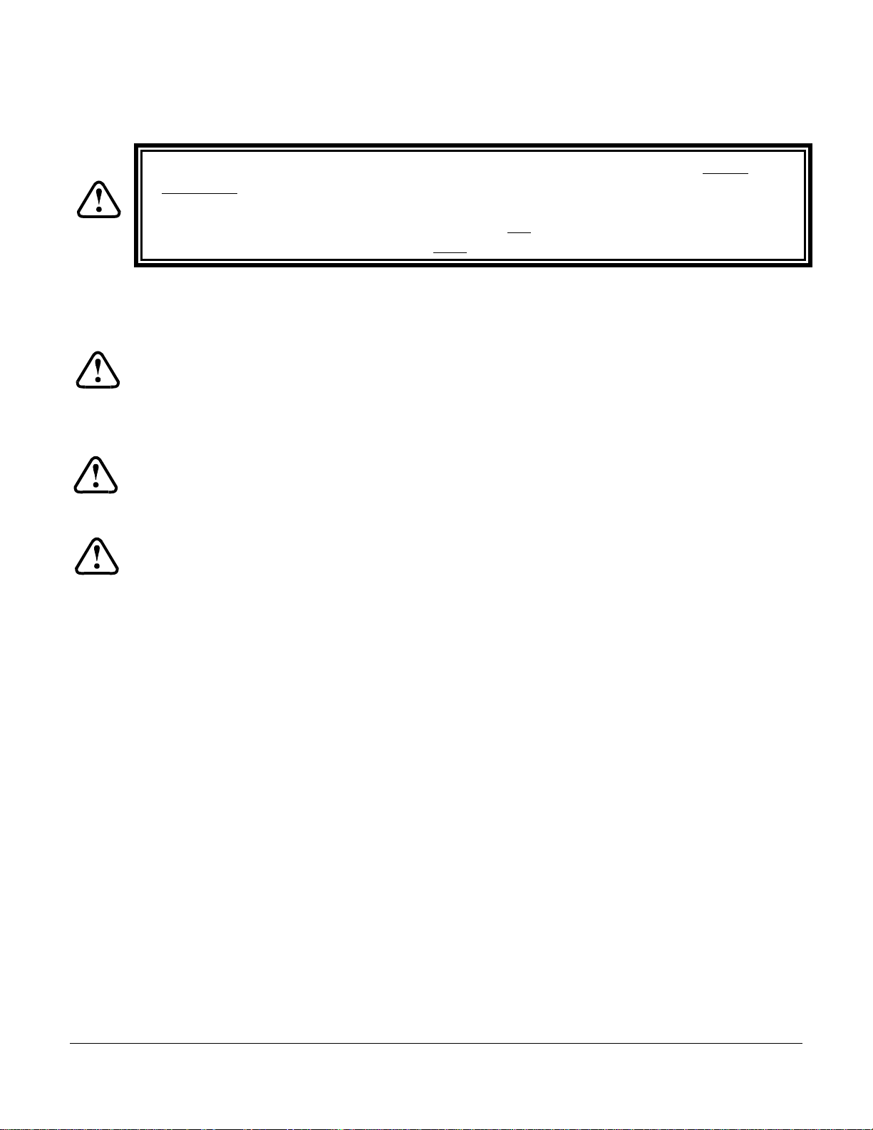
INSTALLATION NOTES:
1.
USE #20 AWG FOR POWER AND GROUND WIRES TO SERVO
(PINS 1 AND 9 ON 9-PIN CONNECTOR J201)
AND WIRE TO AUTOPILOT MASTER AND SINGLE-POINT GROUND.
ALL OTHER WIRING #20 TO #24 AWG.
2.
INSTRUMENT LAMP DIMMER CONTROL IS OPTIONAL.
12V SYSTEMS: CONNECT J101 PIN 4 TO DIMMER CONTROL AND J101 PIN 18 TO GROUND.
28V SYSTEMS: CONNECT J101 PIN 18 TO DIMMER CONTROL ( J101 PIN 4 NO CONNECT ).
REVERSAL OF ROLL SERVO DIRECTION CAN BE
3.
ACCOMPLISHED IF NECESSARY BY SWAPPING
WIRES ATPINS4 AND 5 OF THE
SERVO CONNECTOR (J201).
AIRCRAFT
ELECTRICAL
GROUND ( - )
INSTRUMENT LAMP
DIMMER (See Note 2)
(OPTIONAL REMOTE SPST PUSHBUTTON)
TOGGLE GPSS MODE
GPSS OPTION
ONLY
AUX RS-232 (FOR FUTURE EXPANSION)
CONTROL WHEEL SWITCH
PROGRAMMER MODULE
FROM GPS RECEIVER
PRIMARY SERIAL INPUT
GPSS OPTION
ONLY
ARINC-A
{
ARINC-B
DIGIFLIGHT-100 EXTERNAL WIRING DIAGRAM
1 2 3 4 5 6 7 8 9 10 11 12 13 14 15 16 17 18 19
J101 37-PIN FEMALE
D-SUBMINIATURE
(View Facing Rear of unit)
20 21 22 23 24 25 26 27 28 29 30 31 32 33 34 35 36 37
162738495
ROLL SERVO
J201 9-PIN FEMALE
D-SUBMINIATURE
NOTE
3
DigiFlight Autopilot Installation Manual TruTrak Flight Systems
March 2002 Printing 14
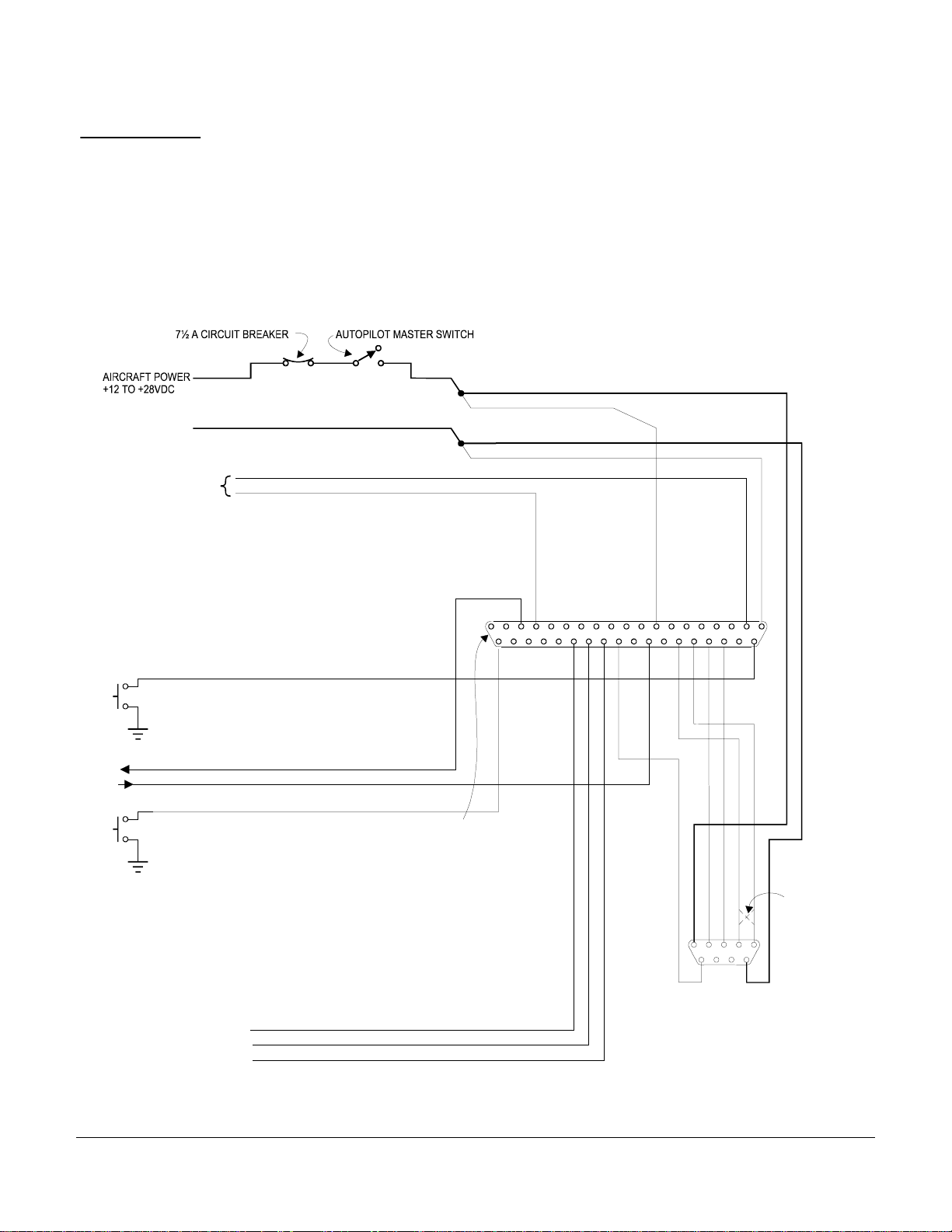
Page 17
D
INSTALLATION NOTES:
1.
USE #20 AWG FOR POWER AND GROUND WIRES TO SERVOS
(PINS 1 AND 9 ON 9-PIN CONNECTORS J201 AND J301)
AND WIRE TO AUTOPILOT MASTER AND SINGLE-POINT GROUND.
ALL OTHER WIRING #20 TO #24 AWG.
2.
INSTRUMENT LAMP DIMMER CONTROL IS OPTIONAL.
12V SYSTEMS: CONNECT J101 PIN 4 TO DIMMER CONTROL AND J101 PIN 18 TO GROUND.
28V SYSTEMS: CONNECT J101 PIN 18 TO DIMMER CONTROL ( J101 PIN 4 NO CONNECT ).
ROLL SERVO ONLY:
3.
REVERSAL OF SERVO DIRECTION CAN BE
ACCOMPLISHED IF NECESSARY BY SWAPPING
WIRESATPINS4AND5OFTHE
SERVO CONNECTOR (J201).
AIRCRAFT
ELECTRICAL
GROUND ( - )
INSTRUMENT LAMP
DIMMER(See Note 2)
J301 9-PIN FEMALE
D-SUBMINIATURE
PITCH SERVO ONLY:
4.
REVERSAL OF SERVO DIRECTION CAN BE ACCOMPLISHE
AS NECESSARY BY INSTALLING OR REMOVING A JUMPER
BETWEEN PINS 1 AND 2 OF THE 37-PIN CONNECTOR
( CUSTOMER'S J101 MATING PROGRAMMER P101 ).
PITCH SERVO
162738495
(OPTIONAL REMOTE SPST PUSHBUTTON)
TOGGLE GPSS MODE
GPSS OPTION
ONLY
AUX RS-232 (FOR FUTURE EXPANSION)
CONTROL WHEEL SWITCH
PROGRAMMER MODULE
FROM GPS RECEIVER
PRIMARY SERIAL INPUT
GPSS OPTION
ONLY
ARINC-A
{
ARINC-B
NOTE 4
12345678910111213141516171819
J101 37-PIN FEMALE
D-SUBMINIATURE
(View Facing Rear of unit)
20 21 22 23 24 25 26 27 28 29 30 31 32 33 34 35 36 37
162738495
ROLL SERVO
J201 9-PIN FEMALE
D-SUBMINIATURE
NOTE
3
DIGIFLIGHT-200 / 200 VS EXTERNAL WIRING DIAGRAM
TruTrak Flight Systems DigiFlight Autopilot Installation Manual
15 March 2002 Printing
Page 18

Page 19

TRUTRAK FLIGHT SYSTEMS
1500 S. Old Missouri Road
Springdale, AR 72764
Ph: 479-751-0250 Fax: 479-751-3397
www.trutrakflightsystems.com
info@trutrakflightsystems.com
 Loading...