

Page 1
Installation Manual
For
8300-013 Rev C
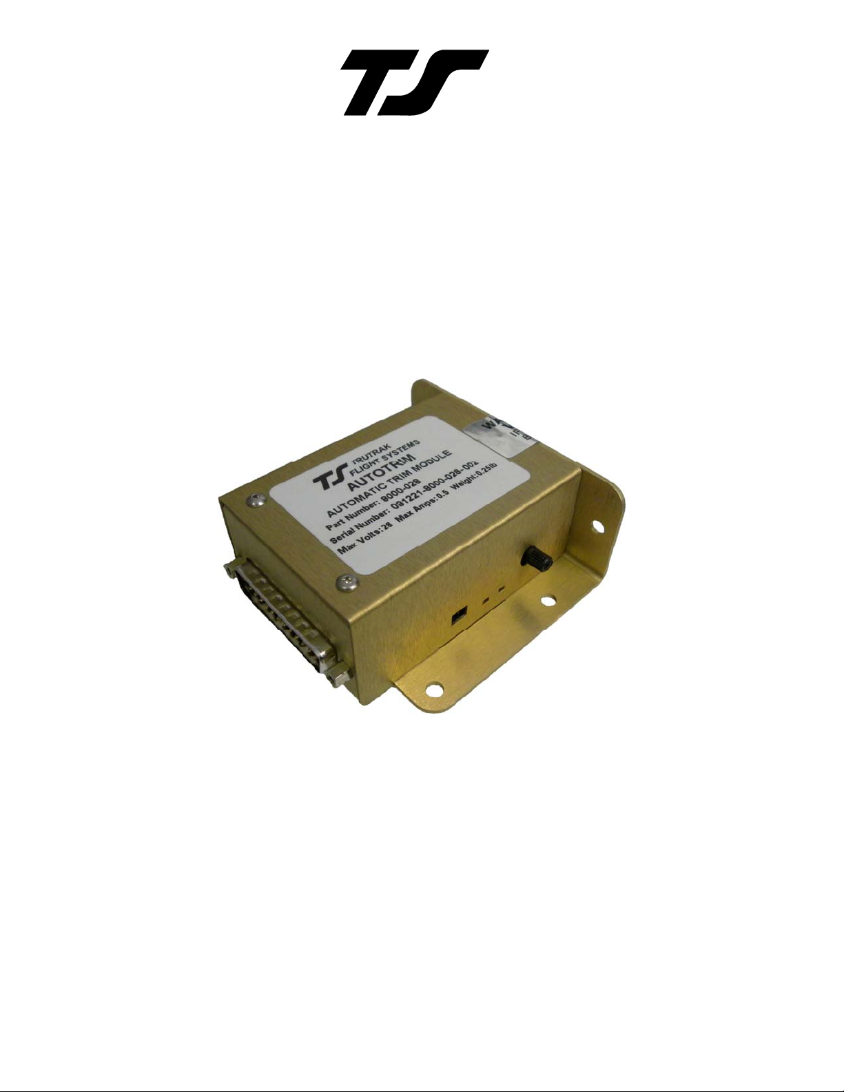
Automatic Pitch Trim
TRUTRAK FLIGHT SYSTEMS
1500 S. Old Missouri Road
Springdale, AR 72764
Ph: 479-751-0250 Fax: 479-751-3397
www.trutrakap.com
Page 2

IT IS THE INSTALLERS RESPONSIBILITY TO ENSURE
THAT THE TRIM SYSTEM DOES NOT EXCEED THE
ABILITY OF THE PILOT TO CONTROL THE AIRCRAFT AT
ANY SPEED WITH THE TRIM TAB AT FULL DEFLECTION
IN EITHER POSITION.
IF UNABLE TO MAINTAIN FLIGHT CONTROL WITH THE
TRIM TABS AT FULL DEFLECTION THEN STOPS WILL BE
NEEDED IN THE AIRCRAFT TRIM SYSTEM.
Page 3

Table of Contents
Electrical Pin-Out.................................................................................................................1
Automatic Pitch Trim Ground Checkout..........................................................................2
Retrofit to existing autopilot harness.................................................................................3
Pitch Auto Trim Block Diagram.........................................................................................3
Roll Auto Trim Block Diagram ..........................................................................................4
28 Volt Aircraft with 12 Volt Trim System .......................................................................4
Manual Auto Trim Switching.............................................................................................5
Trouble Shooting..................................................................................................................5
RETURN MERCHANDISE POLICY...............................................................................6
Revision Date Discription Pages
C 12/22/2009 New auto trim module All
Page 4

Electrical Pin-Out
The table below provides a brief explanation of each pin function on the 25-pin connector P101.
P101 Pin Function Notes
1 No Connection. Reserved for future expansion.
2 No Connection. Reserved for future expansion.
3 Pitch Servo Trim Sensor. Pitch servo trim sensor output to autopilot programmer. @2.5 v AP engaged no load
4 Pitch Servo Trim Sensor. Pitch servo trim sensor input from pitch servo pin 7. @2.5 v AP engaged no load
5 Torque Control. Pitch servo torque control input from autopilot programmer. @5 volt, AP engaged
6 Torque Control. Pitch servo torque control output to pitch servo. @5 volt, AP engaged
7 No Connection. Reserved for future expansion.
8 Trim Switch 1. Line 1 to existing trim switch.
9 Motor 1. Line 1 to existing trim servo motor. Will not control relays Voltage in @max 5 amps
10 Motor 2. Line 2 to existing trim servo motor. Will not control relays Voltage in @max 5 amps
11 Trim Switch 2. Line 2 to existing trim switch.
12 Power. Connects to autopilot master or pitch servo power line from programmer. 11 – 35V input
13 Power. Connects to pitch servo pin 1.
14 Ground. Ground connection to link sensor.
15 Ground. Connect to aircraft ground. Aircraft ground
16 Ground. Ground connection to pitch servo pin 9.
17 No Connection. Reserved for future expansion.
18 PH1P. Servo drive line output to pitch servo pin 3.
19 PH1P. Servo drive line input from programmer
20 PH1N. Servo drive line output to pitch servo pin 2.
21 PH1N. Servo drive line input from programmer
22 PH2P. Servo drive line output to pitch servo pin 5.
23 PH2P. Servo drive line input from programmer
24 PH2N. Servo drive line output to pitch servo pin 4.
25 PH2N. Servo drive line input from programmer
1
2345678910111213
14 15 16 17 18 19
20 21 22 23 24 25
25-Pin Connector P101
The Auto Trim controller MUST be wired directly to the aircraft trim motor. If the aircraft
manual trim system uses a relay system the Auto Trim connects on the motor side of the
relay system.
Total Weight Voltage Current Trim Motor Output
.5 LB 11 V – 35 V .25 A – 5 A Input voltage / 5 Amps
Auto Trim Installation Manual 1 TruTrak Flight Systems
December 2009 8300-013 Rev C
Page 5
N
N
N
Automatic Pitch Trim Ground Checkout
Power up autopilot.
Red light ON auto trim module at #1
small slot
Engage autopilot
Red light OFF on the auto trim
module at #1 small slot
Apply up elevator pressure.
Is servo holding the
controls
Yes
Does Automatic Pitch Trim run the trim servo?
#2 small slot light will flash red or green
Check torque wire. Pins 5 or 6
must be >2.5 volts AP engaged.
o
o
Yes
Does trim servo run in the
correct direction (up trim
tab) so as to trim up?
Yes
Check to ensure that trim
servo will run in both
directions by applying
Flip the switch located in large
slot on th e Automatic pitch trim
Check trim motor control or trim sense wires.
Pins 9 & 10 must go to trim motor.
Pin 4 must go to pitch servo pin 7
o
Module
down elevator as well
Note: If the above technique has been completed and the automatic trim module still does not run the trim, then first
try applying more force to the system when holding the up elevator. If the pitch servo slips easily when holding the
force, ensure that the pitch servo torque is set at the maximum value and hold as much force as possible without
slipping the servo. If the torque is set at the maximum and the system still does not function, check automatic trim
wiring.
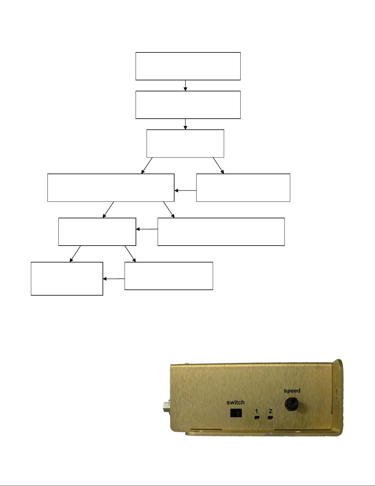
The switch in the first slot of the controller is to
switch trim motor direction, see above diagram.
Two small slots are control indication Led’s, see
above.
Potentiometer located on the side of the controller
is used to adjust the speed of trim motor rate of
change, clockwise rotation to increase speed. Too
little of rate will cause trim indicator to show on
auto pilot display. If rate setting is too fast then
aircraft will hunt in pitch.
Auto Trim Installation Manual 2 TruTrak Flight Systems
December 2009 8300-013 Rev C
Page 6

Retrofit to existing autopilot harness
Pitch Auto Trim Block Diagram
Auto Trim Installation Manual 3 TruTrak Flight Systems
December 2009 8300-013 Rev C
Page 7

Roll Auto Trim Block Diagram
28 Volt Aircraft with 12 Volt Trim System
The Voltage that is supplied to the Auto Trim system will drive the trim motor with the same voltage
when the Auto Trim system is in operation. The pitch servo and the auto trim system do NOT need to be
supplied with the same voltage to work correctly.
Auto Trim Installation Manual 4 TruTrak Flight Systems
December 2009 8300-013 Rev C
Page 8

Manual Auto Trim Switching with Auto Pilot Engaged
Trouble Shooting
Problem Cause Corrective Action
Trim motor will not move
with control pressure and
manual trim control is
functional
Trim motor will not move
& manual trim control
nonfunctional
Trim motor only runs in
one direction
Trim bar briefly shows on
autopilot display
Aircraft hunts up & down
in pitch
No aircraft voltage and/or
torque voltage to auto trim
system
Trim sense voltage incorrect
with auto pilot engaged
from pitch servo pin 7
Auto trim motor control
wires not connected to trim
motor (relays).
Auto trim controller speed
too slow
Auto trim controller speed
too high
Correct power, ground, &
torque wiring
Engage auto pilot before
testing
Check 2.5 voltage at pin 3 or 4
Voltage will increase or
decrease with elevator
pressure
Auto trim motor control wires
must be connected to the trim
motor only.
Rotate knob on controller
clockwise
Rotate knob on controller
counter clockwise
Auto Trim Installation Manual 5 TruTrak Flight Systems
December 2009 8300-013 Rev C
Page 9

RETURN MERCHANDISE POLICY AND PROCEDURE
Under no circumstances should products be ret ur ned to Tru T rak without first obtaining a Return of Merchandise Authorization
number (RMA #) from TruTrak. An RMA # may be obtained by contacting us at 866-878-8725.
Products that do not have an RMA # will not be processed.
Please include some form of documentation stating the reason for the return and describing any symptoms, failure modes,
suspected causes of damage, diagnostics performed, data collected, etc.
Product(s) should be packaged in their original shipping containers. In lieu of this, they should be very carefully packaged in
containers suitable to protect them during transit. Note that damage caused during shipping will not be repaired under
warranty.
The outside of the box must be clearly marked with the RMA # issued by TruTrak and the RMA # must also be noted on the
return documents.
Products will be returned to the customer at no charge via FedEx Ground or UPS Ground. If customer requests expedited
shipping (2
nd
Day or Overnight) they will be charged the shipping cost and must supply a credit card number.
Send ALL return shipments to:
Trutrak Flight Systems, Inc.
1500 South Old Missouri Road
Springdale, AR 72764
USA
Attention: Returns Dept.
RMA# ______________
Warranty On TruTrak Flight Systems Products
We here at TruTrak Flight Systems know how important it is to feel as though the customer is purchasing a product
that the manufacturer is going to stand behind. For this reason we want offer more than the basic one year
warranty that is standard to this industry. The warranty on all TruTrak products will be three years from the date of
purchase. Abuse and misuse of a product are not covered under this warranty. Modification to a product may void
the warranty, as well as carry a penalty when upgrading to another product. This three year warranty will be for all
products except the Pictorial Turn & Bank, which will continue to have a warranty of one year from the date of
purchase.
TruTrak Flight Systems No Penalty Upgrade Policy
As the product line continues to grow, it becomes increasingly difficult to maintain a simple upgrade policy. We do
want to reward our repeat customers by allowing a lower cost upgrade from one system to another; however we
are not able to offer this across the board on all products. If you are considering an upgrade, please call and we
will give you a quote on what this would cost. Many products that we sell today are upgradeable for only the
difference in system price. Because we continually strive to have the most up to date products possible, we
occasionally have to discontinue products. We will continue to offer discounted upgrades even for our discontinued
products.
Auto Trim Installation Manual 6 TruTrak Flight Systems
December 2009 8300-013 Rev C
Page 10

Auto Trim Installation Manual 7 TruTrak Flight Systems
December 2009 8300-013 Rev C
Page 11

THIS PAGE UNINTENTIONAL LEFT BLANK
Auto Trim Installation Manual 8 TruTrak Flight Systems
December 2009 8300-013 Rev C
Page 12

TRUTRAK FLIGHT SYSTEMS
1500 S. Old Missouri Road
Springdale, AR 72764
Ph: 479-751-0250 Fax: 479-751-3397
Toll free: 866-TRUTRAK
866-(878-8725)
www.trutrakap.com
 Loading...