

Page 1
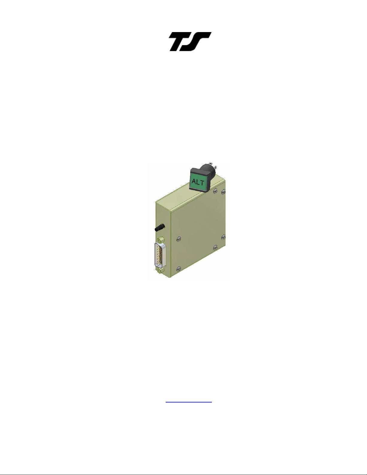
Altrak Altitude Hold &
Altrak VS Altitude Hold
Installation & User Guide
8300-014 Rev B
TRUTRAK FLIGHT SYSTEMS
1500 S. Old Missouri Road
Springdale, AR 72764
Ph. 479-751-0250 Fax 479-751-3397
www.trutrakap.com
Page 2

Revision
Date Description
Page #
INSTALLATION MANUAL
For
Altrak VS & Altrak Altitude Hold
TABLE OF CONTENTS
Mechanical Considerations ...................................................................................... 1
RFI/EMI considerations ........................................................................................... 2
Altrak Programmer Mounting / Setup / Ground Test ............................................ 2
Altrak VS control panel installation ........................................................................ 3
Power Up ................................................................................................................... 3
Basic Altrak Operation ............................................................................................. 4
Altrak VS Operation................................................................................................. 5
Electrical Pin out ....................................................................................................... 6
Altrak Wiring Diagram ............................................................................................ 7
Altrak VS Wiring Diagram ...................................................................................... 8
Trouble Shooting ...................................................................................................... 9
Installation Diagram ................................................................................................11
Assembly Diagram ...................................................................................................12
RETURN MERCHANDISE POLICY AND PROCEDURE ... Error! Bookmark not
defined.
A
B 01/10/2009 New schematics & Installation notes 7 - 12
07/01/2008 Initial Release
Page 3
Mechanical Considerations
The installation information in this section is extremely important and
must be clearly understood by the installer. Improper servo installation
or failure to observe and diagnose installation problems prior to flight
can result in extremely serious consequences, including loss of ability
to control the aircraft. If there are any questions on the part of the
installer it is mandatory to resolve these questions prior to flight of the
aircraft.
Most modern experimental aircraft use push-pull tubes to drive the primary controls. These tubes generally
have a total travel of 3" or less; therefore, it is best to connect the autopilot servo to the primary control by the
same method. This connection consists of an arm on the servo connected by a push-pull rod to the primary
control. Rod-end bearings are required on each end of the push-pull rod.
The servo arm must not rotate even near to the point called OVER CENTER, the point at which the
primary aircraft control would lock up. Some aircrafts mechanical primary control installations will not
allow this to occur and do not need the servo stops.
This is a condition that would result from the servo being back driven when the pilot operates the
controls, or from the servo itself driving the controls to a stop. To protect against this mechanical
stops are supplied with the servos. These stops are drilled so that they can be mounted at different
angles as required (18° intervals).
In addition to the proper use of the stop it is important to know the amount of travel on the primary
control that the servo can handle. With the push rod connected to the outer most hole (1 1/2") the
travel on the primary can not exceed 2 1/2", the intermediate hole 2 1/16", and the inner hole 1 5/8".
It is important to note that the servo travel should be very nearly the same in both directions. In most
cases this means that the servo arm needs to be perpendicular to the push rod but there are
exceptions such as the RV-4 and RV-8 installations.
There will be installations in which space does not permit the use of the stop. When this is done the
aircraft's primary control stops must be positive and care must be taken to be sure that the servo
drives the push rod the same distance in both directions, and that the travel limits of the servo arm
are not exceeded.
There are installations in which the travel of the push-pull tube exceeds the allowable 2 1/2". For such
installations, the drive can be applied to a bell crank at a radius point that moves the desired 2 1/2" of
maximum allowed travel in the outer most hole of the arm.
When there is no way to have a drive point of less than 2 1/2" or when the primary control is cable-driven it is
necessary to use the capstan-cable servo drive. When this is done the servo should be mounted so that the
1/16" diameter cable which wraps around the capstan when extended parallel to the primary cable is
approximately 3/16" from the primary cable. If the primary control travel does not exceed 5" the cable-locking
pin will be 180° away from the point at which the cable leaves the capstan. When the primary control is at the
neutral point this means the total cable wrap around the capstan is 360°. If the primary control travel is
greater than 5" the cable wrap is 720°and the pin is adjacent to the output point when the primary control is at
the neutral point. The cable clamps when properly installed will not slip and thus get loose, but it is desirable
to nico press or swedge a fitting onto the cable so as to provide added assurance that the cable will not
become slack. If the bridle cable is not sufficiently tight there will be lost motion in the autopilot drive. This
will result in hunting (oscillation).
TruTrak Flight System 1 Altrak Installation & User Guide
January 2009 8300-014 Rev B
Page 4

RFI/EMI considerations
The autopilot programmer is shielded and does not generate any appreciable level of electromagnetic
interference. More over, the servo lines (except for power and ground) are low-current and cannot contribute
to RF interference. The servo power and ground lines do have switching currents through them, but so long
as there are no parallel runs of servo power and ground lines with such things as poorly-shielded antenna
lines or strobe light power lines, there is no need to shield the servo harnesses.
The autopilot itself has been internally protected from RF interference and has been tested under fairly
extreme conditions, such as close proximity to transmitting antennas. However, it is always good practice to
insure that such antennas are properly shielded and not routed directly over or under sensitive panel-mounted
electronic equipment. Most problems in this area are the result of improper RF shielding on transmitting
antennas, microphone cables, and the like. The most sensitive input to the autopilot is the Control Wheel
Switch input. This line should not be routed in parallel with transmitting antennas or other sources of known
RF interference. If necessary, it can be shielded with the shield connection to pin 15 of the autopilot
connector.
Altrak Programmer Mounting / Setup / Ground Test
Must be performed before first flight
After the servo is installed check to see which direction the servo turns to move the elevator up. If the servo
turns counter-clockwise (when looking at the servo arm or capstan) to drive the elevator up then no jumper is
necessary on the programmer. If the servo turns clockwise for elevator up then the pitch servo reverse
jumper must be installed. See Pin 4 on the wiring table for instructions on how to wire the pitch servo reverse
jumper.
The programmer has a static port located next to the connector. The static port can be connected to the
static system. For pressurized aircraft it is necessary that the static system be connected to the Altrak static
port. For most other aircraft the static connection is optional.
Before mounting the Altrak it should be tested for proper operation. After the servo installation and wiring are
complete and the Altrak programmer is plugged in, the test can be performed. When the Altrak is powered-up
it is necessary that the Altrak be stationary. The attitude of the programmer is not important during the
power-up phase. With the Altrak programmer secured turn on the master switch and avionics master so the
Altrak has power. During the power-up phase of operation (the first ten seconds that the Altrak has power)
the ALT button will flash. Next engage the Altrak by pressing the ALT button. With the THIS SIDE RIGHT
sticker facing you rotate the programmer module clockwise to simulate a nose down attitude. The servo
should cause the elevator to move up to correct for the simulated nose down attitude. Rotating the
programmer counter-clockwise should drive the elevator down.
Mounting the programmer module of the Altrak can be done in any location; the only requirement that must be
met is that the side of the unit label "This side right" must face the right side of the aircraft. This is also the
side that has six (6) screws on the surface. The rotational position is not important as long as the right side is
facing right. The side with the sticker also must be parallel with the direction of flight. The mounting holes on
the programmer are 1-1/2 inches apart, and are tapped for a 6-32 thread, use any screw length up to 1" in
length. The engage/disengage pushbutton which also serves as the enunciator can be mounted anywhere in
the panel.
The activity setting (activity is the amount of servo movement for a given amount of programmer movement)
in all RV type aircraft will be at medium activity setting. If more or less activity is required, it is necessary to
use a jumper as per the wiring diagram to change the activity setting.
MOVE TAIL UP AT LEAST A FOOT AND ELEVATOR MUST
MOVE UP AT SAME TIME. MOVE TAIL DOWN AT LEAST A
FOOT AND ELEVATOR MUST MOVE DOWN AT SAME TIME.
TruTrak Flight System 2 Altrak Installation & User Guide
January 2009 8300-014 Rev B
Page 5
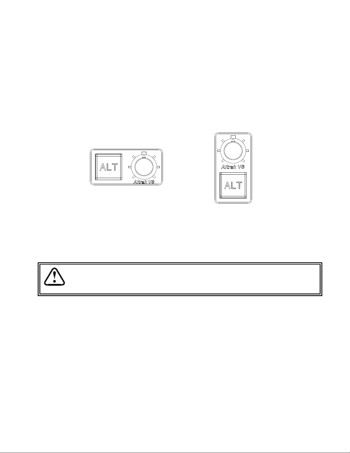
Altrak VS control panel installation
The Altrak VS comes with a reversible control panel, which can be mounted either horizontally or vertically.
The engage/disengage button requires a 5/8” diameter hole; the same size hole can be used for the mounting
of the VS control knob. A template for the two holes is included with this manual. When putting the knob on
the VS control potentiometer, the pointer must be pointing at the larger white mark on the control panel. This
is shown below for both the horizontal and vertical mounting orientations.
Power Up
When powering up the autopilot ensure that the aircraft is still
for 10 seconds.
The power up of the autopilot takes approximately ten seconds. During the power up cycle it is very
important that the aircraft be as still as possible for the initialization of the internal gyro. While the
autopilot is in the power up phase, the enunciator will flash rapidly for approximately ten seconds. Once the
power up phase is completed, the enunciator will remain unlit.
TruTrak Flight System 3 Altrak Installation & User Guide
January 2009 8300-014 Rev B
Page 6

Basic Altrak Operation
Once the aircraft is at the desired altitude, and trimmed for level flight, the altitude hold can be engaged.
Pushing the ALT button will engage the Altitude hold. If in severe turbulence or when the aircraft is out of trim
and the servo may run out of torque, in this case the current altitude and the selected altitude may be
different. When the difference between the current altitude and the initial selected altitude is more than
approximately 50 feet the light in the switch will flash, rapid flashing of the light for below altitude and slow
flash of the light for above altitude. If an out of trim condition is suspected, disengage the altitude hold, re-trim
the aircraft, and re-engage the altitude hold. If turbulence is the cause for the altitude departure the Altrak will
fly back to the desired altitude automatically.
Changing the desired altitude can be done by simply disengaging the altitude hold, flying to the desired
altitude and re-engaging by pushing the ALT button. If on a long flight setting the barometer to the local
setting will result in a difference in indicated altitude and the altitude selected by the Altrak. To correct the
altitude error, disengage the altitude hold, fly to the new desired altitude and re-engage the altitude hold.
If the optional trim sensing pitch servo has been purchased, the Altrak will enunciate the need to trim the
aircraft, with a rapid flash of the light in the switch for the need to trim up, and a slow flash of the light in the
enunciator for the need to trim down. If the Altrak is coupled with a Digitrak / Pictorial Pilot, the Altrak can only
be engaged if the Digitrak / Pictorial Pilot are engaged. When the control wheel switch is pushed, the Digitrak
/ Pictorial Pilot will enter control wheel steering mode as normal, but the Altrak will remain engaged and
holding altitude while the pilot manually flies the aircraft to the desired track. Upon release of the control
wheel switch the Digitrak / Pictorial Pilot will re-engage and synchronize to the track being flown at the time,
and the Altrak will remain engaged throughout the maneuver. It should be noted that the Altrak will lose some
altitude while the aircraft is turning. The altitude loss could be as much as 50 to 100 feet depending upon the
bank angle. The Altrak will recover the lost altitude on it's own after the turn is completed, or if the aircraft is
in a sustained turn.
Because Altrak does not receive bank angle information, it will lose some
altitude in turns. If the bank angle is less than 30 degrees the altitude loss will
be less than 50 feet, for this reason it is recommended that the bank angle be
kept below 30 degrees.
TruTrak Flight System 4 Altrak Installation & User Guide
January 2009 8300-014 Rev B
Page 7

Altrak VS Operation
Note: Zero vertical speed (Altitude hold) must be selected or Altrak VS will NOT engage.
To engage the Altrak VS, ensure that zero vertical speed is selected on the VS control knob (The VS control
knob should be at the center detent.) Push the ALT button to engage the Altrak VS. When Altrak VS is
engaged it will be in altitude hold mode. If the aircraft is out of trim the light in the Altrak engage/disengage
button will enunciate the need for trim, with a rapid flashing of the light for trim up, and a slow flashing of the
light for trim down.
If Altrak is coupled with the Digitrak / Pictorial Pilot, the Altrak can only be engaged if the Digitrak / Pictorial
Pilot are engaged. When the control wheel switch is pushed, the Digitrak / Pictorial Pilot will enter control
wheel steering mode as normal, but the Altrak will remain engaged while the pilot manually flies the aircraft to
the desired track. Upon release of the control wheel switch the Digitrak / Pictorial Pilot will re-engage and
synchronize to the track being flown at the time, Altrak will remain engaged throughout the maneuver. It
should be noted that if Altrak is in altitude hold during this maneuver, it will lose some altitude while the
aircraft is turning. The altitude loss could be as much as 50 to 100 feet depending upon the bank angle. The
Altrak will recover the lost altitude on its own after the turn is complete.
Changing the desired altitude can be done by simply rotating the VS control knob to the right to command a
vertical speed climb, or to the left to command a vertical speed descent. The maximum possible vertical
speed in either direction is approximately 800 feet per minute. As when in the altitude hold mode, the Altrak
VS will always enunciate the need for trim, with a rapid flashing for trim up, and a slow flashing for trim down.
TruTrak Flight System 5 Altrak Installation & User Guide
January 2009 8300-014 Rev B
Page 8

Electrical Pin-Out
P101
Function
Notes
1 Autopilot Master
(+12 to +14 V DC). The autopilot itself draws less than 0.3 ampere.
See note 3 on wiring
2 Control Wheel Switch
. Connect as shown in wiring di
See note 3 on wiring
3 On / Off Switch
. Connects to the illuminated push button module
4 Pitch Reverse Jumper
,
Direction of the servo arm / capstan rotation
See note 2 on wiring
5 Pitch Servo Trim Sensor.
A signal from the pitch servo to the autopilot which indicates
6 Engage Lamp /
LED
Connects to
LED which connects to
470 ohm resistor
. See Module Rear View
7 Pitch Servo Torque Control
. A signal from the autopilot to the pitch servo which sets
8 VS control
inpu
t from button assembly on panel.
VS Option only
9 AP On
. Connect to pin 7 on
Digitrak / Pictorial Pilot
/Pictorial Pilot (This function is
See note 3 on wiring
10
Activity Select
. Connect to ground for low activity, leave open for medium activity, and
See note 4 on wiring
11
Pitch Servo control lines
. These lines cause the stepping motor in the pitch servo to run
Do
NOT
attempt to
15 Ground Connection
. Provide #20 AWG to common grounding point.
The table below provides a brief explanation of each pin function on the main 15-pin connector P101.
Pin
Most of the current required by the system is used by the servo (up to 1Amp depending
on torque setting).
agram to a SPST momentary
switch located remotely to the autopilot for convenient disengage function.
present or absent, as follows:
Pin 4 open ( no connection) Servo CCW (counter-clockwise) → UP
Pin 4 Jumpered to pin 15 Servo CW (clockwise) → UP
an out-of-trim condition and its direction. (For use with trim sensing servo upgrade)
the amount of torque to be delivered by the servo.
only to be used if Altrak is coupled to Digitrak / Pictorial Pilot/Pictorial Pilot.)
connect to 12v for high activity
( as viewed from face of the servo body) for
UP elevator
diagram
diagram
diagram
on wiring diagram
diagram
diagram
in the appropriate direction at the desired velocity. They are small-signal lines and do not
12
have any substantial current-carrying capability or require any special shielding. Connect
13
to pitch servo as shown on wiring diagram.
14
TruTrak Flight System 6 Altrak Installation & User Guide
January 2009 8300-014 Rev B
reverse servo direction
by swapping wires
Page 9

BASIC ALTRAK WIRING DIAGRAM
TruTrak Flight System 7 Altrak Installation & User Guide
January 2009 8300-014 Rev B
Page 10

ALTRAK VS WIRING DIAGRAM
TruTrak Flight System 8 Altrak Installation & User Guide
January 2009 8300-014 Rev B
Page 11

ALT
ALT
Trouble Shooting
Problem Cause Corrective Action
LED will not blink
when power applied
LED blinks but will
not light up when pressed
ALT VS will not engage (
ALT LED light up)
No aircraft voltage and/or
ground to system
Engage signal not received
at module or DT/PP not
engaged if connected pin 9
Engage signal not received
at module or VS knob not
Correct power, ground
wiring
Check for low (ground) at
pin 3 when ALT switch
depressed
See above and/or check for
2.5 v at pin 8 at module
centered (2.5 v)
Aircraft pitches up or
down rapidly
Aircraft hunts up and
down
Weight of Module, switches, wires: .5 lb
Weight of servo 2.5 lb
Max voltage 14 volts
Max current with servo engaged 2 amps
Pitch servo is reversed Install or remove jumper to
ground pin 4
Activity not correct See note 3 (slow hunt
increase activity)
TruTrak Flight System 9 Altrak Installation & User Guide
January 2009 8300-014 Rev B
Page 12

This page unintentionally left blank
TruTrak Flight System 10 Altrak Installation & User Guide
January 2009 8300-014 Rev B
Page 13

Installation Diagram
TruTrak Flight System 11 Altrak Installation & User Guide
January 2009 8300-014 Rev B
Page 14

Assembly Diagram
TruTrak Flight System 12 Altrak Installation & User Guide
January 2009 8300-014 Rev B
Page 15

RETURN MERCHANDISE POLICY AND PROCEDURE
Under no circumstances should products be returned to TruTrak without first obtaining a Return of
Merchandise Authorization number (RMA #) from TruTrak. An RMA# may be obtained by contacting us at
866-878-8725.
Products that do not have an RMA # will not be processed.
Please include documentation stating the reason for the return and describing any symptoms, failure modes,
suspected causes of damage, diagnostics performed, data collected, etc.
Product(s) should be packaged in their original shipping containers. In lieu of this, they should be very
carefully packaged in containers suitable to protect them during transit. For your protection, items should be
insured for the full value. Note that damage caused during shipping will not be repaired under warranty.
The outside of the box must be clearly marked with the RMA # issued by TruTrak and the RMA # must also
be noted on the return documents.
Products will be returned to the customer at no charge via FedEx Ground or UPS Ground. If customer
requests expedited shipping (2nd Day or Overnight) they will be charged the shipping cost and must supply a
credit card number.
INTERNATIONAL SHIPMENTS:
Trutrak sends all International shipments with an insurance value on all products. Trutrak pays for shipping
only. The customer is responsible for any and all additional fees, duties, taxes associated with the shipment.
When sending products to Trutrak for repair or otherwise please be advised that the customer is responsible
for all charges and fees associated with shipment. For your protection, items should be insured for the full
value.
Trutrak states on all product returns “WARRANTY REPAIR AT NO CHARGE TO CUSTOMER.
A COMMERCIAL INVOICE VALUE OF $___ GIVEN FOR INSURANCE PURPOSES ONLY”
Please keep in mind that your government or another entity in your country may impose a charge for custom and/or
brokerage fees, duties and taxes on items received from the US. These charges do not originate from our company nor do
we benefit from them in any way. You are responsible for payment of all custom and brokerage fees, duties and taxes
that may be imposed when these goods are imported into your country.
Send ALL return shipments to:
TruTrak Flight Systems, Inc., 1500 South Old Missouri Road, Springdale, AR 72764 USA
Attention: Returns Dept. RMA#
Warranty On TruTrak Flight Systems Products
We here at TruTrak Flight Systems know how important it is to feel as though the customer is purchasing a
product that the manufacturer is going to stand behind. For this reason we want offer more than the basic one
year warranty that is standard to this industry. The warranty on all TruTrak products will be three years from
the date of purchase. Abuse and misuse of a product are not covered under this warranty. Modification to a
product may void the warranty, as well as carry a penalty when upgrading to another product. This three year
warranty will be for all products except the Pictorial Turn & Bank, which will continue to have a warranty of
one year from the date of purchase.
TruTrak Flight System 13 Altrak Installation & User Guide
January 2009 8300-014 Rev B
Page 16

TRUTRAK FLIGHT SYSTEMS
1500 S. Old Missouri Road
Springdale, AR 72764
POSTAL SERVICE ADDRESS
P.O. Box 189
Springdale AR 72765-0189
Ph: 479-751-0250 Fax: 479-751-3397
www.trutrakap.com
 Loading...