

Page 1
ADI Flight Instrument
Installation & User Guide
8300-016 Rev B
TruTrak Flight Systems
1500 S. Old Missouri Rd
Springdale, AR 72764
Toll Free: 866-TRUTRAK
Ph: 479-751-0250
Fax: 479-751-3397
www.trutrakap.com
Page 2

Table of Contents
ADI Operation ......................................................................................................... 1
ADI Installation ....................................................................................................... 2
ADI Backup Battery Servicing................................................................................ 2
ADI Pin-Out ............................................................................................................ 3
ADI Schematic ........................................................................................................ 3
ADI with Battery Backup ........................................................................................ 4
ADI Block Diagram................................................................................................. 4
ADI Backup Battery Block Connection .................................................................. 5
ADI Backup Battery PIN OUT................................................................................ 5
GPS Setup Guide ..................................................................................................... 6
TROUBLE SHOOTING GUIDE .......................................................................... 11
Revision Date Description Page #
A 07/01/2008 Initial Release
B 12/07/2009 Updated 12
Page 3

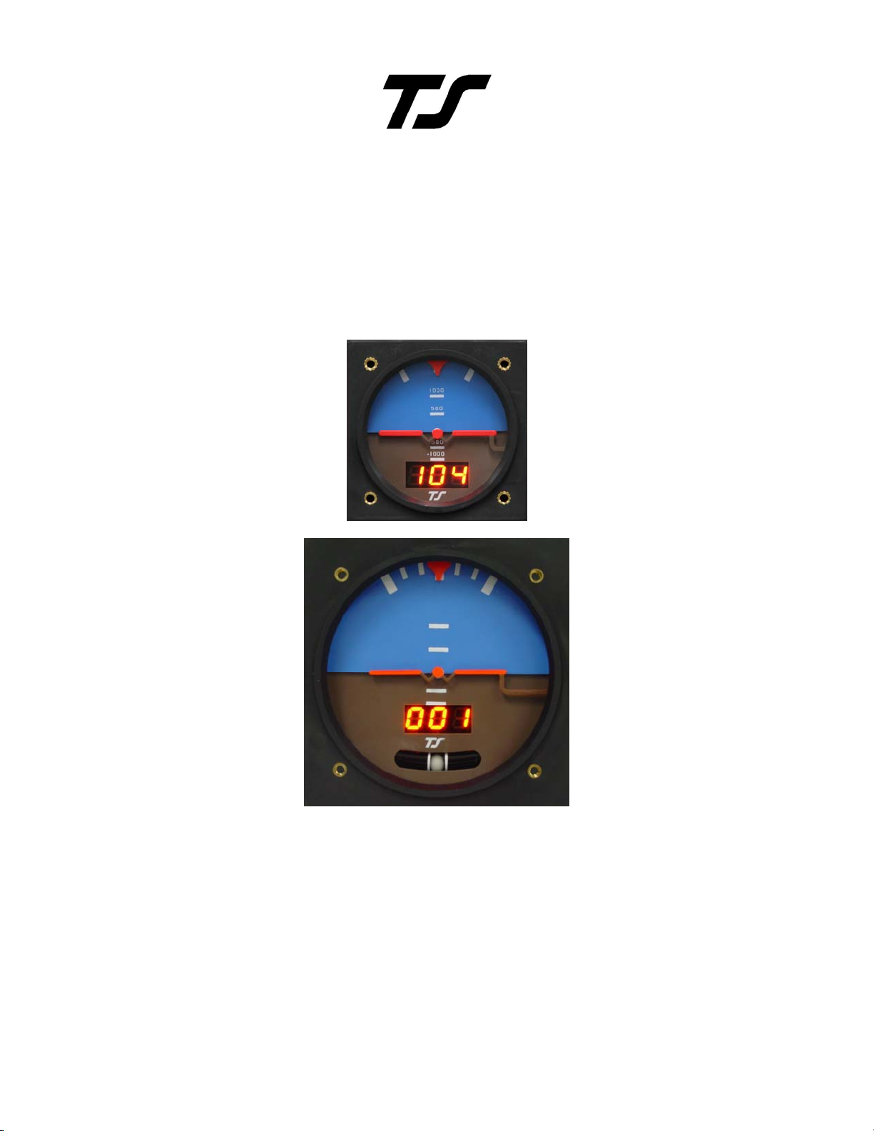
ADI Operation
The artificial horizon, when needed is without a doubt, the most important instrument in the panel. For this reason, the
display must be easy to fly and the instrument very reliable. To achieve this, the ADI combines modern solid state
technology with an easy to see uncluttered mechanical display. In the basic instrument flight panel it is intended for
installation between an airspeed indicator and an altimeter. It is also well suited as the conventional backup in panels
incorporating one of the large glass displays.
The ADI is easy to fly partly because it contains in one instrument, roll, pitch, and direction. Beyond this, it is the
content of each of these displays that make this instrument easy to fly.
The direction display is located in the center of the instrument just below the rotating horizon mask. As is often the case
with an inexperienced pilot caught in IMC, the instrument may be viewed with tunnel vision. For this reason it is good
to have the direction in the center of the tunnel. Of more importance is that this display is track instead of magnetic
heading in that the modern way to navigate is to fly track. When track is presented as a gyro display, the numbers move
sequentially one degree at a time. Experience is showing that direction control with this digital DG placed immediately
below the horizon mask is as easy to fly as the conventional vertical card DG in combination with the conventional
horizon placed nearby.
The bank angle display is driven in a manner similar to that used in the pictorial turn
and bank. The only difference is that in this instrument the display shows bank angle
instead of turn rate. The advantage of this is that the presentation is instantaneous
data only. It cannot drift to accumulate error as is possible with the more complex
AHRS driven systems. It shows bank angles of up to +/- 45° while the requirement
on conventional gyro horizons is +/- 100°. To compensate for this, in the 3 1/8” size
only, flashing red arrows point in the direction the stick is to be moved to level the
aircraft when the bank exceeds +/- 30°. Note that when flying on instruments the
object is to stay level or at least in shallow banks. This instrument is therefore
designed to keep the pilot out of trouble.
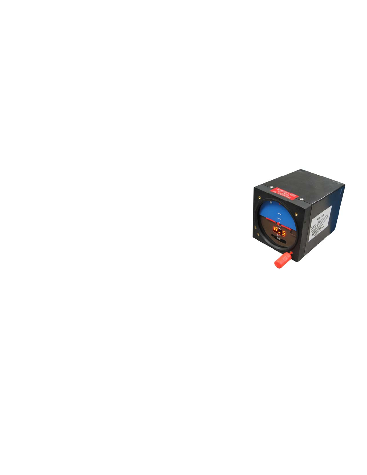
The pitch display is perhaps the most beneficial feature of the ADI when compared with conventional horizon
indicators. For short term or immediate movement of the nose up or down, this instrument responds and is flown like
any other gyroscopic pitch indicator. The difference is that after the display has moved in response to an attitude change
the deflection is sustained by the resulting vertical speed. As compared to a pitch attitude display, the vertical speed
display makes it easier to hold altitude and to maintain stable climbs and descents. Also, the movable airplane symbol
does not have to be adjusted to compensate for the angle the fuselage flies when vertical speed is zero. It is recognized
that an aircraft when at the limit of its altitude capability can fly at an ever increasing angle of attack when vertical
speed indicates zero. For this reason an airspeed warning in the form of the letters “A-S” flashing in the DG display is
provided. The answer to this situation is then to observe the airspeed indicator. For stall prevention airspeed is the best
information short of an angle of attack indicator. (Better than attitude)
Another plus regarding this display is that when the airplane is going straight or not turning a wing level presentation is
shown. With this presentation one can disregard the effect of the rudder being out of trim (ball off center) just as
crosswind is not a factor when flying GPS track for direction. This is easier than trying to fly straight with the display
showing a wing down as is the case with a conventional horizon display when the rudder is out of trim. To sum it up, all
of the features described above, in combination, provide what we believe to be the easiest to fly artificial horizon.
TruTrak Flight System 1 ADI Flight Instrument Installation Manual
December 2009 8300-016 Rev B
Page 4
ADI Installation
Power and ground connections can be made using 22 gage wire with a 2 amp circuit breaker between the avionics buss
and the ADI.
When the unit is purchased in its basic form, the instrument uses the serial output from a GPS (RS-232) for the DG
display. The DG will not display a heading until a ground speed of 5 to 10 knots is achieved.
When the unit contains the built-in GPS receiver, it is only necessary to connect the remote antenna and place the
antenna in view of the sky. On the initial start up it could take up to 15 to 30 minutes to find the satellites, after the
initial startup the GPS will find the satellites in about 5 min the center bar will flash after start up until the GPS receiver
finds the satellites. Then the bar will stop flashing and become steady, at this time the internal GPS is ready for flight.
The internal lighting feature is connected to the instrument panel light bus. The LED will dim to the lowest setting with
a low voltage on the dimmer wire. Confirm that the dimmer system drops to 0 volts when off or the display may stay
very dim and be hard to see in sunlight. The internal lighting is internally grounded.
Apart from the electrical connections, there are standard 1/8” pipe thread receptacles for both pitot and static lines.
Correct tightening is accomplished by starting the adapter by hand until unable to turn, then tightening ½ turn more with
a wrench. Unless the aircraft is pressurized, there is no need to connect the static
line. The airspeed signal is required for the attitude display to function correctly.
Also, it is there to provide the low airspeed warning. This warning is in the form
of the flashing letters “A-S” alternating with the DG number on the DG display
when the airspeed falls below the best rate of climb speed or whatever speed the
owner might choose. Setting of this air speed warning requires a flat blade
screwdriver small enough (approx. ⅛ shaft, tool provided) through the 6-32
female thread. The correct screw driver is provided with the unit.
The lower right instrument screw is removed to gain access to the airspeed
adjustment screw. The procedure for setting the airspeed warning is to fly the
aircraft at the best rate of climb speed (which is also the best glide speed and
attitude sustaining airspeed) or whatever speed suits the owner. While holding
this speed, rotate the adjustment so the flashing “A-S” just appears.
Mounting of the ADI is not angle sensitive as long as the tilt is not more than 10 degrees in any direction, so no
shimming is needed for panel tilt compensation. The mounting screws are 6-32 thread with a maximum length of 3/8”.
Brass screws are preferred.
3 1/8” ADI 3.4”H x 3.4”W x 4.6”D 12-28 volts - Weight - 14 oz
2 ¼” ADI 2.5”H x 2.5”W x 6.7”D 12-28 volts - Weight - 13 oz
ADI Backup Battery & Servicing
Switch label should state, “ADI BACKUP POWER” normally on the switch side that engages the battery
The servicing of the ADI backup battery is simply a matter of inspection of the functionality and confirming charge and
discharge rates.
Recommendation of a function test during the pre-takeoff checklist to confirm the LED switch illuminates with
activation of the backup battery. The ADI should function normally in this mode. Once it has been verified that the
backup battery is properly functioning, return the switch to the normal position.
Once a year a complete function test of the backup battery system is recommended:
Activate the ADI backup battery and confirm LED is illuminated. Continue in this mode, note the time of
activation and confirm minimum one hour function of the ADI.
If function time is less than one hour then remove backup battery and charge on the bench for a minimum of eight hours
and retry function test above.
TruTrak Flight System 2 ADI Flight Instrument Installation Manual
December 2009 8300-016 Rev B
Page 5
ADI Pin-Out
ADI Connector pin-out
Pin # I/O Connection Pin Function
1 I Power + AVIONICS DC Power (9-30 Volts DC)
2 I 24 V Dimmer controller 24V dimmer input
3 I 12 V Dimmer controller 12V dimmer input
4 I Future AOA module AOA (Future use)
5 -- No Connection Do not connect
6 I
7 -- No Connection Do not connect
8 -- No Connection Do not connect
9 I Aircraft Ground Main DC Ground
ADI Schematic
RS 232 Series Data in
O
RS 232 Serial Data out with Internal GPS
RS-232 input or
RS-232 output with internal GPS
TruTrak Flight System 3 ADI Flight Instrument Installation Manual
December 2009 8300-016 Rev B
Page 6

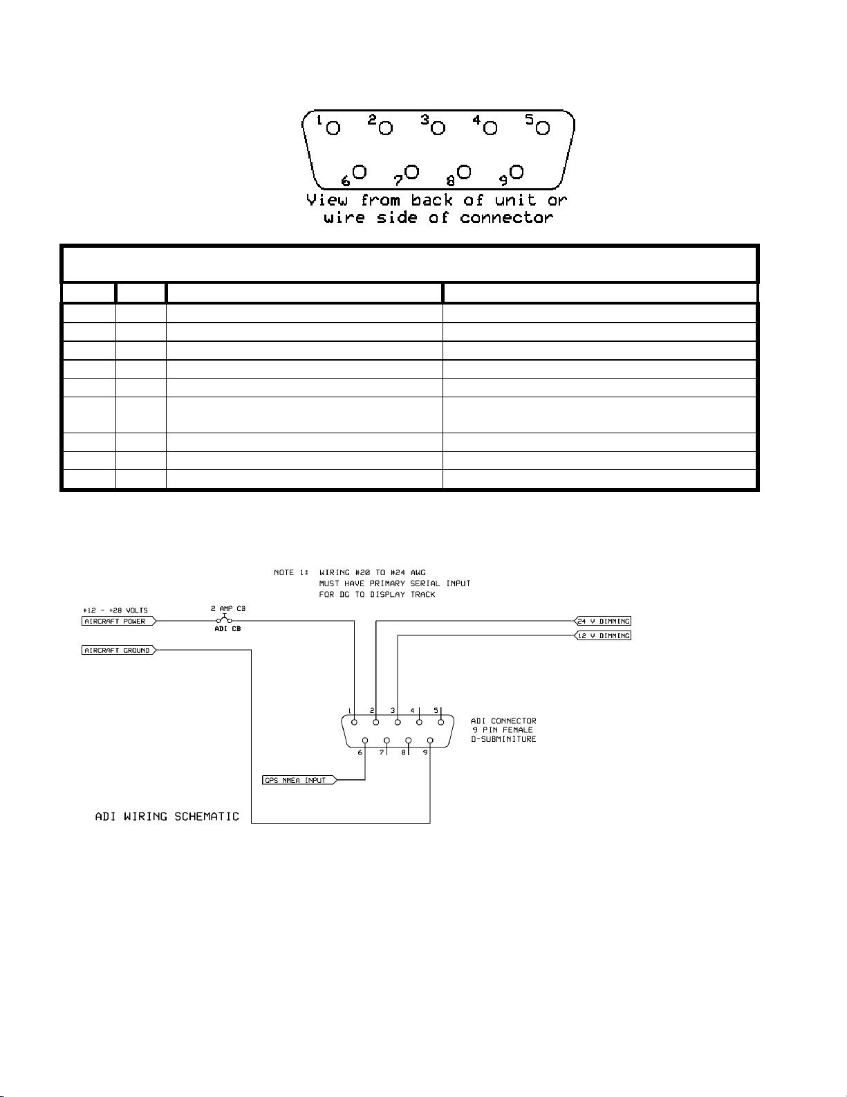
ADI with Battery Backup
ADI Block Diagram
TruTrak Flight System 4 ADI Flight Instrument Installation Manual
December 2009 8300-016 Rev B
Page 7

ADI Backup Battery Block Connection
ADI Backup Battery PIN OUT
TruTrak Flight System 5 ADI Flight Instrument Installation Manual
December 2009 8300-016 Rev B
Page 8

GPS Setup Guide
Many new handheld GPS’s have adequate output required to fly a TruTrak autopilot. Although most support data output
not all handhelds will provide consistent and reliable information required to fly all TruTrak autopilots. Therefore, some handhelds
will not fly the airplane well. Performance may decline by putting the processor in high-load situations.
We require a data output rate of once per second for best performance. Some handhelds output data at longer intervals than
once per second. These handhelds will cause the autopilot not to perform well in turns and it may cause overshooting and hunting.
If the baud rate is selectable the optimum setting is 4800. Most handhelds will require a data cable that plugs into the handheld and
provides a medium for data output. This is an accessory and is available from your GPS manufacturer. The setup procedures are in
your GPS manual. If your GPS is not listed here consult your GPS manual for NMEA output setup. The autopilot must have a
direct connection with the handheld GPS to provide the autopilot with RS-232. To allow the handheld GPS to be removed easily
you should add a connector in your panel. We recommend that you use a 9 pin D subminature connector in your panel that will
mate to the harness from the GPS. This will also allow you to wire power and ground and use the aircraft electrical system to power
your handheld GPS.
Magellan GPS 315 A
The Magellan GPS 315 A requires a Power/Data Cable (Magellan Product Number 730276) to provide data output.
The Magellan GPS 315 A must be configured to provide the correct output to the autopilot.
Press the MENU key then select “Setup. Press ENTER. Select “NMEA” and press ENTER. Select “V2.1 GSA” then
press ENTER. Next we must set the baud rate. Press MENU then select “SETUP” and press ENTER. Next Select
“BAUD RATE” and press enter. Select 4800 for the baud rate. Press ENTER.
Note that this is the baud rate that will be entered into the autopilot in the setup mode.
Garmin GPS III
The Garmin III requires a Power/data cable (Garmin Part Number 010-10082-00) to provide data output.
The Garmin III must be configured to provide the correct output to the autopilot.
Press the MENU key twice. Select ‘Setup’. Press ENTER. Select the ‘Interface’ tab. Press ENTER. Select the NMEA
format.
Note: The default baud rate is 4800. This is the baud rate that will be entered into the autopilot in the setup mode.
GPS 92
The Garmin 92 requires a Power/data cable (Garmin Part Number 010-10082-00) to provide data output. The Garmin 92 must be
configured to provide the correct output to the autopilot.
Press the PAGE key until the ‘Main Menu’ appears. Select ‘Setup Menu’ and press ENTER. Next select ‘Interface.’
Press ENTER. Select NONE/NMEA.
Note: The default baud rate is 4800. This is the baud rate that will be entered into the autopilot in the setup mode.
Garmin GPS 195
The GPS 195 provides data output every two seconds and may be slow in recognizing turns and will overshoot the desired track.
This may cause the autopilot to wander and not perform well in turns.
The Garmin 195 requires a Power/data cable (Garmin Part Number 010-10135-00) to provide data output. The Garmin 195 must be
configured to provide the correct output to the autopilot.
Press the MENU key twice. Select ‘Set-Up Menu’. Press ENTER. Select ‘Input/Output’. Press ENTER. The
input/output format is ‘No In/NMEA Out.’ Note that the baud rate is automatically set at 4800 bps.
Note: This is the baud rate that will need to be entered in the setup mode of the autopilot.
Now the Garmin 195 is correctly set up to provide the RS-232 serial output required by your TruTrak autopilot.
TruTrak Flight System 6 ADI Flight Instrument Installation Manual
December 2009 8300-016 Rev B
Page 9

Garmin GPS 196
The Garmin 196 requires a Power/data cable (Garmin Part Number 010-10082-00) to provide data output.
The Garmin 196 must be configured to provide the correct output to the autopilot.
Press the MENU key twice. Use the arrow keypad to select the ‘SETUP’ tab.
Within the Setup Menu select the ‘INTERFACE’ tab. Using the arrow keypad highlight the ‘Serial Data Format’ field.
Use the arrow keypad to select ‘NMEA In/NMEA Out’ and press ENTER.
Set the baud rate to 4800.
Note: This is the baud rate that will need to be entered in the setup mode of the autopilot.
Press MENU to enter the Advanced NMEA page. Select ‘Advanced NMEA Setup’ and press ENTER.
Using the arrow keypad and the ENTER key to turn OFF ‘GPS Status (GSA, GSV)’, ‘Waypoint/Route (WPL, RTE)’, and
‘GARMIN Proprietary’.
Now the Garmin 196 is correctly set up to provide the RS-232 serial output required by your TruTrak autopilot.
Garmin 295
The Garmin 295 requires a power/data cable (Garmin Part Number 010-10082-00) to provide data output. The Garmin 295 must be
configured to provide the correct output to the autopilot.
Press the MENU key twice. Use the rocker keypad to select the ‘INTERFACE’ tab.
Press the down portion of the rocker keypad to select the ‘FORMAT’ field.
Press ENTER and a popup window will show the available settings.
Use the rocker keypad to select ‘NMEA OUT’ then press ENTER. Select 4800 for the baud rate.
Note: This is the baud rate that will need to be entered in the setup mode of the autopilot.
Now the Garmin 295 is correctly set up to provide the RS-232 serial output required by your TruTrak autopilot.
Garmin 296
The Garmin 296 must be configured to provide the correct output to the autopilot.
Press the MENU key twice. Use the rocker keypad to select the SETUP in the vertical tabs. Use the rocker keypad to
select the ‘COM 1’ tab.
Press the down portion of the rocker keypad to select the ‘FORMAT’ field.
Press ENTER and a popup window will show the available settings.
Use the rocker keypad to select ‘NMEA IN / NMEA OUT’ then press EN TER. Select 4800 for the baud rate. Note: This
is the baud rate that will need to be entered in the setup mode of the autopilot.
Press MENU to enter the Advanced NMEA page. Select ‘Advanced NMEA Setup’ and press ENTER.
Using the arrow keypad and the ENTER key to select “FAST OUTPUT” or turn OFF ‘GPS Status (GSA, GSV)’,
‘Waypoint/Route (WPL, RTE)’, and ‘GARMIN Proprietary’.
Now the Garmin 296 is correctly set up to provide the RS-232 serial output required by your TruTrak autopilot.
Garmin 396
The Garmin 396 must be configured to provide the correct output to the autopilot.
Press the MENU key twice. Use the rocker keypad to select the SETUP in the vertical tabs. Use the rocker keypad to
select the ‘Interface’ tab.
Press the down portion of the rocker keypad to select the ‘Serial Data Format’ field.
Press ENTER and a popup window will show the available settings.
Use the rocker keypad to select ‘NMEA IN / NMEA OUT’ then press EN TER. Select 4800 for the baud rate. Note: This
is the baud rate that will need to be entered in the setup mode of the autopilot.
Press MENU to enter the Advanced NMEA page. Select ‘Advanced NMEA Setup’ and press ENTER.
Using the arrow keypad and the ENTER key to select “FAST OUTPUT” or turn OFF ‘GPS Status (GSA, GSV)’,
‘Waypoint/Route (WPL, RTE)’, and ‘GARMIN Proprietary’.
Now the Garmin 396 is correctly set up to provide the RS-232 serial output required by your TruTrak autopilot.
TruTrak Flight System 7 ADI Flight Instrument Installation Manual
December 2009 8300-016 Rev B
Page 10

Garmin 496
The Garmin 496 must be configured to provide the correct output to the autopilot.
Press the MENU key twice. Use the rocker keypad to select the SETUP in the vertical tabs. Use the rocker keypad to
select the ‘Interface’ tab.
Press the down portion of the rocker keypad to select the ‘Serial Data Format’ field.
Press ENTER and a popup window will show the available settings.
Use the rocker keypad to select ‘NMEA IN / NMEA OUT’ then press EN TER. Select 4800 for the baud rate. Note: This
is the baud rate that will need to be entered in the setup mode of the autopilot.
Press MENU to enter the Advanced NMEA page. Select ‘Advanced NMEA Setup’ and press ENTER.
Using the arrow keypad and the ENTER key to select “FAST OUTPUT” or turn OFF ‘GPS Status (GSA, GSV)’,
‘Waypoint/Route (WPL, RTE)’, and ‘GARMIN Proprietary’.
Now the Garmin 496 is correctly set up to provide the RS-232 serial output required by your TruTrak autopilot.
Lowrance Airmap 100
The Lowrance Airmap 100 requires a NMEA/DGPS adapter cable to provide data output. The Lowrance Airmap 100 must be
configured to provide the correct output to the autopilot.
Press the MENU key then select “NMEA/DGPS CONFIG” from the “System Setup” menu. Highlight the “NMEA OUT”
menu then press the right arrow key.
Note: The default baud rate is 4800. This is the baud rate that will entered into the autopilot in the setup mode.
Now the Lowrance Airmap 100 is correctly set up to provide the RS-232 serial output required by your TruTrak autopilot.
Lowrance Airmap 1000/2000
The Lowrance Airmap 1000/2000 requires a NMEA/DGPS adapter cable to provide data output. The Lowrance Airmap 1000/2000
must be configured to provide the correct output to the autopilot. AirMap has one NMEA 0183 version 2.0 compatible
communication port,
Press MENU|MENU|↓ to SYSTEM SETUP|ENT. Press ↓ to COMMUNICATIONS PORT|ENT. Select 9600 Baud.
This is the baud rate that will entered into the autopilot in the setup mode. Select “NMEA OUT”
Now the Lowrance Airmap 1000/2000 is correctly set up to provide the RS-232 serial output required by your TruTrak autopilot.
AvMap EKP IV
The AvMap EKP IV requires a NMEA/DGPS adapter cable to provide data output. The AvMap EKP IV must be configured to
provide the correct output to the autopilot.
MENU’ 1 sec. + “COMMUNICATIONS” + ‘ENTER’ + “NMEA OUTPUT” + ‘ENTER’.
The Output NMEA0183 messages are RMC, RMB that need to be selected.
Note: The default baud rate is 4800. This is the baud rate that will entered into the autopilot in the setup mode. The yellow wire is
the Data out TX wire.
Now the AvMap EKP IV is correctly set up to provide the RS-232 serial output required by your TruTrak autopilot.
Garmin 35-HVS
Connect Red to Power and Black to Ground then White to Serial input.
The default baud rate is 4800. This is the baud rate that will entered into the autopilot in the setup mode.
There is no necessary setup procedure for the Garmin-35 unit. It may require up to 45 minutes to achieve a position fix the first time
it is powered on; afterwards it will take less time to obtain a position fix as it contains its own battery and position memory. To use
this unit, configure the DigiFlight II’s baud rate to 4800 baud in the setup screen. This unit does not provide GPS-NAV
information, course guidance, or flight planning. Its sole function is to provide the autopilot with a source of ground track and
ground speed information to slave the autopilot’s internal DG function.
TruTrak Flight System 8 ADI Flight Instrument Installation Manual
December 2009 8300-016 Rev B
Page 11

Garmin 155XL/250XL/300XL
Garmin 155XL/250XL/300XL connections to TruTrak autopilot
J1 on
Garmin unit
24 GPS RS 232 OUT 2 Primary Serial Input 6
Press and hold the MSG key and rotate the outer knob until the I/O setup page is displayed. Press CRSR twice and rotate inner knob
to select “plotting”. Rotate the outer knob to advance to the baud rate field. Use the inner knob and set to 9600. Press the CRSR to
finish and save
Note that for the Garmin units, the autopilot will need to be set for 9600 baud.
Garmin 430 and 530
P4001 [P5001] on
Garmin 430 [530]
56 GPS RS 232 OUT 1 Primary Serial Input 6/17
46 GPS ARINC 429 OUT A ARINC-A 14
47 GPS ARINC 429 OUT B ARINC-B 15
Signal Name
(Garmin)
Garmin 430 and 530 connections to TruTrak autopilot
Signal Name
(Garmin)
Signal Name
(TruTrak)
Signal Name
(TruTrak)
ADI
P101 on
TruTrak ADI/DII
Power 430/530 up and turn it on while holding down the ENT key. Release the ENT key when the display activates. After the data
base pages, the first page displayed is the MAIN ARINC 429 CONFIG page. While in Configuration mode, pages can be selected
by ensuring the cursor is off and rotating the small right knob. To change data on the displayed Configuration Page, press the small
right knob (CRSR) to turn on the cursor. Turn the large right knob to change between data fields. Turn the large or small right knob
to change a field that the cursor is on. Once you have made the desired selection, press the ENT key to accept the entry.
With the MAIN ARINC 429 CONFIG page displayed, on the row labeled OUT, select SPEED Î Low
and DATA ÎARINC 429.
Advance to the MAIN RS232 CONFIG page.
On the row labeled CHNL1, select OUTPUT Î Aviation.
Note that for the Garmin units, the autopilot will need to be set for 9600 baud.
KMD 150
Power the KMD 150 up and turn it full bright. Press the MENU button then the SETUP button then the INST & DIAGS button then
the DATA IN/OUT. Change the DATA OUT PUT to NEMA 0183 the manual states the Baud rate is 9600. The output pin is pin 11
and connects to the Primary Serial input on the auto pilot controller.
You will need to match 9600 Baud rate in the auto pilot.
KMD 150 connections to TruTrak autopilot
37 Pin Connector
on KMD 150
Signal Name
Signal Name
(TruTrak)
P101 on
TruTrak ADI/ DII /Sorcerer
11
TruTrak Flight System 9 ADI Flight Instrument Installation Manual
December 2009 8300-016 Rev B
(AV NAV)
Primary Serial Input
6/17/25
Page 12

UPSAT GX-50/60/65
UPSAT GX-50/60/65 connections to TruTrak autopilot
37-Pin Connector
on UPSAT
GX-50/60/65
Use pin 5 – TxD1 – if GX has no
Garmin AT GNS480 connections to TruTrak autopilot
P1 on GNS480 Signal Name (Garmin AT) Signal Name
22 RS232 TxD2 Primary Serial Input 17/25
Signal Name
(UPSAT)
GPSS
Signal Name
(TruTrak)
(TruTrak)
P101 on
TruTrak DII
P101 on TruTrak
DII/Sorcerer
P5 on GNS480 Signal Name (Garmin AT) Signal Name
(TruTrak)
4 429 OUT 1A ARINC-A 14/26
24 429 OUT 1B ARINC-B 15/27
Use pin 22 – TxD2 – if GX has
GPSS
Power the GX-50/60/65 up and turn it on while holding down the leftmost and rightmost “smart keys.” Rotate the LARGE knob to
the Serial Interface Configuration “CH RX TX” page. Press SEL (the selection fields will start flashing), rotate the LARGE knob to
select the port, rotate the SMALL knob to select the desired configurations, and then press ENT when complete.
If both the GX unit AND the DigiFlight unit have GPSS capability,
select “GPSS” for CH 2, TX column, and wire pin 17 on the DigiFlight IIVSG to pin 22 of the GX unit
Otherwise
select “MOVING MAP” For CH 1, TX column and wire pin 17 on the DigiFlight II / IIVS to pin 5 of the GX unit
To restore the GX-50/60/65 to normal operation, switch its power off, and then back on.
Note that for the GX-50/60/65 units, the autopilot will need to be set for 9600 baud.
P101 on TruTrak
DII/Sorcerer
Garmin AT GNS480
Power 480 up and select the 1, 4, MENU/ ENTER keys immediately after the GNS 480 initialization is complete. After restart, the
first page displayed is the SETUP page. Select the SERIAL PORTS with the button next to it. Press the small knob to enter the edit
mode and move to the TX column for the channel that you have connected the serial wire to (channel 2). Select MAPCOM and
9600. Press the small inner knob again to save. Then press the BACK to go back to the Setup page.
Select the ARINC PORTS SETUP. With the MAIN ARINC 429 CONFIG page displayed, on the row labeled Channel 1 OUT,
select and DATA ÎARINC 429, SPEED Î Low.
Serial output baud rate should be set to 9600 on the GNS480. Set the TruTrak baud rate to 9600.
TruTrak Flight System 10 ADI Flight Instrument Installation Manual
December 2009 8300-016 Rev B
Page 13

Trouble Shooting Guide
PROBLEM POSSIBLE CAUSE CORRECTION
ADI will not function No aircraft voltage to pin 1 or
No aircraft ground on pin 9
DG does not display No RS 232 on pin 6 (GPS input)
No ground return from GPS
On power up ADI rolls off to
side
Air Speed warning
Insufficient voltage or current to
ADI
No Pitot connection Connect Pitot line to Pitot port
Correct wiring problem
Confirm battery voltage
Connect pin 6 to GPS source &
configure output to NMEA
Install ground from GPS unit
Confirm aircraft voltage(Min +11v)
Correct bad wires (low current)
nonfunctional
Internal GPS nonfunctional GPS did not find satellites
Unable to find satellites
Wrong wire at pin 6 (GPS output)
Display always flashes with
Incorrect wiring on pin 2 or 3 Correct wiring to dimmer
Wait for center bar to stop flashing
Relocate antenna to better position
Correct wiring at pin 6 (GPS output)
GPS on
TruTrak Flight System 11 ADI Flight Instrument Installation Manual
December 2009 8300-016 Rev B
Page 14

Warranty On TruTrak Flight Systems Products
We here at TruTrak Flight Systems know how important it is to feel as though the customer is purchasing a product that
the manufacturer is going to stand behind. For this reason we want offer more than the basic one year warranty that is
standard to this industry. The warranty on all TruTrak products will be three years from the date of purchase. Abuse
and misuse of a product are not covered under this warranty. Modification to a product may void the warranty, as well as
carry a penalty when upgrading to another product. This three year warranty will be for all products except the Pictorial
Turn & Bank, which will continue to have a warranty of one year from the date of purchase.
TruTrak Flight Systems No Penalty Upgrade Policy
As the product line continues to grow, it becomes increasingly difficult to maintain a simple upgrade policy. We do want
to reward our repeat customers by allowing a lower cost upgrade from one system to another; however we are not able
to offer this across the board on all products. If you are considering an upgrade, please call and we will give you a
quote on what this would cost. Many products that we sell today are upgradeable for only the difference in system
price. Because we continually strive to have the most up to date products possible, we occasionally have to discontinue
products. We will continue to offer discounted upgrades even for our discontinued products.
TruTrak Flight System 12 ADI Flight Instrument Installation Manual
December 2009 8300-016 Rev B
Page 15

RETURN MERCHANDISE POLICY AND PROCEDURE
• Under no circumstances should products be returned to TruTrak without first obtaining a Return of
Merchandise Authorization number (RMA #) from TruTrak. An RMA# may be obtained by contacting us
INTERNATIONAL SHIPMENTS:
at 866-878-8725.
• Products that do not have an RMA # will not be processed.
• Please include documentation stating the reason for the return and describing any symptoms, failure modes,
suspected causes of damage, diagnostics performed, data collected, etc.
• Product(s) should be packaged in their original shipping containers. In lieu of this, they should be very
carefully packaged in containers suitable to protect them during transit. For your protection, items should
be insured for the full value. Note that damage caused during shipping will not be repaired under warranty.
• The outside of the box must be clearly marked with the RMA # issued by TruTrak and the RMA # must
also be noted on the return documents.
• Products will be returned to the customer at no charge via FedEx Ground or UPS Ground. If customer
requests expedited shipping (2
nd
Day or Overnight) they will be charged the shipping cost and must supply
a credit card number.
• Trutrak sends all International shipments with an insurance value on all products. Trutrak pays for shipping
only. The customer is responsible for any and all additional fees, duties, taxes associated with the
shipment.
• When sending products to Trutrak for repair or otherwise please be advised that the customer is responsible
for all charges and fees associated with shipment. For your protection, items should be insured for the full
value.
• Trutrak states on all product returns “WARRANTY REPAIR AT NO CHARGE TO CUSTOMER. A
COMMERCIAL INVOICE VALUE OF $___ GIVEN FOR INSURANCE PURPOSES ONLY”
Please keep in mind that your government or another entity in your country may impose a charge for custom and/or
brokerage fees, duties and taxes on items received from the US. These charges do not originate from our company nor do
we benefit from them in any way. You are responsible for payment of all custom and brokerage fees, duties and taxes that
may be imposed when these goods are imported into your country.
• Send ALL return shipments to:
Trutrak Flight Systems, Inc., 1500 South Old Missouri Road, Springdale, AR 72764 USA
Attention: Returns Dept. RMA# ______________
Page 16

TRUTRAK FLIGHT SYSTEMS
1500 S. Old Missouri Road
Springdale, AR 72764
Ph: 479-751-0250 Fax: 479-751-3397
Toll free: 866-TRUTRAK
866-(878-8725)
www.trutrakap.com
 Loading...