

Page 1
EMS BU / EDM
Installation & Operation Manual
8300-065 Rev D
TRUTRAK FLIGHT SYSTEMS
1500 S. Old Missouri Road
Springdale, AR 72764
Ph. 479-751-0250 Fax 479-751-3397
www.trutra
kflightsystems.com
Page 2

INSTALLATION MANUAL
TABLE OF CONTENTS
MECHANICAL INSTALLATION....................................................................................1
PITOT AND STATIC CONNECTIONS...........................................................................1
RFI/EMI .............................................................................................................................1
OPERATING CONTROLS................................................................................................2
SETUP SCREENS .............................................................................................................4
UNITS................................................................................................................................4
CONFIG.............................................................................................................................5
GAUGES ............................................................................................................................6
SWITCHES........................................................................................................................7
GAUGES ............................................................................................................................7
CALIB................................................................................................................................7
SNSRS................................................................................................................................8
EFIS SOFTWARE UPDATES...........................................................................................9
SENSORS AND INPUTS..................................................................................................9
EMS ELECTRICAL PIN-OUT........................................................................................15
EMS / EDM BASIC WIRING DIAGRAM......................................................................17
EVEKTOR WIRING DIAGRAM....................................................................................20
EDM ELECTRICAL PIN-OUT.......................................................................................21
ROTAX WIRING DIAGRAM.........................................................................................21
EFIS AP / EMS / EDM BLOCK DIAGRAM..................................................................22
NINE CYLINDER EDM BLOCK DIAGRAM...............................................................23
RETURN MERCHANDISE POLICY AND PROCEDURE...........................................29
FOR
EMS / EDM
Revision Date Description Page #
A 1/1/2009 Initial Release
B 03/23/09 Schematic corrections 15, 18, 19
C 04/14/2009 Updated installation & display options ALL
D 06/16/2009 Added nine cylinder option 6, 18, 19, 23, 24
Page 3
Mechanical Installation Considerations
PROGRAMMER INSTALLATION
Mounting Considerations
The EMS Series unit is designed to mount in the aircraft instrument panel within view and reach of the
pilot. The primary unit location should minimize pilot head movement when transitioning between
looking outside of the cockpit and viewing/operating the EMS Series unit. Maximum recommended
viewing angle should be no more than 20 deg. The maximum mounting angle the EMS can accommodate
is 12 degrees longitudinal axis and 0 degrees lateral axis. The location should be such that the EMS Series
unit is not blocked by the glare shield on top, or by the throttles, control yoke, etc. on the bottom. Use
aircraft installation standards for mounting and support of the EMS programmer.
EDM should be mounted on the firewall so that both sides can be accessed for service. Do not run
wire along fuel lines for support. All wiring should be mounted above fuel and hydraulic line for safety.
Never mount wiring directly on support structures, use Adel clamps or wire stand-offs.
Wiring Considerations
Use AWG #24 or larger wire for all connections in the interior of the aircraft unless otherwise specified.
Engine wiring should not be smaller than AWG #22. The standard crimp pin contacts supplied in the
connector kit are compatible with up to AWG #20 wire. In cases where some installations have more than
one component sharing a common circuit breaker, sizing and wire gauge is based on length of wiring and
current draw on units. In these cases, a larger gauge wire such as AWG #20 may be needed for power
connections. Do not attach any wires to the outside of the EMS or route high current wires within six (6)
inches of the programmer. Ensure that routing of the wiring is not exposed to sources of heat, RF or EMI
interference. Check that there is ample space for the cabling and mating connectors. Avoid sharp bends in
cabling and routing near aircraft control cables. Do not route the COM antenna coax near any EMS
components.
RFI/EMI considerations
The EMS programmer is shielded and does not generate any appreciable level of electromagnetic
interference. The EMS itself has been internally protected from RF interference and has been tested
under fairly extreme conditions, such as close proximity to
transmitting antennas. However, it is always good practice
to insure that such antennas are properly shielded and not
routed directly over or under sensitive panel-mounted
electronic equipment. Most problems in this area are the
result of improper RF shielding on transmitting antennas,
microphone cables, and the like.
Pitot and Static Connections
The TruTrak EMS requires connections to the Pitot and
static lines. The preferred m
ethod of this connection would
be tee fittings near the aircraft’s airspeed indicator.
PITOT STATIC
TruTrak Flight Systems 1 EMS Installation Manual
JUNE 2009 8300-065 Rev D
Page 4
Operating controls
As with our autopilot products, extensive attention has been given to providing the simplest operation.
No sequential pressing of buttons is required to reach basic control functions. Active descriptions of Knob
or Button functions are labeled on display above. If there is a second EFIS connected by way of the TCBA & B wires, information will be communicated between the two units.
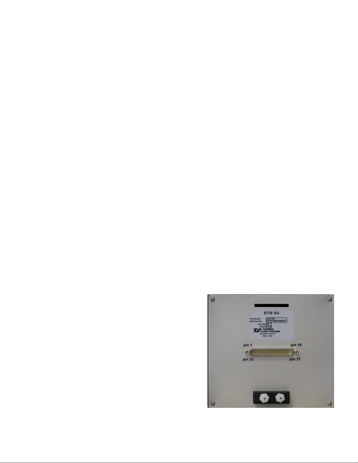
BARO Selection (Backup Gauges only)
In the TruTrak EMS display, barometer BARO is
set by rotation of the right dedicated knob. The
Baro reading is displayed in the Altimeter. The
yellow band along with the numerical VS
displayed above indicates VSI direction and speed.
GPS Information
The T&B DG requires GPS NMEA information to
function correctly. If the primary serial connection
and communication protocols have been setup
correctly, the EMS T&B gauge will display the
DG. Also, the timer is updated with GPS NMEA
information.
Dimming
Dimming of the display is accomplished by rotating the left knob, DIM rotating the knob Counter Clock
Wise to reduce the display illumination. External dimmer input will control the button illumination.
MAIN Page
MAIN page display are shown to the right top of
page picture showing Back Up instrument and the
picture to the right without Back Up.
TruTrak Flight Systems 2 EMS Installation Manual
JUNE 2009 8300-065 Rev D
Page 5
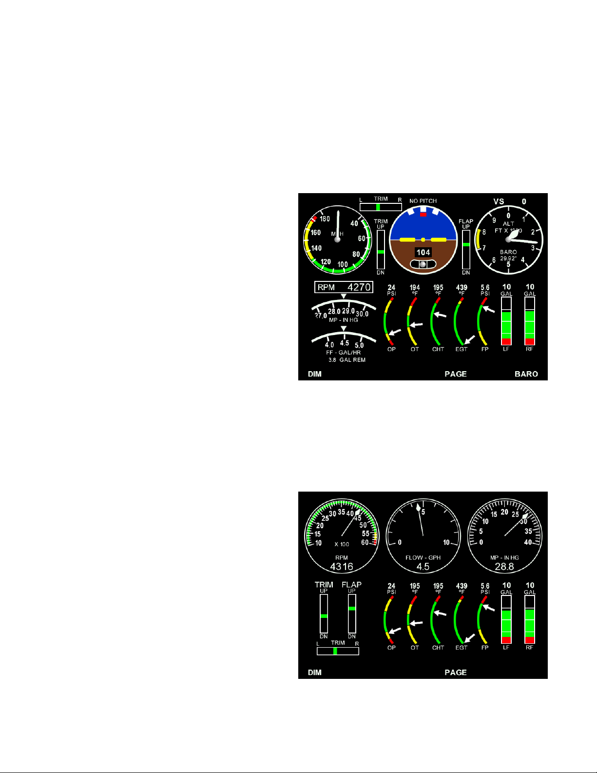
CHT /EGT Page
This page displays a detailed readout of all the CHT and EGT
sensors. Also, PEAK readings will be marked on this page. The
highest reading will be the CHT and EGT that is displayed on
the MAIN page.
TIMER Page
This page displays all the timers that are tracked. Detailed fuel
information and contact switch position along with voltage and
amp indications if installed.
The TIMER Page will be displayed on power up so that fuel
information can be updated. Also, the trip and leg timers can be
reset if needed.
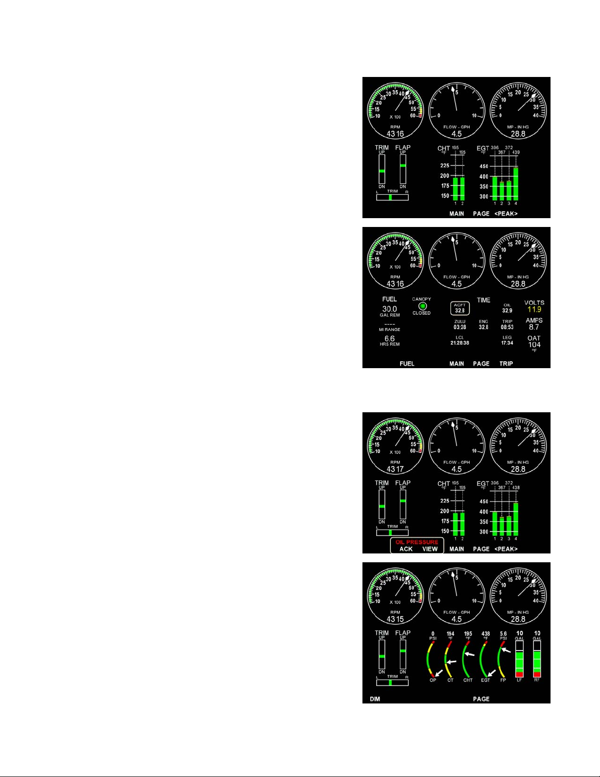
Any parameter that enters a yellow ARC will change the reading displayed to yellow. See VOLTS. If the
parameter progresses to the red position the EMS / EFIS will display a warning box at the bottom of the
screen.
WARNINGS
There will be a warning box that will be displayed at the bottom
of the screen when a parameter first enters the red arc.
See OIL PRESSURE.
Pressing the button below ACK will remove the warning box
and the button below VIEW will change the page to the detailed
view page if different than the current page.
bottom picture oil pressure indication.
See
TruTrak Flight Systems 3 EMS Installation Manual
JUNE 2009 8300-065 Rev D
Page 6
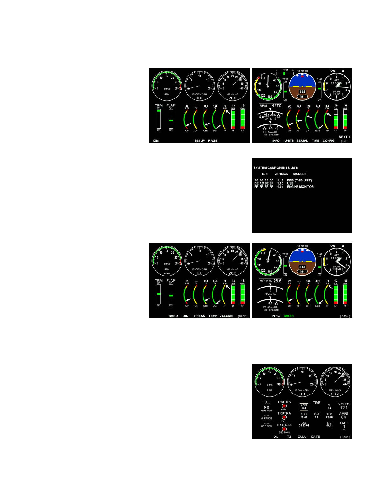
SETUP SCREENS
INFO, UNITS, TIME, CONFIG, GAUGES, CALIB
To enter the setup screen the right
knob must be pressed and held until
the SETUP shows then press and
release the button below SETUP
before releasing the right knob.
Rotate the right knob to step to the
next page.
Press and release the right knob
[EXIT] to step back a page or to
return to the main screens.
INFO
Displays serial numbers and software version and model type of all
units connected to the TruTrak communication wires (TCB-A, TCBB).
Exit by press and release of left knob.
UNITS
BARO, IN HG or MBAR
DIST, NM, MI or KM
PRESS, PSI, IN HG or KPA
MANIFLD, IN HG or MMHG
TEMP, F or C
VOLUME, GALLON or LITER
These pages will allow the setting of
UNITS of Measure for the different
display readouts listed.
Example: Press and release BARO to select IN HG or MBAR as shown.
TIME
OIL, TZ, ZULU, DATE
Pressing the OIL button will reset the OIL, TRIP, & LEG timers.
LEG timer will reset with zero oil pressure for @ 5 min.
TRIP is reset with button.
The TZ (time zone) button sets your time zone by +/- from GMT
(Standard Central TZ = -6).
Set ZULU time with this button.(GMT)
Set the DATE with this button. The next screen allows the selection
of MONTH, DAY, and YEAR. Rotate the right knob to change
setting.
TruTrak Flight Systems 4 EMS Installation Manual
JUNE 2009 8300-065 Rev D
Page 7
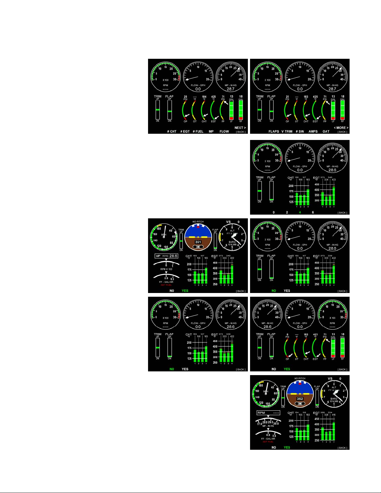
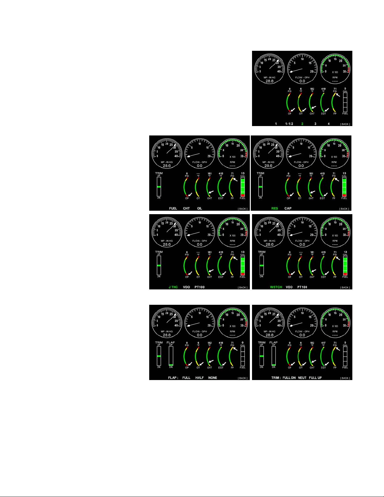
CONFIG
#CHT, #EGT, #FUEL, MP, FLOW, FLAPS, V TRIM, H TRIM, #SW, AMPS, OAT, CARB, BKUP,
COMPLX.
These pages will allow the selection
of the different type and quantity of
indicators displayed. Select the
sensors that are installed and the
quantity as needed.
Example: Press and release # CHT to select number of CHT
probes installed, 4 as shown to the right.
BKUP displays the engine
instrument with Airspeed, T&B,
Altimeter/VSI in upper part of
display. (right)
The far right picture is shown
without BKUP selected
As shown on the right pictures, the
COMPLX engine dial instruments
will move the MP to the left side.
COMPLX will also switch the MP to a more detailed display in the
BKUP mode. RPM (digital)and MP (analog display) swap for more
detailed information.
TruTrak Flight Systems 5 EMS Installation Manual
JUNE 2009 8300-065 Rev D
Page 8
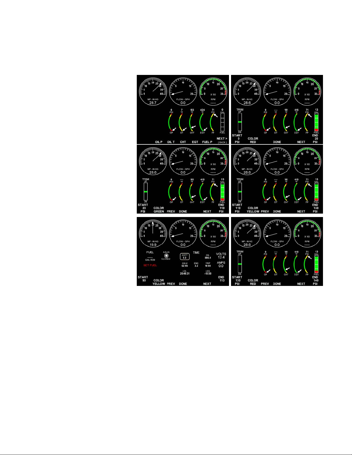
GAUGES (ARC COLOR BAND SETTING)
OIL P, OIL T, CHT, EGT, FUEL P, TANK1, TANK2, RPM, FFLOW, MP, VOLTS, SW #1-3
These pages allow the different colored arcs to be set for the gauge selected. Also, changing Switch
labeling and color. Some gauge arcs are preset at factory.
Select the type gauge to adjust (OIL
P), (upper right picture) the left knob
sets the START position or the
bottom color setting for that part of
the arc, adjust as needed.
Pressing the button below the
COLOR will step through the
available colors for that section of
arc.
The right side knob will adjust the
END or top setting for this arc color.
Adjust as needed.
Press and release NEXT.
Set the next color in the arc (left
middle). Step through all the setting
for all the arc colors, adjust as
needed. Press and release DONE
when finished. Oil Pressure is
shown from 0 to 140 PSI with four
(4) colors in the arc.
NOTE: VOLTS ARC numbers are
1 volt = 10 digit. Exp. 12V = 120
Pressing PREV or NEXT will step
to the previous or next screen as needed to correct or set.
NINE CYLINDER EDM
To have a nine (9) cylinder EDM system the EDM must be setup using the PC TruTrak software.
With a nine (9) cylinder system pin 29 (Contact #1) of the 37 pin DB connector (J1) MUST be grounded to show
cylinder # 7, 8, 9. When the switch is open the EMS display will show CHT/EGT #1-6. When the switch is closed the
display will show CHT/EGT 7-9 in place of 1-3. #4,5,6 will NOT be reported
#1 on the third display page.
FOR AIR PRESSURE OPERATION
The EDM is designed to use a 0-1000 PSI sensor that has a 4-20 ma output. This sensor output must be connected to
pin 32 on the 37 pin DB (J1) connector. Sensor power can be connected to pin 31 if aircraft voltage.
Currently, Air pressure will be displayed under the CARB temp Heading. The display will read in degrees F, BUT, in
actuality it will be in PSI. If the UNITS are changed to Celsius the air pressure will be wrong, the display MUST be in
Fahrenheit.
Unless there is access to the TruTrak setup programming software from the PC, the user MUST NOT change the
CARB, TACH, EGT#, CHT# settings. Doing so will result in the unit not functioning properly.
TruTrak Flight Systems 6 EMS Installation Manual
JUNE 2009 8300-065 Rev D
. This will also change the state of Contact
Page 9
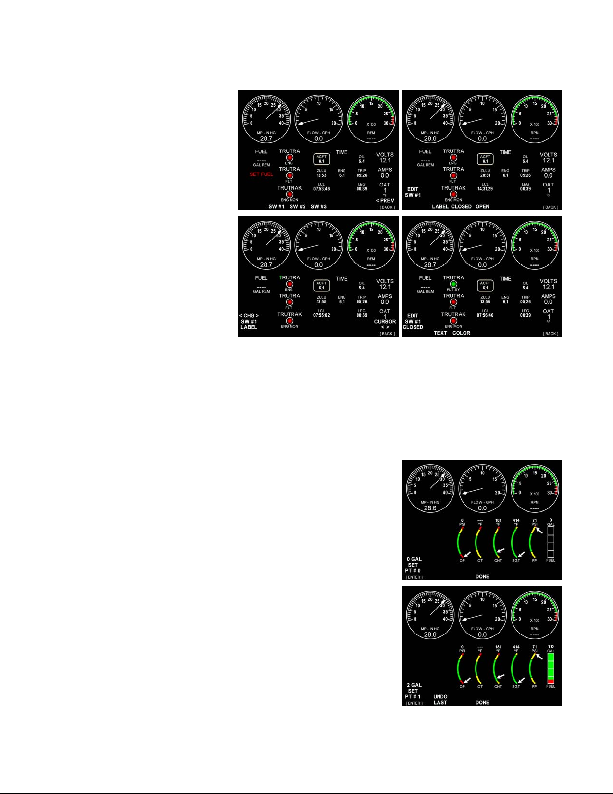
SWITCHES (CONTACTS)
Select the switch (SW # 1) to change
the label on. Select LABEL, now
the left knob will select the
alphanumerical digits and the right
knob will move the cursor position
(green). Select the name for this
switch, there are seven (7) digits
available. Press and release the right
knob (back) to return to the last
page. Select OPEN or CLOSED,
select TEXT to change the label
displayed when the contact is open
or closed. Select COLOR to change
the color that is displayed in ether
switch position.
Press and release the right knob
(back) repeatedly to return to the
beginning.
CALIBRATION
FUEL, TACH, SNSRS, FLAPS, TRIM, SPEEDS, & BALL
These pages allow the selection and calibration of the Fuel level, Tach, Sensors, Flaps and Trim
indicators. Also to set the Baud rate and center the ball in the T&B after installation.
FUEL
The type of and # of fuel sensors MUST be selected first (see CONFIG & SNSRS).
Calibration of tank / guages, there are a total of 15 PTs (calibration
points) possible, not all are necessary.
Select the tank to calibrate, with the tank empty, the first PT #0 is 0
GAL, press [enter]. Add fuel, in whole gallons until the number of
GAL over the displayed gauge just starts to move. Wait until the
number stabalizes. Enter the gallons added by rotating the left knob
and press [enter], PT #1. The gauge colors and number of GAL are not
correct until the calibration are complete. Continue adding fuel, each
PT# should have the total amount of fuel in the tank at that time and
wait until the number stabalizes. When the number displayed STOPS
changing when adding fuel, STOP. This is the last PT # even if the
tank is not full, enter the total gallons in the tank by rotating the left
knob, wait until the number stabalizes. Press DONE.
The sender can not measure fuel past this point. This is NOT to total
fuel used in calcuating remaning fuel. Only the @ amount of fuel in
the tanks.
TruTrak Flight Systems 7 EMS Installation Manual
JUNE 2009 8300-065 Rev D
Page 10
TACH
Select the pulses per revolution,
Lycoming 4 cyclinder = 2
Rotax = 1
SNSRS
FUEL, CHT, OIL;
FUEL Select the type of sender,
Resistive or Capacitance
CHT Select type of Sensor, J type
(J THC), Resistive (VDO), PT100
OIL Select type of Sensor,
Honeywell (WSTCH), Resistive
(VDO), PT100
FLAPS and TRIM
Select the gauge to calibrate,
exp: FLAP, move the flap to full up
and press and release the button
labeled NONE. Continue to HALF
and FULL down positions, pressing
the button for each.
SPEEDS
Select the Baud rate for your GPS input, 9600 or 4800.
BALL (SLIP)
Center the BALL in the T&B after EFIS installation.
TruTrak Flight Systems 8 EMS Installation Manual
JUNE 2009 8300-065 Rev D
Page 11

EMS Software Updates
The EMS software can be updated by inserting a Compact Flash card (CF), with software acquired from
TruTrak Flight Systems. The CF card must be face down, in the top slot on the back. Then apply power
to the EMS, monitor the screen. Follow the instructions on the screen. When power is reapplied to the
EMS the new software version will be installed and displayed at the bottom of the screen.
SENSORS AND INPUTS
TruTrak Fight Systems can provide engine kits for all known engine types when an EMS / EDM order is
placed. The kit provides for all sensors / harnesses /pins needed.
All sensors ordered from TruTrak Flight Systems have a twisted, color coded, harness attached with
correct connections to the sensor. The EDM pin of the harness is not installed to provide easier routing of
the harness. Wires routed on the engine should be routed away from the exhaust system and above fuel
and hydraulic lines per standard aircraft wiring procedures, AC 43. See the installation manual from the
engine manufacture if possible. Engine wiring harnesses route better together where possible and should
be supported on the engine every 6 inches, Adel clamps work best for this, and tied together every 3
inches. All wire on the engine side of the firewall should be 22 gauge (bundle only) or larger with high
temperature insulation (Teflon) . Any connection from the engine to the firewall should have a service
loop to accommodate the movement of the engine.
TACH wires produce a lot of RF and should be shielded to reduce this as much as possible, only ground
one end. This is NOT the MAG wire, that uses the shield as part of the grounding system.
USE PIN OUT PAGES 18 & 19 FOR WIRING REFERENCES
Color codes:
RED------------------------12V (to EDM)
ORANGE-------------------5V (to EDM)
WHITE--------------SENSOR (to EDM)
BLACK------------ GROUND (to EDM)
Cylinder Head Temperature (J TYPE CHT) Probes (8250-036)
Lycoming / Continental engines use the bayonet J type CHT probes.
Rotax 912 engines use two resistive CHT probes that are included with the
engine. These probes are preinstalled, but you need to route the wire connections
(8220-019) from them to the EDM.
Oil Temperature Sensor
Lycoming / Continental engines must install the 399S9 resistive type. OT sensor
PN (8250-038). One black wire to ground (J2 pin 11, 12, 13) the other black wire
to J2 pin 18
Rotax 912 engines use one resistive OT probe that is included with the engine.
This probe is preinstalled, but you need to route the wire (8220-019)
TruTrak Flight Systems 9 EMS Installation Manual
JUNE 2009 8300-065 Rev D
connection to the EDM.
Page 12

Tachometer
Connect a shielded pick-off from the Magneto or electronic ignition box, ground the shield at the ignition
source. See installation manual for the installed electronic ignition box.
The Rotax 912 engines have a 5th trigger coil for the purposes of electrically monitoring rev counts. This
trigger coil outputs to a two-wire harness. Connect either of the two wires to ground. Connect the other
wire to the TACH input on the EDM.
Manifold Pressure Sensor HOSE (82509-047)
The pressure port on the manifold pressure sensor input requires 1/8” inner diameter tubing for a secure
fit. You may need to use adapters to convert up to larger inner diameter tubing for your specific engine. It
is recommended that you use clamps at every transition point
Oil Pressure Sensor (8250-032)
Lycoming / Continental engines must install the TruTrak OP sensor supplied.
Note that if you are installing on a Jabiru or Rotax engine, your engine comes with a
pre-installed oil pressure sensor. You will need to replace this sensor with TruTrak
supplied sensor assembly.
Fuel Pressure Sensor (8250-040)
First, mount the fuel pressure sensor to a fixed location using an Adel clamp or other
secure method. The fuel pressure sensor must not be installed directly to the engine due
to potential vibration problems. Next, connect the fuel sensor to the engine using
appropriate hoses and fittings. Its pressure port has a 1/8-27 NPT pipe thread fitting;
you may need adapters to connect to the pressure port on your engine. Locate the
correct fuel pressure port for your engine. This port must have a pressure fitting with a
restrictor hole in it. This restrictor hole ensures that, in the event of a sensor failure,
fuel leakage rate is minimized, allowing time for an emergency landing.
Carbureted engines: Use the supplied sensor and harness.
WARNINGS:
Due to vibration issues, never connect the sensor directly to engine.
TruTrak Flight Systems 10 EMS Installation Manual
JUNE 2009 8300-065 Rev D
Page 13

Fuel Flow Sensor (8250-041)
The FloScan fuel flow transducer has ¼” female NPT threads at both
the inlet and outlet. Only use ¼” NPT fittings to match. When
installing, do not screw fittings more than two full turns past hand
tightened. The torque should not exceed 180 inch-lbs.
WARNINGS:
Due to vibration issues, never connect the sensor directly to engine.
Do NOT use Teflon tape when screwing in any of the fittings.
Make note of the K factor number on the tag attached to the fuel flow sensor. You will need it in the Fuel
Flow Configuration section. Do not lose this number, the fuel flow calibration will not be correct without
this setting.
Setting K factor:
Press and hold the right knob, wait for “SETUP” to show in center lower display press button below at the
same time you are holding the knob. Press and release “CONFIG” press and release “FLOW”, then
“YES”, set K factor by rotating right knob. Press and rotate to step in 100 increments.
General Placement Recommendations
When placing the sensor, ensure that the three wire leads are pointed straight up. Ensure that the
transducer has 6” of straight fuel line before and after it. Placement of the fuel flow sender relative to
other items in the fuel system like fuel pumps is left to the builder. The manufacturer of the fuel flow
sender does not make strong recommendations on this point. It is not uncommon, though, to place the
sender downstream of any auxiliary electric boost pumps but upstream of the engine driven fuel pump.
For best measuring performance, the fuel should travel uphill by one to two inches after leaving the fuel
flow sender.
Fuel Level Sensor
The EDM supports both resistive type sensors as well as capacitive sensors, which output a voltage (e.g.,
Princeton). Once you have installed your fuel level sensors, you will need to calibrate each of them, as
described in Fuel Level Calibration.
Resistive Fuel Level Sensor
You may connect up to two resistive fuel level sensors to the EDM. Simply connect the output of the
sensor you would like to be Fuel Level 1 (right tank) to pin 26 and the sensor you would like to be Fuel
Level 2 (left tank) to pin 8, perform calibration.
TruTrak Flight Systems 11 EMS Installation Manual
JUNE 2009 8300-065 Rev D
Page 14

Trim and Flaps Position Potentiometers
Most flap and trim sensors are potentiometers (variable resistors) which require power and ground inputs,
and supply an output that is a function of position. These potentiometers come in a variety of resistance
ranges. A typical trim sensor connection, +5 volts (pin 22) to one side of position potentiometer. The
other side is Ground (pin 4), and the center is the output signal (pin 6).
Ray Allen sensor, If the Ray Allen indicator is not used, connect the white/orange wire to the (5V)
excitation line (pin 22), the white/blue wire to (GND) (pin 4), and its white/green wire (signal output) to
(pin 6) on the J1, 37 pin connector. If the display is used, splice off the green/white wire connect to the
EDM (pin 6). Either installation must be calibrated.
Current Sensor (8250-044)
The ammeter transducer can be installed in your electrical system in one of three
locations as shown in the (simplified) electrical diagram below.
Position A-C: Ammeter indicates current flow into or out of your battery. In these
positions, it will show both positive and negative currents.
The current transducer is not
affected by high current levels.
Position transducer so that the
attaching arm points toward the
positive battery post.
TruTrak Flight Systems 12 EMS Installation Manual
JUNE 2009 8300-065 Rev D
Page 15

Exhaust Gas Temperature (K type EGT) Probes
Correct placement of EGT probes on the exhaust manifold is critical to obtaining accurate readings.
Placement differs between engine types, and even specific models. Consult your specific engine’s manual
for proper EGT locations.
ROTAX ENGINES (8250-034)
For Rotax 912 engines, only two of the four
cylinders need to be monitored for EGT.
Unlike the CHT probes, which are mounted
on diagonal cylinders, the EGT probes
should be mounted on the two rear
cylinders’ exhaust manifolds. It is critical
that the EGT probes be mounted to parallel
cylinders’ exhaust manifolds for proper temperature comparison. Recommended distance from exhaust
flange is 100 mm.
LYCOMING / CONTINENTAL ENGINE (8250-035)
Consult your specific engine’s manual for proper EGT locations.
WARNINGS:
A loose probe could allow exhaust to leak. This can lead to carbon monoxide poisoning in the cabin
and/or a potential fire. Have a knowledgeable mechanic inspect the installation.
The probe can come lose during flight, and could potentially come in contact with rotating engine parts or
the propeller. We suggest safety wire to keep the probe in place.
TruTrak Flight Systems 13 EMS Installation Manual
JUNE 2009 8300-065 Rev D
Page 16

Outside Air Temperature Sensor (8250-042)
It is important that the OAT probe be mounted somewhere on the skin of the
airplane where it will not be affected by heat sources (sun, engine, airplane interior,
etc). The ideal location would receive no heat from the aircraft engine or any other
source in the airplane body. While this may be impractical, it is a good idea to
mount the probe as far away from heat sources as possible. Generally, avoid these
locations:
Engine exhaust paths
The engine itself
Where the sensor will be in direct sunlight
Where the sensor mounting is exposed to a heated cabin
Transducer Installation
After the mounting location has been determined, drill a 5/16” hole in the skin at the desired location.
Install the OAT probe through the skin make sure that the flange nut is on the outside of the skin. Then
tighten the two nuts with the lock washer on the inside of the skin in place against the skin. Use some
Loctite around the threads of the OAT probe. Twist the nuts onto the threads of the OAT probe and
tighten. Once you have physically mounted the OAT probe, route the attached wires to the EDM. Connect
one of the white wires to ground, at a supplied connection on the 37-pin harness. The other white wire on
the OAT probe to the OAT input on the 37-pin connector pin 25.
Carburetor Air Temperature Sensor
TruTrak can accommodate an additional air temperature sensor for the carburetor or manifold. Westgate
makes carburetor air temperature probes for the different carburetors on an engine. The sensor must be a
399S9 resistive type. Use the TruTrak OAT Sensor (8250-042) if there is room in the manifold plenum
for a Manifold sensor. This sensor MUST be installed in pin 7 of J2 and the CARB must be ON to
function. The selection of the CARB will not allow a second resistive type CHT sensor.
TruTrak Flight Systems 14 EMS Installation Manual
JUNE 2009 8300-065 Rev D
Page 17

EMS ELECTRICAL PIN-OUT
The table below provides a brief explanation of each pin function on the main 37-pin connector J1.
J1 EMS Rear Connector (Viewed from rear of EMS) or wire side of connector.
J1 Pin Function Notes
1 Dedicated ground connection for Pitch Reverse Jumper.
2
Pitch Reverse Jumper
3 SL-30 output. SL-30 NAV pin 4 RX
4 DIMMER (buttons) connection
5
NO CONNECTION
6
NO CONNECTION
7
ALERT
8
NO CONNECTION
9
AUX 2 RS-232 IN
10 Pitch Servo Torque Control. A signal from the autopilot to the pitch servo which sets the
amount of torque to be delivered by the servo.
11 Pitch Servo Trim Sensor. A signal from the pitch servo to the autopilot which indicates an
out-of-trim condition and its direction.
12
AIRCRAFT POWER MAIN BUSS (+12 to +28 V DC).
13 Audio signal Out. This pin may be wired to an unswitched input of an audio panel. The
autopilot uses various voice or tones to denote specific events (loss of GPSS, capture
Glideslope, etc). Volume is adjustable within a setup screen of the autopilot.
Pitch Servo control lines. These lines cause the stepping motor in the pitch servo to run in
14
the appropriate direction at the desired velocity. They are small-signal lines and do not have
15
any substantial current-carrying capability or require any special shield ing. Connect to pitch
16
servo as shown on wiring diagram.
17
18
19
AIRCRAFT GROUND CONNECTION.
Direction of servo arm / capstan rotation
EMS autopilot only
EMS autopilot only
Not used at this time
Not used at this time
EMS autopilot only
EMS autopilot only
Not used at this time
EMS autopilot only
Not used at this time
TruTrak Flight Systems 15 EMS Installation Manual
JUNE 2009 8300-065 Rev D
Page 18

EMS Rear Connections to J1 (Continued)
J1 Pin Function Notes
20 Control Wheel Switch / AP Level Button. Connect as shown in wiring diagram to a SPST
momentary switch located remotely to the autopilot for convenient engage/disengage function.
AP Level Button option should be located in easy reach of Copilot and Pilot.
21
EMS Switch
22
NO CONNECTION
23
SPARE SWT
24
No Connection
25 PRIMARY SERIAL INPUT. Baud rate selectable 1200, 2400, 4800 or 9600 baud.
Automatically decodes NMEA-0183, Garmin Aviation Format, or Apollo/UPSAT MovingMap or GPSS format. Provides slaved directional reference to the autopilot.
gital differential signals from Garmin, Sierra, or other panel-mount receiver
26
27
ARINC-A
ARINC-B
Di
which provide directional steering commands (GPSS) to autopilot
28 Roll Servo Torque Control. A signal from the autopilot to the roll (aileron) servo which sets
the amount of torque to be delivered by the servo.
29
No Connection
30 SL 30 input. SL-30 NAV pin 5 TX
31
EDM power
Roll (aileron) Servo control lines. These lines cause the stepping motor in the roll servo to run
in the appropriate direction at the desired velocity. They are small-signal lines and do not have
any substantial current-carrying capability or require any special shield ing. Connect to roll
32
servo as shown on wiring diagram.
33
34
35
Wiring to roll servo J201
Direction of servo arm / capstan rotation
(as viewed from face of the servo body)
J101 Pin 32 Pin 33
for RIGHT aileron
Standard J201-4 J201-5 Servo CCW (counter-clockwise) Î RIGHT
Reversed J201-5 J201-4 Servo CW (clockwise) Î RIGHT
36
TCB-B
37
TCB-A
EMS
J1 pins
RS 232 25 11 Data out Data out Blue wire Blue wire Blue wire Blue wire Blue wire Blue wire Data out
ARINC
A
ARINC
B
EMS
J1 pins
RS 232 25 19 19 19 5 / 22 P1- 22 56 56
ARINC
A
ARINC
B
King
KMD 150
26 N/C N/C N/C N/C N/C N/C N/C N/C N/C N/C
27 N/C N/C N/C N/C N/C N/C N/C N/C N/C N/C
Garmin 155XL Garmin 200XL Garmin 300XL Garmin GX 50-65 Garmin GNS 480 Garmin 430
26 16 16 16 N/C P5 - 4 46 46
27 15 15 15 N/C P5 - 24 47 47
Garmin III Garmin 92 Garmin 195 Garmin 196 Garmin 295 Garmin 296 Garmin 396 Garmin 496 AvMap
P4001
EMS autopilot only
Not used at this time
Not used at this time
EMS autopilot only
EMS autopilot only
Not used at this time
Power to EDM
EMS autopilot only
Reverse servo
direction if necessary
by swapping wires on
pin 32 and 33. See
note 3 on wiring
diagram.
EKP IV
Garmin 530
P5001
EMS or
EMS AP SERIES
ALL
CURRENT DRAW
LOW BRIGHT
1.07 Amps @ 12v
0.65 Amps @ 24v
CURRENT DRAW
HIGH BRIGHT
2.02 Amps @ 12 v
1.15 Amps @ 24v
WEIGHT
2.33 lbs High bright
1.95 lbs Low bright
6.375W x 5.75H x 3.625D
DIMENSIONS
Behind panel
TruTrak Flight Systems 16 EMS Installation Manual
JUNE 2009 8300-065 Rev D
Page 19
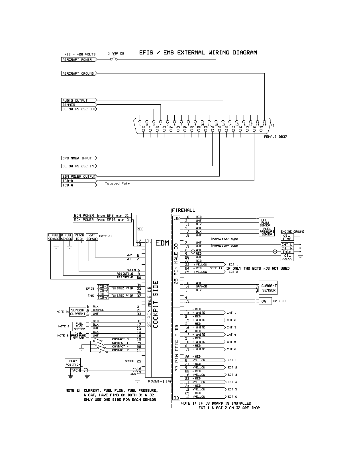
EMS / EDM Basic Wiring Diagram
TruTrak Flight Systems 17 EMS Installation Manual
JUNE 2009 8300-065 Rev D
Page 20

EDM ELECTRICAL PIN-OUT
J1 Pin
EDM Function / interior
1 Ground
2 Ground
3 Ground
4 Ground
5 Future Alert Lamp Not used at this time
6 Vertical Trim Position (PITCH) input Pitch Trim Input
7 OAT Thermister OAT Input
8 Fuel level Resistive in 2 Left tank Input
9 Fuel level Capacitance in 2 Left tank Input
10 Switch Contact 3 Input
11 Switch Contact 2 Input
12
MAIN EDM POWER
13
MAIN EDM POWER from second EFIS (optional)
14 Fuel Pressure Transducer Fuel Pressure Input
15 Fuel Flow Transducer Fuel Flow Input
16 TACH RPM Input
17 Ground
18 Ground
19
MAIN EDM AIRCRAFT GROUND
20 Sensor 5 volt supply
21 Sensor 5 volt supply
22 Sensor 5 volt supply
23 Sensor 5 volt supply
24 Lateral Trim Position Roll Trim Input
25 Flap Position Flap Position Input
26 Fuel level Resistive in 1 Right tank Input
27 Fuel level Capacitance in 1 Right tank Input
28 Switch Contact 4 Input
29 Switch Contact 1 / NINE CYLINDER SELECT SWITCH Input
30 Not used at this time
31 Sensor 12 volt supply
32 Air Pressure sensor
33 Current Transducer Battery Current Input
34
TCB-B (2)
35
TCB-A (2)
36
TCB-B
37
TCB-A
Notes
Sensor use only
Sensor use only
Sensor use only
Sensor use only
From EMS
From EFIS
Sensor use only
Sensor use only
Sensor use only
Sensor use only
Sensor use only
Sensor use only
Sensor use only
Nine Cylinder EDM
TruTrak Comm. Buss
TruTrak Comm. Buss
TruTrak Comm. Buss
TruTrak Comm. Buss
EDM CURRENT DRAW WEIGHT
Engine Data
Monitor
TruTrak Flight Systems 18 EMS Installation Manual
JUNE 2009 8300-065 Rev D
0.65 Amps @ 12v
0.65 Amps @ 24v
.5 lb 5.25L x 3.4W x 1. 5D
DIMENSIONS
Page 21

J2 Pin
EDM Function / Fire wall
1 Sensor Ground
2 TACH
3 Fuel Flow
4 OAT Thermister
5 Fuel Pressure
6 OIL pressure Sensor (Resistive type) Factory setup only
7 CHT 2 Thermister or Second OAT sensor (CARB TEMP)
8 Sensor 12 volt supply
9 Sensor 12 volt supply
10 Sensor 12 volt supply
11 Sensor Ground
12 Sensor Ground
13 Sensor Ground
14 Sensor 5 volt supply
15 Sensor 5 volt supply
16 Current Transducer
17 Not used at this time
18 Oil Temperature Thermister
19 CHT 1 Thermister
20 Oil Pressure
21 Not used at this time
22 - EGT 1 RED K type / # Nine EGT
23 + EGT 1 YELLOW K type / # Nine EGT
24 - EGT 2 RED K type / # Nine CHT
25 + EGT 2 YELLOW K type / # Nine CHT
Notes
Sensor use only
Sensor use only
Sensor use only
Sensor use only
Sensor use only
Sensor use only
Sensor use only
Sensor use only
Sensor use only
J3 Pin
TruTrak Flight Systems 19 EMS Installation Manual
JUNE 2009 8300-065 Rev D
EDM Function / Fire Wall
1 - CHT 1 J Type RED
2 - CHT 2 J Type RED
3 - CHT 3 J Type RED
4 - CHT 4 J Type RED
5 - CHT 5 J Type RED
6 - CHT 6 J Type RED
7
NO CONNECTION
8 + EGT 1 K type YELLOW
9 + EGT 2 K type YELLOW
10 + EGT 3 K type YELLOW
11 + EGT 4 K type YELLOW
12 + EGT 5 K type YELLOW
13 + EGT 6 K type YELLOW
14 + CHT 1 J Type WHITE
15 + CHT 2 J Type WHITE
16 + CHT 3 J Type WHITE
17 + CHT 4 J Type WHITE
18 + CHT 5 J Type WHITE
19 + CHT 6 J Type WHITE
20 - EGT 1 K type RED
21 - EGT 2 K type RED
22 - EGT 3 K type RED
23 - EGT 4 K type RED
24 - EGT 5 K type RED
25 - EGT 6 K type RED
NOT NINE CYL
NN OPTION
Page 22

EVEKTOR WIRING DIAGRAM
TruTrak Flight Systems 20 EMS Installation Manual
JUNE 2009 8300-065 Rev D
Page 23

ROTAX WIRING DIAGRAM
TruTrak Flight Systems 21 EMS Installation Manual
JUNE 2009 8300-065 Rev D
Page 24

EFIS AP / EMS / EDM BLOCK DIAGRAM
TruTrak Flight Systems 22 EMS Installation Manual
JUNE 2009 8300-065 Rev D
Page 25

NINE CYLINDER EDM BLOCK DIAGRAM
TruTrak Flight Systems 23 EMS Installation Manual
JUNE 2009 8300-065 Rev D
Page 26

J3 Pin
EDM Function / Fire Wall NINE CYLINDER OPTION
1 + EGT 7 K Type YELLOW
2 - EGT 6 K Type RED
3 + EGT 4 K Type YELLOW
4 - EGT 3 K Type RED
5 + EGT 1 K Type YELLOW
6
7
8
9
10 + CHT 7 J type WHITE
11 - CHT 6 J type RED
12 + CHT 4 J type WHITE
13 - CHT 3 J type RED
14 + CHT 1 J Type WHITE
15
16 + EGT 8 K Type YELLOW
17 - EGT 7 K Type RED
18 + EGT 5 K Type YELLOW
19 - EGT 4 K Type RED
20 + EGT 2 K type YELLOW
21 - EGT 1 K type RED
22
23
24
25 + CHT 8 J type WHITE
26 - CHT 7 J type RED
27 + CHT 5 J type WHITE
28 - CHT 4 J type RED
29 + CHT 2 J type WHITE
30 - CHT 1 J type RED
31 - EGT 8 K type RED
32 + EGT 6 K type YELLOW
33 - EGT 5 K type RED
34 + EGT 3 K type YELLOW
35 - EGT 2 K type RED
36
37
38
39
40 - CHT 8 J type RED
41 + CHT 6 J type WHITE
42 - CHT 5 J type RED
43 + CHT 3 J type WHITE
44 - CHT 2 J type RED
TruTrak Flight Systems 24 EMS Installation Manual
JUNE 2009 8300-065 Rev D
Page 27

TruTrak Flight Systems 25 EMS Installation Manual
JUNE 2009 8300-065 Rev D
Page 28

TruTrak Flight Systems 26 EMS Installation Manual
JUNE 2009 8300-065 Rev D
Page 29

TruTrak Flight Systems 27 EMS Installation Manual
JUNE 2009 8300-065 Rev D
Page 30

TruTrak Flight Systems No Penalty Upgrade Policy
As the product line continues to grow, it becomes increasingly difficult to maintain a simple upgrade policy. We do
want to reward our repeat customers by allowing a lower cost upgrade from one system to another; however we
are not able to offer this across the board on all products. If you are considering an upgrade, please call and we
will give you a quote on what this would cost. Many products that we sell today are upgradeable for only the
difference in system price. Because we continually strive to have the most up to date products possible, we
occasionally have to discontinue products. We will continue to offer discounted upgrades even for our discontinued
products.
TruTrak Flight Systems 28 EMS Installation Manual
JUNE 2009 8300-065 Rev D
Page 31

RETURN MERCHANDISE POLICY AND PROCEDURE
Under no circumstances should products be returned to TruTrak without first obtaining a Return of Merchandise
Authorization number (RMA #) from TruTrak. An RMA# may be obtained by contacting us at 866-878-8725.
Products that do not have an RMA # will not be processed.
Please include documentation stating the reason for the return and describing any symptoms, failure modes,
suspected causes of damage, diagnostics performed, data collected, etc.
Product(s) should be packaged in their original shipping containers. In lieu of this, they should be very carefully
packaged in containers suitable to protect them during transit. For your protection, items should be insured for the
full value. Note that damage caused during shipping will not be repaired under warranty.
The outside of the box must be clearly marked with the RMA # issued by TruTrak and the RMA # must also be
noted on the return documents.
Products will be returned to the customer at no charge via FedEx Ground or UPS Ground. If customer requests
expedited shipping (2
number.
INTERNATIONAL SHIPMENTS:
Trutrak sends all International shipments with an insurance value on all products. Trutrak pays for shipping only.
The customer is responsible for any and all additional fees, duties, taxes associated with the shipment.
When sending products to Trutrak for repair or otherwise please be advised that the customer is responsible for all
charges and fees associated with shipment. For your protection, items should be insured for the full value.
Trutrak states on all product returns “WARRANTY REPAIR AT NO CHARGE TO CUSTOMER. A COMMERCIAL
INVOICE VALUE OF $___ GIVEN FOR INSURANCE PURPOSE S ONLY”
Please keep in mind that your government or another entity in your country may impose a charge for custom and/or brokerage
fees, duties and taxes on items received from the US. These charges do not originate from our company nor do we benefit from
them in any way. You are responsible for payment of all custom and brokerage fees, duties and taxes that may be imposed
when these goods are imported into your country.
Send ALL return shipments to:
TruTrak Flight Systems, Inc., 1500 South Old Missouri Road, Springdale, AR 72764 USA
Attention: Returns Dept. RMA#
Warranty On TruTrak Flight Systems Products
We here at TruTrak Flight Systems know how important it is to feel as though the customer is purchasing a product
that the manufacturer is going to stand behind. For this reason we want offer more than the basic one year warranty
that is standard to this industry. The warranty on all TruTrak products will be three years from the date of
purchase. Abuse and misuse of a product are not covered under this warranty. Modification to a product may void
the warranty, as well as carry a penalty when upgrading to another product. This three year warranty will be for all
products except the Pictorial Turn & Bank, which will continue to have a warranty of one year from the date of
purchase.
nd
Day or Overnight) they will be charged the shipping cost and must supply a credit card
TruTrak Flight Systems 29 EMS Installation Manual
JUNE 2009 8300-065 Rev D
Page 32

TruTrak Flight Systems, Inc.
1500 S. Old Missouri Rd.
Springdale AR 72764
(479) 751-0250
FAX (479) 751-3397
www.trutrakap.com
 Loading...