

Page 1
EFIS Autopilot
Installation Manual
8300-057 Rev E
TRUTRAK FLIGHT SYSTEMS
1500 S. Old Missouri Road
Springdale, AR 72764
Ph. 479-751-0250 Fax 479-751-3397
www.trutrakflightsystems.com
Page 2

INSTALLATION MANUAL
FOR
EFIS Autopilots
TABLE OF CONTENTS
OPERATION OF THE BASIC FLIGHT INSTRUMENT ................................................1
OPERATION OF THE EFIS PILOT.................................................................................1
MECHANICAL CONSIDERATIONS..............................................................................2
PITOT AND STATIC CONNECTIONS...........................................................................2
RFI/EMI .............................................................................................................................2
BASIC SERVO INSTALLATION ....................................................................................3
THE DISPLAY ..................................................................................................................4
AUTOMATIC ARRIVAL TRANSITION.........................................................................5
OPERATING CONTROLS................................................................................................6
SETUP SCREENS .............................................................................................................8
AUTO PILOT SETTINGS...............................................................................................11
EFIS SOFTWARE UPDATES......................................................................................... 13
VNAV ..............................................................................................................................14
NAV INDICATOR...........................................................................................................14
AP LEVEL BUTTON (OPTION)....................................................................................14
INITIAL SETUP & GROUND CHECKOUT..................................................................16
FIRST FLIGHT................................................................................................................18
ELECTRICAL PIN-OUT .................................................................................................20
EFIS AP BASIC WIRING DIAGRAM...........................................................................22
EFIS AP BLOCK DIAGRAM.........................................................................................22
RETURN MERCHANDISE POLICY AND PROCEDURE...........................................33
Revision
A 07/01/2008 Initial Release
B 11/01/2008 Engine information 17,18, & 19
C 01/20/2009 Updated pictures & GPS information 4 - 14
D 04/14/2009 Updated engine information 13, 20, 21
E 09/14/2009 Added ARINC convert information 14, 24
Date Description Page #
Page 3

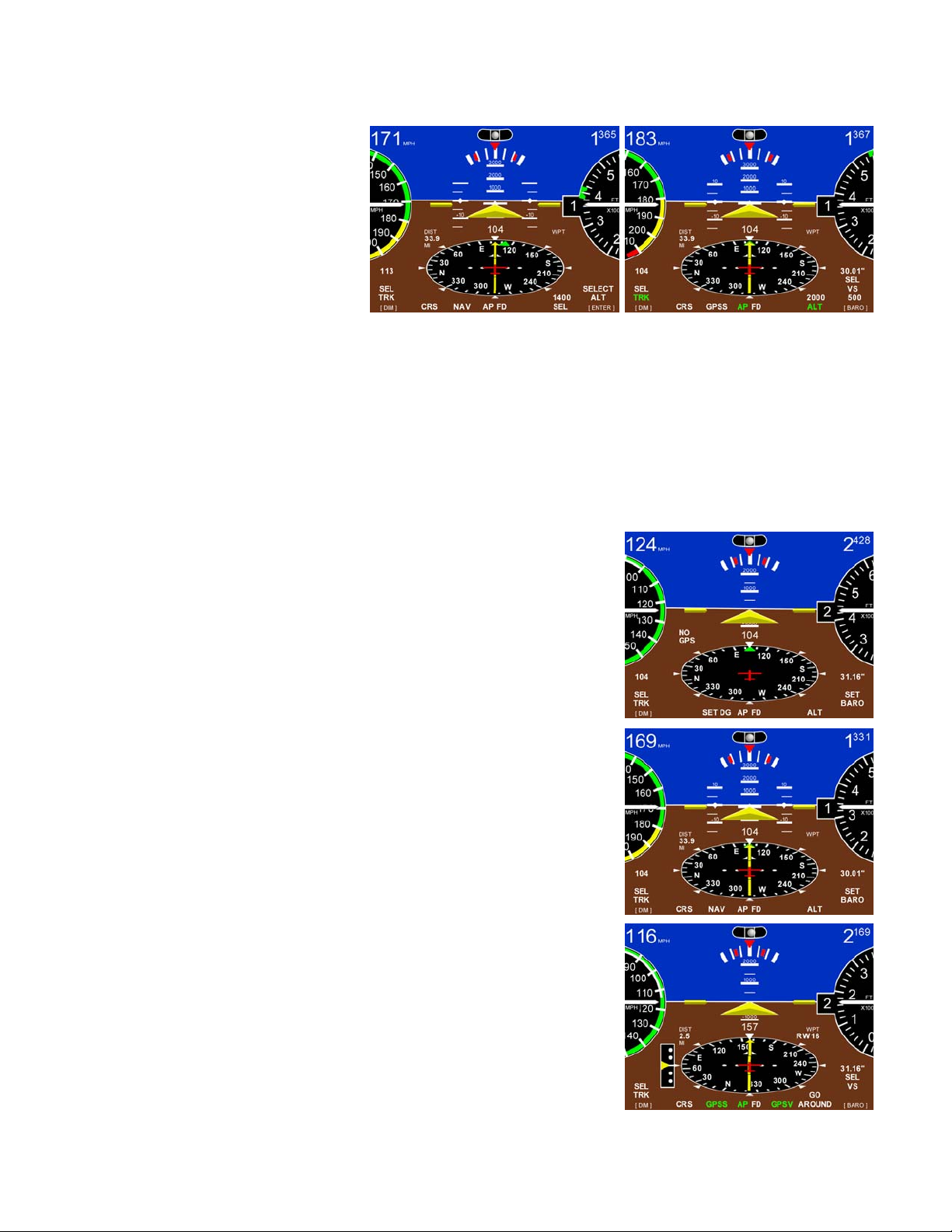
OPERATION OF THE BASIC FLIGHT INSTRUMENT
As with our autopilot products, extensive attention has been given to providing the
simplest operation. No sequential pressing of buttons is required to reach basic control functions
and no additional button pressing is required to set values. Starting with a clean sheet of paper
the layout of controls (two knobs and five soft keys) is sufficient to handle all EFIS and built in
autopilot control functions.
On the basic flight instrument, the right hand knob is primarily dedicated to setting the
barometer and the left hand knob is primarily dedicated to setting the direction bug. Pressing the
ALT soft key sets the altitude bug to the 100 foot mark nearest the present altitude. This setting
is entered into the active state by pressing the right hand knob. If the intent is to select an altitude
the ALT button is pressed and the right hand knob is rotated to select the desired altitude. (With
the knob out, steps are 500 feet and with the knob depressed, steps are 100 feet.) When the
altitude has been set, press the knob to ENTER the value. It will be noted that when any value is
to be set a screen showing the selection to be made will appear above the appropriate knob.
When the aircraft is within 30 miles of the destination fix, the CRS label will display on
the soft key at the far left. To select an arrival course different from the enroute course on the
HSI press CRS and then rotate the left hand knob. When the course is set press the knob to
ENTER. A computer generated arrival procedure in which steering from the enroute course to
the selected runway is described in the special functions section.
Just above the left knob is the label [DIM] in small print. To set the dimmer, press and
release the knob, then rotate to set the desired light intensity. When this is done, press and release
the knob to exit the set mode.
When there is NO GPS the directional gyro operates in the free gyro mode, and the label
above the far left soft key is SET DG. When this button is pressed, the left knob is used to set the
DG to the magnetic compass. As is the case with any free gyro this procedure is to be repeated
periodically as required.
OPERATION OF THE EFIS PILOT
When the autopilot is not engaged operation and labels are the same as the basic EFIS
except for the presence of the AP button. When the autopilot is engaged, the right hand knob is
dedicated to selecting vertical speed. The [BARO] label is now just above the right knob. To
adjust the barometer, press and release the knob to enter the Baro set mode, and then rotate the
knob, press and release the knob to ENTER. The button to the left of AP is labeled with NAV or
GPSS. This mode is turned on or off by pressing the knob. Rotation of the directional knob also
turns off the NAV or GPS mode. When GPSS mode is engaged GPSV appears above the button
to the right of AP. Further information on GPS steering is in the special functions section.
TruTrak Flight Systems 1 EFIS Autopilot Installation Manual
April 2009 8300-057 Rev D
Page 4

Mechanical Installation Considerations
PROGRAMMER INSTALLATION
Mounting Considerations
The EFIS Series unit is designed to mount in the aircraft instrument panel within view and reach of the
pilot. The primary unit location should minimize pilot head movement when transitioning between
looking outside of the cockpit and viewing/operating the EFIS Series unit. Maximum recommended
viewing angle should be no more than 20 deg. The maximum mounting angle the EFIS can accommodate
is 12 degrees longitudinal axis and 0 degrees lateral axis. The location should be such that the EFIS Series
unit is not blocked by the glare shield on top, or by the throttles, control yoke, etc. on the bottom. Use
aircraft installation standards for mounting and support of the EFIS programmer.
Wiring Considerations
Use AWG #24 or larger wire for all connections unless otherwise specified. The standard solder pin
contacts supplied in the connector kit are compatible with up to AWG #18 wire. In cases where some
installations have more than one component sharing a common circuit breaker, sizing and wire gauge is
based on, length of wiring and current draw on units. In these cases, a larger gauge wire such as AWG
#20 may be needed for power connections. Do not attach any wires to the outside of the EFIS or route
high current wires within six (6) inch of the programmer. Ensure that routing of the wiring is not exposed
to sources of heat, RF or EMI interference. Check that there is ample space for the cabling and mating
connectors. Avoid sharp bends in cabling and routing near aircraft control cables. Do not route the COM
antenna coax near any EFIS components.
RFI/EMI considerations
The EFIS programmer is shielded and does not generate any appreciable level of electromagnetic
interference. Moreover, the servo lines (except for power and ground) are low-current and cannot
contribute to RF interference. The servo power and ground lines do have switching currents through
them, but so long as there are no parallel runs of servo power and ground lines with such things as poorlyshielded antenna lines or strobe light power lines, there is no need to shield the servo harnesses. The
EFIS itself has been internally protected from RF interference and has been test ed under fairly extreme
conditions, such as close proximity to transmitting antennas. However, it is always good practice to
insure that such antennas are properly shielded and not routed directly over or under sensitive panelmounted electronic equipment. Most problems in this area are the result of improper RF shielding on
transmitting antennas, microphone cables, and the like. The most sensitive input to the autopilot is the
Control Wheel Switch input. This line should not be routed in parallel with transmitting antennas or
other sources of known RF interference. The CWS wire should be shielded with the shield connection to
pin 19 of the autopilot connector or a close suitable ground point.
Pitot and Static Connections
The TruTrak EFIS require connections to the Pitot and static lines, see page 8. The preferred method of
this connection would be tee fittings near the aircraft’s airspeed indicator. The importance of a good
static port and line cannot be overstated. In some cases, problems can be caused by having a large
number of devices connected to a single, insufficient, static port. In other cases, the static line itself is
adequate but there are one or more devices connected to the same line, one of which has a large static
reservoir. A simple remedy for this problem if it occurs is a tee-fitting near the static port, and a dedicated
line to the EFIS only or a dedicated static port close to the autopilot. Obviously, an insufficiently-large
orifice coupled with large static reservoirs can aggravate the problems associated with lag.
TruTrak Flight Systems 2 EFIS Autopilot Installation Manual
April 2009 8300-057 Rev D
Page 5

Servo Installation
The installation information in this section is extremely important and must be clearly
understood by the installer. Improper servo installation or failure to observe and diagnose
installation problems prior to flight can result in extremely serious consequences, including
loss of ability to control the aircraft. If there are any questions on the part of the installer it
is mandatory to resolve these questions prior to flight of the aircraft.
Most modern experimental aircraft use push-pull tubes to drive the primary controls. These tubes
generally have a total travel of 3” or less; therefore, it is best to connect the autopilot servo to the primary
control by the same method. This connection consists of an arm on the servo connected by a push-pull
rod to the primary control. Rod-end bearings are required on each end of the push-pull rod. The servo
arm must not rotate even near to the point called OVER CENTER, the point at which the primary aircraft
control would lock up. Some aircrafts mechanical primary control installations will not allow this to occur
and do not need the servo stops. This is a condition that would result from the servo being back driven
when the pilot operates the controls, or from the servo itself driving the controls to a stop. To protect
against this mechanical stops are supplied with the servos. These stops are drilled so that they can be
mounted at different angles as required (18° intervals)
In addition to the proper use of the stop it is important to know the amount of travel on the primary
control that the servo can handle. With the push rod connected to the outermost hole (1 ½”) the travel on
the primary cannot exceed 2 ½”, the intermediate hole 2 1/16”, and the inner hole 1 5/8”. It is important
to note that at the neutral point of the control the SERVO ARM must be PERPENDICULAR to the push
rod, and that the stop must be mounted so as to limit travel as near as possible to equal amounts in both
directions. In certain factory-designed installations there may be well-proven exceptions. There will be
installations in which space does not permit the use of the stop. When this is done the aircraft’s primary
control stops must be positive and care must be taken to be sure that at the neutral point the servo arm is
perpendicular to the push rod, and that the travel limits of the servo arm are not exceeded. There are
installations in which the travel of the push-pull tube exceeds the allowable 2 ½”. For such installations,
the drive can be applied to a bell crank at a radius point that moves the desired 2 ½” of maximum allowed
travel in the outermost hole of the arm.
When there is no way to have a drive point of less than 2 ½” or when the primary control is cable-driven
it is necessary to use the capstan-cable servo drive. When this is done the servo should be mounted so
that the 1/16” diameter cable which wraps around the capstan when extended parallel to the primary cable
is approximately 3/16” from the primary cable. If the primary control travel does not exceed 5” the cable
locking pin will be 180° away from the point at which the cable leaves the capstan. When the primary
control is at the neutral point this means the total cable wrap around the capstan is 360°. If the primary
control travel is greater than 5” the cable wrap is 720°and the pin is adjacent to the output point when the
primary control is at the neutral point.
The cable clamps when properly installed will not slip and thus get loose, but it is desirable to NICO press
or swedge a fitting on to the cable so as to provide added assurance that the cable will not become slack.
If the bridle cable is not sufficiently tight there will be lost motion in the autopilot drive. This will result
in hunting (oscillation).
TruTrak Flight Systems 3 EFIS Autopilot Installation Manual
April 2009 8300-057 Rev D
Page 6
THE DISPLAY
Consider first the pitch display. Motion of the pitch display short term is gyroscopic as it must be
to fly in IMC. Long term it is VSI. This is a special case of a presentation used in the military called
VELOCITY VECTOR. This display has two advantages. The first is that it provides an instantaneous
vertical speed presentation. The second is that when the reference airplane is on the horizon the aircraft is
neither climbing nor descending. This eliminates the need for adjusting the position of the pitch reference
airplane to compensate for the angle the fuselage is flying. The resulting benefit of this concept is that it
makes holding altitude easier (not only in straight flight but also in turns). It is a fact that next to AOA,
airspeed provides the best warning of approaching a stall. For this reason the airspeed pointer flashes red
when a pre-set minimum airspeed safely above a stall is reached. There are critics of this concept who
believe that attitude is an indicator of approaching a stall. NOT SO, attitude alone is not at all such an
indicator.
The HSI is placed below the horizon
as in the larger more expensive
displays. It is in the form of an
ellipse for two reasons. First, an
ellipse when compared with a circle
of the same height provides a broader
scale at the top where it is read.
Second, it looks as a circle would
when laid out on the ground ahead of
the aircraft. When a DIRECT TO or
FLIGHT PLAN is set into the GPS
this display becomes an HSI. The
boldness of this high quality display
in combination with its location
enhances the fly ability of the overall
instrument. Finally, the HSI contains
features that make functions available
that are not found in other low cost
systems. These are described in other sections.
The analog presentations of airspeed and altitude are based on the belief that in some cases round
is better. It will be noted that after having tried other presentations the automobile industry is back to
round instruments. Nothing in the modern world of vertical tapes compares with the dynamic effect of a
white needle moving around a black altimeter dial. As a target altitude is approached it is natural for the
pilot to slow the needle velocity so as to arrive at the altitude without overshoot. The difference is that in
this system the dials rotate about fixed pointers, but the relative motion retains the same effect as the
moving pointer. In addition, the rotating altimeter dial further enhances the motion factor. To satisfy
personal preference the display can be switched back and forth between round and rectangular, even in
flight. Of those who have tried both the choices have been almost unanimous in favor of the round.
Within the bank angle scale indicators are inserted which show the angle for a standard rate turn.
These indicators move outward on the bank angle scale as airspeed increases. Placed above the bank
angle scale is an inclinometer that looks just like a conventional ball in a curved tube.
Still another convenient feature is the optional presentation of important engine data in the pilot’s
direct field of vision displayed across the top of the instrument.
TruTrak Flight Systems 4 EFIS Autopilot Installation Manual
April 2009 8300-057 Rev D
Page 7
Automatic Arrival Transition
In an aircraft tracking a course inbound to a destination airport, the letters CRS will appear above
the far left soft key when the distance becomes less than 30 miles. When CRS is showing, the autopilot
can be programmed to fly a transition from the enroute arrival course to a selected arrival course set into
the HSI. This is not intended to be
used in an IFR approach but instead
as a convenience for the low time
pilot in arriving at an un-familiar
airport or for the over loaded pilot in
marginal VFR weather.
To initiate the automatic
arrival mode, press CRS, select the
desired runway course, and click the
APPR button. The autopilot will n
ow
fly the entire arrival path to the
desired runway. An additional
feature of the automatic arrival mode
can be used to position the aircraft
according to the desired right or left
hand pattern. After setting the
inbound course press enter instead of
APPR to remain in track mode. Once the desired aircraft position is established, press CRS then APPR to
initiate the automatic arrival. This procedure works regardless of the direction of the inbound course and
that of the selected approach course to the airport.
PRESS CRS – SELECT COURSE – PRESS APPR
TruTrak al
April 2009 8300-057 Rev D
Flight Systems 5 EFIS Autopilot Installation Manu
Page 8
Operating controls
As with our autopilot products, extensive attention has been given to providing the simplest operation.
No sequential pressing of buttons is required to reach basic control functions and no additional button
pressing is required to set values.
Button labels – White - mode is OFF
Green - mode is ON
Click – Momentarily push and release
any knob or button
Press – Push and hold any knob or
button for 2 seconds and release
Enter – Click appropriate knob
BARO & TRK SELECTION
In the TruTrak EFIS display, both barometer BARO and direction TRK are set by rotation of dedicated
knobs.
DIMMING
Dimming of the display is accomplished by a Click of the left knob
[DIM] and then rotating the knob Counter Clock wise to reduce the
display illumination. External dimmer input will only control the
button illumination.
DIRECTION GYRO
Normally this adjustment will not be necessary, as the HSI will be
slaved to a GPS NMEA source. If there is a loss of the GPS source
then the internal gyro backup will maintain the DG. Click the soft key
(button) beneath SET DG provides a screen for correction of any drift
in the DG that may occur by rotating the left knob to set the DG, and
then click ENTER.
Natural progression will be reduced with repeated DG SET.
TruTrak Flight Systems 6 EFIS Autopilot Installation Manual
April 2009 8300-057 Rev D
Page 9
ALTITUDE BUG
Click the soft key beneath ALT
provides a screen for preselecting
the altitude. The GREEN BUG on
the altimeter will move to the closest
100 ft mark of the current altitude.
Then rotating the right hand knob
SELECT ALT will allow the
altitude to be selected. Each step of
the rotary encoder moves the bug 500 ft. while depressing the knob and rotating provides 100 ft. steps and
then click ENTER. The altitude bug will never move out of view but will remain ether at the top of the
altimeter to indicate selected altitude is above current altitude or the bottom to indicate selected altitude is
below current altitude. The selected altitude setting can always be seen above the SEL or ALT after
selection on the display.
EFIS AP II will NOT preselect altitude in AP mode.
GPS INFORMATION
The HSI requires GPS NMEA information to function correctly. If the
primary serial connection and communication protocols have been
setup correctly, the EFIS display will display GPS/HSI information as
shown. If not then the Display will show NO GPS and only the DG
will be operational.
When a flight plan has been entered into the GPS, the HSI will display
a Course to the first waypoint. The deviation bar will offset to show
the aircraft present position compared to the desired track. The small
yellow diamond shaped bug is the DIRECTION TO WAYPOINT bug.
Setting the HSI CRS pointer is accomplished by clicking the soft key
beneath CRS to enter the set up screen. Rotation of the left knob
selects the course, click ENTER to set.
All EFIS with RS-232 (NMEA) input will have GPS NAV (NAV) but
will overfly the waypoint then intercept new the track at about a 45
degree angle.
The EFIS AP IV has the ability to perform GPSS and GPSV
commands from the programming of the GPS unit communicating
across ARINC wires to the EFIS AP. The GPSV requires a GPS
approach to communicate GPSV information to the EFIS AP IV.
Valid information is required to allow the GPSV button to be engaged.
When GPSS and/or GPSV are engaged the steering commands come
from the flight plan programmed in the GPS. See page 15.
AP IV SHOWN
TruTrak Flight Systems 7 EFIS Autopilot Installation Manual
April 2009 8300-057 Rev D
Page 10
SETUP SCREENS
STYLE, ATT, ZERO, INFO, UNITS, BALL, ALERTS, SPEEDS, SERIAL, LAT AP, YD, VRT AP,
AUDIO
To enter the setup screen the press
the right knob until SETUP shows
below the HSI then click the soft k
ey
below SETUP at the same time.
Click the button below any selection
to enter and adjust that function.
Click the MORE button or rotate
the right knob to progress through
the different setup selections.
With a dual EFIS system, most
setting that apply to both the EFIS
and EMS will change on both units
when set on one. With the EDM
(Engine Data Module) option,
engine information can be selected
under the ENGINE page.
See EMS installation manual for
more information.
Rotate the right knob NEXT on the first page to enter the AP setup pages.
Click the right knob to return to the main screen.
STYLE
Click ether ROUND gauge or RECT tape style airspeed and altimeter
gauges.
Click the right knob to return to the SETUP screen.
ATT & ZERO
Click ATT, OFF or ON to select
aircraft attitude indication in the
center of the EFIS horizon. This
will display the VSI indication on
the left side with round style and on
the right side with tape style gauges.
The attitude can be zeroed for level
flight for different aircraft by
clicking the ZERO soft key button
at any time.
TruTrak Flight Systems 8 EFIS Autopilot Installation Manual
April 2009 8300-057 Rev D
Page 11
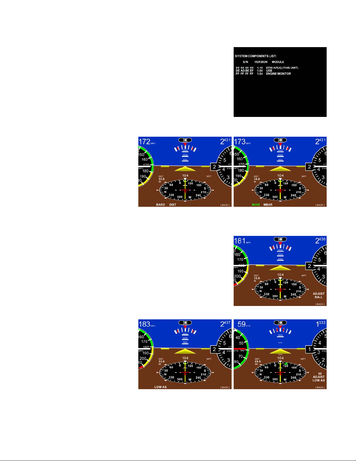
INFO
This button will display the information about all the components that
are connected to the EFIS communication buss, Serial numbers,
Software version, and Model type. The LEFT KNOB must be clicked
to return to the main page.
UNITS
Under this button the UNIT of
measure for the
BARO ( IN HG, MBAR) or
DIST (NM, MI, KM) readouts can
be set.
BALL
After installation in the aircraft, center the ball by rotating the right
knob.
Click the right knob to return to the SETUP screen.
ALERTS
LOW AS will set the airspeed
warning in KTS
or if set to “0” airspeed, OFF.
The airspeed (0-300 KTS) that is
selected by the right knob will cause
the needle on the airspeed gauge to
flash red below your selected
airspeed.
Click the right knob to return to the SETUP screen.
TruTrak Flight Systems 9 EFIS Autopilot Installation Manual
April 2009 8300-057 Rev D
Page 12

SPEEDS (airspeed limitation arcs)
Set for aircraft before first flight!
VSO
Bottom of the white arc.
The stall speed or the minimum steady flight speed in the
landing configuration.
VS Bottom of the green arc.
The stall speed or the minimum steady flight speed clean
configuration.
Top of the white arc.
VFE
Maximum flap extended speed.
VNO
Top of the green arc.
Maximum structural cruise speed.
VNE
Red line, Top of yellow arc.
Click the right knob to return to the SETUP screen.
Never exceed speed.
SERIAL
Select ether 4800 or 9600 Baud for correct GPS RS 232
communications.
Click the right knob twice to return to the MAIN screen.
TruTrak Flight Systems 10 EFIS Autopilot Installation Manual
April 2009 8300-057 Rev D
Page 13

AUTO PILOT SETTINGS
Rotate the right knob NEXT on the first setup page to enter the AP setup pages.
LAT AP VRT AP
ACTIVITY
(Setting range 0 – 36) The velocity at which the servo moves the
control surface. The higher the number the more movement you will
see in the control surface. With a standard servo (DSB-X, DSP-X)
you should start at 0 then work your way up in flight to set the level
for your aircraft. The High Torque Servo (DSB-HB, DSB-HC) has a
different gear ratio, so an Activity setting of 12 will be equal to about
0. With too low a setting the aircraft will hunt slowly and appear to be
lazy. With too high a setting the aircraft will hunt rapidly, and appear
nervous and jittery.
MICRO
(Setting Range 0-31) This is used to remove the significant lost motion in the control system, usually a
cable control system. Most aircraft do not need this changed from 0. An example of when one might
need to adjust microactivity is if flying in still air, there is a very slight wing rock that cannot be solved by
adjusting the ACTIVITY setting.
ROLL
(Setting Range 0-4) Most aircraft do not need this changed from 0.
Only aircraft type like CT & CUB that have adverse Yaw with turns
(rudder assist). We recommend factory assistance before adjusting this
value.
BANK
(Setting Range Low – MED – High) This setting limits the maximum
bank angle of the aircraft to approximately 13 degrees at the low
setting, 18 degrees at the medium setting, and 24 degrees at the high
setting.
STATIC
(Setting Range Low – MED – High) This setting is used to
compensate for lag in the aircraft static system. This setting is usually
not adjusted. This value is used to remove very slow hunting, of more
than 15 to 30 feet, in altitude hold when adjusting the activity setting
does not solve the problem. This is NOT the setting to adjust if there is slight nose bobble in still air; the
setting for that situation is HALF STEP. We recommend factory assistance before adjusting this value.
TruTrak Flight Systems 11 EFIS Autopilot Installation Manual
April 2009 8300-057 Rev D
Page 14

HALF-ST
(Setting Range N or Y) This setting will cause the servo to take smaller steps, but will also reduce the
torque available. Normally this setting is “N”, if the aircraft nose moves up and down very slightly in
VERY calm air, and it can be verified that the servo is only moving one step for each “bobble” of the
nose, then select “Y”. Only very light aircraft that are extremely pitch sensitive will need to adjust this
setting.
SPEEDS (AP)
MIN AS
(Setting Range 0 – 300) This setting is the minimum airspeed in knots
that the autopilot will fly the aircraft.
Example: If the aircraft is climbing and the power setting is not
adequate to maintain selected vertical speed setting, the autopilot will
lower the nose until MIN AIRSPD setting is met. The FD “Fly Bar”
will also indicate a decent needed and flash red until airspeed is
restored.
NOTE: Do not set MIN airspeed setting too low for approach speeds.
MAX AS
(Setting Range 0 – 300) This setting is the maximum airspeed in knots
that the autopilot will fly the aircraft.
Example: If the aircraft is in a decent and the power is not reduced so
as to keep the airspeed below the MAX AIRSPD setting, the autopilot
will raise the nose until MAX AIRSPD setting is met.
NOTE: If set too low, aircraft will ascend in high cruise air speed.
Y D
(Setting Range N or Y) This setting indicates if the aircraft has a Yaw Damper system installed.
YAW CENTR
(Setting Range -8 – 8) This setting is used to have the Yaw Damper keep the aircraft slip/skid indicator
centered when the Yaw system is engaged. Allow a few seconds for the Yaw System to respond to the
new setting.
YAW ACTVTY
(Setting Range 0 – 12) The velocity at which the servo moves the control surface. The higher the number
the more movement you will see in the control surface.
AUDIO
(Setting Range 0 – 32) This location turns the audio on or off or controls the volume of the Speech.
TruTrak Flight Systems 12 EFIS Autopilot Installation Manual
April 2009 8300-057 Rev D
Page 15

EFIS SOFTWARE UPDATES
Compact Flash Card Slot
The EFIS software is updated by inserting a Compact Flash card (CE) in
the back top slot. With the back of the card up. Software is available from
TruTrak to install on a flash card. Then apply power to the EFIS and
monitor the screen. Follow the instructions on the screen. When power is
reapplied to the EFIS, the new software will be installed.
If more than one unit is updated the software load will take longer.
Confirm the update by watching the display lower left side on startup for
the version number change.
PITOT STATIC
ENGINE INFORMATION
With the optional Engine Data
Module coupled to the EFIS the
display will be able to show engine
information at the top. The Trim
indicators will only be displayed
when trim adjust is performed or
below VSO.
The parameter reading will display
yellow when entering the yellow a
There will be a warning box at the bottom of the display when the parameter first enters the red arc. see
OIL PRESSURE. ACK will remove the warning box and VIEW will change the page to the detailed view
D
etail
ed information is located
under the PAGE button.
The first page after power
-up will
show the timer page so that the fue
and or trip information can be
updated before engine start.
The HSI information can alw
returned to by clicking the MAIN
button.
LIGHF
T DIRECTOR
he magenta wings that comT
show the aircraft positioning to follow to maintain TRK, VSI, NAV,
etc. commands. All the pilot has to do is keep the triangle in the
wings as they move to follow the commands the pilot told the EFI
perform. Example: A change in TRK will command the wings to
bank in the direction to acquire the new TRK. A command to clim
a new altitude will cause the wings to move up on the horizontal plan
to acquire the new altitude.
TruTrak Flight Systems 13 EFIS Autopilot Installation Manual
April 2009 8300-057 Rev D
rc.
l
ays be
e up when the FD button is pressed will
S to
b to
e
.
Page 16

VNAV
VNAV (vertical navigation) is the
ability to command the EFIS AP to
fly to a specified altitude in a
specified distance (max 99 miles).
Maximum VS descent is 3000
ft/min.
The FD and or AP must be engaged.
Click the ALT button and set your
new altitude below your current
altitude, do NOT click [ENTER].
Click the DIST button to select the
distance to the new altitude, Click
the right knob [ENTER].
The display will show VNAV and
the altitude and distance to the new
altitude hold. When the aircraft
reaches the new altitude, the EFIS
will enter altitude hold.
NAV Indicator
With the serial wires from the SL30 or ARINC Converter to the EFIS
connected. The EFIS will display the VOR / ILS NAV information on
the HSI. This information does not command the FD or AP. With a
valid NAV input, an ILS or VOR will be displayed over the CRS
label. Press and Hold the CRS button to display the information on
the HSI. The OBS radial will be displayed on the NAV unit also.
The SL30 Head Type must be set for SERIAL output (see SL30
installation manual)
AP LEVEL BUTTON (option)
The AP LEVEL button must be
installed in easy reach of both the
pilot and copilot positions. When
depressed, the AP button will always
do the same function. The Auto
Pilot and FD will engage and
capture current Track and
Altitude. If the Auto Pilot is
engaged, the AP will change to
Track and Altitude hold.
Any manual input change, other than TRK change, on the EFIS AP after the AP LEVEL button has been
press will return the AP to normal function.
The CWS if installed will function as normal.
TruTrak Flight Systems 14 EFIS Autopilot Installation Manual
April 2009 8300-057 Rev D
Page 17

GPSS /
GPSV APPROACH
EFIS AP IV ONLY
Program the GPS for an approach to
the airport and activate the
procedure.
Engage e
ther the AP for autopilot
control or the FD for hand flight.
Select GPSS and engage ALTitude Turning to inbound course.
hold in the EFIS AP IV.
Fly the approach along the GPSS
approach path. After the aircraft is
on long final, the GPS will send a
valid GPSV signal. The EFIS will
display the GPSV (white) to the
right of the AP/FD label.
f the signal is not valid the GPSV I
will display GV FLG.
When in a holding pattern the
display will be GV HLD. Press and release the button be
low GPSV to engage GV ARM.
At the time the Glide Path meets the
aircraft. See GP scale left of HSI.
The GV ARM will change to GPSV
and the aircraft will p
e FD wings will drop to follow the
th
itch down or
GP.
The GO AROUND will be display
ed and then start flashing for a GO around decision action, if needed.
When the GO AROUND button is
Clicked, the EFIS AP / FD will
change to TRK mode and pitc
h up
VS 500 fpm.
The EFIS will NOT follo
w the
Departure Hold flight plan.
TruTrak Flight Systems 15 EFIS Autopilot Installation Manual
April 2009 8300-057 Rev D
Page 18

Initial Setup & Ground C
ust be performed before first flight
M
Once wiring and servo insta
the ground
orrect values. Apply power to the EFIS autopilot. After approximately five seconds, the EFIS autopilot
c
. The first step is to enter the setup modes on the autopilot and set all parameters to their
heckout
llation are completed, the autopilot should be tested in the aircraft while on
is ready to be setup for operation.
UP SCREENS secFollow the SET
e sure and Set the airspeeds for
B your aircraft before first flight!
he next step in the checkout procedu is to rify that all servos run, and in the correct direction. Power
T re ve
up the EFIS autopilot and wait app
button to engage the autopilot. At th
the SET BARO will change to SEL
selected vertical speed (“SEL VS”)
II, you must engage the ALT hold b
or lift up if a tail dragger and wat
that you are moving the empennage
vertical speed to zero if not there al
rotate the knob clockwise until
point, the pitch servo should be ng the control yoke or stick back, in an effort to raise the nose of
the aircraft. Similarly, rota th b ter clockwise until minus several hundred feet per minute is coun
howing on the SEL VS field, the pitch servo should be moving the controls forward to lower the nose
s
te e kno
of the aircraft. If direction is incorrec
tion above to set the different settings.
roximately five seconds for EFIS warm-up. Then CLICK the AP
is point, the TRK and the AP will turn green and with AP III and IV,
VS to indicate that they are autopilot controls on the display; the
will be shown below the VS on the right. For autopilots with option
y clicking the ALT button. Then push down on the tail (empennage)
ch the elevator movement. The elevator MUST move in the direction
. If AP III or IV then use the Vertical Speed knob to set selected
ready. The pitch servo should stop, or move only very slowly. Now
several hundred feet per minute is showing on the SEL VS field. At this
movi
t, install or remove the jumper between pins 1 and 2 of the autopilot
connector.
he roll servo should also be responding at this time, rotate the left knob to move the green bug back to 0
T
if not there already. The servo should
the current selected TRK to a selec
way as to roll the aircraft to the right.
ols in the opposite direction to attempt a roll towards the left. If servo direction is not correct, the
contr
ires going to pins 4 and 5 of the roll servo (pins 32 and 33 on the main connector) must be reversed to
w
chieve the correct response. If a servo does not move at all, double check the wiring, power and ground
a
stop or move only very slowly. Rotated the knob clockwise from
ted a TRK to the right, the control yoke or stick MUST move in such a
Conversely, a rotation of the knob counter clockwise will move the
to the servos. If a servo jitters but does not actually rotate, check the wiring on the four servo drive lines
pins 2, 3, 4, and 5 on the servo) to that servo for continuity and correctness. If the servo does not seem to
(
ave any torque, check the relevant torque control line for continuity and correctness. The voltage on pin
h
6 of the servo should be approximately 5 volts, with th
on the power and ground wires the
servo will not move without help.
e AP engaged. Also if there is not adequate current
At this time, check that the servo ar
using an arm, c
perating range of the servo (a maximum of 100 degrees total rotation) and that when the controls are
o
heck that as the controls go from limit to limit the arm of the servo remains in the
centered, the connecting pushrod
systems, insure that the cabli
ontrols from stop to stop. Insure that the servo remains secure in its mounting and does not flex its
c
ounting bracket as it drives the control to its stops. For installations using an arm, insure that as the
m
ervo moves the control towards the end of control travel it does not cause the main control’s torque tube
s
TruTrak Flight Systems 16 EFIS Autopilot Installation Manual
April 2009 8300-057 Rev D
ng remains at proper tension and is properly secured as the servo moves the
m or capstan is properly operating the controls. For servo installations
is approximately perpendicular to the arm of the servo. For capstan
Page 19

flex in any way that could cause control system lockup at the extremes of servo travel. Insure that any
to
“lost motion” in the linkages
autopilot. Lost motion (dead zone) will result in wandering or
he next step in the check-out procedure is to verify that the serial input from the GPS receiver is being
T
properly received and interpreted. With the aircraft outside of any building, power up the GPS receiver
and the autopilot. While the GPS is acquiring, the display will show NO GPS FIX. After the GPS
receiver acquires its position, the autopilot will display the valid position data is available. If the display
shows NO GPS, even after it is kno
diagnosed and corrected.
is eliminated or minimized, in order to maximize the performance of the
slow “hunting” behavior in flight.
wn that the GPS unit has a position fix, the problem must be
Summary:
ENGAGE AUTOPILOT WITH FLIGHT CONTROL CENTERED,
ROTATE LEFT KNOB CLOCKWISE A FULL ROTATION. THE
FLIGHT CONTROL MUST MOVE TOWARD RIGHT. ROTATE
LEFT KNOB COUNTER CLOCKWISE, FLIGHT CONTROL MUST
MOVE BACK TOWARD LEFT.
ROTATE RIGHT KNOB TO 1000’ UP. FLIGHT CONTROL MUST
MOVE BACK. ROTATE RIGHT KNOB TO 1000’ DOWN. FLIGHT
CONTROL MUST MOVE FORWARD.
Yaw Damper Ground Checkout
For an EFIS with a Yaw Damper, the next step in the checkout procedure is to verify operation of the yaw
damper.
Set the YD
by clicking the AP button on the EFIS. Note: Any time the autopilot is off in normal flight the yaw
damper may be toggled on and off using the YD key, so long as the aircraft is not flying slower than the
preset minimum airspeed.
The aircraft should be on a level surface (with its “ball” centered) for this adjustment. With the toggle
switch on the YD controller “OFF” for centering (leveling). Adjust the leveling potentiometer (which
protrudes from the face of the yaw damper module) to stop the movement of the servo (rudder). Once the
proper adjustment is done, switch the toggle switch toward “gyro on”. Push the tail away from you and
confirm that the rudder moves in the direction that you pushed the tail (empennage). Press the AP button
to disengage the yaw damper, re-enter the YD setup with the above procedure, advance to the and set YD
ACTIVITY value to zero. This insures that the yaw damper adjustments do not complicate the first test
flight of the autopilot, confirm that the minimum airspeed is set to the desired value for actual flight. This
should be an indicated airspeed (in knots) which is safely above the sta
or climb out speeds. Make sure that the toggle switch on the Yaw Damper controller is toggled toward
“gyro on” for flight.
ACTIVITY in the EFIS to 15. Manually center the rudder and then engage the yaw damper
ll but not below normal approach
With autopilot and yaw is engaged push on tail and rudder must move in
direction you have pushed.
TruTrak Flight Systems 17 EFIS Autopilot Installation Manual
April 2009 8300-057 Rev D
Page 20

First Flight
The first flight should be done after having completed all the setup and testing on the ground. For the f
irst
flight, it is important that the GPS unit is properly functioning with the EFIS.
The two activity adjustments (LAT ACTVTY and VRT ACTVTY) determine how briskly the autopilot
responds to roll and pitch disturbances. They can be adjusted, in flight, over a wide range; thus the
autopilot can be tailored to adapt to any aircraft installation.
Each of the two activity adjustments covers a numeric range of 0 to 36. Unless the value for a pa
aircraft is provided by TruT
Most installatio
ns would ultimately require somewhat higher settings.
rak, it is advisable to start with a setting of zero and work up from there.
rticular
Prior to takeoff on the first flight, a barometer set will be required; the default value will always be 29.92.
On the the
AP but he
SEL (s
minute
second
to enter ACTVTY, default is 3. Rotate the knob to select
the valu in
conditi
respons
an incr gh a setting is chosen, the autopilot will be
jittery a t is responsive but not over-active. It will
be noted that a fairly limited range of acti
first flight, manually fly the aircraft to a suitable area for testing. Engage the autopilot using
ton. Observe that the TRK GREEN BUG now shows the captured present ground track and t
elected vertical speed) field shows the approximate present rate of climb or descent in feet pe
r
. Use the right knob to set the selected vertical speed to zero. Press the right knob for a few
s until SETUP is shown on the display in the same location that AP was, click the soft key below
the setting for the AP. Select the LAT AP then
e zero (0), and observe the resulting control movement. It is best if these adjustments are made
ons of moderate turbulence (the EFIS loves turbulence) so as to make it easy to observe the
e of the autopilot to disturbances. Increase the value one setting at a time, taking time to observe
easing level of control response. At some point, if too hi
nd over-active. Back the setting down until the autopilo
vity setting will be acceptable; too low a value will result in
sluggish response, while too high a value will result in nervous, inappropriate response. Within this
acceptable range there is room for individual preference; some people prefer a more aggressive autopilot
than others
. It should be noted that any builder can accomplish this adjustment procedure and no
professional is required. Once the desired LAT ACTVTY level is established, click the right knob to
return to the setup screen.
MICRO setting in most aircraft will be left at zero (0). Micro activity is used only in aircraft in which a
slow wing rock has been ob
in an aircrafts control system, and the micro activity setting is a way to compensate for the lost motion.
Once the desired MICROACTIVITY has been selected, click the right knob to return to the setup scree
served in very still air. Sometimes there will be a small amount of lost motion
n.
The HALF-STEP setting in most cases will not need to be changed. If the half step setting is set to ON,
then the roll servo will now have higher resolution, and take smaller steps. While this setting will make
the servo take smaller steps, it will decrease the amount of available torque. This setting should be left at
OFF, unless it is observe that the wing moves up and down very slightly while in straight and level flight
in very still air. Once this setting has been done, click the right knob to return to the setup screen.
BANK selection screen default is MED. Set the desired bank angle that is comfortable, options are LO
about 12.5 degs, MED about 19 degs, and HI about 25 degs. Once the BANK ANGLE has been selected
click the right knob to
Having set the autopilot for its proper roll response, it is time to move to the pitch axis adjustments
return to the setup screen.
. Click
,
the VRT AP button that is shown on the first set up screen. Then click ACTVTY, in the same manner as
was done for the roll axis, use the knob to find a setting which results in
the appropriate response. Again,
too high a value will be jittery or oscillatory and too low a setting will be sluggish and unresponsive.
Having found the desired VRT ACTIVITY setting, click the right knob to return to the setup screen.
TruTrak Flight Systems 18 EFIS Autopilot Installation Manual
April 2009 8300-057 Rev D
Page 21

MICRO setting
in most aircraft will be left at zero (0). Micro activity is used only in aircraft in which a
slow pitch rock has been observed in very still air. Sometimes there will be a small amount of lost motion
in an aircrafts control system, and the micro activity setting is a way to compensate for the lost motion.
Once the desired MICROACTIVITY has been selected, click the right knob to
return to the setup screen.
The HALF-STEP setting in most cases will not need to be changed. If the half step setting is set to ON,
then the roll servo will now have higher resolution, and take smaller steps. While this setting will m
the servo take smaller steps, it will decrease the amount of av
ailable torque. This setting should be left at
ake
OFF, unless it is observe that the wing moves up and down very slightly while in straight and level flight
in very still air. Click the right knob if the setting was not changed, to return to the setup screen.
STATIC LAG setting it is set to LOW at the factory but can vary betwe
en LOW, MED, or HIGH to suit a
particular static system. LOW value assumes a static system with very little “lag”; the HIGH value
assumes a fairly large amount of lag. To diagnose the lag of a particular system, it is necessary to be in
the altitude hold mode of the autopilot, prior to setting the STATIC LAG.
Once the autopilot is in altitude hold mode, re-enter the vertical setup mode. In still air, straight and le
flight, in altitude hold mode, observe whether the altitude appears to oscillate, or “hunt” slowly up a
vel
nd
down. If this is the case, it may be caused by several factors, one of which is the amount of lag in the
static system. Increasing the STATIC LAG value to MED or HIGH may cure the problem; however this
should be set to the smallest value that satisfactorily flies the aircraft in the pitch axis, as the larger the
value the less responsive the autopilot will be to vertical commands or altitude error. Other possible
causes of hunting in altitude hold are “lost motion” in the aircraft controls or too low a level of vertical
activity setting. Excessive lag in the static system itself can be caused by undersized static ports,
improperly placed ports, long static lines, or especially by attached equipment with large static reservoirs.
The autopilot can be adapted to cover a wide range of static systems, but in truly extreme cases it may
necessary to provide a separate static line for the autopilot so that other equipment attached to the por
be
t
does not degrade the autopilot’s performance. Click the right knob twice to return to the MAIN screen.
Yaw Damper First Flight
The Yaw Damper s
ystem requires adjustment of the yaw damper parameters. With the autopilot
disengaged, level the aircraft and hand-fly the aircraft in still air. Press YD to engage the yaw damper.
Then enter the setup screen for the YD. Select CENTR, Centering is adjustable from -8 to 8 and has
enough authority to move the ball approximately one and one half times the width of the ball in either
direction. (Coarse adjustment was made using the potentiometer in the yaw damper module during the
earlier Initial Checkout Procedure.) Adjust the centering so that the ball is centered. Once the YD
LEVELING has been set, click to return to the setup screen. The next field, ACTVTY, determines how
aggressively the yaw damper responds to yaw disturbances. Yaw damper activity can range from 0 (off)
to 12 (extremely aggressive). For this purpose it is best to find light to moderate turbulence so the effects
can be properly observed. Having found suitable conditions, use the knob to gradually increase the value
of YD ACTIVITY in order to obtain an appropriate level of response to yaw disturbances. Too hig
h a
value will result in rapid oscillation, while too low a value will essentially disable the quick response of
the yaw damper to turbulence. Within the acceptable range of operation, there is still room to account for
personal preferences. So long as the yaw damper’s ACTVTY value is not so high as to cause oscillation,
the response is simply set according to preference
and comfort. Once the ACTVTY has been set, click
the right knob twice to exit the setup mode.
The normal operation of the autopilot will turn the yaw damper on any time the autopilot is engaged and
the yaw damper will stay on after the autopilot is disengaged. During final approach and the diminishing
of the airspeed below the MIN AIRSPD setting, the yaw damper will automatically disengage. To
disengage the yaw damper prior to that point, simply use the YD button to toggle the yaw damper off.
TruTrak Flight Systems 19 EFIS Autopilot Installation Manual
April 2009 8300-057 Rev D
Page 22

Electrical Pin-out
EFIS with Yaw Damper will be covered in this manual.
The table below provides a brief explanation of each pin function on the main 37-pin connector P101.
P101 Autopilot Rear Connector (Viewed from rear of autopilot) or wire side of connector.
P101
Pin
Function Notes
1 Dedicated ground connection for Pitch Reverse Jumper.
Pitch Reverse Jumper,
2
present or absent, as follows:
Pin 2 open (no connect): Servo CCW (counter-clockwise) Î UP
Pin 2 Jumper to pin 1: Servo CW (clockwise) Î UP
3 NAV / TT Converter box RS-232 Output.
4 Dimmer connection
5 Yaw Damper Activity. A signal from the autopilot which sets the amount of response the yaw
damper exhibits to azimuth disturbances and “ball” deflection.
6 Yaw Damper Centering. A signal from the autopilot which is used for fine adjustment of the
“ball” in a yaw damper.
7 AP illumination, To AP LEVEL Button lamp
8 Yaw Damper Activate. A signal from the autopilot which turns on the yaw damper function. EFIS with Yaw
9 No Connection
10 Pitch Servo Torque Control. A signal from the autopilot to the pitch servo which sets the
amount of torque to be delivered by the servo.
11 Pitch Servo Trim Sensor. A signal from the pitch servo to the autopilot which indicates an
out-of-trim condition and its direction.
12 Autopilot Master (+12 to +28 V DC). The autopilot itself draws less than 3 ampere. Most of
the current required by the autopilot system is used by the servos (up to 1.5A per servo).
13 Audio signal Out. This pin may be wired to an unswitched input of an audio panel. The
autopilot uses various voice or tones to denote specific events (loss of GPSS, capture
Glideslope, etc). Volume is adjustable within a setup screen of the autopilot.
Pitch Servo control lines. These lines cause the stepping motor in the pitch servo to run in the
14
appropriate direction at the desired velocity. They are small-signal lines and do not have any
15
substantial current-carrying capability or require any special shielding. Connect to pitch servo
16
as shown on wiring diagram.
17
18 Future Use
19 Power Ground Connection. Provide #20 AWG to common grounding point.
20 CWS / AP LEVEL Button.
21 EMS switch Switch to ground
22 NO CONNECTION
Direction of servo arm / capstan rotation
(as viewed from face of the servo body)
for UP elevator
SL-30 NAV pin 4 RX
EFIS with Yaw
Damper only
EFIS with Yaw
Damper only
Damper only
attempt to
Do not
reverse servo
direction by
swapping wires
Unavailable at this time
TruTrak Flight Systems 20 EFIS Autopilot Installation Manual
April 2009 8300-057 Rev D
Page 23

Autopilot Rear Connections to P101 (Continued)
Notes P101 Function
Pin
23 SPARE SWT
24 No Connection
25 Primary Serial Input. Baud rate selectable, 4800 or 9600 baud. Automatically decodes
NMEA-0183, Garmin Aviation Format, or Apollo/UPSAT Moving-Map or GPSS format.
Provides directional reference to the autopilot.
26
27
ARINC-A
ARINC-B
Digital differential signals from Garmin, Sierra, or other panel-mount receiver
which provide directional steering commands (GPSS) to autopilot
28 Roll Servo Torque Control. A signal from the autopilot to the roll (aileron) servo which sets
the amount of torque to be delivered by the servo.
29 ALT RS232 OUT.
30 NAV / T -30 NAV pin 5 TX T Converter box RS-232 IN. SL
31 EDM Po
Roll (aileron) Servo control lines. These lines cause the stepping motor in the roll servo to run
in the appr
any substantial current-carrying capability or require any special shield ing. Connect to roll
32
servo as shown on wiring diagram.
3
3
3
4
35
Wiring to roll servo J201
wer Only
opriate direction at the desired velocity. They are small-signal lines and do not have
Direction of servo arm / capstan rotation
from face of the s(as viewed ervo body)
J101 Pin 32 Pin 33
for RIGHT aileron
Stan -5 ) Î RIGHT dard J201-4 J201 Servo CCW (counter-clockwise
Reversed J201- 5 J201-4 Servo CW
(clockwise) Î RIGHT
3 wisted pair 6 TCB-B. T
37 TCB-A Twisted pair
F
E IS AP
P10 GPS 196 295 296 396
Pins
1 GPS III GPS 92 GPS 195
RS 232 e t 25 11 Data out Data out Blue wire Blue wire Blue wire Blue wire Blue wir Blue wire Data ou
King KMD
150
Garmin Garmin Garmin Garmin Garmin Garmin Garmin
Unavailable at this time
Unavailable at this time
M Power only
ED
Reverse servo
irection if necessary
d
y swapping wires on
b
pin 32 and 33.
Garmin
AvMap E
496
IV
KP
ARINC A 26 N/C N/C N/C N/C N/C N/C N/C N/C C N/C N/
AR B C N/C N/C INC 27 N/C N/C N/C N/C N/C N/C N/C N/
your GPS operation or installation guide for current interface information.
See
IS AP Garmin Garmin Garmin Garmin Garmin
EF
P101 Pins 155XL 200XL 300XL GX 50-65 GNS 480
RS 232 56 56 25 19 19 19 5 / 22 P1- 22
ARI ANC 26 16 16 16 N/C P5 - 4 46 46
AR B 47 INC 27 15 15 15 N/C P5 - 24 47
Garmin 430
P4001
Garmin 530
P5001
DIM
IS AP SERIES
EF
A
CURRENT DRAW CURRENT DRAW
LOW BRIGHT HIGH BRIGHT
1.07 Amps @ 12v
0.65 Am
ps @ 24v
2.02 Amps @ 12 v
1.15 Amps @ 24v
WEIGHT
2.33 lbs High bright
6.375W x 5.75LL
1.95 lbs Low bright
ENSIONS
Behi d panel
n
H x 3.625D
TruTrak Flight Systems 21 EFIS Autopilot Installation Manual
April 2009 8300-057 Rev D
Page 24

EFIS AP Basic Wiring D
iagram
E ck D ram
FIS AP Blo iag
TruTrak Flight Systems 22 EFIS Autopilot Installation Manual
April 2009 8300-057 Rev D
Page 25

EFIS AP with Options
TruTrak Flight Systems 23 EFIS Autopilot Installation Manual
April 2009 8300-057 Rev D
Page 26

TruTrak Flight Systems 24 EFIS Autopilot Installation Manual
April 2009 8300-057 Rev D
Page 27

Panel Templates
TruTrak Flight Systems 25 EFIS Autopilot Installation Manual
April 2009 8300-057 Rev D
Page 28

TruTrak Flight Systems 26 EFIS Autopilot Installation Manual
April 2009 8300-057 Rev D
Page 29

TruTrak Flight Systems 27 EFIS Autopilot Installation Manual
April 2009 8300-057 Rev D
Page 30

AP I Quick Reference
Button labels – White - mode is OFF, Green - mode is ON
Click – Momentarily push and release any knob or button
Press – Push and hold any knob or button for 2 seconds and release
Enter – Click knob labeled
Barometer adjust – Rotate right knob
Track bug adjust – Rotate left knob
Altimeter bug adjust – Click ALT button, bug will synchronize to nearest 100 feet
Rotate right knob to select new altitude (Depress knob for 100 ft resolution)
Click
[ Enter ]
Altimeter bug cancel – Click ALT button
Dimmer function – Click left knob to enter setup mode Rotate left knob to set desired brightness
Click
[ Enter ]
Nav mode – Click NAV button
Nav mode cancel – Click NAV button or rotate left knob (Track bug adjust)
Autopilot and Flight Director Operation
Autopilot on / off – Click AP / FD button – on, Click AP / FD button – off
Flight Director on / off – Press AP / FD button – on, Press AP / FD button – off
Track select – Rotate left knob
Nav mode – Click NAV button
Nav mode cancel – Click NAV button or rotate left knob (Track select)
Altitude select – Click ALT button, bug will synchronize to (only available in FD) nearest 100 feet
Rotate right knob to select new altitude (Depress knob for 100 ft resolution)
Click
Barometer adjust – Rotate right knob
Dimmer function – Click left knob to enter setup mode. Rotate left knob to set desired brightness
Click
(Note: Operation is the same regardless of AP or FD being on or off)
Arrival Transition – Click CRS
Rotate left knob to set HSI course pointer to selected runway direction
Click APPR
[ Enter ] (VS is fixed at +/- 500 FPM)
[ Enter ]
[ Enter ]
Basic Operation
Arrival Transition
TruTrak Flight Systems 28 EFIS Autopilot Installation Manual
April 2009 8300-057 Rev D
Page 31

AP II Quick Reference
Button labels – White - mode is OFF, Green - mode is ON
Click – Momentarily push and release any knob or button
Press – Push and hold any knob or button for 2 seconds and release
Enter – Click knob labeled
Barometer adjust – Rotate right knob
Track bug adjust – Rotate left knob
Altimeter bug adjust – Click ALT button, bug will synchronize to nearest 100 feet
Rotate right knob to select new altitude (Depress knob for 100 ft resolution)
Click
[ Enter ]
Altimeter bug cancel – Click ALT button
Dimmer function – Click left knob to enter setup mode
Rotate left kno
Click
[ Enter ]
Nav mode – Click NAV button
av mode cancel – Click ust)
NAV button or rotate left knob (Track bug adjN
Autopilot and Flight Director Operation
Autopilot on / off – Click AP / FD button – on, Click AP / FD button – off
Flight Directo – Press AP / FD bu
Track selec – Rotate left knob
Nav mode – Click NAV button
Nav mode cancel – Click NAV button or rotate left knob (Track select)
ltitude old
A h – Click ALT button, AP will synchronize to nearest 100 feet
Barometer adjust – Rotate right knob
Dimmer function – Click left knob to e
Click
Arrival Transition – Click CRS
Rotate left k
Click APPR
r on / off tton – on, Press AP / FD button – off
t
[ Enter ]
nob to set HSI course pointer to selected runway direction
[ Enter ]
Basic Operation
b to set desired brightness
nter setup mode. Rotate left knob to set desired brightness
Arrival Transition
same regardless of AP(Note: Operation is the or FD being on or off)
TruTrak Flight Systems 29 EFIS Autopilot Installation Manual
April 2009 8300-057 Rev D
Page 32

AP III Quick Reference
Button labels – White - mode is OFF, Green - mode is ON
Click – Momentarily push and release any knob or button
Press – Push and hold any knob or button for 2 seconds and release
Enter – Click appropriate knob
Basic Operation
Barometer adjust – Rotate right knob
Track bug adjust – Rotate left knob
ltimete bug adjust A r – Click ALT button, bug will synchronize to nearest 100 feet
ob to select new altitude Rotate right kn
Push Enter
cel Altimeter bug can – Click ALT button
immer function D – Click left knob to enter setup mode
b to set desired brightness Rotate left kno
Push Enter
Nav mode – Click NAV button
av mode cancel – Click NAV button or rotate left knob (Track bug adjust) N
Basi tion
c Autopilot and Flight Director Opera
Autopilot on / off – Click AP–FD button – on, Click AP–FD button - off
r on / off tton – on, Press AP–FD button - off Flight Directo – Press AP–FD bu
t Track selec – Rotate left knob
Nav mode – Click NAV button
ncel Nav mode ca – Click NAV button or rotate left knob (Track select)
ug will synchronize to nearest 100 feet Altitude select – Click ALT button, b
Rotate right knob to select new altitude Push Enter (Initial VS is +/- 500 FPM)
ob Vertical speed adjust – Rotate right kn
arometer adjust – Click right knoB
Rotate right kn r setting
Push Enter
Dimmer function sired brightness
Push Enter
Arrival Transition – Click CRS
Rotate left knob to set HSI course pointer to selected runway direction
Click APPR
– Click left knob to enter setup mode. Rotate left knob to set de
b to enter setup mode
ob to adjust baromete
Arrival Transition
same regardless of AP or FD being on or off) (Note: Operation is the
NOTES
AP IV Quick Reference
TruTrak Flight Systems 30 EFIS Autopilot Installation Manual
April 2009 8300-057 Rev D
Page 33

AP IV Quick Reference
Button labels – White - mode is OFF, Green - mode is ON
Click – Momentarily push and release any knob or button
Press – Push and hold any knob or button for 2 seconds and release
[ Enter ]
Basic Operation
Barometer adjust – Rotate right knob
Track bug adjust – Rotate left knob
Altimeter bug adjust – Click ALT button, bug will synchronize to nearest 100 feet
Click
[ Enter ]
Altimeter bug cancel – Click ALT button
Dimmer function – Click left knob to enter setup mode.
Click
[ Enter ]
Nav mode – Click NAV button
cancel orNav mode – Click NAV button
rotate left knob (Track bug adjust)
Autopilot and Flight Director Operation
–
Flight Director on – Press AP / FD button – on, Press AP / FD button –
/ off off
Click AP / FD button – on, Click AP / FD button – off Autopilot on / off
Track select – Rotate left knob
Nav mode – Click NAV button
nc r rotate left knob (Track select)
caNav mode el – Click NAV button o
GPS Steering – Click GPSS button
el
a cGPS Steering c n – Click GPSS button or rotate left knob (Track select)
ltitude elect A s – Click ALT button, bug will synchronize to nearest 100 feet
to select new altitude (Depress knob for 100 ft resolution) Rotate right knob
Click
Vertical speed adju – Rotate right knob
st
VNAV – below current (Depress knob for 100
[ Enter ] (Initial VS is +/- 500 FPM
otate right knob to select altitude Click ALT, R
ft resolution) Click DIST, Rotate right knob to select desired dist ance, Click
will appear when available) WAAS approach – Click GPSS (GPSV
Click GPSV (Glide slope scale will app
Missed approach – Click GO ARO ct and + 500 FPM climb)
Barometer adjust just barometer setting
– Click right knob to enter setup mode, Rotate right knob to ad
[ Enter
Click
UND (Enters Track sele
]
immer function D – Click left knob to enter setup mode Rotate left knob to set desired brigh
[ Enter ]
Click
Arrival Transition
(Note: Operation is the same rega less of AP or FD being on or off)
Arrival Transition – Click CRS, Rotate left kn to set HSI course pointer to selected ru nway direction
Click APPR
rd
ob
Enter – Click knob labeled
(Depress knob for 1 Rotate right knob to select new altitude
00 ft resolution)
Rotate left knob to set desired brightness
)
ter ]
[ En
ear)
tness
TruTrak Flight Systems 31 EFIS Autopilot Installation Manual
April 2009 8300-057 Rev D
Page 34

T
ruTrak Flight Systems No Penalty U
As the product line co nue grow, it becomes increasingly difficult to maintain a
want to re at cu ers by allowing a lower cost upgrade from one system to another; ho
are not ab ff acr he board on all products. If you are considering an upgrade, plea
will giv y uo what this would cost. Many products
ward our repe stom wever we
le to o er this oss t se call and we
e ou a q te on that we sell today are upgradeable for only the
nti s to simple upgrade policy. We do
difference in system price. Because we continu most up to date products possible, we
sionally have to discontinue products. We iscounted upgrades even for our disco ntinued
products.
pgrade Policy
ally strive to have the
will continue to offer docca
TruTrak Flight Systems 32 EFIS Autopilot Installation Manual
April 2009 8300-057 Rev D
Page 35

RETURN MERCHANDISE POLICY AND PROCEDURE
Under no circumstances should products be returned to TruTrak without first obtaining a Return of Merchandise
Authorization number (RMA #) from TruTrak. An RMA# may be obtained by contacting us at 866-878-8725.
Products that do not have an RMA # will not be processed.
Please include documentation stating the reason for the return and describing any symptoms, failure modes,
suspected causes of damage, diagnostics performed, data collected, etc.
Product(s) should be packaged in their original shipping containers. In lieu of this, they should be very carefully
packaged in containers suitable to protect them during transit. For your protection, items should be insured for the
full value. Note that damage caused during shipping will not be repaired under warranty.
The outside of the box must be clearly marked with the RMA # issued by TruTrak and the RMA # must also be
noted on the return documents.
Products will be returned to the customer at no charge via FedEx Ground or UPS Ground. If customer requests
expedited shipping (2
number.
INTERNATIONAL SHIPMENTS:
TruTrak sends all International shipments with an insurance value on all products. TruTrak pays for shipping
only. The customer is responsible for any and all additional fees, duties, taxes associated with the shipment.
When sending products to Trutrak for repair or otherwise please be advised that the customer is responsible for all
charges and fees associated with shipment. For your protection, items should be insured for the full value.
Trutrak states on all product returns “WARRANTY REPAIR AT NO CHARGE TO CUSTOMER. A COMMERCIAL
INVOICE VALUE OF $___ GIVEN FOR INSURANCE PURPOSE S ONLY”
Please keep in mind that your government or another entity in your country may impose a charge for custom and/or brokerage
fees, duties and taxes on items received from the US. These charges do not originate from our company nor do we benefit
from them in any way. You are responsible for payment of all custom and brokerage fees, duties and taxes that may be
imposed when these goods are imported into your country.
Send ALL return shipments to:
TruTrak Flight Systems, Inc.,
1500 South Old Missouri Road
Springdale, AR 72764 USA
Attention: Returns Dept. RMA#
Warranty On TruTrak Flight Systems Products
We here at TruTrak Flight Systems know how important it is to feel as though the customer is purchasing a product
that the manufacturer is going to stand behind. For this reason we want offer more than the basic one year warranty
that is standard to this industry. The warranty on all TruTrak products will be three years from the date of
purchase. Abuse and misuse of a product are not covered under this warranty. Modification to a product may void
the warranty, as well as carry a penalty when upgrading to another product. This three year warranty will be for all
products except the Pictorial Turn & Bank, which will continue to have a warranty of one year from the date of
purchase.
nd
Day or Overnight) they will be charged the shipping cost and must supply a credit card
TruTrak Flight Systems 33 EFIS Autopilot Installation Manual
April 2009 8300-057 Rev D
Page 36

TruTrak Flight Systems, Inc.
1500 S. Old Missouri Rd.
Springdale AR 72764
(479) 751-0250
FAX (479) 751-3397
www.trutrakap.com
 Loading...