

Page 1
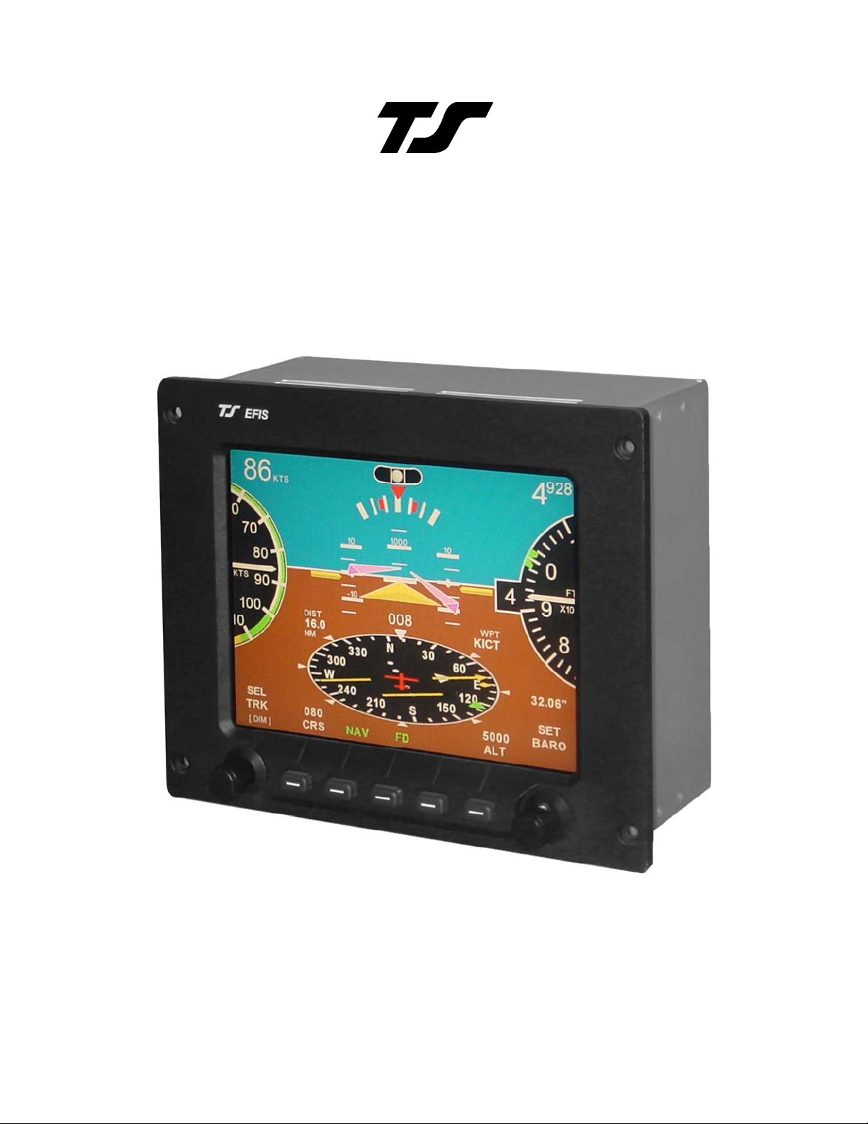
EFIS
Installation & Operation Manual
8300-056 Rev B
TRUTRAK FLIGHT SYSTEMS
1500 S. Old Missouri Road
Springdale, AR 72764
Ph. 479-751-0250 Fax 479-751-3397
www.trutrakflightsystems.com
Page 2

INSTALLATION MANUAL
FOR
EFIS
TABLE OF CONTENTS
OPERATION OF THE BASIC FLIGHT INSTRUMENT ..............1
THE DISPLAY .................................................................................2
MECHANICAL INSTALLATION CONSIDERATIONS ..............3
PITOT AND STATIC CONNECTIONS.......................................... 3
RFI/EMI ............................................................................................3
OPERATING CONTROLS .............................................................. 4
GPS INFORMATION.......................................................................5
SL 30 INFORMATION ....................................................................5
AUTOMATIC ARRIVAL TRANSITION.......................................6
SETUP SCREENS ............................................................................7
EFIS SOFTWARE UPDATES.......................................................10
ELECTRICAL PIN-OUT................................................................11
EFIS WIRING DIAGRAM.............................................................13
EFIS PILOT’S GUIDE ...................................................................19
RETURN MERCHANDISE POLICY AND PROCEDURE.........21
Revision Date Description Page #
A 07/0/1/2008 Initial Release
B 02/12/2009 Updated pictures & added SL 30 All
Page 3

OPERATION OF THE BASIC FLIGHT INSTRUMENT
As with our autopilot products, extensive attention has been given to providing the
simplest operation. No sequential pressing of buttons is required to reach basic control functions
and no additional button pressing is required to set values. Starting with a clean sheet of paper the
layout of controls (two knobs and five soft keys) is sufficient to handle all EFIS and built in
autopilot control functions.
On the basic flight instrument the right hand knob is primarily dedicated to setting the
barometer and the left hand knob is primarily dedicated to setting the direction bug. Pressing the
ALT soft key sets the altitude bug to the 100 foot mark nearest the present altitude. This setting
is entered into the active state by pressing the right hand knob. If the intent is to select an altitude
the ALT button is pressed and the right hand knob is rotated to select the desired altitude. (with
the knob out steps are 500 feet and with the knob depressed steps are 100 feet.) When the altitude
has been set press the knob to ENTER the value. It will be noted that when any value is to be set
a screen showing the selection to be made will appear above the appropriate knob.
When the aircraft is within 30 miles of the destination fix the CRS labels the soft key at the
far left. To select an arrival course different from the enroute course on the HSI press CRS and
then rotate the left hand knob. When the course is set press the knob to ENTER. A computer
generated arrival procedure in which steering from the enroute course to the selected runway is
described in the special functions section.
Just above the left knob is the label [DIM] in small print. To set the dimmer press and
hold the knob in for approximately one second, then rotate to set the desired light intensity.
When this is done press the knob to exit the set mode.
When there is NO GPS FIX the directional gyro operates in the free gyro mode, and the
label above the far left soft key is SET DG. When this button is pressed the left knob is used to
set the DG to the magnetic compass. As is the case with any free gyro this procedure is to be
repeated periodically as required.
TruTrak Flight Systems 1 EFIS Installation Manual
February 2009 8300-056 Rev B
Page 4
THE DISPLAY
Consider first the pitch display. Motion of the pitch display short term is gyroscopic as it must be to fly in
IMC. Long term it is VSI. This is a special case of a presentation used in the military called VELOCITY VECTOR.
This display has two advantages. The first is that it provides an instantaneous vertical speed presentation. The
second is that when the reference airplane is on the horizon the aircraft is neither climbing nor descending. This
eliminates the need for adjusting the position of the pitch reference airplane to compensate for the angle the
fuselage is flying. The resulting benefit of this concept is that it makes holding altitude easier (not only in straight
flight but also in turns). It is a fact that next to AOA, airspeed provides the best warning of approaching a stall. For
this reason the airspeed pointer flashes red when a pre-set minimum airspeed safely above a stall is reached.
There are critics of this concept who believe that attitude is an indicator of approaching a stall. NOT SO, attitude
alone is not at all such an indicator.
The HSI is
placed below the
horizon as in the larger
more expensive
displays. It is in the
form of an ellipse for
two reasons. First, an
ellipse when compared
with a circle of the
same height provides a
broader scale at the top
where it is read.
Second, it looks as a
circle would when laid
out on the ground
ahead of the aircraft.
When a DIRECT TO or
FLIGHT PLAN is set
into the GPS this
display becomes an
HSI. The boldness of
this high quality display
in combination with its
location enhances the
flyability of the overall
instrument. Finally, the
HSI contains features that make functions available that are not found in other low cost systems. These are
described in other sections.
better. It will be noted that after having tried other presentations the automobile industry is back to round
instruments. Nothing in the modern world of vertical tapes compares with the dynamic effect of a white needle
moving around a black altimeter dial. As a target altitude is approached it is natural for the pilot to slow the needle
velocity so as to arrive at the altitude without overshoot. The difference is that in this system the dials rotate about
fixed pointers, but the relative motion retains the same effect as the moving pointer. In addition, the rotating
altimeter dial further enhances the motion factor. To satisfy personal preference the display can be switched back
and forth between round and rectangular, even in flight. Of those who have tried both the choices have been
almost unanimous in favor of the round.
indicators move outward on the bank angle scale as airspeed increases. Placed above the bank angle scale is an
inclinometer that looks just like a conventional ball in a curved tube.
Still another convenient feature is the optional presentation of important engine data in the pilot’s direct field
of vision displayed across the top of the instrument.
The analog presentations of airspeed and altitude are based on the belief that in some cases round is
Within the bank angle scale indicators are inserted which show the angle for a standard rate turn. These
TruTrak Flight Systems 2 EFIS Installation Manual
February 2009 8300-056 Rev B
Page 5
Mechanical Installation Considerations
PROGRAMMER INSTALLATION
Mounting Considerations
The EFIS Series unit is designed to mount in the aircraft instrument panel within view and reach of the
pilot. The primary unit location should minimize pilot head movement when transitioning between
looking outside of the cockpit and viewing/operating the EFIS Series unit. Maximum recommended
viewing angle should be no more than 20 deg. The maximum mounting angle the EFIS can accommodate
is 12 degrees longitudinal axis and 0 degrees lateral axis. The location should be such that the EFIS Series
unit is not blocked by the glare shield on top, or by the throttles, control yoke, etc. on the bottom. Use
aircraft installation standards for mounting and support of the EFIS programmer.
Wiring Considerations
Use AWG #24 or larger wire for all connections unless otherwise specified. The standard solder pin
contacts supplied in the connector kit are compatible with up to AWG #18 wire. In cases where some
installations have more than one component sharing a common circuit breaker, sizing and wire gauge is
based on, length of wiring and current draw on units. In these cases, a larger gauge wire such as AWG
#20 may be needed for power connections. Do not attach any wires to the outside of the EFIS or route
high current wires within six (6) inch of the programmer. Ensure that routing of the wiring is not exposed
to sources of heat, RF or EMI interference. Check that there is ample space for the cabling and mating
connectors. Avoid sharp bends in cabling and routing near aircraft control cables. Do not route the COM
antenna coax near any EFIS components.
RFI/EMI considerations
The EFIS programmer is shielded and does not generate any appreciable level of electromagnetic
interference. The EFIS itself has been internally protected from RF interference and has been tested
under fairly extreme conditions, such as close proximity to transmitting antennas. However, it is always
good practice to insure that such antennas are properly shielded and not routed directly over or under
sensitive panel-mounted electronic equipment. Most problems in this area are the result of improper RF
shielding on transmitting antennas, microphone cables, and the like.
Pitot and Static Connections
The TruTrak EFIS require connections to the Pitot and
static lines. The preferred method of this connection
would be tee fittings near the aircraft’s airspeed indicator.
The importance of a good static port and line cannot be
overstated. In some cases, problems can be caused by
having a large number of devices connected to a single,
insufficient, static port. In other cases, the static line itself
is adequate but there are one or more devices connected to
the same line, one of which has a large static reservoir. A
simple remedy for this problem if it occurs is a tee-fitting
near the static port, and a dedicated line to the EFIS only or
a dedicated static port close to the autopilot. Obviously, an
insufficiently-large orifice coupled with large static
reservoirs can aggravate the problems associated with lag. PITOT STATIC
TruTrak Flight Systems 3 EFIS Installation Manual
February 2009 8300-056 Rev B
Page 6
Operating Controls
As with our autopilot products, extensive attention has been given to providing the simplest operation.
No sequential pressing of buttons is required to reach basic control functions and no additional button
pressing is required to set values.
BARO & TRK SELECTION
In the TruTrak EFIS display,
both barometer BARO and
direction TRK, the green
triangle bug, are directly set
by rotation of dedicated
knobs.
DIMMING
Dimming of the display is
accomplished by press and
release of the left knob
[DIM] and then rotating the
knob Counter Clock wise to
reduce the display
illumination. External
dimmer input will only
control the button
illumination.
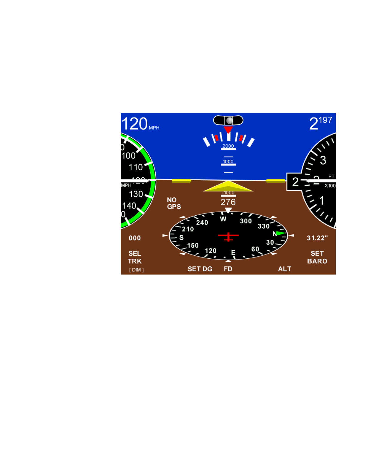
DIRECTION GYRO
Normally this adjustment will not be necessary as the HSI will be slaved to a GPS NMEA source. If there
is a loss of the GPS source then the internal gyro backup will maintain the DG. Depressing the soft key
beneath SET DG provides a screen for correction any drift in the DG that may occur. Natural progression
will be reduced with repeated DG SET.
TruTrak Flight Systems 4 EFIS Installation Manual
February 2009 8300-056 Rev B
Page 7
ALTITUDE BUG
Depressing the soft key beneath ALT provides a screen for
selecting the altitude bug. The bug will move to the closes 100
ft mark of the current altitude. Then rotating the right hand
knob SELECT ALT will allow the altitude to be selected.
Each step of the rotary encoder moves the bug 500ft. while
depressing the knob provides 100ft. steps. The altitude bug will
never move out of view but will remain ether at the top of the
altimeter to indicate selected altitude is above current altitude or
the bottom to indicate selected altitude is below current altitude.
The selected altitude can always be seen above the ALT on the
display.
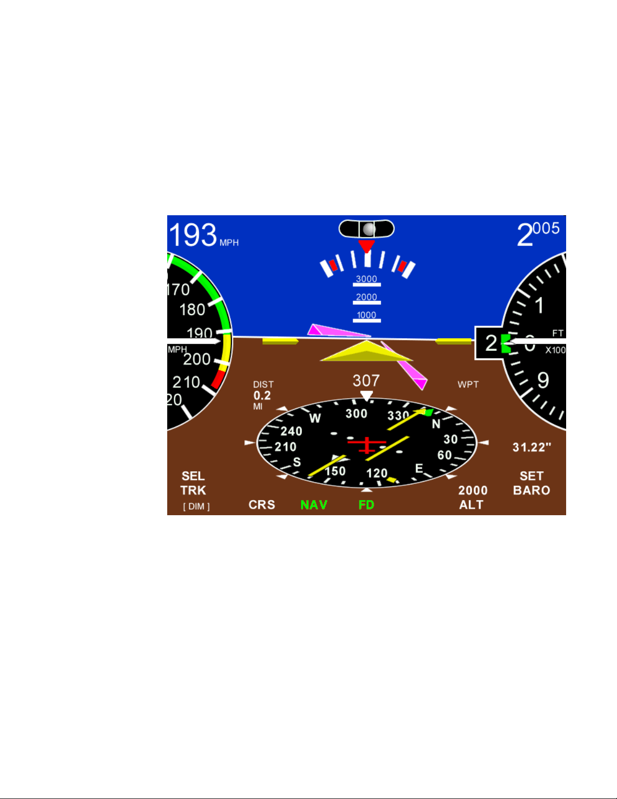
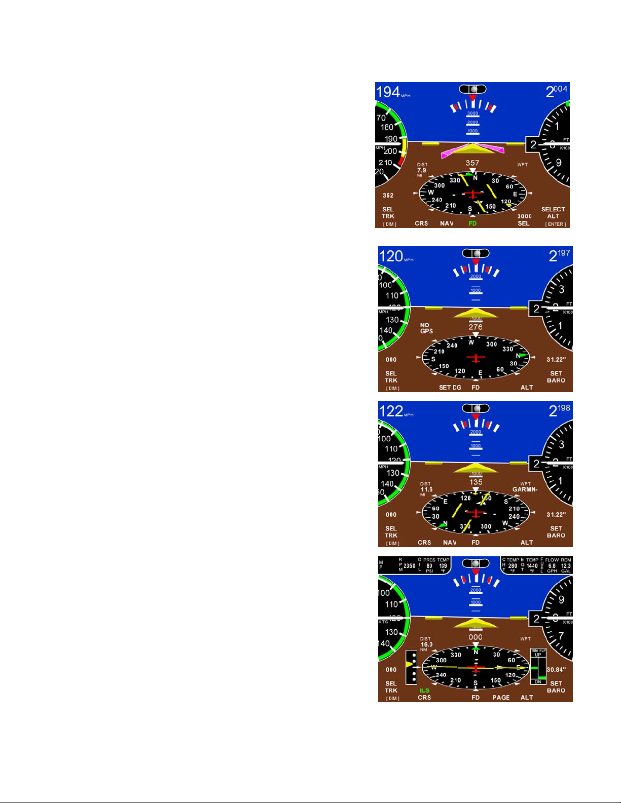
GPS INFORMATION
The HSI requires GPS NMEA information to function correctly.
If the primary serial connection and communication protocols
have been setup correctly, the EFIS screen will display NO GPS
FIX until the GPS unit has acquired satellites. Then the display
will show GPS/HSI information as shown. If not then the
Display will show NO GPS and only the DG will be operational.
When a flight plan has been entered into the GPS the HSI will
display a Course to the first way point. The deviation bar will
offset to show the aircraft present position compared to the
desired track. The yellow diamond bug shows bearing to
waypoint. Setting the HSI CRS pointer is accomplished by
pressing the soft key beneath CRS to enter the set up screen.
Rotation of the left knob selects the course.
SL 30 INFORMATION
If the serial wires are connected from a SL 30 NAV/COM. The
EFIS will have VOR or ILS above the CRS label. Press and
HOLD the button to display this information on the HSI.
TruTrak Flight Systems 5 EFIS Installation Manual
February 2009 8300-056 Rev B
Page 8
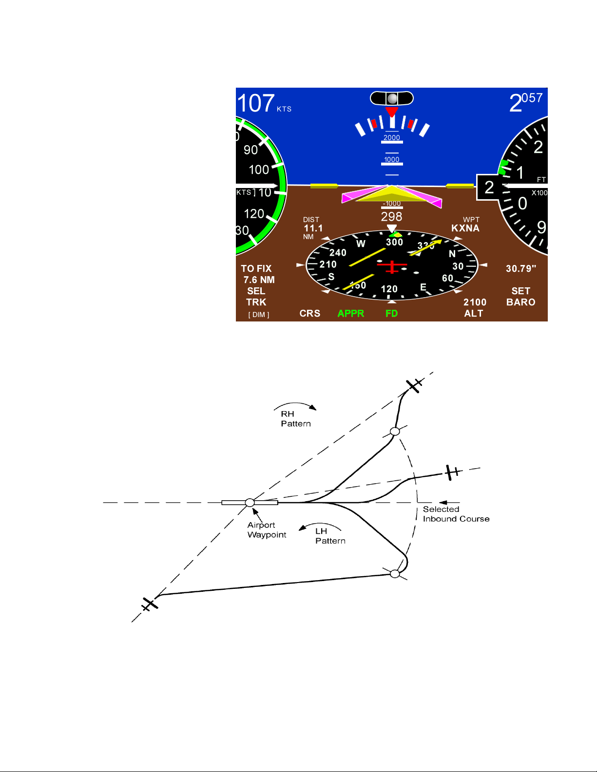
AUTOMATIC ARRIVAL TRANSITION
In an aircraft tracking a course
inbound to a destination airport, the
letters CRS will appear above the far
left soft key when the distance
becomes less than 30 miles. When
CRS is showing the autopilot can be
programmed to fly a transition from
the enroute arrival course to a
selected arrival course set into the
HSI. This is not intended to be used
in an IFR approach but instead as a
convenience for the low time pilot in
arriving at an un-familiar airport or
for the over loaded pilot in marginal
VFR weather.
To initiate the automatic
arrival mode, press CRS, select the
desired inbound runway course, and press APPR. The autopilot will now fly the entire arrival path to
the desired runway. An additional feature of the automatic arrival mode can be used to position the
aircraft according to the desired right or left hand pattern. After setting the inbound course press ENTER
instead of APPR to remain in track mode. Once the desired aircraft position is established, press CRS
then APPR to initiate the automatic arrival. This procedure works regardless of the direction of the
inbound course and that of the selected approach course to the airport.
PRESS CRS – SELECT COURSE – PRESS APPR
TruTrak Flight Systems 6 EFIS Installation Manual
February 2009 8300-056 Rev B
Page 9

SETUP SCREENS
To enter the setup screen the right knob must be pressed and held until the SETUP shows then press and
release the soft key below SETUP before releasing the right knob. This is the location that the STYLE,
ATT & ZERO, INFO, UNITS, BALL, ALERTS, SPEEDS, & SERIAL Baud rate are set at.
Press and release the right knob to return to the main screen.
STYLE
Select ether ROUND gauge or
RECT tape style airspeed and
altimeter gauges.
Press and release the right knob to
return to the SETUP screen if no
selection pressed.
ATT & ZERO
Click ATT on or off to show aircraft attitude indication on the EFIS
horizon. The attitude can be zeroed for different aircraft by clicking
the ZERO soft key button.
INFO
This button will display the information about all the components that
are connected to the EFIS communication buss, Serial numbers,
Software version, and Model type.
The LEFT KNOB must be clicked to return to the main page.
TruTrak Flight Systems 7 EFIS Installation Manual
February 2009 8300-056 Rev B
Page 10

UNITS
Under this button the UNIT of
Measure for the BARO ( IN HG,
MBAR) or DIST (NM, MI, KM)
readouts can be set.
BALL
After the EFIS is installation in the aircraft, center the ball by rotating
the right knob.
Press and release the right knob to return to the SETUP screen.
ALERTS
LOW AS
Setting the airspeed to 0 will disable
the warning.
When an airspeed is selected by the
right knob, the arrow on the airspeed
gauge will flash red at your selected
airspeed. The flight director bar, if
engaged, will flash red and drop to
indicate an airspeed increase is needed.
Press and release the right knob to return to the SETUP screen if no selection pressed.
TruTrak Flight Systems 8 EFIS Installation Manual
February 2009 8300-056 Rev B
Page 11

SPEEDS
VSO Bottom of the white arc. The stall speed or the
minimum steady flight speed in the landing configuration.
VS Bottom of the green arc.
minimum steady flight speed clean configuration.
The stall speed or the
VFE
Top of the white arc. Maximum flap extended
speed.
VNO
Top of the green arc. Maximum structural
cruise speed.
VNE
Red line, Top of yellow arc. Never exceed speed.
Press and release the right knob to return to the SETUP screen if no
selection pressed.
SERIAL
Select ether 4800 or 9600 Baud for correct GPS communications.
Press and release the right knob twice to return to the MAIN screen.
TruTrak Flight Systems 9 EFIS Installation Manual
February 2009 8300-056 Rev B
Page 12

ENGINE INFORMATION
If the Engine Data Module is installed, connecting the TCB A & B
will display engine information at the top of display. More detailed
information is available under the page button. You must return to the
MAIN page to enter the setup pages.
FLIGHT DIRECTOR
The magenta wings that come up when the FD button is pressed will
show the aircraft flight positioning to follow and maintain TRK, VSI,
NAV, etc commands. All the pilot has to do is keep the triangle in the
wings as they move to follow the commands the pilot commanded the
EFIS to perform. A change in TRK will command the wings to bank
in the direction to acquire the new TRK. (AS SHOWN) A command to
climb to a new altitude will cause the wings to move up on the
horizontal plane to acquire the new altitude. When there is not enough
airspeed to perform a climb. The FD wings will not rise above the
horizon.
EFIS SOFTWARE UPDATES
COMPACT FLASH SLOT
The EFIS software can be updated by inserting a Compact
Flash card (CE), with the face down, in the top slot on the
back. Software updates are available from TruTrak Then
apply power to the EFIS, monitor the screen. Follow the
instructions on the screen. When power is applied to the
EFIS again the new software will be installed. Confirm the
update by watching the display lower left side on startup
for the version number change or in the INFO page..
TruTrak Flight Systems 10 EFIS Installation Manual
February 2009 8300-056 Rev B
Page 13

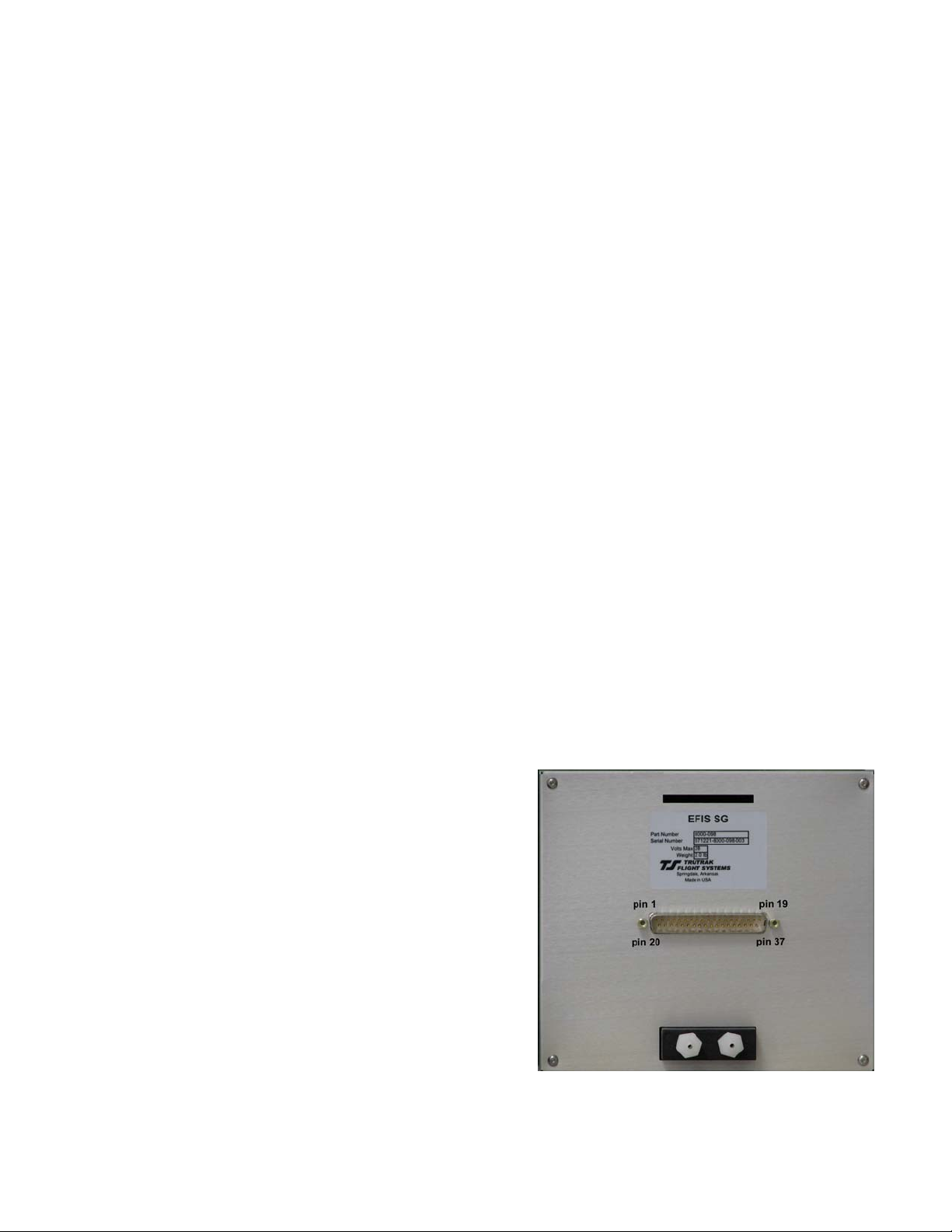
Electrical Pin-out
The table below provides a brief explanation of each pin function on the main 37-pin connector P101.
P101 EFIS Rear Connector (Viewed from rear of EFIS) or wire side of connector.
P101
Pin
Function Notes
1 Dedicated ground connection for Pitch Reverse Jumper.
2
Pitch Reverse Jumper
3 SL-30 RS-232 OUTPUT.
4 BUTTON DIMMER connection
5
NO CONNECTION
6
NO CONNECTION
7
ALERT
8
NO CONNECTION
9
10 Pitch Servo Torque Control. A signal from the autopilot to the pitch servo which sets the
amount of torque to be delivered by the servo.
11 Pitch Servo Trim Sensor. A signal from the pitch servo to the autopilot which indicates an
out-of-trim condition and its direction.
12 AIRCRAFT POWER (+12 to +28 V DC). The EFIS itself draws less than 3 ampere.
13 Audio signal Out. This pin may be wired to an unswitched input of an audio panel. The
autopilot uses various voice or tones to denote specific events (loss of GPSS, capture
Glideslope, etc). Volume is adjustable within a setup screen of the autopilot.
14
Pitch Servo control lines. These lines cause the stepping motor in the pitch servo to run in the
appropriate direction at the desired velocity. They are small-signal lines and do not have any
15
substantial current-carrying capability or require any special shielding. Connect to pitch servo
16
as shown on wiring diagram.
17
18
AOA
19 GROUND CONNECTION. Provide #20 AWG to common ground ing point.
Direction of servo arm / capstan rotation
EFIS autopilot only
EFIS autopilot only
Not used at this time
Not used at this time
EFIS autopilot only
EFIS autopilot only
EFIS autopilot only
Not used at this time
TruTrak Flight Systems 11 EFIS Installation Manual
February 2009 8300-056 Rev B
Page 14

Autopilot Rear Connections to P101 (Continued)
P101
Function Notes
Pin
20 Control Wheel Switch. Connect as shown in wiring diagram to a SPST momentary sw itch
EFIS autopilot only
located remotely to the autopilot for convenient engage/disengage function.
21
FLAP SW.
22
ALT RS-232 Output
23
SPARE SWT
24
No Connection
25 PRIMARY SERIAL INPUT. Baud rate selectable 1200, 2400, 4800 or 9600 baud.
Not used at this time
Not used at this time
Not used at this time
Automatically decodes NMEA-0183, Garmin Aviation Format, or Apollo/UPSAT MovingMap or GPSS format. Provides directional reference to the autopilot.
26
ARINC-A
27
ARINC-B
28 Roll Servo Torque Control. A signal from the autopilot to the roll (aileron) servo which sets
Digital differential signals from Garmin, Sierra, or other panel-mount receiver
which provide directional steering commands (GPSS) to autopilot
EFIS autopilot only
EFIS autopilot only
the amount of torque to be delivered by the servo.
29
30
SL 30 RS232 IN
31
AP Power
Roll (aileron) Servo control lines. These lines cause the stepping motor in the roll servo to run
in the appropriate direction at the desired velocity. They are small-signal lines and do not have
any substantial current-carrying capability or require any special shield ing. Connect to roll
32
servo as shown on wiring diagram.
33
34
35
Wiring to roll servo J201
Direction of servo arm / capstan rotation
(as viewed from face of the servo body)
J101 Pin 32 Pin 33
for RIGHT aileron
Not used at this time
No Connection
EFIS autopilot only
Reverse servo
direction if necessary
by swapping wires on
pin 32 and 33. See
note 3 on wiring
diagram.
Standard J201-4 J201-5 Servo CCW (counter-clockwise) Î RIGHT
Reversed J201-5 J201-4 Servo CW (clockwise) Î RIGHT
36
37
TCB-B
TCB-A
Not used at this time
Not used at this time
EFIS
P1 pins
RS 232 25 11 Data out Data out Blue wire Blue wire Blue wire Blue wire Blue wire Blue wire Data out
ARINC
A
ARINC
B
EFIS
P1 pins
RS 232 25 19 19 19 5 / 22 P1- 22 56 56
ARINC
A
ARINC
B
King
KMD 150
26 N/C N/C N/C N/C N/C N/C N/C N/C N/C N/C
27 N/C N/C N/C N/C N/C N/C N/C N/C N/C N/C
Garmin 155XL Garmin 200XL Garmin 300XL Garmin GX 50-65 Garmin GNS 480 Garmin 430
26 16 16 16 N/C P5 - 4 46 46
27 15 15 15 N/C P5 - 24 47 47
Garmin III Garmin 92 Garmin 195 Garmin 196 Garmin 295 Garmin 296 Garmin 396 Garmin 496 AvMap
EKP IV
Garmin 530
P4001
P5001
EFIS or
EFIS AP SERIES
ALL
CURRENT DRAW
LOW BRIGHT
1.07 Amps @ 12v
0.65 Amps @ 24v
CURRENT DRAW
HIGH BRIGHT
2.02 Amps @ 12 v
1.15 Amps @ 24v
WEIGHT
2.33 lbs High bright
6.375W x 5.75H x 3.625D
1.95 lbs Low bright
DIMENSIONS
Behind panel
TruTrak Flight Systems 12 EFIS Installation Manual
February 2009 8300-056 Rev B
Page 15

EFIS Basic Wiring Diagram
The connector ( P1) view is as if you are looking at the connector on the unit. This is the same view of the wire connector on
the wire side for pin placement.
NOTE: Some pins are not used at this time, see pin out page 11 & 12.
TruTrak Flight Systems 13 EFIS Installation Manual
February 2009 8300-056 Rev B
Page 16

TruTrak Flight Systems 14 EFIS Installation Manual
February 2009 8300-056 Rev B
Page 17

TruTrak Flight Systems 15 EFIS Installation Manual
February 2009 8300-056 Rev B
Page 18

TruTrak Flight Systems 16 EFIS Installation Manual
February 2009 8300-056 Rev B
Page 19

TruTrak Flight Systems 17 EFIS Installation Manual
February 2009 8300-056 Rev B
Page 20

TruTrak Flight Systems 18 EFIS Installation Manual
February 2009 8300-056 Rev B
Page 21

EFIS Pilot’s Guide
Button labels – White - mode is OFF, Green - mode is ON
Click – Momentarily push and release any knob or button
Press – Push and hold any knob or button for 2 seconds and release
Enter – Click knob labeled
[ Enter ]
Basic Operation
Barometer adjust – Rotate right knob
Track bug adjust – Rotate left knob
Altimeter bug adjust – Click ALT button, bug will synchronize to nearest 100 feet
Rotate right knob to select new altitude (Depress knob for 100 ft resolution)
Click
[ Enter ]
Altimeter bug cancel – Click ALT button
Dimmer function – Click left knob to enter setup mode Rotate left knob to set desired brightness
Click
[ Enter ]
Nav mode – Click NAV button
Nav mode cancel – Click NAV button or rotate left knob (Track bug adjust)
Flight Director Operation
Flight Director on / off – Press FD button – on,
Press FD button – off
Track select – Rotate left knob
Nav mode – Click NAV button
Nav mode cancel – Click NAV button or rotate left knob (Track select)
Altitude select – Click ALT button, bug will synchronize to nearest 100 feet
Rotate right knob to select new altitude (Depress knob for 100 ft resolution)
Click
[ Enter ] (VS is fixed at +/- 500 FPM)
Barometer adjust – Rotate right knob
Dimmer function – Click left knob to enter setup mode, Rotate left knob to set desired brightness
Click
[ Enter ]
Arrival Transition
(Note: Operation is the same regardless of FD being on or off)
Arrival Transition – Click CRS
Rotate left knob to set HSI course pointer to selected runway direction
Click APPR
TruTrak Flight Systems 19 EFIS Installation Manual
February 2009 8300-056 Rev B
Page 22

TruTrak Flight Systems No Penalty Upgrade Policy
As the product line continues to grow, it becomes increasingly difficult to maintain a simple upgrade policy. We do
want to reward our repeat customers by allowing a lower cost upgrade from one system to another; however we
are not able to offer this across the board on all products. If you are considering an upgrade, please call and we
will give you a quote on what this would cost. Many products that we sell today are upgradeable for only the
difference in system price. Because we continually strive to have the most up to date products possible, we
occasionally have to discontinue products. We will continue to offer discounted upgrades even for our discontinued
products.
TruTrak Flight Systems 20 EFIS Installation Manual
February 2009 8300-056 Rev B
Page 23

RETURN MERCHANDISE POLICY AND PROCEDURE
Under no circumstances should products be returned to TruTrak without first obtaining a Return of Merchandise
Authorization number (RMA #) from TruTrak. An RMA# may be obtained by contacting us at 866-878-8725.
Products that do not have an RMA # will not be processed.
Please include documentation stating the reason for the return and describing any symptoms, failure modes,
suspected causes of damage, diagnostics performed, data collected, etc.
Product(s) should be packaged in their original shipping containers. In lieu of this, they should be very carefully
packaged in containers suitable to protect them during transit. For your protection, items should be insured for the
full value. Note that damage caused during shipping will not be repaired under warranty.
The outside of the box must be clearly marked with the RMA # issued by TruTrak and the RMA # must also be
noted on the return documents.
Products will be returned to the customer at no charge via FedEx Ground or UPS Ground. If customer requests
expedited shipping (2
number.
INTERNATIONAL SHIPMENTS:
Trutrak sends all International shipments with an insurance value on all products. Trutrak pays for shipping only.
The customer is responsible for any and all additional fees, duties, taxes associated with the shipment.
When sending products to Trutrak for repair or otherwise please be advised that the customer is responsible for all
charges and fees associated with shipment. For your protection, items should be insured for the full value.
Trutrak states on all product returns “WARRANTY REPAIR AT NO CHARGE TO CUSTOMER. A COMMERCIAL
INVOICE VALUE OF $___ GIVEN FOR INSURANCE PURPOSE S ONLY”
Please keep in mind that your government or another entity in your country may impose a charge for custom and/or
brokerage fees, duties and taxes on items received from the US. These charges do not originate from our company nor do
we benefit from them in any way. You are responsible for payment of all custom and brokerage fees, duties and taxes that
may be imposed when these goods are imported into your country.
Send ALL return shipments to:
TruTrak Flight Systems, Inc., 1500 South Old Missouri Road, Springdale, AR 72764 USA
Attention: Returns Dept. RMA#
Warranty On TruTrak Flight Systems Products
We here at TruTrak Flight Systems know how important it is to feel as though the customer is purchasing a product
that the manufacturer is going to stand behind. For this reason we want offer more than the basic one year warranty
that is standard to this industry. The warranty on all TruTrak products will be three years from the date of
purchase. Abuse and misuse of a product are not covered under this warranty. Modification to a product may void
the warranty, as well as carry a penalty when upgrading to another product. This three year warranty will be for all
products except the Pictorial Turn & Bank, which will continue to have a warranty of one year from the date of
purchase.
nd
Day or Overnight) they will be charged the shipping cost and must supply a credit card
TruTrak Flight Systems 21 EFIS Installation Manual
February 2009 8300-056 Rev B
Page 24

TruTrak Flight Systems, Inc.
1500 S. Old Missouri Rd.
Springdale AR 72764
(479) 751-0250
FAX (479) 751-3397
www.trutrakap.com
 Loading...