

Page 1
Quick Reference Guide
CT-UTVM
Page 2
CT-UTVM QRG EN
About This
The CT-UTVM Quick Reference Guide (QRG) has basic product
information on how to use your new television mount. See
Disclaimer
Read ALL the Safety Notes in this document before installing, using, or
maintaining this product. CHAUVET® may change this QRG at any time
Safety Notes
• Carefully inspect the moun t ing plate, arms, a nd connecting hardware.
DO NOT use a CT-UTVM that has been dropped.
CAUTION: T he maximum load capacity for the CT-UTVM is 200
Contact
Outside the U.S., United Kingdom, or Ireland, contact your distributor to
for
What Is
Included
• CT-UTVM
• Warranty Card
Not
The following common items are not included, but are suggested in t he
Be su re to follow all instructions and cautionary statements that may
Guide
www.chauvettrusst.com for the lates t in forma tion on th e CT-UTVM.
.
• Only trained people should assemble the CT-UTVM.
• Be sure to determine w hat kind of arms are required to carr y the TV for
each job.
• DO NOT use the CT-UTVM for loa d s th at ex ceed the maximums
provided in this QRG.
• DO NOT use the CT-UTVM if any sections or joints are cra cked or
appear damaged in any way.
• ONLY hang on horizontal rungs of trusses. D i agonal and vertical r ungs
are not design ed to bear weight.
• DO NOT use the CT-UTVM if the arm s, mounting plate or connecting
hardware are bent.
• Install the CT -UTVM properly using all necessary parts.
• DO NOT drag the CT-UTVM over s urfaces or other TV moun ts. If you
cannot carry the C T-UTVM properly alone, make sure someone else
can h e lp you.
•
lbs (90.7 kg). DO NOT exceed this number.
Supported television sizes are 26–50 in (66–127 cm).
request support or return a product. Visit www.chauvettrusst.com
contact information.
• Connecting Hardware
Included
assembly and mounting of the CT-UTVM.
• Drill
• Drill Bit 3 mm
• Masonry Drill Bit 12 mm
• Hammer
• Pencil
accompany any additional items you obtain.
2
• Quick Reference Guide
• Phillips Screwdriver
• Stud Finder
• M6 x 76 mm Hex Wood Screws (4)
• M6 He x Wrench
Page 3
EN CT-UTVM QRG
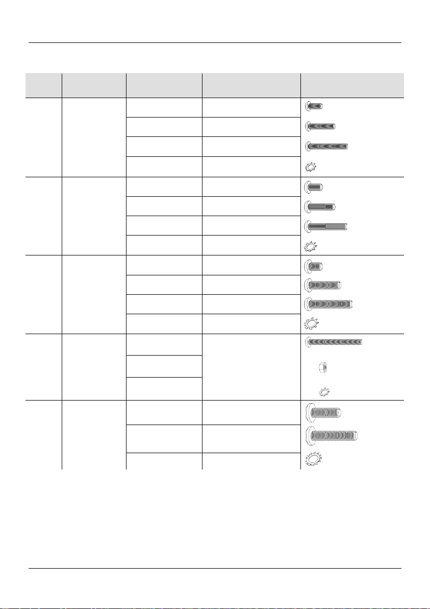
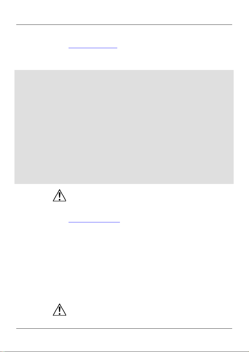
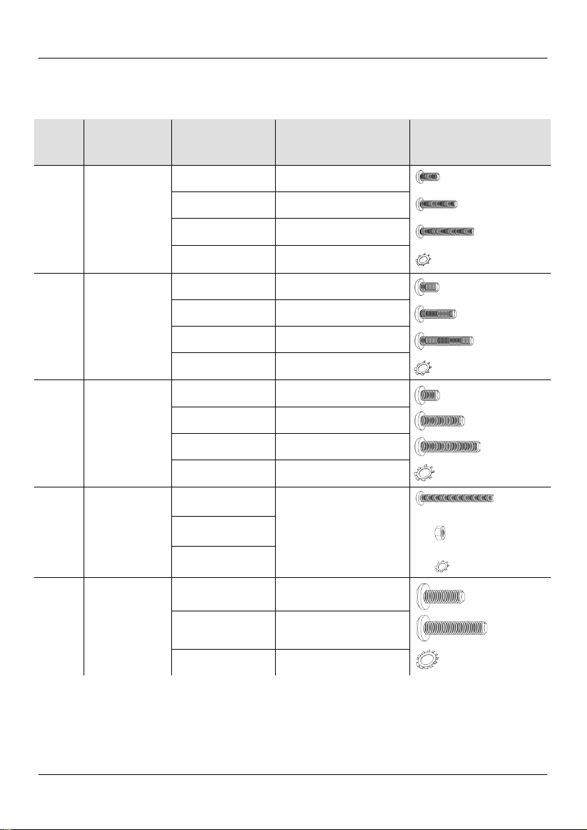
Parts List Including Connecting Hardware
Hardware
for Small TV
(M4 Size Bolt s)
4 Phillips bolts
M4 x 1 0 mm
Short M4 bolts for flat
telev ision back
4 Phillips bolts
M4 x 20 mm
Medium M4 bol ts for
recessed television back
4 Phillips bolts
M4 x 30 mm
Long M4 bolts for recess ed
telev ision back
Lock washers for M4 bolts
Hardware
for Small TV
(M5 Size Bolt s)
4 Phillips bolts
M5 x 1 0 mm
Short M5 bolts for flat
telev ision back
4 Phillips bolts
M5 x 20 mm
Medium M5 bol ts for
recessed television back
4 Phillips bolts
M5 x 30 mm
Long M5 bolts for recess ed
telev ision back
Lock washers for M5 bolts
Hardware
for
(M6 Size Bolt s)
4 Phillips bolts
M6 x 1 0 mm
Short M6 bolts for flat
telev ision back
4 Phillips bolts
M6 x 2 5 mm
Medium M6 bol ts for
recessed television back
4 Phillips bolts
M6 x 35 mm
Long M6 bolts for recess ed
telev ision back
Lock washers for M6 bolts
Hardware fo r
Extension Arm s
8 Phillips bolts
M5 x 50 mm
Har d war e f o r at t ac h ing t h e
extension arms to the arms
Hardware
for Large TV
(M8 Size Bolt s)
Medium M8 bol ts for
recessed television back
Long M8 bolts for recess ed
telev ision back
Lock washers for M8 bolts
Bag
Number
Bag Contents/
Parts
Quantities and
Dimensions
Description Diagram
1
2
3
4
5
Large TV
4 M4 lock wash ers
4 M5 lock wash ers
4 M6 lock washers
8 M5 lock wash ers
8 M5 hex nuts
4 Phillips bolts
M8 x 25 mm
4 Phillips bolts
M8 x 40 mm
4 M8 lock wash ers
3
Page 4
CT-UTVM QRG EN
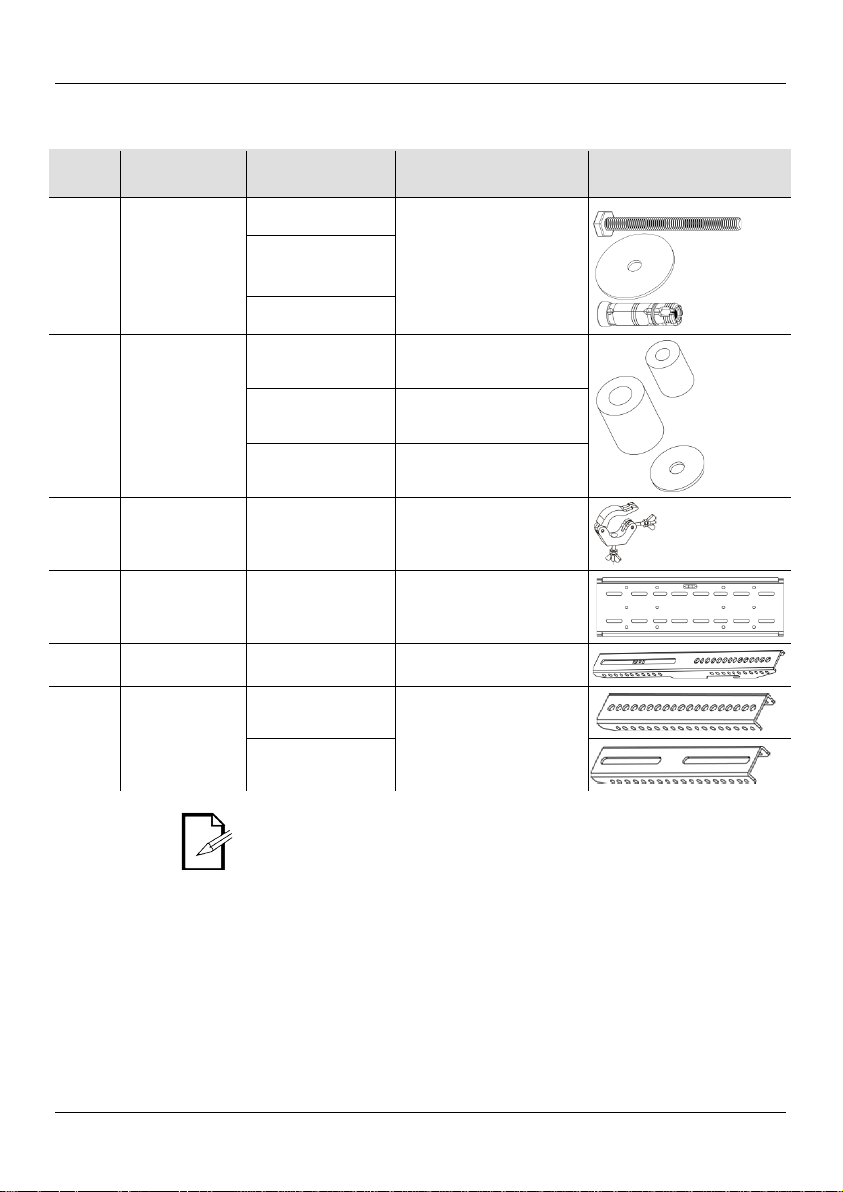
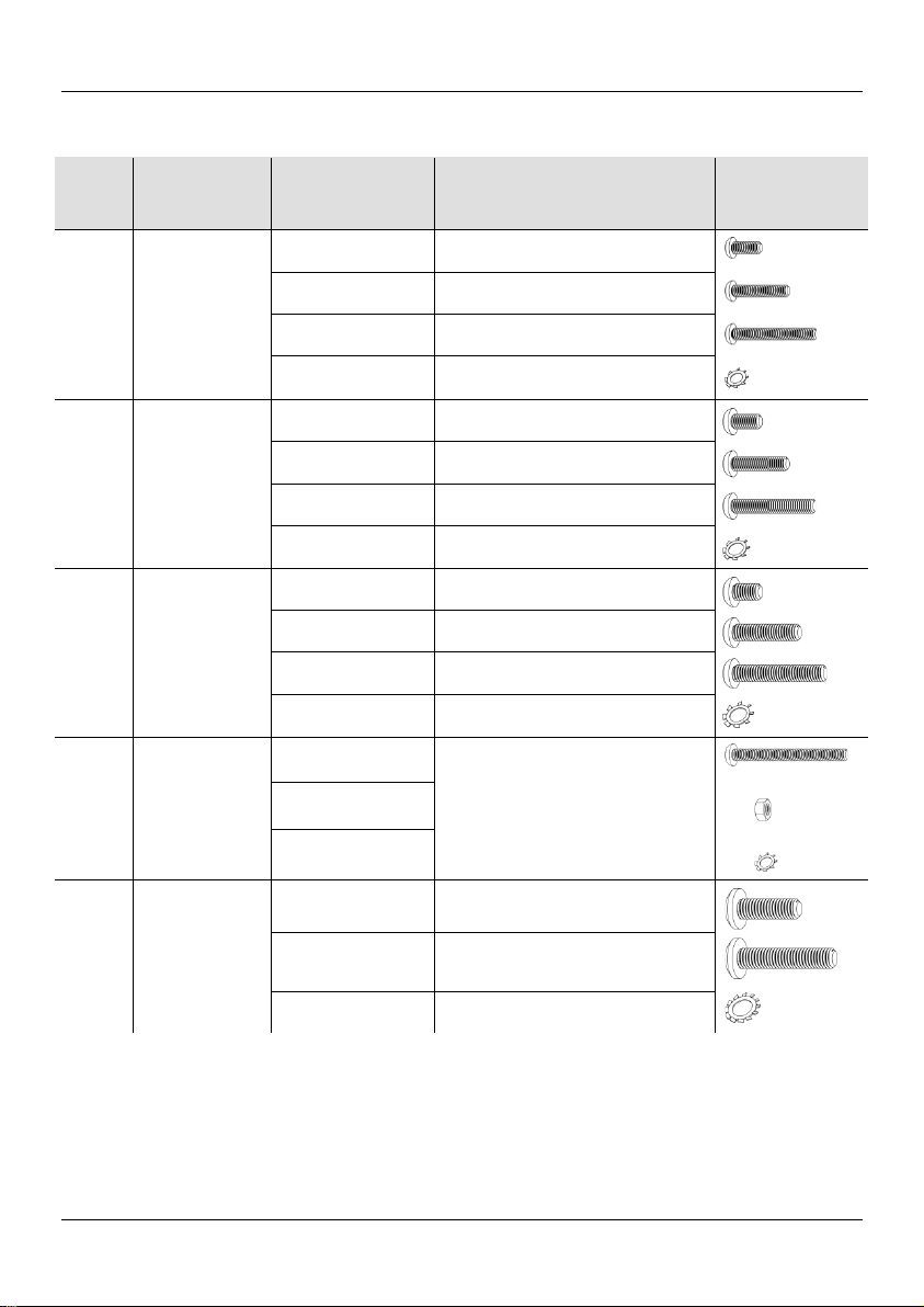
Parts List Including Connecting Hardware (cont.)
Hardware fo r
Wall Mou n tin g
6 hex bolts
M6 x 70 mm
6 M6 concrete
anchors
Spacers and
Washers
Small spacer s for recessed
Larg e spacers fo r recessed
Mounting
Clamps
Moun ting Plate
Arms
Arms to attach to th e back
Extension Arm s
To Begin
Unpack your CT-UTVM and make sure you have received all parts in
good condition. If the box or contents appear damaged, notify the
Product
Description
Bag
Number
Bag Contents/
Parts
Quantities and
Dimensions
Description Diagram
6
7
N/A
N/A
N/A
N/A
6 washers
2 arms
M6
4 spacers
M5
4 spacers
M8
4 washers
M5
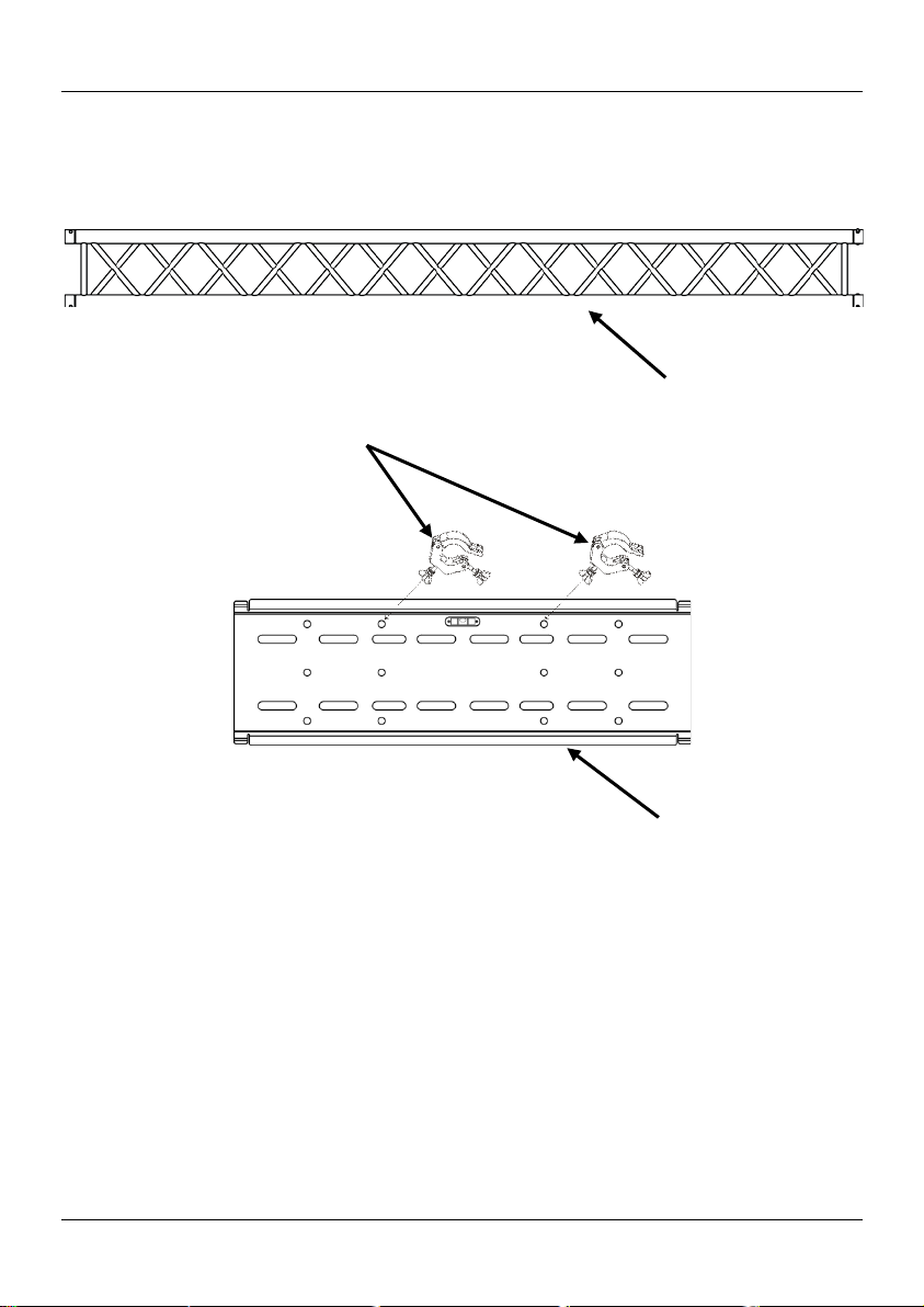
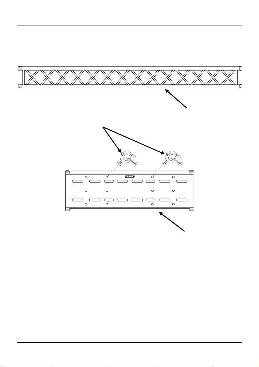
2 clamps Clamps for truss mounting
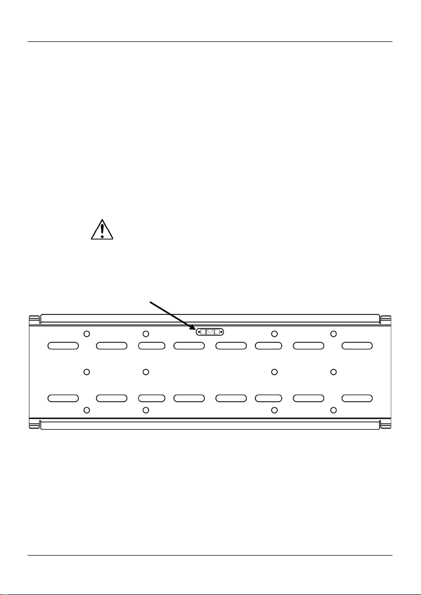
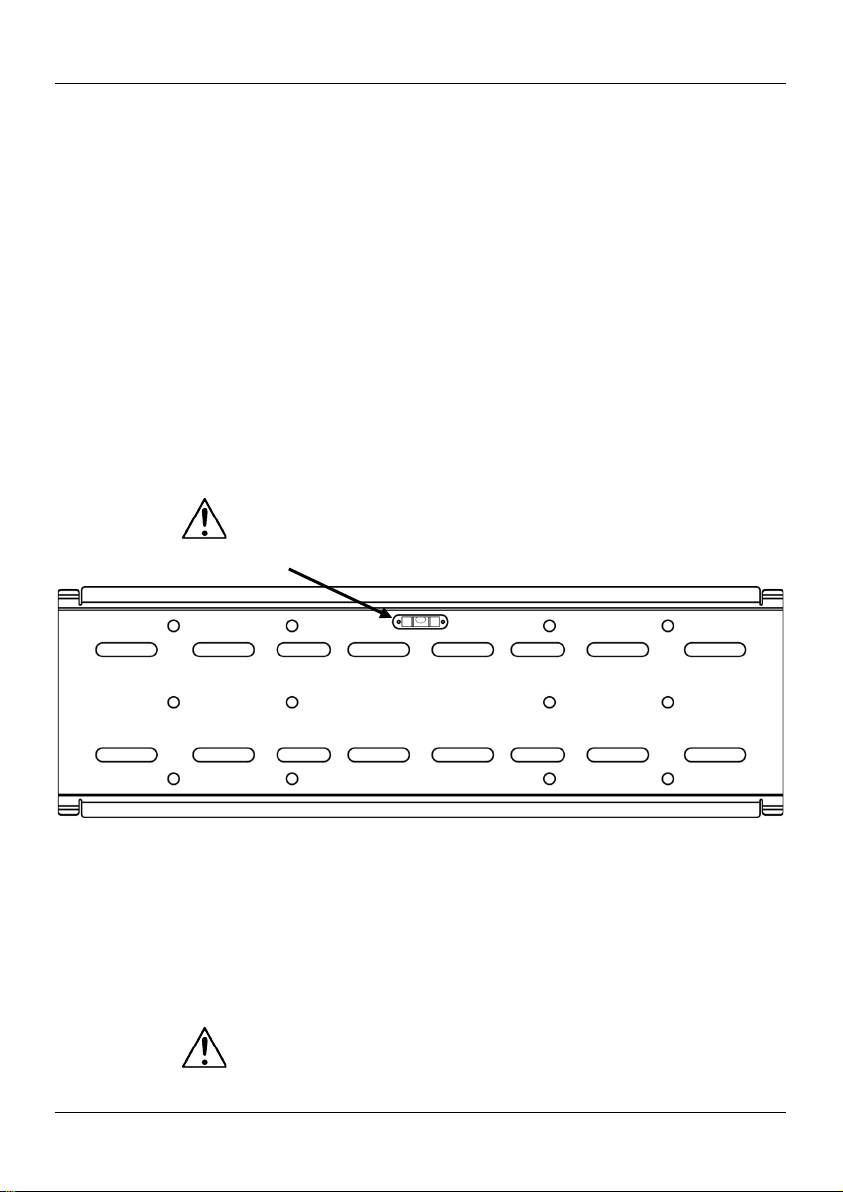
1 mountin g plate
27.2 x 0.6 x 8.6 in
(690 x 15 x 219 m m)
2 upper extension
arms
2 lower extension
arms
Har d war e f o r attaching the
mou n t i n g plat e on to a
cement wall
telev ision back
telev ision back
Washers
Mounting plate with
built-in bubble level
of the television
Extensi on arms used onl y if
the arms do not line up with
the holes in the back of the
television
Par ts diagram s are for ill ustra t ive p urposes only.
distributor immediately, not CHAUVET®.
The CT-UTVM is a universal television mount desig n e d to fit TRU S S T ®
and other truss systems.
4
Page 5
EN CT-UTVM QRG
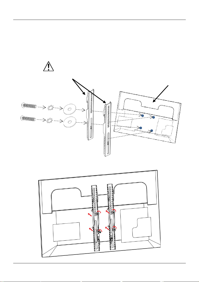
Flat-backed
1. Determine that t he TV has a fl at back, and not a recessed back.
Note : Do not over-tighten.
Arms
Lock
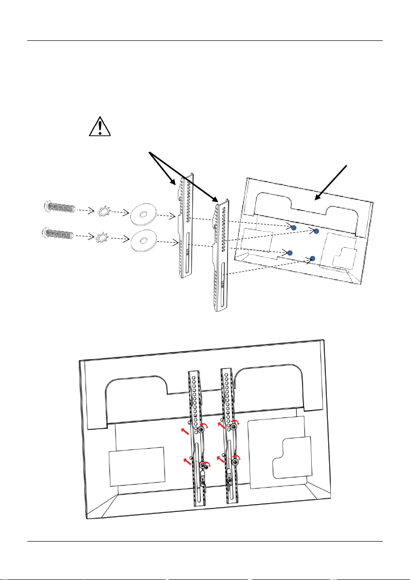
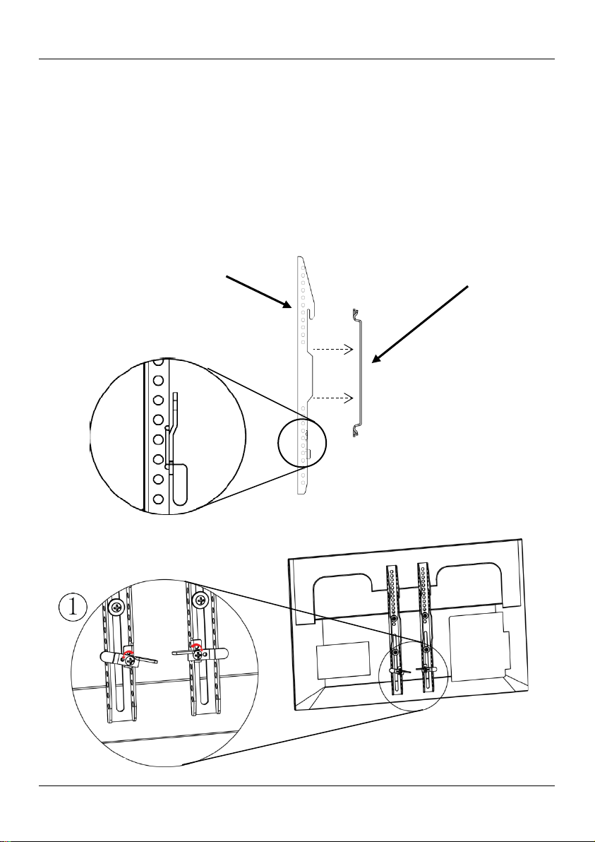
Attaching the Arms to the Television
Television
2. Attach both arms to the TV using the enclosed bolts, lock washers
(select prope r sizes from B ag 1, 2, 3, or 5), and washers (Bag 7) .
3. Tighten bol ts snugly.
Use 2 hardware assemblies for each arm.
Bolt
Washer
Washer
Note: The position of attachment point may vary from TV to TV.
Back of TV
5
Page 6
CT-UTVM QRG EN
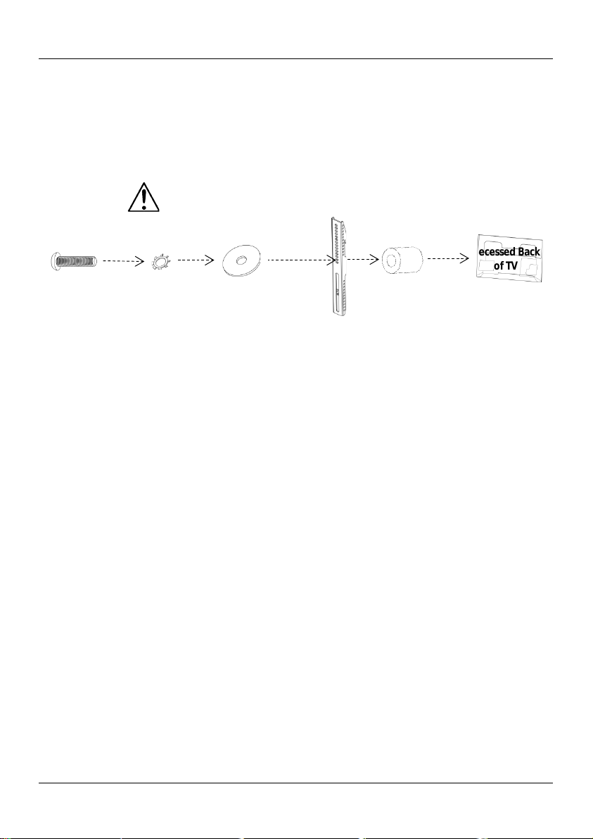
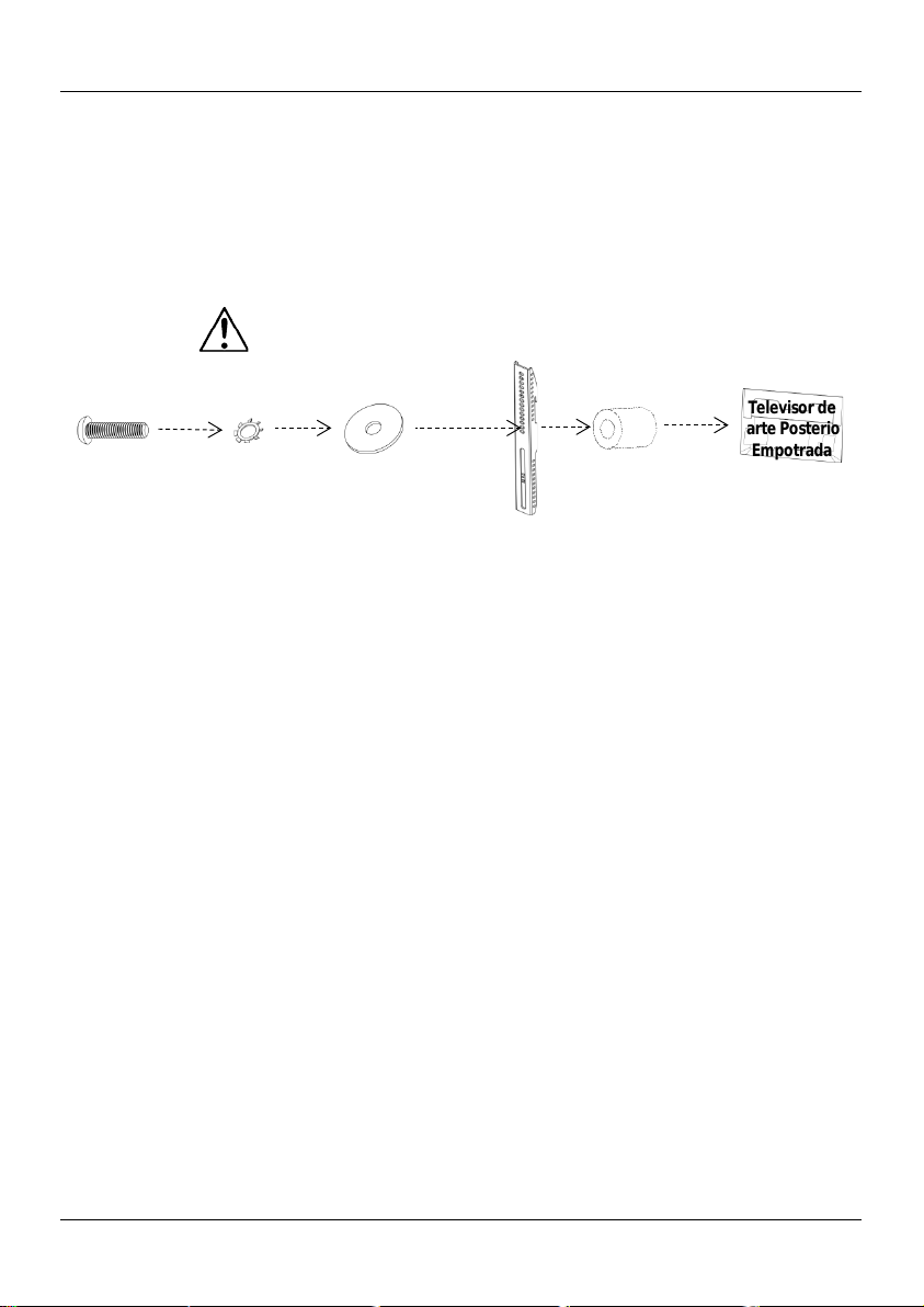
Recessed-back
1. Determ ine that the TV has a recessed back, and not a f lat back.
Note: Do not over-tighten.
Spacer
Recessed Back
of TV
Attaching the Arms to the Television (cont.)
Television
2. Attach both arms to the TV using the enclosed bolts, lock washers
(select prope r sizes from B ag 1, 2, 3, or 5), and washers (Bag 7) .
A spacer (Bag 7) goes between the arm and the television.
3. Tighten bol ts snugly.
Use 2 hardware assemblies for each arm.
Bolt
Lock
Washer
Washer
Note: The position of attachment point may vary from TV to TV.
Arm
6
Page 7
EN CT-UTVM QRG
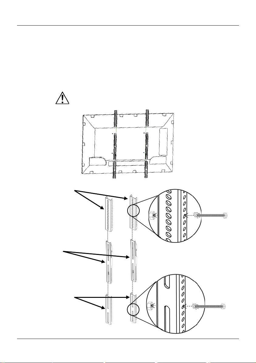
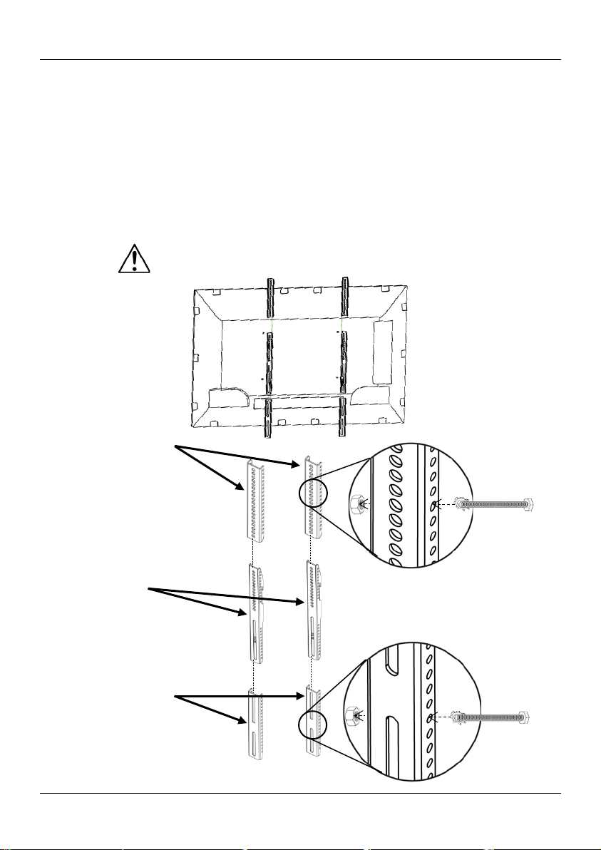
If th e holes in the arms do not line up with t he holes in the back of t he
using the enclosed
Note: Use 2 hardware assemblies for each lower extension arm.
Arms
Attach extension arms
Attaching the Extension Arms to the Arms
telev ision, attach th e e xtension arms as follows:
1. Attach the upper extension arms to the top of t he arms
bolts, lock w ashe r s, and hex nuts (Ba g 4) through the side holes.
Note: Use 2 hardware assemblies for each upper exten sion arm.
2. Attach the lower extension arms to the bottom of the ar m s usin g the
enclosed bolts, lock washers, and hex nuts (Bag 4) through the side holes.
Attach all 4 extensio n arms to the arms in the same manner.
Upper Extension Arms
Lower Extension Arms
through the side holes
7
Page 8
CT-UTVM QRG EN
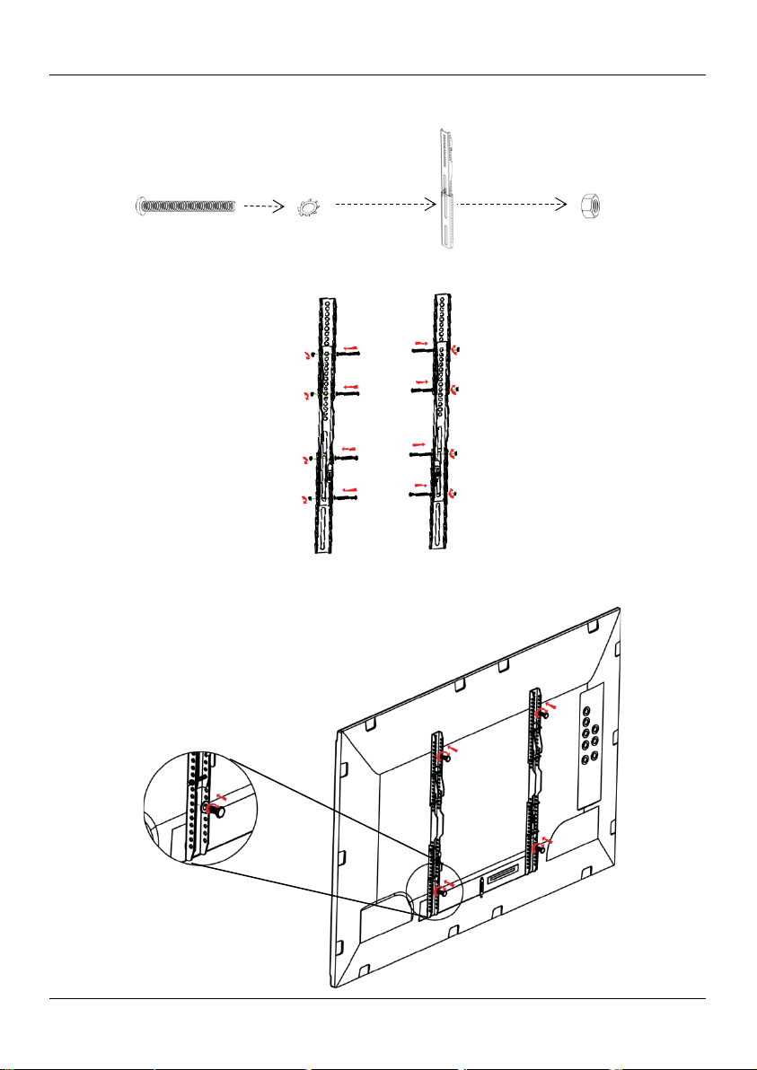
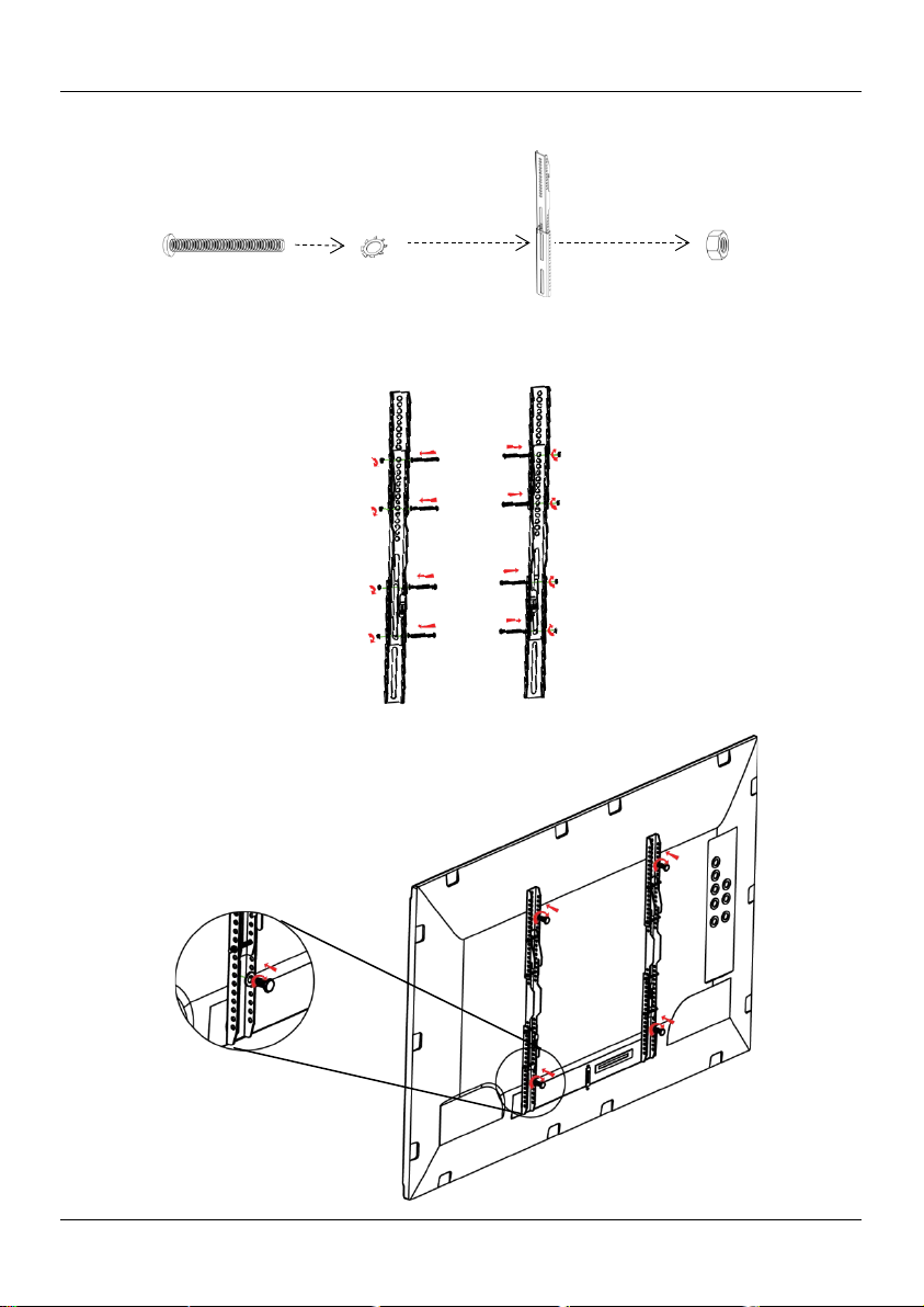
Note: Use 2 hardware assemblies as shown for each extension arm.
Extension
Arm
Hex Nut
Attach the arm/extension arm assemblies to the TV
Attaching the Extension Arms to the Arms (cont.)
as you would the arms without the extensions.
Bolt
Lock Washer
Arm
8
Page 9
EN CT-UTVM QRG
TRUSST® (or other truss)
Mounting Plate
Note: The placement of the clamps depends on the size of the truss.
Trus s Mounting the Television - Overview
The various positions of the holes are appropriat e for this purpose.
Mounting
Clamps
(enclosed)
9
Page 10

CT-UTVM QRG EN
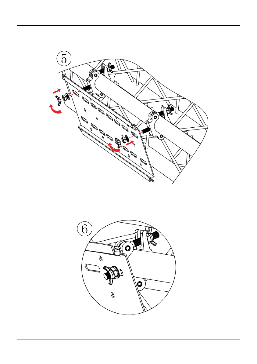
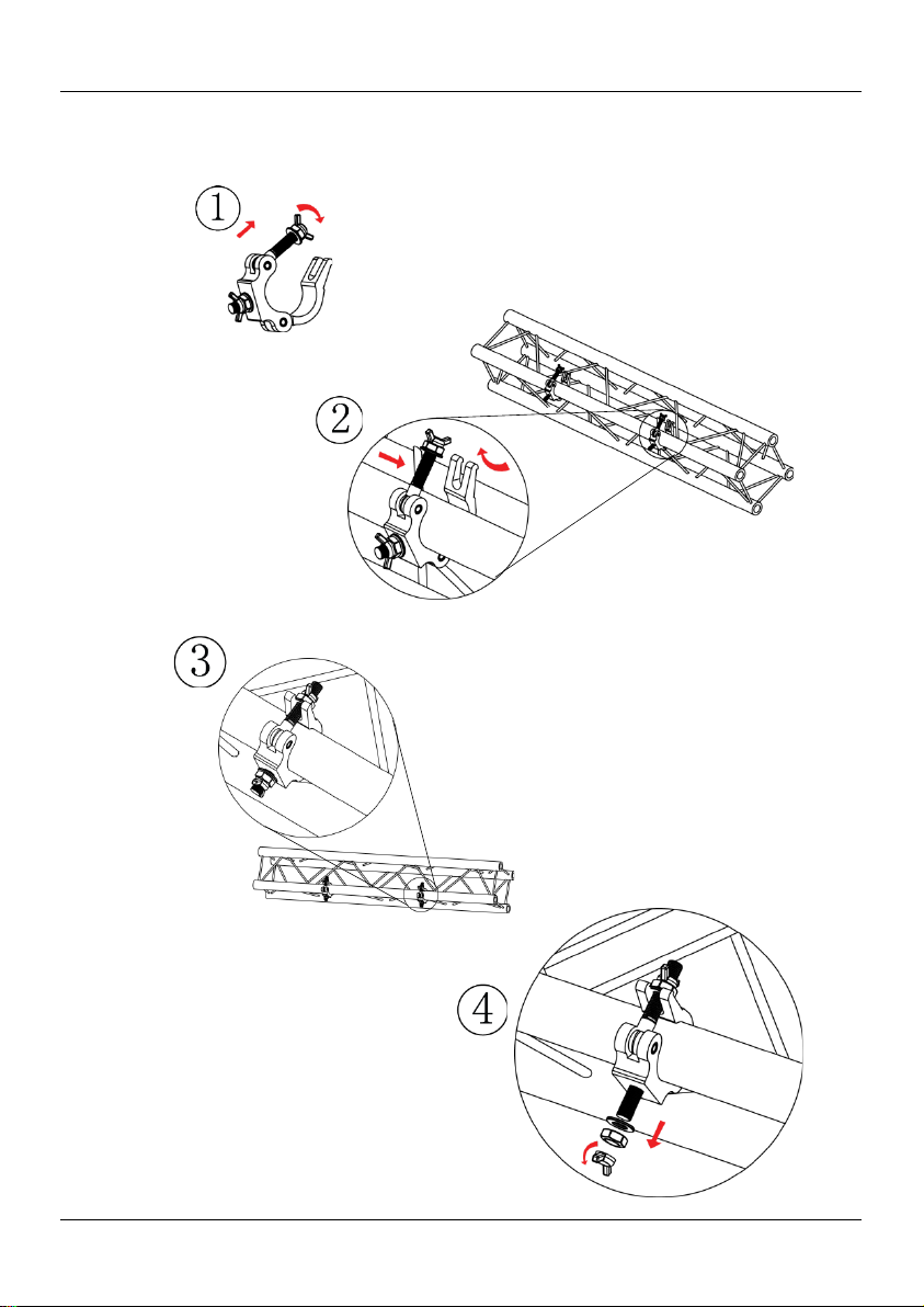
Truss Mounting the Television – Step-by-Step Detailed Views
10
Page 11
EN CT-UTVM QRG
Truss Mounting the Television – Step-by-Step Detailed Views (cont.)
11
Page 12
CT-UTVM QRG EN
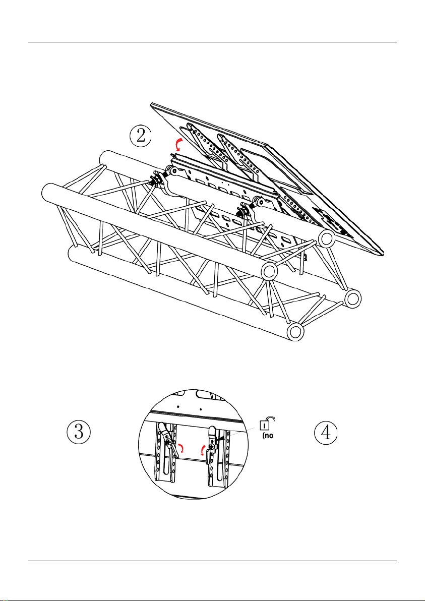
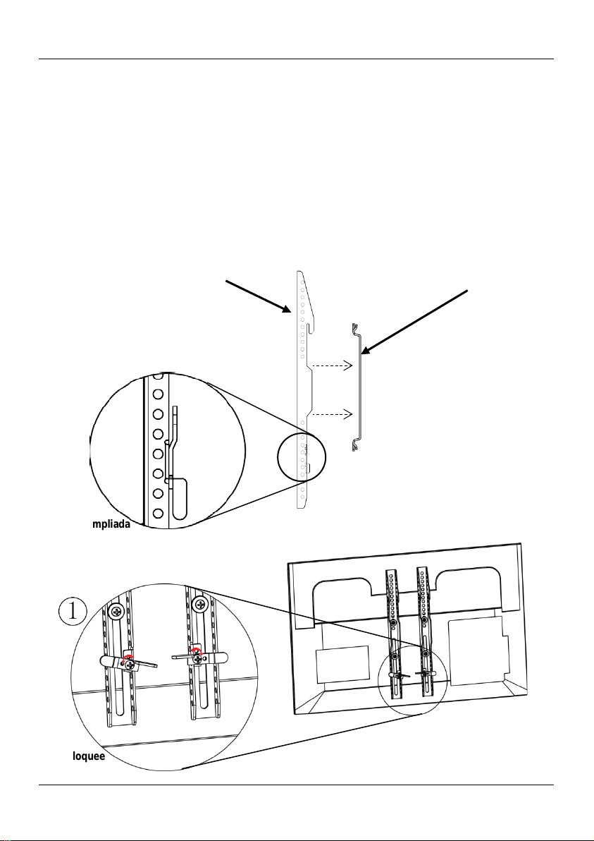
Once you properly attach the arms to the TV and properly mount the
1. Unlock the arms by pushing up the latch on the arms.
into the latch.
Latch Close-up
Views
Side View
Back of TV
Mounting the Television onto the Mounting Plate
mount ing pl ate to TR USST® ( or other t russ), you can t hen mount the TV
onto T RUSST®.
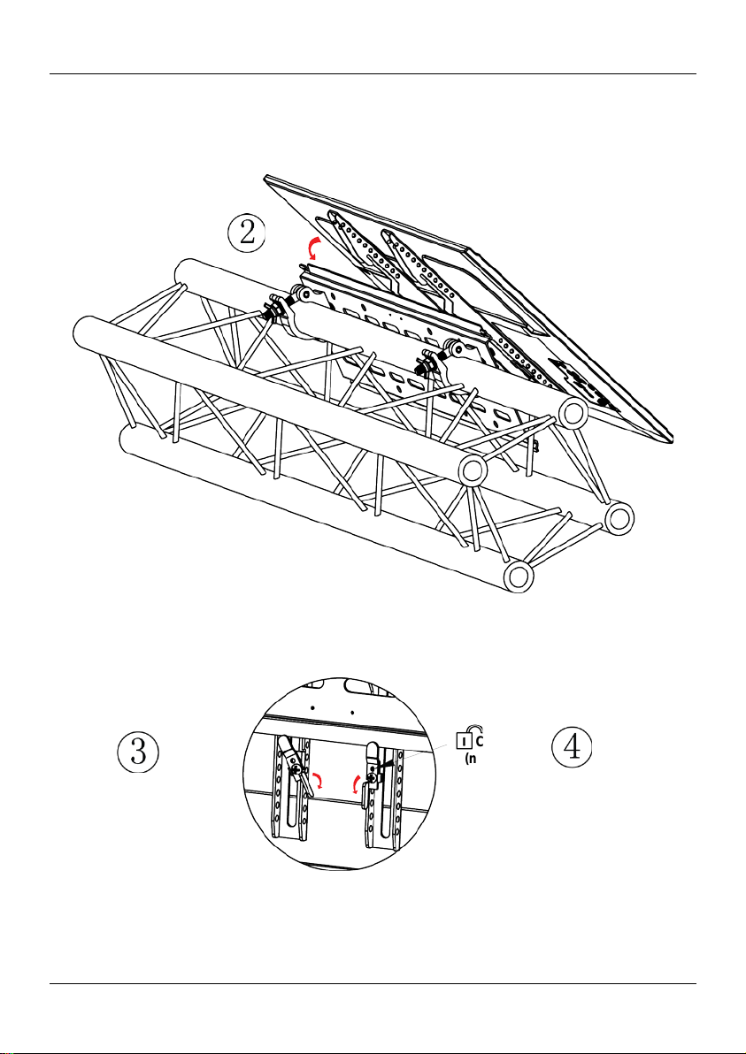
2. Place the arms on the upper lip of the mounting plate.
Note: You might need more than one person to lift the TV.
3. Lock the arms under the b ot tom lip of the moun t ing plate b y push i ng
down the latch on the arms . Do thi s for both arms.
4. To padlock the TV to the mounting plate, insert a padlock (not included)
Unlock Latches
Arm
Mounting Plate
12
Page 13
EN CT-UTVM QRG
Lock Latches
Mounting the Tel evision onto the Mounting Pl ate (cont.)
Padlock
(not included)
13
Page 14
CT-UTVM QRG EN
Wall Mounting
You can mount the TV onto the wall by first attaching the mounting plate to
Wall Mount
1. On the wall, locate 2 wooden studs within the widt h of the mounting
plate.
Attach the mounting plate to at least 2 wooden studs and use all 4
Do not over-tighten.
the wall.
plate.
2. Line up and mark one of the t op left holes of the mounting pl ate t o the
center of the left wooden stud at the desired h eight .
3. Drill a pilot hole where you made the top left mark.
4. Drive 1 hex screw (not included) and 1 washer (Ba g 6) through the top
lef t hole i n the mounting pl ate and through t he drywall i nto the center of
the stud.
5. Using the bui lt-in bubble level, adjust the mounting plate until it is lev e l.
6. Mark t he desired locat ion for the 3 r emaining holes i n the center of the 2
studs you ident ifi ed.
7. Drill pilot holes for the 3 remaini ng hol es.
8. Drive i n 3 additional he x scre ws an d w asher s to secure the mounting
screws when attaching the mounting plate to drywall.
Built-in Bubble Level
14
Page 15

EN CT-UTVM QRG
Wall Mounting (co nt.)
Concrete Wall
1. On the con crete wal l, pl ace the mountin g plate a t the de s ired heigh t .
washers (Bag 6) through the mounting plate and into eac h anchor.
Use all 6 bolts when attaching the mounting plate to the concrete wall.
Do not over-tighten.
2. Using the bui lt-in bubble level, adjust the mounting plate and mark 6
holes.
3. Place the mounting pl ate asi de an d drill 6 hol es into t he concret e, whe re
marked, and insert 6 concrete anchors (Ba g 6) into the holes.
4. Attach the mounting plate to the concrete wall by dri ving 6 h ex bolts and
15
Page 16
CT-UTVM GRR ES
Acerca de
La Guía de Referencia Rápida (GRR) del CT-UTVM contiene información
básica sobre cómo usar su nuevo soporte de televisión. Vea
Exención de
Lea TODAS las Notas de Seguridad de este documento antes de instalar,
usar o hacer mantenimiento de este producto. CHAUVET® puede cambiar
Notas de
• Examine cuidado sam en te la p lac a de montaje, br azos y material de
Cuelgue SOLO en los armaz ones horizontales de los trusses. L os travesaños
UTVM si lo s braz os, placa de montaje o material de conexión
• NO use un CT-UTVM que se hay a caído.
CUIDADO: La máxima capacidad de carga para el CT-UTV M es d e
Contacto
Fuera de EE.UU, Reino Unido o Irlanda, póngase en contacto con su
distribuidor para solicitar asistencia o devolver el producto. Visite
Qué va
Incluido
• CT-UTVM
• Tarjeta de garantía
No
Los sigui entes elementos comunes no están incluidos, pero los sugerimos
Asegúres e d e seguir todas la s instruccio ne s y no ta s p reventivas q ue
Esta Guía
Responsabilidad
Seguridad
www.chauvettrusst.com para la información más rec iente sobre el CT -UTVM.
esta GRR en cualquier momento.
conexión.
• Sólo personas c ap acitadas deben ensam b lar el C T -UTVM.
• Asegúrese de determinar qué c lase d e brazos se requier en p ara sopo rtar la
TV para cada tra bajo.
• NO use el CT-UTVM para cargas que superen los máximos proporcionados
en esta GRR.
• NO use el CT-UTVM si cualquier sección o junta estuviese rota o pareciera
dañada de cualquier forma.
•
diagonales y verticales no están diseñados para soportar peso.
• NO use el CT-
están doblados.
• Instale el CT-UTV M adecuadamente, usando todas las piezas necesarias.
• NO arrastre el C T -UTVM sobre superfic ies o sobre otros soportes de TV. Si
no puede traslad ar el CT-U TV M adecuadamente usted solo, asegúrese de
que alguien puede ayudarle.
200 lb (90,7 kg). NO supere esta cifra. Los tamaños de televisión
admitidos son 26–50 in (66–127 cm ).
www.chauvettrusst.com para información de contacto.
Incluido
• Material d e Conexión
par a el ensam blaje y mont aje del CT-UTVM.
• Taladradora
• Broca de 3 mm
• Broca para Mampostería de
12 mm
• Martillo
• Lapicero
• Guía de Referencia Rápida
• Des tornilla dor de Estrella
• Detector de Vigas
• Tornillos H ex agonales pa ra mader a
M6 de 76 mm (4)
• Llave Hexagonal M6
puedan acompañar a cualquiera de los elementos.
16
Page 17
ES CT-UTVM GRR
Lista de Piezas incluyendo el Material de Conexión
Material
para TV pequeña
(Tornillos
tamaño M4)
4 tornillos de estrella
M4 x 10 mm
Tornillos cortos M4 para parte tr asera
de televis or plano
4 tornillos de estrella
M4 x 20 mm
Tornillos cortos M4 para parte tr asera
de tel evis or empot rado
4 tornillos de estrella
M4 x 30 mm
Tornillos largos M4 para parte tr asera
de tel evis or empot rado
4 arandelas d e
bloqueo M4
Arandel as de bloqueo para tornillos
M4
Material
para TV
(Tornillos
tamaño M5)
4 tornillos de estrella
M5 x 10 mm
Tornillos cortos M5 para parte tr asera
de televis or plano
4 tornillos de estrella
M5 x 20 mm
Tornillos medianos M5 p ara parte
trasera de televisor empotrado
4 tornillos de estrella
M5 x 30 mm
Tornillos largos M5 para parte tr asera
de tel evis or empot rado
4 arandelas d e
bloqueo M5
Arandel as de bloqueo para tornillos
M5
Material
para TV grande
(Tornillos
tamaño M6)
4 tornillos de estrella
M6 x 10 mm
Tornillos cortos M6 para parte tr asera
de televis or plano
4 tornillos de estrella
M6 x 25 mm
Tornillos medianos M6 p ara parte
trasera de televisor empotrado
4 tornillos de estrella
M6 x 35 mm
Tornillos largos M6 para parte tr asera
de tel evis or empot rado
4 arandelas d e
bloqueo M6
Arandel as de bloqueo para tornillos
M6
Material para
brazos de
extensión
8 tornillos de estrella
M5 x 50 mm
Material para acopl ar los brazos d e
extensión a los brazos
8 tuercas
8 arandelas d e
Material
para TV gr and e
(Tornillos
tamaño M8)
Tornillos medianos M8 p ara parte
trasera de televisor empotrado
Tornillos largos M8 para parte tr asera
de tel evis or empot rado
4 arandelas de
bloqueo M8
Arandel as de bloqueo para tornillos
M8
Número
de Bolsa
1
2
3
4
Contenidos/
Piezas de la
Bolsa
pequeña
Cantidades y
Dimensiones
hexagon ales M5
Descripción Diagrama
bloqueo M5
4 tornillos de estrella
5
M8 x 25 mm
4 tornillos de estrella
M8 x 40 mm
17
Page 18
CT-UTVM GRR ES
Lista de Piezas incluyendo el Material de Conexión (cont.)
Material para
montaje en
pared
6 tornillos
M6 x 70 mm
6 tacos par a
hormigón M6
Espaciad or es y
arandelas
Espaciadores pequeños
televisor empotrado
Espaciadores grandes para
empotrado
Abrazaderas de
montaje
Placa de montaje
Brazos
posterior del televis or
Brazos de
extensión
Los brazos de extensión se
Para Empezar
Dese mb al e su C T-UTVM y asegúrese de que ha recibido todas las partes en
buen estado. Si la caja o los componentes parecen dañados, notifíqueselo al
Descripción
del Producto
Número
de Bolsa
6
7
N/A
N/A
N/A
N/A
Contenidos/
Piezas de la
Bolsa
1 placa de m ontaje
27,2 x 0,6 x 8,6 in
(690 x 15 x 219 mm )
2 brazos
extensión superi ores
extensión i nf eriores
Cantidades y
Dimensiones
hexagonales
6 arandelas
M6
4 espaciad ores
M5
4 espaciad ores
M8
4 arandelas
M5
2 abrazaderas
2 brazos de
2 brazos de
Descripción Diagrama
Mater ial p ara sujetar la
placa de mo ntaj e a una
pared de cem ento
para parte trasera de
par te tr asera de telev isor
Arandelas
Abrazaderas para montaje
en truss
Pl aca de mon taje con
nivel de burbuja int egrado
Br az o s p a r a f i j ar a l a p ar te
usan s olamente si los
brazos no s e alinean con los
agujeros d e l a parte
posterior del televis or
Los diagramas de pie zas son s olamente ilustrativos.
distribuidor inmediatamente, no a CHAUVET®.
El CT-UTVM es un s opor te de tele vis ió n unive rs al d ise ñado p ara ad apt ars e
a TRUSST® y otros s istemas de truss.
18
Page 19
ES CT-UTVM GRR
Televisión de
rasera
1. Determine si la TV tiene una parte posterior plana, y no empotrada.
Nota: No apriete demasiado.
Brazos
Parte posterior
Arandela
bloqueo
Acoplar los Brazos al Televisor
Parte T
Plana
2. Fije ambos brazos a la TV usando los t ornil los, arandela s de bloq ueo
(seleccione l os tam años a decua dos de l a B olsa 1, 2, 3 o 5) y arandelas
(Bolsa 7) incluidos.
3. A p rie te bien los torn illos.
Use dos piezas de ensamblaje para cada brazo.
Tornillo
de
Nota: La posición del punto de sujeci ó n puede variar d e una TV a otra.
Arandela
19
de la TV
Page 20
CT-UTVM GRR ES
Televisor de
Parte Posterior
Empotrada
1. Determine si la TV tiene una parte posterior empotrada, y no plana.
Nota: No apriete demasiado.
Espaciador
Televisor de
Parte Posterior
Empotrada
Acoplar los Brazos al Televisor (cont.)
2. Fije am bos brazos a l a TV usando l os tornill os, ar andel as de bloqu eo
(seleccione l os tam años a decua dos de l a B olsa 1, 2, 3 o 5) y arandelas
(Bolsa 7) incluidos.
Un es paci ador (B olsa 7) va entre el brazo y el t elevisor.
3. A p rie te bien los torn illos.
Use dos piezas de ensamblaje para cada brazo.
Tornillo
Arandela
de
bloqueo
Arandela
Brazo
Nota: La posición del punto de sujeci ó n puede variar d e una TV a otra.
20
Page 21
ES CT-UTVM GRR
Si los agujeros en los brazos no se alinean con los agujeros de la parte posterior del
Nota: Use do s p iezas de ensambla je para cada braz o de extensión superior.
Nota: Use do s p iezas de ensambla je para cada braz o de extensión superior.
Brazos
Brazos de extensión
inferiores
Fije los brazos de
Acoplar los Brazos de Extensión a los Brazos
televisor, monte los brazos de extensión de la forma siguiente:
1. Sujete los brazos de extensión super io res e n l a pa rte supe rior de los brazos
usando los tornillos, arandelas d e bloqueo y tuercas hexag onales (Bolsa 4)
incluidos, a tr avés de los aguje ros laterales.
2. Sujete los brazos de extensión inferio res en la parte superior de lo s brazos
usando los to rnillos, arandelas de bloqueo y tuercas hexagonales (Bolsa 4)
incluidos, a través de los agu jeros laterales.
Fije los 4 brazos de ext ensi ón a los brazos de la misma f orma.
Brazos de extensión
superiores
extensión por los
agujeros laterales
21
Page 22
CT-UTVM GRR ES
Nota: Use dos elementos de montaje para cada brazo de extensión, como se muestra.
Arandela de
Tuerca
Hexagonal
Fije los soportes de los brazos/brazos de extensión a
Acoplar los Brazos de Extensión a los Brazos (cont.)
la TV como haría con los brazos sin extensión.
Tornillo
Bloqueo
Brazo
Brazo de
Extensión
22
Page 23
ES CT-UTVM GRR
TRUSST® (o otro truss)
Placa de Montaje
Montaje en Truss del Televisor – Vista Gen eral
Las distintas posiciones de los agujeros son adecuadas para este propósito.
Abrazaderas
de Montaje
(Incluidas)
Nota: La colocación de las abrazadera s depende del ta maño del trus s .
23
Page 24
CT-UTVM GRR ES
Montaje en Truss del Televisor – Vistas Det all adas Paso a Paso
24
Page 25

ES CT-UTVM GRR
Montaje en Truss del Televisor – Vi st as Det all adas Paso a Paso (cont.)
25
Page 26
CT-UTVM GRR ES
Una vez haya acoplado adecuadamente los brazos a la TV y haya montado la
placa de montaje apropiadamente al TRUSST® (u otro truss), ya puede
1. Desbl oque e los brazos tirando d el cierre de los brazos.
(no incluido) en el cierre de bloqueo.
Desbloquee
Vista Ampliada
del Cierre
Vista Lateral
Placa de Montaje
Parte Posterior
de la TV
Montar la Televisión en la Placa de Montaje
montar la TV en el TRUSST®.
2. Coloque los brazos en el borde sup er ior de la placa de montaje.
Nota: Puede que sea necesaria más de una persona para levantar
la TV.
3. Bloqu ee los brazos baj o el borde in f erior de la placa de montaje apretand o
los cierr es de los brazos. Haga esto en ambos brazos.
4. Para fijar con cand ado la TV a la placa de mont aje, inserte un can dado
los Cierres
Brazo
26
Page 27
ES CT-UTVM GRR
Montar la Televisión en la Placa de Montaje (cont.)
Bloquee
los Cierres
Candado
(no incluido)
27
Page 28
CT-UTVM GRR ES
Montaje en
Pared
Puede montar la TV en la pared fijando primero la placa de montaje a la
Montaje en
Pared
1. En la pared, coloq ue 2 t acos de madera para el an ch o de la pl aca de
Alinee y marque uno de los agujeros superiores izquierdos de la placa de
Usando el nivel de burbuja incorporado, ajuste la placa de montaje hasta
Marque la ubicación deseada para los 3 agujeros restantes ya centrado en
Introduzca 3 tornil lo s hexag onales más y arandelas para as egurar la placa
de montaj e.
Monte la pl aca de m on taje con al menos 2 t acos de made ra y use los 4
demasiado.
Muro de
Hormigón
1. En el mur o de hormi gón, col oq ue la placa d e montaj e a l a altura deseada.
dentro de cada agujero.
Use todos los 6 tor nillos cu ando mon te la pl aca d e monta j e al muro de
hormigón. No apriete demasiado.
pared.
montaje.
2.
montaje e n el centr o del taco de ma dera de l a izqui erda, a la altur a
deseada.
3. Taladre un agujero guía donde haya hecho la marca superior izquierda.
4. Introduzca 1 tornillo hexagonal (no incluido) y 1 arandela (Bolsa 6) por
el agujero sup erior izquierd o en la pl aca de m ontaje y a tr avés de l mu ro
por el centro de l t aco.
5.
que quede nivelada.
6.
los 2 t acos a nter iores.
7. Taladr e agujeros guía par a los tres orificios restantes.
8.
tornillos cuando monte la placa de montaje al pladur. No apriete
Nivel de Burbuja Integrado
2. Usando el nivel de burbuja incorporado, ajuste la placa de montaje y
mar que 6 agujeros.
3. Coloque l a pla ca d e m on taje aparte y taladre 6 agujeros en el hormigón,
dond e estén marcad os, e in serte 6 t acos d e hormigón (Bols a 6) en los
agujeros.
4. Fije l a placa de montaje al mur o de hor m igón atorn i llando 6 tornillos
hexagonales y ar andel as (Bolsa 6) a través de l a placa de mont aje y
28
Page 29

FR CT-UTVM MdR
À Propos de
Le manuel de référence (MdR) du CT-UTVM comprend les informations de
base sur la manière dont utiliser le nouveau support pour téléviseur. Rendez
pour consulter les dernières informations
Clause de Non-
Lisez TOUTES les consignes de sécurité reprises dans ce document avant
d'installer, d’utiliser ou de procéder à l'entretien de cet article. CHAUVET®
Consignes de
• Inspectez avec minutie la plaque de montage, les bras et les conn ecteurs.
• N'utilis ez PAS le CT-UTVM si v ous l'avez laissé tomber.
ATTENTION : La c h arge maximale au torisée p ou r l e CT-UTVM est d e
Contact
En dehors des États-Unis, du Royaume-Uni et de l’Irlande, contactez votre
si vous avez besoin d'assistance ou de retourner votre produit.
Ce qui est
Inclus
Non
Les articles suivants, d'usage courant, ne sont pas inclus mais vous pourriez
4 vis à bois à tête hexagonale de
Veillez à suivre les instructions et avertissements de sécurité
ce Manuel
Responsabilité
Sécurité
vous s ur
relatives au CT-UTVM.
se réserve le droit de modi fie r ce Md R à tout moment.
• Seules les personnes habilitées devraient assembler le CT-UTVM.
• Assurez-vous de déterminer le type de bras requis pour le suppo rt adéquat
• N'utilis ez PAS le CT-UTVM pour des charges e xc édant les maxima repris
• N'utilis ez PAS le CT-UTVM si l'une des sections ou soudures apparaît
• Ne suspendez l'unité QU'aux barres tr ansversales des élém ent s de structure.
• N'utilis ez PAS le CT-UTVM si les bras, la plaq ue de m ontage ou les
• Installez co rrectement le CT-UTVM en utilisant toute s les pièces
• Ne traînez PAS le CT-U TV M au so l ou sur d'autres systèmes de support de
200 livres (90,7 kg). NE dépassez PAS cette charge. Adapt é aux
tél évis e u rs de 26 à 50 pouces (66 à 127 cm).
www.chauvettrusst.com
du téléviseur selon c haque installat io n.
dans ce MdR.
endommag ée ou craquée.
Les barres verticales et les c roisillons ne sont pas conçus pour supporter de
charge.
connecteurs sont pliés.
nécessaires.
téléviseur. Si v ous n'êtes pas en m esure de le déplacer seul et par v ousmême, faites-vous aider.
-
distributeur
Inclus
Consultez le site www.chauvettrusst.com pour trouver nos coordonnées.
• CT-UTVM
• Du Matériel de Connexion
en avoir b esoin pour l 'assemblage et le mont age du CT-UTVM.
• Perceuse
• Mèch e de 3 mm
• Mèche pour maçonnerie de 12 mm
• Marteau
• Crayon
• Une Fiche de Garant i e
• Un Manuel de Référence
• Tournevis Phillips
• Détecteur de montants
•
• Clé A lle n M6
accompagnant to ut ar tic le .
29
76 mm M6
Page 30
CT-UTVM MdR FR
Listes des Composants Comprenant les Matériaux de Connexion
Matériel
pour téléviseur
de petite ta il le
(boulon M4)
4 boulons Phi l l i ps
de 10 mm M4
Boulons courts M4 pour
télévis eur plat
4 boulons Phi l l i ps
de 20 mm M4
Boulons m oyens M4 pour
télévis eur à encastrer
4 boulons Phi l l i ps
de 30 mm M4
Boulons l ongs M4 pour
télévis eur à encastrer
Contre-écrous pour b oulons
M4
Matériel pour
téléviseur d e
petite tail le
(boulons M5)
4 boulons Phillips
de 10 mm M5
Boulons courts M5 pour
télévis eur plat
4 boulons Phi l l i ps
de 20 mm M5
Boulons m oyens M5 pour
télévis eur à encastrer
4 boulons Phi l l i ps
de 30 mm M5
Boulons l ongs M5 pour
télévis eur à encastrer
Contre-écrous pour b oulons
M5
Matériel
pour téléviseur
de petite ta il le
(boulon M6)
4 boulons Phi l l i ps
de 10 mm M6
Boulons courts M6 pour
télévis eur à éc ran plat
4 boulons Phi l l i ps
de 25 mm M6
Boulons m oyens M6 pour
télévis eur à encastrer
4 boulons Phi l l i ps
de 35 mm M6
Boulons l ongs M6 pour
télévis eur à encastrer
Rond elle de verrou illa ge
pour boulons M6
Matériel pour
bras d'exten sion
8 boulons Phi l l i ps
8 écrous hexagonaux
M5
Matériel
pour téléviseur
de grande tai l le
(boulon M8)
Rond elle de verrou illa ge
pour boulons M8
Numéro
du
Sachet
1
2
3
4
Contenu/
Articles du
Sachet
Quantit é et
Dimensions
4 contre-é c r ous M 4
4 contre-é c r ous M 5
4 contre-é c r ous M 6
de 50 mm M5
8 contre-é c r ous M 5
Description Diagramme
Matériel pour fixation des
bras d'extension aux bras
4 boulons Phi l l i ps
5
de 25 mm M8
4 boulons Phi l l i ps
de 40 mm M8
4 contre-é c r ous M 8
Boulons m oyens M8 pour
télévis eur à encastrer
Boulons l ongs M8 pour
télévis eur à encastrer
30
Page 31

FR CT-UTVM MdR
Listes des Composants Comprenant les Matériaux de
Connexion (cont.)
Matériel pour
montage au mur
6 boulons à tête
70 mm M6
6 goujons d'ancrage
pour béton M6
Entretois es et
rondelles
Grandes entret oises
encastrer
Clips de fixat ion
Plaque de
montage
Bras
Bras à fixer à l'arrièr e du
Bras d'extension
Débuter
Déballez votre CT-UTVM et assurez-vous d'avoir tout reçu et en bon état.
le
Description
Le CT-UTVM est un support universel pour téléviseur conçu pour
intégration dans les systèmes de structure, en particulier les systèmes
Numéro
du
Sachet
6
7
N/A
N/A
N/A
N/A
Contenu/
Articles du
Sachet
2 bras
Quantit é et
Dimensions
hexagonale
6 r ondelles
4 entretoises
4 entretoises
4 r ondelles
2 clips
1 plaque de montage
27,2 x 0,6 x 8,6 pouces
(690 x 15 x 219 mm)
2 bras d'extension
supérieurs
2 bras d'extension
inérieurs
M6
M5
M8
M5
Description Diagramme
Matériel pour raccord sur
plaque de m ontage sur
mur de bét on
Pet i tes en t r etois e s pour
télévis eur à encastrer
pour télévi seur à
Rondelles
Clips pour montage sur
structure
Pl aque d e montage avec
niveau à bulle intégré
téléviseur
Les bras d'extension
sont utilis és u ni quement
si les or i fi ces à l'arrière
du télévis eur ne
correspondent pas
Les diagrammes des pièces ne sont fournis qu'à titre indicatif.
Si l'emballage ou le contenu semblait être endommagé, indiquezimmédiatement au distributeur et non à CHAUVET®.
de l'Appareil
TRUSST®.
31
Page 32

CT-UTVM MdR FR
Téléviseur à
Fond Plat
1. Déterminez si l'arrière du téléviseur est plat ou non.
Remarque : Ne les serrez pas de trop.
Bras
Arrière du
téléviseur
Rondelle de
Fixer les Bras au Téléviseur
2. Fixez les deux bras au téléviseur au moyen des boulons et contre-écrous
(sélectionnez la bo nne ta i lle dans les sac het s 1, 2, 3 ou 5) , et des ronde l les
(sachet 7).
3. Serrez bien les b oulons.
Utilisez 2 pièces d'assemblage pour chaque bras.
Boulon
verrouillage
Remarque : La position du point d e raccord vari e de télévis eur en télévi s eur.
Rondelle
32
Page 33

FR CT-UTVM MdR
Téléviseur à
1. Déterminez si l'arrière du téléviseur est plat ou non.
(sélectionnez la bo nne ta i lle dans les sac het s 1, 2, 3 ou 5) , et des ron del le s
Remarque : Ne serrez pas trop.
Rondelle de
Entretoise
Fixation des Bras au Téléviseur (suite)
Encastrer
2. Fixez les deux bras au téléviseur au moyen des boulons et contre-écrous
(sachet 7).
Une en t retoise (s achet 7) est à pla cer entre le br as et le téléviseur.
3. Serrez b ien les boulons.
Utilisez 2 pièces d'assemblage pour chaque bras.
Boulon
Verrouillage
Remarque : La position du point d e raccord vari e de tél évi s eur en téléviseur.
Rondelle
Téléviseur à
Encastrer
Bras
33
Page 34

CT-UTVM MdR FR
Si les orifices dans les bras ne correspondent pas à ceux à l'arrière du
d'extensio n inférieurs.
Bras
Fixation des Bras d’Extension aux Bras
télév is eur, f ix ez les bras d'extension.
1. Fixez les bras d'extension supérieurs à la par ti e sup ér ieu re de bra s en
utilisan t l es écr ou s, les contr e-écrous et l es écrous he xagon aux i nclus
(sachet 4) dans les orifices latéraux.
Remarque : Utilisez 2 pièces d'assemblage pour chaque bras
d'extension supérieurs.
2. Fixez les bras d'extension supérieurs à la par ti e sup ér ieu re de bras en
utilisan t l es écr ou s, les contr e-écrous et l es écrous he xagon aux i nclus
(sachet 4) dans les orifices latéraux.
Remarque : Utilisez 2 pièces d'assemblage pour chaque bras
Fixez les 4 bras d'extension aux bras de la même manière.
2 bras d'extension
supérieurs
Fixez les bras
d'extension au moyen
des orifices latéraux
2 bras d'extension
inférieurs
34
Page 35

FR CT-UTVM MdR
Rondelle de
Bras
d’Extension
Écrou
Hexagonal
Fixez les bras/bras d'extensio n au télévi seur comme
Fixation des Bras d’Extension aux Bras (suite)
Remarque : Utilisez les deux pièces d'a ssembl a ge com me indiqué pour chaque bras d'extension.
vous le feri ez des br as sa ns les extensions.
Boulon
Verrouillage
Bras
35
Page 36

CT-UTVM MdR FR
TRUSST® (ou autr e s tr u c ture)
Installation
(comprises)
: Le positionnement des fixat i ons dépend de la tail l e de la structure.
Montage du Téléviseur sur Structure : Aperçu
Remarque
Fixations
C'est pourquoi les orifi ces sont pos iti onnés à diff érent s endroits.
Plaque de Montage
36
Page 37

FR CT-UTVM MdR
Montage du Téléviseur sur Structure : Vues Dét ail lées des Etapes
37
Page 38

CT-UTVM MdR FR
Montage du Téléviseur sur Structure : Vues Dét ail lées des Etapes (suite)
38
Page 39

FR CT-UTVM MdR
Une fois les bras correctement fixés au téléviseur et la plaque de montage
1. Déver rouillez les br as en p oussa nt vers le haut le l oquet sur les bras.
sur les bras. Répétez cette étape pour l'autre
Pour cadenasser le téléviseur à la plaque de montage, insérez un cadenas
(non four ni) dans le loque t de verrouillage.
Déverrouiller
les Loquets
Vue Rapprochée
des Loquets
Vue Latérale
Arrière du
Téléviseur
Monter le Téléviseur sur la Plaque de Montage
correctement montée sur la TRUSST® (ou autre structure), vous pouvez
mon te r le téléviseur su r la TRUSST®.
2. Placez les bras sur la partie supérieure de la plaque de montage.
Remarque : Il faudra peut-être plus d'une personne pour lever le
téléviseur.
3. Verrouillez les bras sous la partie inférieure de la plaque de montage en
pous sant vers le bas l e loqu et
bras.
4.
Bras
Plaque de Montage
39
Page 40

CT-UTVM MdR FR
Verrouiller
Monter le Téléviseur sur la Plaque de Montage (suite)
les Loquets
Cadenas
(non inclus)
40
Page 41

FR CT-UTVM MdR
Montage au
Mur
Vous pouvez monter le téléviseur au mur en fixant tout d'abord la plaque de
Montage au Mur
1. Sur le m ur, loca lisez deux mon tants en bois de la largeur de l a plaque de
toute sécurité la plaque de mon tage.
Montez la plaque de montage sur au m oins de mon tant en bois et
utilisez les 4 vis lors de son montage sur placoplâtre. Ne serrez pas trop
Mur en Béton
1. Sur le mur en béton, placez la plaque de montage à la hauteur désirée.
dans chaque point d'ancrage.
Utilisez tous les 6 b oulon s à tête hexa gonale lors de son m onta ge sur
mur en béton. Ne serrez pas trop.
mont age s ur le mu r.
montage.
2. À la haute ur dési rée, tracez une lign e et marquez un de s orifices d e la
plaque de montage, en haut à gauche, au centre du montant en bois
gauche.
3. Percez un trou de guidage là où vous avez marqué le point supérieur
gauche.
4. Vissez une vis à tête he xagonale (non incluse) et une rondelle (sachet 6)
dans l'orifice supérieur gauche de la plaque de montage et dans le
placoplâtre au centre du montant.
5. Utilisez le niveau à bul le int ég ré po ur aj us ter la plaqu e de montage.
6. Marquez l'emplacement désiré pour les 3 orifices restants au centre des
deu x m onta nts id entif iés.
7. Perce z les trou s de gui d age pour les 3 orifice s restants.
8. Vissez trois autres vis à tê te hex agona le et le urs r ondel les pour monter en
Niveau à bulle intégré
.
2. À l'aide du niveau à bulle intégré, ajus t ez la pl aque de monta ge et
marquez 6 orifices.
3. Mettez la plaq ue de montage de côté et percez 6 orifices dans le bét on , là
où vous les avez marqu és, et insérez les 6 poi nts d'ancra ge en b éton
(sachet 6) dans le s orifices.
4. Fixez l a plaque de montage sur le mur en béton à l'aide de 6 vis à tête
hexagonale et leurs rondelles (sachet 6), dans la plaque de montage et
41
Page 42

CT-UTVM SAL DE
Über di es e
In der Schnellanleitung des CT-UTVM finden Sie die wesentlichen
Produktinformationen zur Verwendung Ihres neuen Stativs. Die aktuellsten
Haftungs-
Lesen Sie vor der Montage, dem Betrieb oder der Wartung dieses Geräts
ALLE in dieser Anleitung enthaltenen Sicherheitshinweise durch.
Sicherheits-
• Führen Sie eine sorgfältige Sichtprüfung der Bef estigungsplatte, -arme und
Stellen Sie sicher, dass Sie die Art der erforderlic he n Arme richtig bestimm e n ,
UTVM NI C HT über die Oberflächen anderer Geg enstände
Verwenden Sie KEIN T eil, das heruntergefallen war.
VORSICHT: Die maximale Tragekraft des CT-UTVM beträgt be i einer
Kontakt
Kunden außerhalb der USA, GB oder Irland wenden sich an ihren Lieferanten,
um den Kundendienst in Anspruch zu nehmen oder ein Gerät zurückzuschicken.
Packungsinhalt
• CT-UTVM
• Garantiekarte
Nicht
Die folgenden Werkzeuge/Befestigungsmittel sind nicht im Lieferumfang
UTVM
• Bohrer
• Kreuzschraubendreher
Befolgen Sie alle Anweisungen und Sicherheitshinweise, die mit der
Schnellanleitung
ausschluss
hinweise
Informationen zum CT-UTVM finden Si e auf www.chauvettrusst.com.
CHAUVET® kann diese Schnellanleitung jederzeit ändern.
Verbindungsteile durch.
• Der Zusammenbau des C T -UTVM sollte nur durc h geschultes Personal
erfolgen.
•
damit Sie die zum Trag en de s TV notwendigen Teile zur Verf ügung haben.
• Verwenden Sie das CT-UT V M N ICHT für L asten, die die in dieser
Schnellanleitung aufgeführten maximal zulässigen Belastungen überschreiten.
• Verwenden Sie das CT-UTV M NICHT, wenn Sie gebro chene oder sonstige
beschädigte Schweißverbindungen erke nnen.
• Das Gerät NUR an horizo ntale Sprossen d es Gerüsts hängen. Diago nale und
vertikale Sprossen sind nicht für die Aufnahme von G ew ic ht ko nzipiert.
• Das CT-UTVM NI C H T verwenden, wenn die Arme, die Befest ig ungsplatte
oder die Verbindungsteile v erz ogen sind.
• Installieren Sie das CT-UTVM fac hg erec h t mit a llen erf orderlichen Teilen.
• Ziehen Sie das CT-
oder TV-Befestigungen. Wenn Sie das Gerät nicht selbst tragen können,
weisen Sie andere Perso nen an, Ihnen dabei zu helfen.
•
gleichmäßigen Verteilung 200 kg. Dieses Limit NICHT übersteigen.
Unterstütze TV-Größen sind 26 bi s 50 Zol l (66 bis 127 cm ).
Kontaktinformationen finden Sie unte r www.chauvettrusst.com.
• Verbindungsstück
inbegriffen
inbegriffen, werden jedoch für die Montage und Befestigung des CTempfohlen.
• Bohre r , 3 mm
• Holzboh rer, 12 mm
• Hammer
• Stift
Benutzung dieser zusätzlichen Werkzeuge/Befestigungsmittel
einhergehen.
42
• Schnellanleitung
• Balkensucher
• Sechskant-Holzschrauben
M6 x 76 mm (4 x)
• Sechskant-Steckschlüssel M6
Page 43

DE CT-UTVM SAL
Teileliste einschließlich Befestigungsmittel
nummer
4 Kreuzschlitzschrauben
M4 x 10 mm
Kurze Sc hrauben M4 für flache
TV-Rückseite
4 Kreuzschlitzschrauben
M4 x 20 mm
Mittellan ge Schraub en M4 für
zurückgesetzte TV -Rückseite
4 Kreuzschlitzschrauben
M4 x 30 mm
Lange Schrauben M4 für
zurückgesetzte TV-Rückseite
4 Sicherungsscheiben
M4
Sicherungs sch eib en für
Schrauben M4
4 Kreuzschlitzschrauben
M5 x 10 mm
Kurze Sc hrauben M5 für flache
TV-Rückseite
4 Kreuzschlitzschrauben
M5 x 20 mm
Mittellan ge Schraub en M5 für
zurückgesetzte TV -Rückseite
4 Kreuzschlitzschrauben
M5 x 30 mm
Lange Schrauben M5 für
zurückgesetzte TV -Rückseite
4 Sicherungsscheiben
M5
Sicherungs sch eib en für
Schrauben M5
4 Kreuzschlitzschrauben
M6 x 10 mm
Kurze Sc hrauben M6 für flache
TV-Rückseite
4 Kreuzschlitzschrauben
M6 x 25 mm
Mittellan ge Schraub en M6 für
zurückgesetzte TV -Rückseite
4 Kreuzschlitzschrauben
M6 x 35 mm
Lange Schrauben M6 für
zurückgesetzte TV -Rückseite
4 Sicherungsscheiben
M6
Sicherungs sch eib en für
Schrauben M6
Verlängerungsarme
8 Kreuzschlitzschrauben
Befestigu ngsmit t el zum
Befestig en der
Verläng erungsarme an die
Arme
4 Kreuzschlitzschrauben
Mittellan ge Schraub en M8 für
zurückgesetzte TV
4 Kreuzschlitzschrauben
Lange Schrauben
zurückgesetzte TV
4 Sicherungsscheiben
M8
Sicherungs sch eib en für
Schrauben M8
Tüten-
Befestigungsmittel
für kleine TV-
1
Geräte
(Schrauben M4)
Befestigungsmittel
für kleine TV-
2
Geräte
(Schrauben M5)
Befestigungsmittel
für große TV-
3
Geräte
(Schrauben M6)
Befestigungsmittel
für
4
Inhalt/
Teile d er Tüten
Mengen und
Abmessungen
M5 x 50 mm
8 Sechsk antm uttern M5
8 Sicherungsscheiben
M5
Beschreibung Darstellung
Befestigungsmittel
für große TV-
5
Geräte
(Schrauben M8)
M8 x 25 mm
M8 x 40 mm
43
-Rückseite
M8 für
-Rückseite
Page 44

CT-UTVM SAL DE
Teileliste einschließlich Befestigungsmittel (Fortsetzung)
Befestigungsmittel
für
Wandbefestigung
6
M6 x 70 mm
Befestigu ngsmit t el zur
Befestigu ng der
Befestigu ngspl att e an
einer Beto nwan d
6 Stahlbetonanker
M6
Abstandscheiben
und
Unterlegscheiben
Kleine Abstandsch ei ben
für zurückgesetzte TV
Rückseite
Große Abstandsch eib en
für zurückgesetzte TV
Rückseite
Unterlegscheiben
Befestigungsklem
men
Kl emmen für
Gerüstbefestigung
Befestigungsplatte
Befestigu ngsplatt e m i t
eingebauter
Wasserwaage
Arme
Arme zur B efesti gung au f
der Rück sei te des TV
Geräts
Verlängerungsarme
W enn die Arm e nicht mit
den Bohrungen auf der
Rückseite des TV
übereinstimmen,
befestigen S ie die
Verlängerungsarme
Start
Packen Sie Ihr CT-UTVM aus und übe rprü f en Sie, ob Sie alle Teile
beschädigt ist, benachrichtigen Sie umgehend das Transportunternehmen,
Produktbe-
schreibung
Das CT-UTVM i st eine univer s elle TV-Befestigung für den Anbau an ein
Tüten-
nummer
6
7
k.A.
k.A.
k.A.
k.A.
Inhalt/
Teile d er Tüten
2 Arme
Mengen und
Abmessungen
Sechskantschrauben
6 Unterlegscheiben
4 Abstandscheiben
4 Abstandscheiben
4 Unterlegscheiben
2 Klemm en
1 Befestigu ngsplatt e
690 x 15 x 219 m m
(27,2 x 0,6 x 86 Zoll)
Verlängerungsarme
Verlängerungsarme
M6
M5
M8
M5
2 obere
2 untere
Beschreibung Darstellung
-
-
-
-Geräts
Teilediagramme dienen nur Anschauungszwecken.
unbeschädigt erhalten haben. Wenn die Verpackung oder der Inhalt
nicht jedoch CHAUVET®.
TRUSST® und andere Gerüstsysteme.
44
Page 45

DE CT-UTVM SAL
TV-Gerät mit
flacher
Rückseite
1. Bestimmen Sie, ob da s TV-Gerät eine fl ache oder zur ü ckges etzte
Hinweis: Ziehen Sie nicht zu fest an.
Arme
TV-Geräts
Schraube
Unterlegscheibe
Befestigen der Arme an das TV-Gerät
Rückwand besitzt .
2. Befestigen Sie beide Arme mit den beiliegenden Schrauben,
Sicher ungss cheiben ( wä hlen S i e die r ichtigen a uf der Tüte 1, 2, 3 oder
5 aus ) und Unterl egsch eibe n ( aus Tüte 7) am T V-Gerät.
3. Ziehen Sie die Schrauben fest an.
Verwenden Sie für jeden Arm 2 Befestigungssätze.
Sicherungsscheibe
Hinweis: Die Positi on des Befesti gungs punk t es kann je nach TV-Gerät unterschiedli ch ausfallen.
45
Rückseite des
Page 46

CT-UTVM SAL DE
TV-Gerät mit
zurückgesetzter
Rückwand
1. Bestimmen Sie, ob da s TV-Gerät eine zurückgeset zte und keine flache
Hinweis: Ziehen Sie nicht zu fest an.
Sicherungsscheibe
Unterlegscheibe
Abstandscheibe
TV-Gerät mit
Rückwand
Befestigen der Arme an das TV-Gerät (Fortsetzung)
Rückwand besitzt .
2. Befestigen Sie beide Arme mit den beiliegenden Schrauben,
Sicher ungss cheiben ( wä hlen S i e die r ichtigen a uf der Tüte 1, 2, 3 oder 5
aus) und Unterlegscheiben (aus Tüte 7) am TV-Gerät.
Legen Sie eine Abstandscheibe (Tüte 7) zwischen Arm und TV.
3. Ziehen Sie die Schra uben fest an.
Verwenden Sie für jeden Arm 2 Befestigungssätze.
Schraube
Hinweis: Die Position des Befestigungspunktes kann je nach TV-Gerät unterschiedli ch ausfallen.
Arme
zurückgesetzter
46
Page 47

DE CT-UTVM SAL
Wenn die Bohrungen in den Armen nicht mit den Bohrungen auf der
Befestigen Sie die oberen Verlängerungsarme an die Oberseite der Arme,
Befestigungssätze.
Arme
untere
Befestigen der Verlängerungsarme an die Arme
Rückseite des TV-Geräts übereinstimmen, befestigen Sie die
Ver l ängerungsar m e w i e folgt:
1.
indem Sie die beiliegenden Bolzen, Unterlegscheiben und
Sechskantmuttern (Tüte 4) durch die seitlichen Bohrungen führen.
Hinweis: Verwenden Sie für jeden oberen Verlängerungsarm 2
Befestigungssätze.
2. Befest igen Sie die u ntere n V erlän gerungsar me an die Unters eite der
Arme, indem Sie die beiliegenden Bolzen, Unterlegscheiben und
Sechskantmuttern (Tüte 4) durch die seitlichen Bohrungen führen.
Hinweis: Verwe nden Sie für jeden unteren Verlängerungsarm 2
Alle 4 Verlängerungsarme müssen in gleicher Weise befestigt werden.
obere
Verlängerungsarme
Verlängerungsarme
über seitliche
Bohrungen anbringen
Verlängerungsarme
47
Page 48

CT-UTVM SAL DE
Hinweis: Verwenden Si e wi e in der Darst el l ung für jeden Verlängerungs a rm 2 Befest i gungs s ätz e.
Verlängerungsarme
Sechskantmutter
Befestigen Si e di e Arme/ Verl ängerungsarme so an
Verlängerungsarme befestigen würden.
Befestigen der Verlängerungsarme an die Arme (Fortsetzung)
Schraube Sicherungsscheibe
das TV-Gerät, wie Sie die Arme ohne
Arme
48
Page 49

DE CT-UTVM SAL
TRUSST®
(oder anderes G erü s ts ys tem)
Montage
(enthalten)
Gerüstbefestigun g eines TV-Geräts - Überblick
Hinweis: Das Anbringen der Klemmen hä ngt von der Größ e des Gerüsts ab.
Die verschiedenen Positi onen der Bohrungen di enen dies em Zweck.
Klemmen
Befestigungsplatte
49
Page 50

CT-UTVM SAL DE
Gerüstbefestigung eines TV-Geräts – Detaillierte Ansi chten, Schritt für Schritt
50
Page 51

DE CT-UTVM SAL
Gerüstbefestigung eines TV-Geräts – Detaillierte Ansi chten, Schritt für
Schritt (Fortsetzung)
51
Page 52

CT-UTVM SAL DE
Sobald Sie die Arme fachgerecht am TV-Gerät befestigt haben, befestigen
Sie die Befestigungsplatte am TRUSST® (oder anderes Gerüstsystem);
1. Entsperren Sie die Arme durch Hochdrücken der Verriegelung an den
Verriegeln Sie die Arme unter der unteren Lippe der Befestigungsplatte,
Vorhängeschloss (nicht inbegriffen) in die entsprechende Aufnahme.
Vergrößerte
Lasche
Entriegeln
Seitenansicht
Befestigungsplatte
TV-Geräts
Befestigung des TV-Geräts auf die Befestigungsplatte
anschließend befestigen Sie das TV-Gerät am TRUSST®.
Armen.
2. Platzieren Sie die Arme an die obere Lippe der Befestigungsplatte.
Hinweis: Zum Hochheben des TV-Geräts benötigen Sie eventuell
mehr als ein e P erson.
3.
indem Sie die Verriegelung an den Armen nach unten drücken. Führen
Sie dies bei beiden Armen aus.
4. Zum Anschließen des TV-Gerät s an die Befestigungsplatte legen Sie ei n
Ansichten der
der Laschen
Arme
Rückseite des
52
Page 53

DE CT-UTVM SAL
Verriegeln
Befestigung des TV-Geräts auf die Befestigungsplatte
(Fortsetzung)
der Laschen
53
Vorhängeschloss
(nicht inbegriffen)
Page 54

CT-UTVM SAL DE
Wandbe-
festigung
Sie können das TV-Gerät an eine Wand befestigen, indem Sie zuerst die
Wandbefestigung
1. Suchen Sie an der Wand 2 Holzbalken, die sich innerhalb der Breite der
Markieren Sie die drei restlichen Bohrungen in der Mitte der 2 von Ihnen
Balken.
Befestigen Sie die Befestigungsplatte an mindestens 2 Ho lzbalken, und
Trockenbauwand alle 4 Schrauben. Ziehen Sie nicht zu fest an.
Betonwand
1. Platzieren Sie die Befestigungsplatte in der gewünschten Höhe an die
tigen Sie die Befestigungsplatte an der Betonwand, indem Sie die 6
Befestigungspla t te in jeden A nke r sc hra uben.
Nutzen Sie alle 6 Sechskantschrauben bei m A nbringe n der
Montageplatte an der Betonwand. Zieh en Sie nicht zu f est a n.
Befestigungsplatte an der Wand anschrauben.
Befestigungsplatte befinden.
2. Gleichen Sie eines der ober en li nken Boh run gen der B efestigungs pl atte
mit der Mitte des linken Holzbalkens und der gewünschten Höhe ab.
3. Bohre n Sie an der oberen linke n Markierung ei n Loch.
4. Drehen Sie eine Kreuzschlitzschraube (nicht inbegriffen) mit einer
Unterlegscheibe (Tüte 1) durch die obere linke Bohrung in der
Befestigungsplatte und durch die Trockenbauwand in den Balken.
5. Verwenden Sie die eingebaute Wasserwaage zum Ausrichten der
Befe sti gungs platte, bis die se in Waage ist.
6.
gefundenen Balken.
7. Bohren Sie die Löcher der drei restlichen Bohrungen.
8. Dreh en Sie die übr igen 3 Kreuzschlitzschrauben und Unterlegscheiben
zur Sicherung der Befestigungsplatte durch die Trockenbauwand in die
verwenden Sie für die Befestigung der Befestigungsp latte an die
Integriert e Wasserwaage
Betonwand.
2. Verwenden Sie die eingebaute Wasserwaage zum Ausrichten der
Befestigungsplatte und markieren Sie die 6 Bohrungen.
3. Nehmen Sie die Platte wieder herunter, bohren Sie 6 Löcher an den
Markierungen in den Beton und stecken Sie die 6 Stahlbetonanker
(Tüte 6) in die Löcher.
4. Befes
Sechskantschrauben und Unterlegscheiben (Tüte 6) durch die
54
Page 55

PO CT-UTVM GRR
Sobre este
O Guia de Referência Rápida (GRR) do CT-UTVM contém informações
básicas sobre como utilizar a sua nova montagem de televisão. Consulte
para obter as informações mais recentes sobre o
Exclusão de
Responsabilidade
Leia TODAS as Notas de Segurança neste documento antes de instalar,
A CHAUVET® pode alterar este GRR a
Instruções de
• Inspecc io n e cuidadosamente a plac a de m ontagem, braços e eq ui p am ento de
UTVM sobre superfíc ies ou outras montagens de televisão.
• NÃO utilize um CT-UTVM que tenha caído .
ATENÇÃO: a capacidade de carga máxima do CT-UTVM é de 90,7 kg
Contacto
Fora dos E.U.A., Reino Unido ou Irlanda, entre em contacto com o seu
Conteúdo
Não
Os seguintes itens comuns não estão incluídos, mas são sugeridos na
Certifique-se de que segue todas as instruções e advertências que
Guia
Segurança
www.chauvettrusst.com
CT-UTVM.
utilizar ou manter este produto.
qualquer momento.
ligação.
• O CT-U TV M d everá ser montado ap enas por pessoas c om formação.
• Certifique-se de que determi na q ual o tipo de braços necessário para
transportar a televisão para cada tarefa.
• NÃO utilize o CT-UTVM para cargas que excedem o m áximo indicado neste
GRR.
• NÃO utilize o CT-UTVM se quaisqu er secções ou uniões ap res entarem
fissuras ou algum tipo de danos.
• Suspenda APEN AS nos degraus horizontais das armaçõe s. O s deg raus
diagonais e v erticais n ão se destinam a suportar peso.
• NÃ O utilize o CT-UTVM se os braços, a placa d e m ontagem o u o
equipamento de ligação estiverem d obrados.
• Instale o CT -UTVM de um a forma correcta utilizando to d as as peças
necessárias.
• NÃO arraste o CT-
Se não conseguir transportar sozinho o CT-UTVM de uma forma correcta,
certifique-se de que outra pessoa pode ajudá-lo.
(200 lbs). N Ã O exceda este valor. Os tamanh os da te l evisão su por tad os
são 66-127 cm (26–50 pol.).
Incluído
distribuidor para solicitar assistência ou devolver um produto. Aceda a
www.chauvettrusst.com para obter info rmações de contacto.
• CT-UTVM
• Equipamento de Ligação
montagem e instalação do CT-UTVM.
• Berbequim
• Broca de 3 mm
• Broca de 12 mm par a alven aria
• Martelo
• Lápis
acompanham os itens adicionais que obtenha.
55
• Cartão de Garantia
• Guia de Referência Rápida
• Chave de fendas Phillips
• Detector de p ernos
• Parafusos sextavados M6 x 76 mm
para madeira (4)
• Chave de parafusos M6
Page 56

CT-UTVM GRR PO
Lista de Peças incluindo Equipamento de Ligação
Equipamento
para telev isões
de pequenas
dimensões
(parafusos
tamanho M4)
4 parafusos Phi l l i ps
M4 x 10 mm
Parafus os M4 curtos p ara parte
posterior plana de tele visão
4 parafusos Phi l l i ps
M4 x 20 mm
Parafus os M4 médios para parte
posterior encastr ada de televi sã o
4 parafusos Phi l l i ps
M4 x 30 mm
Parafus os M4 compridos para parte
posterior encastr ada de televi sã o
4 anilhas de retenção
M4
Equipamento
para telev isões
de pequenas
dimensões
(parafusos
tamanho M5)
4 parafusos Phi l l i ps
M5 x 10 mm
Parafus os M5 curtos p ara parte
posterior plana de tele visão
4 parafusos Phi l l i ps
M5 x 20 mm
Parafus os M5 médios para parte
posterior encastr ada de televi sã o
4 parafusos Phi l l i ps
M5 x 30 mm
Parafus os M5 compridos para parte
posterior encastr ada de televisão
4 anilhas de retenção
M5
Equipamento
para telev isões
de grandes
dimensões
(parafusos
tamanho M6)
4 parafusos Phi l l i ps
M6 x 10 mm
Parafus os M6 curtos p art e posterior
plana de tele visã o
4 parafusos Phillips
M6 x 25 mm
Parafus os M6 médios para parte
posterior encastr ada de televi sã o
4 parafusos Phi l l i ps
M6 x 35 mm
Parafus os M6 compridos para parte
posterior encastr ada de televi sã o
4 anilhas de retenção
M6
Equipamento
para braç os de
extensão
8 parafusos Phi l l i ps
M5 x 50 mm
8 porcas sextavadas
M5
8 anilhas de retenção
Equipamento
para telev isões
de grandes
dimensões
(parafusos
tamanho M8)
4 anilhas de retenção
M8
Número
da Bolsa
1
2
3
4
Conteúdo/
Peças da Bolsa
Quantidade s e
Dimensões
M5
4 parafusos Phi l l i ps
M8 x 25 mm
Descrição Diagrama
Anilhas d e retenção par a parafusos M4
Anilhas d e retenção par a parafusos M5
Anilhas d e retenção par a parafusos M6
Equipamen to para f ix ação dos braços
de extensão aos braços
Parafus os M8 médios para parte
posterior encastr ada de televi sã o
5
4 parafusos Phi l l i ps
M8 x 40 mm
Parafus os M8 compridos para parte
posterior encastr ada de televi sã o
Ani l has de retenç ão para paraf usos M8
56
Page 57

PO CT-UTVM GRR
Lista de Peças incluindo Equipamento de Ligação (continuação)
Equipamento
para montag em
na parede
6 parafusos
M6 x 70 mm
Equipamen to para mon tar a
placa de mo ntagem n uma
parede de cim ento
6 buchas para betão
M6
Espaçadores e
anilhas
Espaçadores pequenos
para parte pos terior
encastrada de tel evi são
Espaçadores grand es para
par te post erior encast rada
de tel evisão
Anilhas
Braçadeiras de
instalação
Braçadeiras para monta gem
numa armação
Placa de
montagem
1 placa de m ontagem
Pl aca de mon tagem com
nível de bol ha de ar
integrado
Braços
Braços para fixar na parte
posterior da telev is ão
Braços de
Extensão
Braços de ext ensão
utilizados ap enas se os
br aços não est iver em
ali n h a d o s com os o r i fí ci os
na par te posterior da
televisão
Para Começar
Desembale o CT-UTVM e certi fiqu e -se de que recebeu todas as peças em
a caixa ou conteúdos aparentarem estar danificados,
Descrição do
Produto
UTVM é um montagem de televisão universal concebida para se
Número
da Bolsa
6
7
N/A
N/A
N/A
N/A
Conteúdo/
Peças da Bolsa
2 braços
Quantidade s e
Dimensões
sextavados
6 anilhas
M6
4 espaçadores
M5
4 espaçadores
M8
4 anilhas
M5
2 braçadeir as
690 x 15 x 219 m m
(27,2 x 0,6 x 8,6 pol.)
2 braços de extensã o
superiores
2 braços de extensã o
inferiores
Descrição Diagrama
Diagramas de peças apenas para fins ilustrativos.
boas condições. Se
notifique imediatamente o distribuidor e não a CHAUVET®.
O CTadequar a sistemas TRUSST® e outr os sistemas de armação.
57
Page 58

CT-UTVM GRR PO
Televisão com
osterior
1. Determine se a televisão possui uma parte posterior plana e não
Nota : Não os aper te demasiado.
Parte posterior da
Fixar os Braços à Televisão
parte P
Plana
encastrada.
2. Fixe ambos os bra ços à tel evisão utilizand o os para f usos e anilhas de
retenção incluídos (1 parafusos e 2 anilhas para cada braço)
seleccione os t amanhos a dequados da bolsa 1, 2, 3 ou 5) e ani lhas
(bolsa 7).
3. Aconchegue os par afusos.
Utilize dois conjuntos de equipamento para cada braço.
Parafuso
Anilha de
Retenção
Nota: A posição do ponto de fixação pode variar de televisão para televisão.
Braços
Anilha
58
televisão
Page 59

PO CT-UTVM GRR
Televisão com
parte posterior
encastrada
1. Determine se a televisão possui uma parte posterior encastrada e não
retenção incluídos (1 parafusos e 2 anilhas para cada braço) seleccione os
Nota: Não os aperte demasiado.
Espaçador
Televisã o c om
parte posterior
Fixar os Braços à Televisão (continuação)
plana.
2. Fixe ambos os bra ços à tel evisão utilizand o os para f usos e anilhas de
tam anhos adeq uados da bols a 1, 2, 3 ou 5) e anilhas (bols a 7).
É instalado um espaçador (bolsa 7) entre o braço e a televisão.
3. Aconchegue os par afusos.
Utilize dois conjuntos de equipamento para cada braço.
Parafuso
Anilha de
Retenção
Anilha
Nota: A posição do ponto de fixação pode variar de televisão para televisão.
Braço
encastrada
59
Page 60

CT-UTVM GRR PO
Se os or ifí cios nos bra ços nã o s e alinharem com os orif ícios na pa r t e
utilizando os parafusos, anilhas de retenção e porcas sextavadas incluídos
extensão inferior.
Braços
Braços de extensão
inferiores
Fixar os Braços de Extensão aos Braços
posterior da televisão, fi xe os br aços de exte nsão d a s egui nte for m a:
1. Fixe os braç os de ex t ensã o superiores à pa r te superior dos braços
(bolsa 4) através d os ori fícios lat erais.
Nota : Utilize d ois conju ntos de equipamento para cad a b raço de
extensão superior.
2. Fixe os braç os de ex t ensã o i nferiores à parte inferior dos braços utiliz ando
os parafusos, anilhas de retenção e porcas sextav ada s inc lu ído s (bo l sa 4)
através dos orifícios laterais.
Nota: Utilize dois conjuntos de equipamento para cada braço de
Fix e os 4 bra ços de e xtensão aos bra ços da me sma maneira.
Braços de extensão
superiores
Fixe os braços de
extensã o atra vés dos
orifícios laterais
60
Page 61

PO CT-UTVM GRR
Anilha de
Braço de
Extensão
Porca
sextavada
Fixar os Braços de Extensão aos Braços (continuação)
Nota: Utilize dois conj untos de equipamento como indicado para cada braço de extensão inferior.
Fixe os conjuntos do braço/bra ço de ext ensão à televis ã o
conforme efectuaria com os braços sem extensões.
Parafuso
Retenção
Braço
61
Page 62

CT-UTVM GRR PO
TRUSST® (ou outra armação)
Montar a Televisão numa Armação - Descrição Geral
Braçadeiras
de Montagem
(incluídas)
Nota: A colocação das braçadei ras depende do tamanho da armação.
As várias posições dos orifícios são apropria das para esse fim.
Placa de Montagem
62
Page 63

PO CT-UTVM GRR
Montar a Televisão numa Armação – Imagen s Det alhadas P asso -a-Passo
63
Page 64

CT-UTVM GRR PO
Montar a Televisão numa Armação – Imagen s Det alhadas P asso -a-Passo
(continuação)
64
Page 65

PO CT-UTVM GRR
Assim que fixar correctamente os braços à televisão e montar correctamente
a placa de montagem no TRUSST® (ou outra armação), poderá montar a
1. Desbloqueie os braços empurrando a lingueta nos braços no sentido
um cadeado (não incluído) na lingueta de bloqueio.
Linguetas de
Libertação
Vista
Lateral
Parte Posterior
da Televisão
Montar a Televisão na Placa de Montagem
televisão no TRUSST®.
ascendente.
2. Coloqu e os br aços n o bord o s uper ior da placa de montage m .
Nota : poderá ser nece ssár ia mai s do que uma pes soa pa ra leva ntar a
televisão.
3. Bloqu eie os braç os sob o b ordo inferior da placa de montagem
empurrando a lingueta nos braços no sentido descendente. Faça-o par a
ambos os braços .
4. Para prote ger a te l evisão por cade ado na pl aca de m onta gem, i ntroduza
Imagens Ampliadas
da Lingueta
Braço
Placa de Montagem
65
Page 66

CT-UTVM GRR PO
Linguetas de
Montar a Televisão na Placa de Montagem (continuação)
Retenção
Cadeado
(não incluído)
66
Page 67

PO CT-UTVM GRR
Instalação na
Parede
Pode montar a televisão na parede fixando, em primeiro lugar, a placa de
Instalação na
Parede
1. Na par ede, coloqu e dois pernos de madei ra com a largur a da placa de
através do orifícios esquerdo superior na placa de montagem e através da
pla ca de mont agem.
Fix e a placa de montage m com pelo men os dois pernos de ma deira e
reboco. Não os ape rte de m asiad o.
Parede de Betão
1. Na pared e de bet ão, coloq u e a pla ca de mont agem à al t ura pr etendi da.
fixador.
Utilize todo s eis parafusos quando fixar a placa de montagem na parede
de betão. Não os aperte demasiado.
mont agem n a parede.
montagem.
2. Alinhe e assin ale um d os orifícios r estan tes da pl aca de montage m no
centro do perno de madeira restante à altura pretendida.
3. Faça u m furo pi loto onde e f ectu ou a mar ca esq uerda super ior.
4. Introduza um parafuso sextavado (não inc lu ído ) e um a anilha (bolsa 6)
placa de reboco no centro do perno.
5. Utilizando o ní vel de b olha de ar int egra do, aj uste a placa de montagem
até estar nivelada.
6. Marque o local preten dido para os t r ês orifícios re stantes n o centro dos
dois pern os identificados.
7. Faça furos piloto para os três orifícios restantes.
8. Introdu za os t rês par afus os sexta va dos e ani lhas adici onais para fixar a
utilize quatro parafusos quando fixar a placa de montagem na placa de
Nível de bolha de ar integrado
2. Utilizando o ní vel de b olha de ar int egra do, aj uste a placa de montagem e
3. Coloqu e a pla c a de mon t agem de lad o e faça seis orifí cios no betã o, de
4. Fixe a pl aca de montage m à pared e em betã o ap arafu sando 6 para fusos
mar que 6 or ifícios.
acordo com as marcas, e introduza seis buchas para betão (bolsa 6) nos
orifícios.
sextavados e anilhas (bolsa 6) através da placa de montagem e em cada
67
Page 68

CT-UTVM GR IT
Informazioni
La guida Rapida CT-UTVM contiene informazioni di base su come
montaggio per TV. Per informazioni
Esclusione di
Prima di installare, mettere in funzione o effettuare manutenzioni, leggere
documento. CHAUVET® si riserva il diritto di modificare la presente Guida
Note di
• Ispezionare atte ntamente la pia stra di m ontaggio, i braccetti e la ferramenta
NON utiliz zare un CT-UT V M che sia stato lasciato cadere.
ATTENZIONE: la capacità massima di carico per il CT-UTVM è di
Contatti
Per richiedere assistenza o restituire l'apparecchiatura, al di fuori di Stati
nito o Irlanda, contattare il distributore locale. Per
Che cosa è
Incluso
• CT-UTVM
• Scheda di garanzia
Non
I seguenti elementi non sono inclusi, ma se ne suggerisce l'utilizzo per
Attenersi a tutte le istruzioni e alle precauzioni di sicurezza allegate a
sulla Guida
Responsabilità
Sicurezza
utilizzare il nuovo sistema di
aggiornate sul CT-UTVM visitar e il sito W eb www.chauvettrusst.com.
con attenzione TUTTE le Note di Sicurezza contenute nel presente
Rapida in qualsiasi momento.
di co lle gamento.
• Il CT-UTV M deve essere assemblato soltanto da personale esperto.
• Assicurarsi di d etermina r e l'es atto tipo d i bracc e tti necessa ri a so ste n e re il
televisore per c iasc una applicazione.
• NON u tilizzare i l CT-UT V M per c arichi s uper io ri al carico massimo
ammesso specific ato in questa Guida R apida.
• NON u tilizzare i l CT-UT V M in c aso una qualsiasi delle sezio ni o giunzioni
sia inc r ina ta o app aia dann eggiata in quals iasi mo do.
• Sospe n d ere S OLO su i pioli orizzo nta li d ei tralicci. I diagonali e i verticali
non sono progettati per so stenere c arichi .
• NON u tilizzare i l CT-UTVM se i braccetti, la piastra di montaggio o la
ferramenta di collegamento sono piegati.
• Montare il CT-U T V M correttamente utilizzando tutte le parti necessarie.
• NON trascinare il CT-UTVM su s u p erfici o a ltri sistemi di montaggio TV.
Se non è p ossibile trasportare da soli il CT-UTVM in maniera corretta,
richiede re l'aiu to di un collega.
•
90,7 kg (200 libbre). NON superare questo peso . Le dimens ioni dei
tel evis ori supportati vanno d a 66 a 127 cm (26-50 pollici).
Uniti, Regno U
informazioni sui contatti, visitare il sito Web www.chauvettrusst.com.
• Ferramenta di Collegamento
• Guida Rapida
Incluso
assembla re e montare il CT-UTVM.
• Trapano
• Punta per trapano da 3 mm
• Pun ta per t rapa no da muro da
12 mm
• Martello
• Matita
qualsiasi altro elemento si utilizzi.
• Giravite Phillips
• Cercametalli
• Viti esagonali da leg no M6 da
76 mm (4)
• Chiave esagonale M6
68
Page 69

IT CT-UTVM GR
Elenco Parti Comprendente la Ferramenta di Collegamento
Numero
Sacco
Contenuto del
Sacco/Parti
Quantit à e
Dimensioni
Ferramenta
per televisore
piccolo
(Bull on i M4 )
4 bulloni Phillips
M4 da 10 mm
Bulloni cort i M 4 per televisore con
pannello poste ri ore piatto
4 bulloni Phillips
M4 da 20 mm
Bulloni medi M4 per t el evisore con
pannell o posteriore ad incasso
4 bulloni Phillips
M4 da 30 mm
Bulloni lun ghi M4 per tel evi s ore con
pannell o posteriore ad incasso
4 r ondelle di
bloccaggi o M4
Ferramenta
per
piccolo
(Bull on i M5 )
4 bulloni Phillips
M5 da 10 mm
Bulloni cort i M 5 per televisore con
pannello poste ri ore piatto
4 bulloni Phillips
M5 da 20 mm
Bulloni m edi M5 p er televisore con
pannell o posteriore ad incasso
4 bulloni Phillips
M5 da 30 mm
Bulloni lun ghi M5 per tel evi s ore con
pannell o posteriore ad incasso
4 r ondelle di
bloccaggi o M5
Ferramenta
per televisore
grande
(Bull on i M6 )
4 bulloni Phillips
M6 da 10 mm
Bulloni cort i M 6 per tele v isor e con
pannello poste ri ore piatto
4 bulloni Phillips
M6 da 25 mm
Bulloni m edi M6 p er televisore con
pannell o posteriore ad incasso
4 bulloni Phillips
M6 da 35 mm
Bulloni lun ghi M6 per tel evi s ore con
pannell o posteriore ad incasso
4 rondelle di
bloccaggi o M6
Ferramenta p er
prolunghe
braccetti
8 bulloni Phillips
M5 da 50 mm
8 dadi esag onal i
M5
Ferramenta
per televisore
grande
(Bull on i M8 )
4 r ondelle di
bloccaggi o M8
Descrizione Schema
1
2
3
Rondelle di bloccaggio per bulloni M4
televisore
Rondelle di bloccaggio per bulloni M5
Rondelle di bloccaggio per bulloni M6
4
5
8 r ondelle di
bloccaggi o M5
4 bulloni Phillips
M8 da 25 mm
4 bulloni Phillips
M8 da 40 mm
Fer r amenta per f i s s a g gio p r ol u n gh e ai
braccetti
Bulloni m edi M8 p er televisore con
pannell o posteriore ad incasso
Bulloni lun ghi M8 per tel evi s ore con
pannell o posteriore ad incasso
Rondelle di bloccaggio per bulloni M8
69
Page 70

CT-UTVM GR IT
Elenco Parti Comprendente la Ferramenta di Collegamento
(continua)
Numero
Sacco
Contenuto del
Sacco/Parti
Quantit à e
Dimensioni
Ferramenta p er
montag gi o a
parete
6 bulloni esagonali
M6 da 70 mm
Fer r amenta per f i s s a g gio
dell a pi ast ra di montaggio
su parete di cemento
6 tasselli da cemento
M6
Distanzia li e
Rondelle
Distanziali piccoli per
telev isor e con pannello
poste r i o r e a incasso
Distanziali grandi p er
telev isor e con pannello
posteriore a incasso
Rondelle
Morse tti d i
montaggio
Morsetti per montaggio su
traliccio
Piast r a di
montaggio
iastra di montaggio da
Piastra di m ontaggi o c on
livel la a bo lla in tegrata
Braccetti
Bracc ett i d a fissare al
pannello poste ri ore del
televisore
Prolunghe dei
braccetti
Prolu ng he da uti lizz are
se i braccet ti non si
allinean o con i fori sul
pannello poste ri ore del
televisore
Per Iniziare
Disimballare il CT-UTVM ed accertarsi di aver ricevuto tutti i
componenti integri. Se l'imballo appare danneggiato, farlo
Descrizione del
Prodotto
Descrizione Schema
6
7
N/A
N/A
N/A
N/A
6 r ondelle
4 distan zi ali
2 brac cetti
4 distan zi ali
4 r ondelle
2 morsetti
P
27,2 x 0,6 x 8,6 in
(690 x 15 x 219 mm )
2 prolunghe superiori
2 prolunghe inferiori
M6
M5
M8
M5
solo
Gli schem i delle part i sono a s olo scopo illustrat ivo.
immediatamente presente al distributore e non a CHAUVET®.
Il CT-UTVM è un sistema di supporto universale per appar ecchi t elevi sivi
progettato p er il monta ggio su T RUSS T ® e su altri sistemi di traliccio.
70
Page 71

IT CT-UTVM GR
Televisore con
Pannello
Posteriore
1. Verificare che il televisore abbia un pannello posteriore piatto, non
Nota: non ser ra re eccessivamente.
Braccetti
Parte Posteriore
Fissaggio dei Braccetti al Televisore
incassato.
2. Fissare i due braccetti al televisore utilizzando i bulloni, le rondelle di
Piatto
Bullone
Rondella di
Bloccaggio
bloccaggio (sel ezionare le dimensi oni cor rette dalla busta 1, 2, 3 o 5) e le
rond elle (b usta 7) corretti.
3. Serrare con pre cisione i bulloni.
Utilizzare 2 kit di ferramenta per ciascun braccetto.
del Televis or e
Rondella
Nota: il punto di fissaggio può variare da televisore a televisore.
71
Page 72

CT-UTVM GR IT
Televisore con
Pannello
Posteriore a
1. Verif icare ch e il tel evis ore abbia un pann ello poster iore a in cass o, non
Nota: non serrare eccessivam ente.
Distanziale
Televisore c on
Fissaggio dei Braccetti al Televisore (continua)
piatto.
2. Fissare i due braccetti al televisore utiliz zando i bulloni, le rondelle di
Incasso
Bullone
Rondella di
bloccaggio (sel ezionare le dimensi oni cor rette dalla busta 1, 2, 3 o 5) e le
rond elle (b usta 7) corretti. Il distan zi ale (busta 7) va p osizionato tra i l
braccetto e il t elevisore.
3. Serrare con pre cisione i bulloni.
Utilizzare 2 kit di ferramenta per ciascun braccetto.
Bloccaggio
Nota: il punto di fissaggio può variar e da t el evi sore a televisore.
Rondella
Braccetto
Pannello
Posteriore a
Incasso
72
Page 73

IT CT-UTVM GR
Se i fori dei braccetti non si allineano con quelli della parte posteriore del
superiori a lla par te s u perio re dei br accetti u tilizzando
Nota: utilizzare 2 kit di ferramenta per ciascuna prolunga superiore.
Nota: utilizzare 2 kit di ferramenta per ciascuna prolunga inferiore.
Braccetti
Fissaggio delle Prolunghe ai Braccetti
televisore, montare le prolunghe dei braccetti nel seguente modo:
1. fissare le prolung he
i bul loni, le r ondelle di blocca ggio e i dadi esagon ali (bus t a 4) (f ornit i)
attraver so i fori laterali.
2. Fissare le prolunghe inferiori alla p ar te in f erior e dei bra ccetti utilizzan do i
bulloni, le rondelle di bloccaggio e i dadi esagonali (busta 4) (forniti)
attraver so i fori laterali.
Fissar e nello stesso modo t utte l e 4 p rolunghe ai br accet ti.
Prolunghe Superiori
Prolunghe Inferiori
73
Fissare le prolunghe
tramite i fori laterali
Page 74

CT-UTVM GR IT
Nota: utilizzare 2 kit di ferramenta per ciascuna prol unga come mostrato.
Rondella di
Fissare i gruppi braccetto/prolunga al televisore
Fissaggio delle Prolunghe ai Braccetti (continua)
Bullone
Bloccaggio
come se fossero senza prolunga.
Braccetto
Prolunga
Dado Esagonale
74
Page 75

IT CT-UTVM GR
Montaggio
Piastra di
Montaggio
Montaggio del Televisore su Traliccio - Panoramica
Morsetti
(forniti)
Nota: il posizionament o dei morsett i di pende dall a dimens i one
del traliccio. I fori sono predisposti per questo.
TRUSST® (o altro traliccio)
75
Page 76

CT-UTVM GR IT
Montaggio del Televisore su Traliccio – Viste Dettagliat e Passo Passo
76
Page 77

IT CT-UTVM GR
Montagg io del Telev is or e s u Tr a lic c i o – Viste Dett agl iate Passo Passo
(continua)
77
Page 78

CT-UTVM GR IT
Dopo aver fissato correttamente i braccetti al televisore e aver installato la
piastra di montaggio su TRUSST® (o altro traliccio), è possibile montare su
1. Sbloccare i braccetti premendo verso l'alto il relativo fermo.
mo sui braccetti. Eseguire questa operazione
un lucchetto (non fornito) nel fermo di bloccaggio.
Dispositivo di
chiusura in primo piano
Sblocco dispositivi di chiusura
Vista Laterale
Parte Posteriore
Installazione del Televisore sulla Piastra di Montaggio
quest’ultimo il televisore.
2. Posiziona re i br accetti sul bordo su periore della pi astra di montaggio.
Nota: per solleva re il televi sore potrebbe essere necessa ria più di un a
persona.
3. Bloccare i b r accetti s otto il bord o i nferiore della piastra di mont aggio
premend o verso il basso il f er
per entrambi i braccetti.
4. Per bloccare con l ucche tto i l t elevisore sulla piastra di montaggio, i nser i re
Braccetto
Piastra di Montaggio
del Televisore
78
Page 79

IT CT-UTVM GR
Blocco
chiusura
Installazione del Televisore sulla Piastra di Montaggio
(continua)
dispositivi di
79
Lucchetto
(non fornito)
Page 80

CT-UTVM GR IT
Montaggi o a
Parete
È pos sib ile mo n tare il te le visor e a p a rete fi ss ando su q u e st'u ltima la p ia stra di
Montaggio a
Parete
1. Localizzare sulla parete due elementi strutturali in legno sui quali istallare
Allineare e contrassegnare uno dei fori superiori a sinistra della piastra di
a bolla integrata, regolare la posizione della piastra
montaggio.
Fissar e l a p i astra di mon tag gio ad almen o 2 elementi struttur al i e
eccessivamente.
Parete in Cemento
1. Posizi onar e la pias t ra di montaggio all'altezza desiderata.
bulloni esagonali con relative rondelle (busta 6), attraverso la piastra, in
ciascun tassello di ancoraggio.
Utilizzare tutte le 6 bulloni durante il fissaggio della piastra di
montaggio al muro di cemento. Non stringere eccessivamente.
montaggio.
la pi astra di montaggio.
2.
montaggio, al centro dell'elemento strutturale sinistro, all'altezza
desiderata.
3. Preforare nel p unto segna to.
4. Inser ire una vite esa gonale (non fornita) e una ron della (busta 6)
att raverso il f oro super iore sinis tro della piastra di m ontaggio e
nell'elemento strutturale sinistro della parete in cartongesso.
5. Uti lizzand o la livella
di m ontaggio.
6. Segna re la posizione degli a l tri 3 f ori al centro dei d ue elem enti s t rutturali
individuati.
7. Preforare gli altri tre fori.
8. Inserire altre 3 viti esagonali con rondelle per fissare la piastra di
utilizzare 4 viti per bloccarla alla parete di cartongesso. Non serrar e
Livella a bolla integrat a
2. Utilizzando la livella a bolla, regolare la posizione e segnare 6 fori.
3. Mettere la piastra di monta ggio da pa r te e trapanare 6 fori nel cem ento,
nei punti se gnati, e inserir e n ei for i 6 ta ss e lli da cemento (bus ta 6).
4. Fissare la piastra di montaggio alla parete in cemento avvitando sei
80
Page 81

PL CT-UTVM QRG
Informacje
otyczące
Przewodnik (QRG) dotyczący produktu CT-UTVM zawiera podstawowe
Oświadczenie
Należy zapoznać się ze WSZYSTKIMI informacjami dotyczącymi
Wskazówki
• Należy uważnie sprawdzić płytę montażową, ramię oraz łączniki.
UTVM w odpowiedni sposób używając wszystkich
ziemię.
UWAGA: Maksymalne obciążenie uchwytu CT-UTVM wynos i 90,7 kg .
Kontakt
Poza Stanami Zjednoczonymi, Zjednoczonym Królestwem czy Irlandią w
dystrybutorem na terenie danego kraju. W celu uzyskania informacji proszę
Co Wchodzi w
Skład Zestawu
• CT-UTVM
• Karta gwarancyjna
Nie wchodzi
w skład
Poniższe elementy nie wchodzą w skład zestawu, jednak zaleca się ich
• Wiertarka
Ołówek
• Sróbokręt krzyżakowy
Klucz do śrób M6
Należy przestrzegać wszelkich instrukcji oraz ostrzeżeń, które
D
Przewodnka
Bezpieczeństwa
informacje, w jaki sposób należy korzystać ze uchwytu telewizyjnego. Na
stronie www.chauvettrusst.com można zapoznać się z najnowszymi
informacjami dotyczącymi CT-UTVM.
bezpieczeństwa zawartymi w przewodniku przed przystąpieniem do
instalacji, użytkowania oraz serwisowania tego produktu. Firma
CHAUVET® zastrzega sobie prawo do każdorazowego wprowadzenia
zmian w niniejszym przewodniku.
• Jedynie osoby przeszkolone powinny dokonać montażu uchwytu CT-UTVM.
• Należy precyzyjnie określić jakiego rodzaju ramię wymagane do montażu
określonego odbiornika TV.
• NIE NALEŻY używać uchwytu CT-UTVM, jeżeli waga odbiornika
przekracza dopuszczalną wagę podaną w tym przewodniku.
• NIE NALEŻY używać uchwytu CT-UTVM, jeżeli spawy na łączeniach są
popękane lub noszą jakiekolwiek ślady uszkodzeń.
• Należy podwieszać JEDYNIE na poziomych prętach kratownicy. Pręty
pionowe oraz poprzeczne nie spełniają wymagań do przenoszenia takich
obciążeń.
• NIE NALEŻY używać uchwytu CT-UTVM, jeżeli ramię, płyta montażowa
lub łączniki są wygięte.
• Zainstalować uchwyt CT-
załączonych części.
• NIE NALEŻY ciągnąć uchwytu CT-UTVM po podłożu oraz po innych
uchwytach CT-UTVM. Jeżeli nie jesteśmy w stanie sami poprawnie
przenieść uchwytu CT-UTVM, powinniśmy poprosić kogoś o pomoc.
• NIE NALEŻY używać uchwytu CT-UTVM, który wcześniej spadł na
NIE NALEŻY przekraczać tej wartości. Wielkość odbiorników TV,
które mogą być montowane na uchwycie wynosi od 26 do 50 cali.
zestawu
celu uzyskania pomocy lub zwrotu produktu należy skontaktować się z
odwiedzić naszą stronę internetową www.chauvettrusst.com.
• Łączniki
użycie podczas montażu uchwytu CT-UTVM.
• Wiertło 3mm
• Wiertło do betonu 12 mm
• Młotek
•
dołączone są do dodatkowych części i narzędzi.
81
• Pra ktyczny prze w odni k
• Wykrywacz profili
• Śruby do drewna M6 x 76 mm z
sześciokątnymi główkami
•
Page 82

CT-UTVM QRG PL
Lista części zawierajaca sprzęt montażowy
opakowania/
Śruby
do montażu
małych
odbiorników
TV
(śruby M4)
4 śruby krzyżakowe
M4 x 10 mm
Krótkie śruby M4 do montażu
odbiornika z płaską tylną obudową
4 śruby krzyżakowe
M4 x 20 mm
Średnie śruby M4 do montażu
odbiorni ka z w ystającą tyln ą obudow ą
4 śruby krzyżakowe
M4 x 30 mm
Długie śruby M4 do montażu
odbiorni ka z w ystającą tyln ą obudow ą
4 podkładki
blokujące M4
Śruby
do montażu
małych
odbiorników
TV
(śruby M5)
4 śruby krzyżakowe
M4 x 10 mm
Krótkie śruby M5 do montażu
odbiornika z płaską tylną obudową
4 śruby krzyżakowe
M5 x 20 mm
Średnie śruby M5 do montażu
odbiorni ka z w ystającą tyln ą obudow ą
4 śruby krzyżakowe
M5 x 30 mm
Długie śruby M5 do montażu
odbiorni ka z w ystającą tyln ą obudow ą
4 podkładki
blokujące M5
Śruby
do montażu
dużych
odbiorników
TV
(śruby M6)
4 śruby krzyżakowe
M6 x 10 mm
Krótkie śruby M6 do montażu
odbiornika z płaską tylną obudową
4 śruby krzyżakowe
M6 x 25 mm
Średnie śruby M6 do montażu
odbiorni ka z w ystającą tyln ą obudow ą
4 śruby krzyżakowe
M6 x 35 mm
Długie śruby M6 do montażu
odbiornika z wyst aj ąc ą tylną obudową
4 podkładki
blokujące M6
Śruby do
montażu
wysięgników
8 śrub krzyżakowych
M5 x 50 mm
8 sześciokątnych
8 podkładek
Śruby
do montażu
dużych
odbiorników
TV
(śruby M8)
4 podkładki
blokujące M8
Numer
opakowania
1
2
3
4
Zawartość
Części
Ilość i wymiary Opis Rysunek
Podkłądki blokujące do śrub M4
Podkładki blokujące do śrub M5
Podkładki blokujące do śrub M6
nakrętek M5
Sprzęt montażow y do poł ączeni a
ramion z wysięgnikami
blokujących M5
5
4 śruby krzyżakowe
M8 x 25 mm
4 śruby krzyżakowe
M8 x 40 mm
Średnie śruby M8 do montażu
odbiorni ka z w ystającą tyln ą obudow ą
Długie śruby M8 do montażu
odbiornika z wystającą tyln ą obudow ą
Podkładki blokujące do śrub M8
82
Page 83

PL CT-UTVM QRG
Lista części zawierajaca sprzęt montażowy (kont.)
6 śrub z
M6 x 70 mm
Sprzęt do montażu płyty
montażow ej na ścianie
murowanej
6 kotwic M6 do ścian
murowanych
Małe podkładki do
odbiorników z płaską tylną
obudową
Duże podkładki do
odbiorników z wystającą
tylną obudową
Podkładki
Zaciski do m ontażu na
kratownicy
Płyta montażowa z
zainstalow aną poziomicą
Rami ona do zamont owania
z tyłu odbiornik a TV
Wysięgników używ a się
jedynie w prz ypadku, gd y
ram iona nie pasują do
otworów w tylne częsci
odbiornika
Przed
Należy rozpakować urządzenie CT-UTVM oraz upewnić się, że wszystkie
Opis Produktu
CT-UTVM to uniwersalny uchwyt telewizyjny, który pasuje do
Numer
opakowania
6
7
N/D
N/D
N/D Ramiona 2 ramiona
Zawartość
opakowania/
Części
Sprzęt do
montażu na
ścianie
Podkładki i
dystanse
Zaciski
montażowe
Płyta
montażowa
Ilość i wymiary Opis Rysunek
sześciokątnymi
1 płyta montażowa
690 x 15 x 219 m m
główkami
6 podkładek
M6
4 podkłądki
M5
4 podkładki
M8
4 podkładki
M5
2 zaciski
2 górne wysięgniki
N/D Wysiągniki
2 d oln e wysięgniki
Rysunki mają charakter poglądowy.
Montażem
znajdujące się w opakowaniu części są w dobrym stanie. W przypadku, gdy
opakowanie lub jego zawartość noszą ślady uszkodzenia, należy natychmiast
poinformować o tym fakcie dostawcę, a nie firmę CHAUVET®.
kratownic y TRUSST® oraz i nnych s ys temów kratownic.
83
Page 84

CT-UTVM QRG PL
Odbiornik TV z
płaską tylną
obudową
1. Należy upewnić się, że odbiornik posiada płaską obudowę, a nie
Uwaga: Nie dokręcać ze zbyt dużą siłą.
Ramiona
Podkładka
Mocowanie Ramion do Odbiornika TV
wystającą
2. Przymocować oba ramiona do odbiornika TV używając śrub, podkładek
blokujących (należy dobrać odpowiednie rozmiary z opakowań 1, 2, 3
lub 5) oraz podkładek (opakowanie 7).
3. Delikatnie dokręcić śruby.
Używać 2 zestawów montażowych dla każdego z ramion.
Śruba
blokująca
Uwaga: Miejsce montażu może różnić się w zależności od konkretnego modelu TV.
Podkładka
84
Tył odbiornika TV
Page 85

PL CT-UTVM QRG
Odbiornik TV z
wystającą tylną
1. Należy upewnić się, że odbiornik ma wystającą obudowę, a nie płaską.
Uwaga: Nie dokręcać ze zbyt dużą siłą.
Podkładka
Dystans
Mocowan ie Ram i on do Odbior nika TV (kont.)
2. Przymocować oba ramiona do odbiornika TV używając śrub, podkładek
obudową
Śruba
Uwaga: Miejsce montażu może różnić się w zależności od konkretnego modelu TV.
blokujących (należy dobrać odpowiednie rozmiary z opakowań 1, 2, 3
lub 5) oraz podkładek (opakowanie 7). Dystans (opakowanie 7) powinien
znależć się pomiędzy ramieniem a odbiornikiem TV.
3. Delikatnie dokręcić śruby.
Używać 2 zestawów montażowych dla każdego z ramion.
blokująca
Podkładka
Ramię
Odbiornik TV z
wystającą tylną
obudową
85
Page 86

CT-UTVM QRG PL
W przypadku, gdy ramiona nie pasują do otworów w tylnej części
wysięgników.
Ramiona
Montaż ramion do wysięgników
odbiornika, należy zamontować wysięgniki zgodnie z poniższą instrukcją:
1. Zamontować górne wysięgniki do górnej częsci ramion używając
dołączonych śrub, podkładek blokujących i nakrętek sześciokątnych
(opakowa nie 4) w otworach boczn ych.
Uwaga: Używać 2 zestawów montażowych dla każdego z górnych
wysięgników.
2. Zamontować dolne wysięgniki do dolnej części ramion używając
dołączonych śrub, podkładek blokujących i nakrętek sześciokątnych
(opakowa nie 4) w otworach boczn ych.
Uwaga: Używać 2 zestawów montażowych dla każdego z dolnych
Zamontować wszystkie 4 wysięgniki do ramion w taki sam sposób.
Górne wysięgniki
Dolne wysięgniki
Przymocować wysięgniki
korzystając z otworów,
które znajdują się w ich
bocznej części
86
Page 87

PL CT-UTVM QRG
Uwaga: Używać 2 zestawów montażowych dla każdego z wysięgników tak, jak
Podkładka
Nakrętka
sześciokątna
do odbiornika TV w taki
Montaż ramion do wysięgników (kont.)
Zamontować ramię/wysięgnik
sam sposób, jak zrobilibyśmy to bez wysięgników.
Śruba
blokująca
zostało to przedstawione na rysunku.
Ramię
wysięgniki
87
Page 88

CT-UTVM QRG PL
TRUSST® (lub inna)
Montaż
(dołączone do
zestawu)
Płyta montażowa
Montaż odbiornika TV na kratownicy - informacje podstawowe
Zaciski
Uwaga: Rozmieszczenie zacisków zależy od rozmiaru kratownicy.
Można kożystać z różnych otworów montażowych.
88
Page 89

PL CT-UTVM QRG
Montaż odbiornika TV na kratownicy – Szczegółowe obrazki montażu krok po kroku
89
Page 90

CT-UTVM QRG PL
Montaż odbiornika TV na kratownicy – Szczegółowe obrazki montażu krok
po kroku (kont.)
90
Page 91

PL CT-UTVM QRG
Po przymocowaniu ramion do odbiornika TV i poprawnym montażu płyty
1. Odbezpieczyć ramiona poprzez popchnięcie w górę zatrzasków na obu
zestawu).
Otwarcie
zatrzasku
Widok z Boku
Płyta montażowa
Montaż Odbiornika TV na Płycie Montażowej
montażowej do systemu TRUSST® (lub innej kratownicy), można
przystąpić do montażu całego odbiornika TV do systemu TRUSST®.
ramionach.
2. Umieścić ramiona na górnej części płyty montażowej.
UWAGI: Do podniesienia odbiornika TV mogą być potrzebne dwie
osoby.
3. Zablokować ramiona w dolnej części płyty montażowej poprzez
popchnięcie w dół zatrzasków na obu ramionach. Czynność wykonać dla
obu ramion.
4. W celu zabezpieczenie odbiornika na płycie montażowej należy użyć
kłódki i umieścić ją w zatrzasku (kłódka nie stanowi wyposażenia
Widok zatrzasku
Ramię
Tył odbiornika TV
91
Page 92

CT-UTVM QRG PL
Zamknięcie
Montaż Odbiornika TV na Płycie Montażowej (kont.)
zatrzasku
Kłódka
Nie wchodzi w
skład zestawu
92
Page 93

PL CT-UTVM QRG
Montaż na
Ścianie
Odbiornik TV można zamontować na ścianie po uprzednim umieszczeniu
Montaż na
1. Na ścianie należy zlokalizować 2 drewniane profile pokrywające się z
zabezpieczenie płyty montażowej.
Zamontować płytę do co najmniej 2 drewnianych profili i użyć
dużą siłą.
Ściana
1. W przypadku montażu na ścianie murowanej należy umieścić płytę na
Za pomocą wbudowanej poziomicy ustawić płytę w poziomie i zaznaczyć
Odłożyć płytę montażową i wywiercić 6 otworów w ścianie, a następnie
(opakowa nie 6).
Korzystani e ze w szystkic h 6 śrub podcza s mocowani a płyty montażowej
do ściany betonowej. Nie dokręcać ze zbyt dużą siłą.
płyty montażowej na ścianie.
Ścianie
Wbudowana poziomi ca
otworami montażowymi na płycie.
2. Wypoziomować i zaznaczyć jeden z lewych górnych otworów tak, aby
znajdował się na środku profilu oraz na żądanej wysokości.
3. Wywiercić otwór w zaznaczonym miejscu po lewej stronie.
4. Włożyć 1 śrubę sześciokątną (nie wchodzi w skłąd zestawu) oraz 1
podkładkę (opakowanie 6) w lewy górny otwór płyty montażowej, a
następnie w ścianę w środek profilu.
5. Za pomocą wbudowanej poziomicy ustawić płytę w poziomie.
6. Zaznaczyć 3 pozostałe otwory po środku profili.
7. Wywiercić 3 pozostałe otwory.
8. Włożyć pozostałe śruby sześciokątne oraz podkładki w celu
wszystkich 4 śrub do montażu płyty na ścianie. Nie dokręcać ze zbyt
Murowana
żądanej wysokości.
2.
6 otw orów.
3.
umieścić w nich 6 kotwic (opakowanie 6).
4. Przymocować płytę do ściany za pomocą 6 śrub i podkładek
93
Page 94

CT-UTVM QRG Multi-Language
О данном
руководстве
Краткое руководство (QRG) по CT-UTVM содержит базовую информацию
информацию о CT-UTVM на веб-сайте www.chauvettrusst.com.
Отказ от
ответственности
Изучите ВСЕ Замечания по безопасности перед установкой, использованием
может меняться компанией CHAUVET® без уведомления.
Замечания
по
безопасности
• Тщательно проверьте монтажную пластину, поперечины и крепеж.
UTVM, если поперечины, монтажная
UTVM с помощью всех
• НЕ используйте упавшее устройство CT-UTVM.
ПРЕДОСТЕРЕЖЕНИЕ: Максимальная нагрузка на CT-UTVM
Контакт
За пределами США, Великобритании и Ирландии по вопросам поддержки
Комплект
поставки
• CT-UTVM
• Соединительный крепеж
• Гарантийная карта
• Краткое руководство
Не включено
Следующие стандартные элементы не включены в комплект поставки,
• Дрель
• Карандаш
• Отвертка Phillips
Шестигранный ключ M6
Обязательно соблюдайте все инструкции и предостережения,
получаемого оборудования.
об использовании вашей новой телевизионной стойки. См. актуальную
или обслуживанием данного устройства. Содержание этого руководства
• Сборкой устройства CT-UTVM должны заниматься только
квалифицированные специалисты.
• Обязательно определите, какой тип поперечин необходим для
каждого рабочего задания по перемещению телевизора.
• НЕ используйте устройство CT-UTVM для грузов, превышающих
максимум, указанный в этом Кратком руководстве.
• НЕ используйте устройство CT-UTVM, если секции или стыки
имеют трещины или признаки повреждений.
• Подвешивание возможно ТОЛЬКО на горизонтальных перекладинах
фермы. Диагональные и вертикальные перекладины для нагрузки не
предназначены.
• НЕ используйте устройство CT-
пластина или соединительные приспособления изогнуты.
• Надлежащим образом установите CT-
необходимых деталей.
• НЕ тащите устройство CT-UTVM по поверхностям или другим
телевизионных стойкам. Если вы не можете перемещать устройство
CT-UTVM самостоятельно, обратитесь за помощью к другому
человеку.
составляет 200 фунтов (90,7 кг). НЕ превышайте этот предел.
Поддерживаемые размеры телевизоров – 26–50 дюймов (66-127 см).
комплект
поставки
или возврата устройства обращайтесь к своему дистрибьютору. Контактная
информация приведена на сайте
однако их наличие предполагается для проведения сборки и монтажа
в
CT-UTVM.
• Сверло 3 мм
• Сверло по бетону 12 мм
• Молоток
которые могут сопровождать любые дополнительные элементы
www.chauvettrusst.com.
• Детектор неоднородностей
• Шестигранные шурупы M6 x
76 мм (4)
•
94
Page 95

RU CT-UTVM QRG
Список деталей, включая крепеж
Арматура
для
небольших
телевизоров
(бол ты
размера M4)
4 болта Phillips
M4 x 10 мм
Короткие болты M4 для крепления
плоской задн ей стороны телевизоров
4 болта Phillips
M4 x 20 мм
Средние болты M4 для крепления
утопленной задней стороны телевизоров
4 болта Phillips
M4 x 30 мм
Длинные болты M4 для крепления
утопленной задней стороны телевизоров
4 стопорных
шайбы M4
Арматура
для
небольших
телевизоров
(бол ты
размера M5)
4 болта Phillips
M5 x 10 мм
Короткие болты M5 для крепления
плоской задн ей стороны телевизоров
4 болта Phillips
M5 x 20 мм
Средние болты M5 для крепления
утопленной задней стороны телевизоров
4 болта Phillips
M5 x 30 мм
Длинные болты M5 для крепления
утопленной задней стороны телевизоров
4 стопорных
шайбы M5
Арматура
для больших
телевизоров
(бол ты
размера
4 болта Phillips
M6 x 10 мм
Короткие болты M6 для крепления
плоской задн ей стороны телевизоров
4 болта Phillips
M6 x 25 мм
Средние болты M6 для крепления
утопленной задней стороны телевизоров
4 болта Phillips
M6 x 3 5 мм
Длинные болты M6 для крепления
утопленной задней стороны телевизоров
4 стопорных
шайбы M6
Крепеж для
удлинителей
8 болтов Phillips
M5 x 50 мм
Крепеж для крепл ения удлини телей к
поперечинам
8 шестигранных
8 стопорных
Арматура
для больших
телевизоров
(бол ты
размера M8)
4 стопорных
шайбы M8
Содержимое/
№
сумки
компоненты
сумки
Количество и
габариты
Описание Диаграмма
1
2
3
4
M6)
гаек M5
шайб M5
4 болта Phillips
M8 x 25 мм
Стопорные шайбы для болтов M4
Стопорные шайбы для болтов M5
Стопорные шайбы для болтов M6
Средние болты M8 для крепления
утопленной задней стороны телевизоров
5
4 болта Phillips
M8 x 40 мм
Длинные болты M8 для крепления
утопленной задней стороны телевизоров
Стопорные шайбы для болтов M8
95
Page 96

CT-UTVM QRG RU
Список деталей, включая крепеж (прод.)
Крепеж для
настенн ого
монтажа
6 шестигранных
болтов M6 x 70 мм
6 бетонных анкеров
M6
Распорки и
шайбы
Небольшие расп орки
телевиз оров
Большие распорки
телевиз оров
Монтажные
зажимы
Монтажная
пластина
1 монтажная пластина
Монтаж н ая пл астина
уровнем
Поперечины
Поп ер ечины для
стороне телевизоров
Удлинители
поперечин
Удлинители
телевиз оров
Начало
Распакуйте устройство CT-UTVM и проверьте исправное состояние
Описание
устройства
№ сумки
6
7
Не
применимо
Не
применимо
Не
применимо
Содержимое/
компоненты
сумки
Количество и
габариты
6 шайб M6
4 расп орки M5
4 расп орки M8
4 шайбы M5 Шайбы
2 зажима
27.2 x 0.6 x 8.6 дюйм.
(690 x 15 x 219 мм)
2 поперечины
Описание Диаграмма
Крепеж для
креп л ения мон тажной
пластины к
цементной стене
для утопленной
задней стороны
для утопленной
задней стороны
Зажимы для
креп л ения на ферму
со встроенным
пузырьковым
крепления к задней
Не
применимо
2 верхни х удлинителя
поперечин
2 нижних удлинителя
поперечин
поперечин
используются, тол ько
если п оп еречины не
выровнены с
отверстиями на
задней стороне
Схемы частей приводятся только в иллюстративных целях.
работы
всех полученных деталей. Если коробка или ее содержимое имеют
признаки повреждения, немедленно сообщите об этом не CHAUVET®,
а дистрибьютору.
CT-UTVM – это универсальная телевизионная стойка, разработанная
для TRUSST® и других систем ферм.
96
Page 97

RU CT-UTVM QRG
Телевизор с
плоской задней
1. Определите, имеет телевизор сзади углубление или плоскую
Примечание: Избегайте перетягивания.
Поперечины
Задняя сторона
Крепление поперечин к телевизору
поверхность.
стороной
Болт
Стопорная
шайба
Примечание: Положение точки крепления зависит от модели телевизора.
2. Прикрепите обе поперечины к телевизору с помощью прилагаемых
болтов, стопорных шайб (выберите подходящие размеры из сумки 1,
2, 3 или 5) и шайб (сумка 7).
3. Плотно затяните болты.
Используйте 2 крепежных блока для каждой поперечины.
телевизора
Шайба
97
Page 98

CT-UTVM QRG RU
Телевизор с
утопленной
задней
стороной
1. Убедитесь, что телевизор имеет сзади углубление, а не плоскую
2, 3 или 5) и шайб (сумка 7). Распорка (сумка 7) проходит между
Примечание: Избегайте перетягивания.
Распорка
Телевизор с
стороной
Крепление поперечин к телевизору (прод.)
поверхность.
2. Прикрепите обе поперечины к телевизору с помощью прилагаемых
болтов, стопорных шайб (выберите подходящие размеры из сумки 1,
поперечиной и телевизором.
3. Плотно затяните болты.
Используйте 2 крепежных блока для каждой поперечины.
Болт
Стопорная
шайба
Примечание: Положение точки крепления зависит от модели телевизора.
шайба
Поперечина
утопленной
задней
98
Page 99

RU CT-UTVM QRG
Если отверстия в поперечинах не соответствуют отверстиям на задней
нижнего удлинителя поперечины.
Все 4 удлинителя поперечин должны крепиться к поперечинам
одинаково.
Поперечины
поперечин с помощью
Крепление удлинителей к поперечинам
стороне телевизора, прикрепите удлинители поперечин следующим
образом:
1. Прикрепите верхние удлинители поперечин к верхней части
поперечин с помощью прилагаемых болтов, стопорных шайб и
шестигранных гаек (сумка 4) через боковые отверстия.
Примечание: Используйте 2 крепежных блока для каждого
верхнего удлинителя поперечины.
2. Прикрепите нижние удлинители поперечин к нижней части
поперечин с помощью прилагаемых болтов, стопорных шайб и
шестигранных гаек (сумка 4) через боковые отверстия.
Примечание: Используйте 2 крепежных блока для каждого
Верхние удлинители
поперечин
Закрепите удлинители
боковых отверстий
Нижние удлинители
поперечин
99
Page 100

CT-UTVM QRG RU
Шестигранная
гайка
Крепление удлинителей к поперечинам (прод.)
Прикрепите блоки поперечины/удлинителя
поперечины к телевизору, как если бы вы
пользовались поперечинами без удлините лей.
Болт
Примечание: Используйте 2 крепежных блока, как показано для
Стопорная шайба
каждого удлинителя поперечины.
Поперечина
удлинителя
поперечины
100
 Loading...