


iLED Lighting System
Installation Instructions

To the Service Technician
Please read through these Installation Instructions with great care and comply with the safety information and requirements for installation.
CE marking
This item of equipment is a Class I medical device as defined by the
European Medical Device Directive (MDD) 93/42/EEC, June 1993,
Appendix IX.
Conformity The manufacturer declares that this product conforms to the fundamental requirements according to MDD Appendix I and documents this by means of the CE marking.
What equipment forms the subject of these Installation
Instructions?
iLED Lighting System:
•single luminaire version:
with one iLED 3 or iLED 5 light head,
•surgical lighting system version: with a combination of 2 to 3 iLED 3 or iLED 5 light heads,
•plus optional extra equipment.
Customer Service is at your disposal
•if you have any questions on the equipment or its installation,
•if you would like to re-order spare parts,
•for servicing or warranty claims.
How to reach us
• TRUMPF KREUZER Medizin Systeme GmbH + Co. KG
Benzstrasse 26
82178 Puchheim, Germany
Sales |
• |
Telephone: ++49 / (0)89 / 8 09 07 |
- 0 |
|
|
• |
Fax: |
++49 / (0)89 / 8 09 07 - 2 22 |
|
Service |
• |
Telephone: 0 180 / 2 25 41 35 |
|
|
|
|
Telephone: ++49 / (0)36 71/ 5 86 |
- 0 |
|
|
• |
Fax: |
++49 / (0)36 71 / 58 61 75 |
|
© TRUMPF KREUZER, 2007
•Edition: 07/2007, Version 2 (Index 01) As on: 07.03.2007
Visit us on the Internet www.Trumpf-med.com
2 |
7200681 Installation Instructions iLED Lighting System US – 07/07 |

|
|
|
Notes relating to this documentation |
|
|
|
|
|
|
Applicability |
• These Installation Instructions are only valid in conjunction with |
|
|
|
the iLED planning specification. |
|
|
Copyright |
• The information contained in these Installation Instructions and |
|
|
|
parts thereof are the intellectual property of TRUMPF KREUZER |
|
|
|
Medizin Systeme GmbH + Co. KG, hereinafter TRUMPF, and is |
|
|
|
protected by national and international copyright and other laws |
|
|
|
for the protection of intellectual property. |
|
|
|
• Any duplication, reproduction, translation, microfilming, storage |
|
|
|
– in either electronic or magnetic form – , processing as |
|
|
|
electronically or magnetically stored data, copying or distribution |
|
|
|
of these documents and/or the information contained herein or |
|
|
|
parts thereof without the prior written approval of TRUMPF is |
|
|
|
hereby strictly prohibited. |
We reserve the right to make changes |
• TRUMPF shall assume no liability whatsoever on the basis of, or |
||
|
|
|
in association with, the use of said information prohibited in this |
|
|
|
manner by any person or company. |
|
|
|
TRUMPF reserves the right to amend, delete or modify in any |
|
|
|
other manner all information contained herein at any time and |
|
|
|
on any grounds without prior notice. |
|
|
|
We are constantly engaged in the further development of our |
|
|
|
products and reserve the right to make changes to the scope |
|
|
|
of supply in terms of design, equipment or technology. |
|
|
Copyrights |
• TRUMPF expressly reserves all rights in accordance with |
|
|
|
copyright law. |
|
|
Protection laws |
• All printed material corresponds to the version of the iLED lighting |
|
|
|
system and to the status of the safety standards that it is based on |
|
|
|
at the time of printing. All protection rights are reserved for |
|
|
|
devices, circuits, processes, software programs and names |
|
|
|
specified therein. |
|
|
Translations |
• The German-language version of these Installation Instructions |
|
|
|
shall be binding as regards translations into foreign languages. |
|
|
Trademarks |
• All trademarks mentioned in these Installation Instructions are the |
|
|
|
exclusive property of the respective suppliers and/or |
|
|
|
manufacturers. |
7200681 Installation Instructions iLED Lighting System US – 07/07 |
3 |

Contents
1 |
Important Information .................................................................................................... |
7 |
|
|
1.1 |
Delivery ....................................................................................................................... |
7 |
|
1.2 |
Identification of Components with Serial Numbers .......................................................... |
7 |
|
1.3 |
Equipment Required for Installation................................................................................ |
8 |
|
1.4 |
Service Technician Qualification Requirements ............................................................... |
8 |
|
1.5 |
Installation Site Requirements ........................................................................................ |
9 |
|
1.6 |
Intended Use................................................................................................................ |
9 |
|
1.7 |
Warranty and Liability ................................................................................................. |
10 |
2 |
Customer Requirements ............................................................................................... |
11 |
|
|
2.1 |
Secure Attachment to Ceiling ...................................................................................... |
11 |
|
2.2 |
Ceiling Attachment Equipment Specifications................................................................ |
11 |
|
2.3 |
Customer's Electrical Installation .................................................................................. |
12 |
3 |
Your Safety is Important to Us ....................................................................................... |
13 |
|
|
3.1 |
Symbols used in these Installation Instructions............................................................... |
13 |
|
3.2 |
Symbols used on the iLED Lighting System.................................................................... |
14 |
|
3.3 |
Overview of the Most Important Safety Information ....................................................... |
15 |
4 |
Identification with Serial Numbers ................................................................................ |
16 |
|
|
4.1 |
Use of Serial Numbers................................................................................................ |
16 |
|
4.2 |
Position of Serial Numbers .......................................................................................... |
16 |
5 |
Installing the Ceiling Anchor Plate ................................................................................ |
17 |
|
|
5.1 |
Installation using Heavy Load Anchors ......................................................................... |
17 |
|
5.2 |
Installation using Counterplates................................................................................... |
18 |
6 |
Installing Threaded Bolts or Spacers .............................................................................. |
19 |
|
|
6.1 |
Installing Threaded Bolts on the Ceiling Anchor Plate.................................................... |
19 |
|
6.2 |
Installing Optional Spacers on the Ceiling Anchor Plate ................................................ |
19 |
7 |
Installing the Ceiling Flange ......................................................................................... |
20 |
|
|
7.1 |
Preparing for Installation ............................................................................................. |
20 |
7.2Installing Components on the Ceiling Flange for the Power Supply
|
|
using Control Box Plates ............................................................................................. |
20 |
|
7.3 |
Installing the Ceiling Flange ........................................................................................ |
25 |
8 |
Installing an Interface Plate or Canopy Retainer Plate ................................................... |
26 |
|
|
8.1 |
Installing an Interface Plate.......................................................................................... |
26 |
|
8.2 |
Installing a Canopy Retainer Plate................................................................................ |
27 |
9 |
Installing the Central Axis with Extension Arm ............................................................... |
28 |
|
|
9.1 |
Routing Five-pole Cables for Light Heads without Camera through the Ceiling Tube....... |
28 |
|
9.2 |
Routing Seven-pole Cables for Light Heads with Camera through the Ceiling Tube......... |
29 |
|
9.3 |
Installing the Central Axis ............................................................................................ |
29 |
4 |
7200681 Installation Instructions iLED Lighting System US – 07/07 |

|
|
|
|
Contents |
|
|
|
|
|
|
|
10 |
Connecting the Cables ................................................................................................. |
30 |
|||
|
10.1 |
Connection Variants for Light Heads without Camera ................................................... |
30 |
||
|
10.2 |
Connection Variants for Light Heads with Camera ........................................................ |
32 |
||
|
10.3 |
Connection Variant for Camera on Separate Pendant................................................... |
33 |
||
11 |
Installing a Spring Arm ................................................................................................. |
34 |
|||
|
11.1 |
Spring Arm Versions ................................................................................................... |
34 |
||
|
11.2 |
Preparing for Installation for all Spring Arm Variants...................................................... |
35 |
||
|
11.3 |
Installing Spring Arm for Light Head without Camera .................................................... |
36 |
||
|
11.4 |
Installing Spring Arm for Light Head with Camera......................................................... |
37 |
||
|
11.5 |
Installing Spring Arm for vidiaPORT Monitor Installations............................................... |
38 |
||
|
11.6 |
Adjusting Arm Stop on the Acrobat Space Spring Arm .................................................. |
38 |
||
|
11.7 |
Installing the Cover..................................................................................................... |
39 |
||
12 |
Installing the Horizontal Bar on the iLED 5 Light Head .................................................. |
40 |
|||
|
12.1 |
Installing the Horizontal Bar on the iLED 5 Light Head without Camera .......................... |
40 |
||
|
12.2 |
Installing the Horizontal Bar on the iLED 5 Light Head with Camera............................... |
40 |
||
13 |
Installing the Light Head .............................................................................................. |
41 |
|||
|
13.1 |
Installing the Light Head without Camera on the Acrobat 2000/3000 Spring Arm .......... |
41 |
||
13.2Installing the iLED 3 Light Head without Camera on the Acrobat 2000 LCH Spring Arm..42
13.3Installing the iLED 5 Light Head without Camera on the Acrobat 3000 LCH Spring Arm..43
13.4 |
Installing the Light Head with Camera on the Acrobat 2000/3000 Spring Arm............... |
44 |
13.5 |
Installing the Light Head iLED 3 with Camera on the Acrobat 2000 LCH Spring Arm ...... |
45 |
13.6 |
Installing the Light Head iLED 5 with Camera on the Acrobat 3000 LCH Spring Arm ...... |
46 |
14 Installing Camera on Separate Pendant ....................................................................... |
47 |
|
14.1 |
Installing Camera on Separate Pendant on the Acrobat 2000 Spring Arm...................... |
47 |
15 Connecting/Disconnecting Counterweight .................................................................... |
48 |
|
15.1 |
Connecting the Counterweight .................................................................................... |
48 |
15.2 |
Disconnecting the Counterweight ................................................................................ |
49 |
16 Installing the vidiaPORT Monitor Attachments ............................................................... |
50 |
|
16.1 |
Special Features ......................................................................................................... |
50 |
16.2 |
vidiaPORT Versions .................................................................................................... |
50 |
16.3 |
Routing Cables through the vidiaPORT Monitor Adapter ............................................... |
51 |
16.4 |
Routing Cables through the VESA 100 Adapter ............................................................ |
53 |
16.5 |
Installing the vidiaPORT Monitor Adapter on the Acrobat 2000/3000 Spring Arm .......... |
53 |
16.6 |
Installing the vidiaPORT Duo Monitor Attachment on the Acrobat Space Spring Arm....... |
55 |
16.7 |
Grounding the Acrobat Space Spring Arm ................................................................... |
57 |
16.8 |
Feeding in Cables ...................................................................................................... |
58 |
16.9 |
Installing the Rotating Canopy..................................................................................... |
59 |
16.10 |
Installing the Ceiling Tube Cover................................................................................. |
60 |
16.11 |
Installing the Flat-Screen Monitor................................................................................. |
61 |
7200681 Installation Instructions iLED Lighting System US – 07/07 |
5 |

Contents
17 |
Installing the Wall-Mounted Control Panel .................................................................... |
62 |
|
|
17.1 |
Installing the Flush-Mounted Version of the Wall-Mounted Control Panel ....................... |
62 |
|
17.2 |
Installing the Surface-Mounted Version of the Wall-Mounted Control Panel.................... |
65 |
18 |
Adjustments .................................................................................................................. |
68 |
|
18.1Adjusting Spring Force on the Acrobat 2000/3000 and
|
|
Acrobat 2000/3000 LCH Spring Arms......................................................................... |
68 |
|
18.2 |
Adjusting Spring Force on the Acrobat Space Spring Arm.............................................. |
68 |
|
18.3 |
Adjusting Height Stop on the Acrobat 2000/3000 Spring Arms ..................................... |
69 |
|
18.4 |
Adjusting Height Stop on the Acrobat Space Spring Arm ............................................... |
69 |
|
18.5 |
Adjusting Height Stop on the Acrobat 2000 LCH Spring Arm......................................... |
70 |
|
18.6 |
Adjusting Height Stop on the Acrobat 3000 LCH Spring Arm......................................... |
70 |
|
18.7 |
Adjusting Brake Force on the Acrobat 3000 Spring Arm................................................ |
71 |
|
18.8 |
Adjusting Brake Force on the Acrobat 2000 LCH Spring Arm ........................................ |
71 |
|
18.9 |
Adjusting Brake Force on the Acrobat 3000 LCH Spring Arm ........................................ |
72 |
|
18.10 |
Adjusting Brake Force on the vidiaPORT Monitor Adapter ............................................. |
73 |
|
18.11 |
Adjusting Brake Force on the VESA 100 Adapter .......................................................... |
73 |
|
18.12 |
Adjusting Brake Force on the Camera Adapter of the Separate Camera......................... |
74 |
|
18.13 |
Adjusting Brake Force on the iLED Lighting System........................................................ |
75 |
19 |
Installing the Canopy .................................................................................................... |
76 |
|
|
19.1 |
Installing Brackets on the Interface Plate....................................................................... |
76 |
|
19.2 |
Installing Brackets on the Canopy Retainer Plate........................................................... |
77 |
|
19.3 |
Installing the Canopy.................................................................................................. |
78 |
20 Functional Check and Customer Instruction .................................................................. |
79 |
||
21 |
Technical Data .............................................................................................................. |
80 |
|
22 |
Circuit Diagrams .......................................................................................................... |
84 |
|
|
22.1 |
Interface Plate Circuit Diagram (Maximum Equipment).................................................. |
84 |
|
22.2 |
Circuit Diagram – Control Box Plates........................................................................... |
89 |
|
22.3 |
Circuit Diagram Distance 1-20m (Maximum Equipment)............................................... |
94 |
|
22.4 |
Circuit Diagram Distance 21-50m (Maximum Equipment)............................................. |
95 |
|
22.5 |
Circuit Diagram – iLED 3 LCH..................................................................................... |
96 |
|
22.6 |
Circuit Diagram – Camera on Separate Pendant........................................................ |
100 |
|
22.7 |
Circuit Diagram – System with Camera...................................................................... |
102 |
|
22.8 |
Circuit Diagram – vidiaPORT .................................................................................... |
104 |
|
22.9 |
Circuit Diagram – Wall-Mounted Control Panel ......................................................... |
105 |
6 |
7200681 Installation Instructions iLED Lighting System US – 07/07 |

|
|
|
|
1 Important Information |
|
|
|
|
|
|
|
|
1.1 Delivery |
|
|
|
Damage during transport |
• |
Before installation, check the consignment for any damage that |
|
|
|
|
may have occurred during transport. |
|
|
|
- |
In the event of any damage please contact TRUMPF. |
|
|
Damage claims |
- |
Damage claims can only be considered if TRUMPF is notified |
|
|
|
|
immediately. |
|
|
Damage report |
- |
Please complete a damage report as soon as possible and send |
|
|
|
|
it in to TRUMPF to enable damage claims to be validated. |
|
|
Returns |
- |
If you need to return an item or items, please use the original |
|
|
|
|
packaging if possible. |
|
|
Accompanying documents |
• |
To enable us to deal with the matter speedily, please provide the |
|
|
|
|
following details: |
|
|
|
- Name and address of customer, |
|
|
|
|
- |
Consignee, |
|
|
|
- |
Primary serial number of the iLED lighting system or of the |
|
|
|
|
component concerned (see “Section 4.2”, page 16), |
|
|
|
- |
Description of fault (form: Service Advice Form). |
1.2Identification of Components with Serial Numbers
• The components of the iLED lighting system are identified with serial numbers:
-The serial numbers define the components of a specified iLED lighting system without any risk of confusion.
-The components of an iLED Lighting System must be installed in the relevant position in accordance with the serial numbers.
•An overview of the identification of a iLED lighting system with serial numbers can be found in “Section 4”, page 16.
7200681 Installation Instructions iLED D Lighting System – 07/07 |
7 |

1Important Information
1.3 Equipment Required for Installation
•Vermette 512 lifting equipment or forklift with a load rating of at least 250kg.
The lift must correspond at least to the height of the intermediate ceiling.
•Standard drill equipment or
-Core drill HILTI DD-EC 1,
-with appropriate drill,
-and drilling template (# 4019364).
• Spirit level.
• Torque wrench,
• Calibrated luxmeter,
• Multimeter,
• Standard toolkit,
• Two ladders of the necessary length.
1.4 Service Technician Qualification Requirements
Only for trained service technicians |
• These Installation Instructions are written for trained service |
|
technicians. |
Carrying out installation |
• The iLED lighting system may only be installed by TRUMPF |
|
Technical Service or by authorized service personnel who have |
|
been trained by TRUMPF. |
|
• When installing the equipment, you must follow the steps given in |
|
these installation instruction in the correct order. |
|
• In the event of damage to the iLED lighting system, installation |
|
must cease. |
In the event of problems |
• If you encounter problems which are not covered by these |
|
Installation Instructions or not covered in sufficient detail, you |
|
should immediately contact your nearest TRUMPF Customer |
|
Service Center for the safety of operators and patients. |
8 |
7200681 Installation Instructions iLED D Lighting System – 07/07 |

|
|
|
|
1 Important Information |
|
|
|
|
|
|
1.5 |
Installation Site Requirements |
||
|
|
|
• The installation site must satisfy the requirements stated in the |
|
|
|
|
iLED planning specification. |
|
|
|
|
• The iLED lighting system, as a surgical lighting system, must only |
|
|
|
|
be installed in rooms that are used for medical purposes and are |
|
|
|
|
set up in accordance with DIN VDE 0100 - 710 or |
|
|
|
|
IEC 60364-710. |
|
|
|
|
• The ambient temperature during operation must be between |
|
|
|
|
10°C and 40°C. |
|
|
|
|
• The relative humidity must be between 30% and 75%. |
|
|
|
|
• The air pressure must be between 700 and 1060 hPa. |
|
|
1.6 |
Intended Use |
||
|
|
Proper use |
• The iLED lighting system is for illuminating an examination and |
|
|
|
|
surgical site on the patient in a hospital or doctor's surgery. |
|
|
|
Operating range |
• It operates at a distance of between 70cm and 150 cm from the |
|
|
|
|
intervention site. |
|
|
|
|
Single luminaire: |
|
Definition: Small surgical luminaire |
• One iLED 3 / iLED 5 single luminaire is classified as a small |
|||
|
|
|
surgical luminaire under IEC 60601-2-41, and may only be |
|
|
|
|
used for operations where light failure will not put the patient at |
|
|
|
|
risk. |
|
Surgical lighting system:
•A surgical lighting system with multiple light heads can be used without restriction.
Improper use • The iLED lighting system is not suitable for operation in potentially explosive atmospheres.
•The iLED lighting system must not be used in environments in which combustible mixtures of anesthetics with air, oxygen or laughing gas are used.
•To avoid the possibility of the light heads overheating, never cover them whilst the lighting system is in operation.
•To avoid any risk of dazzling, never look directly at the light coming from the light heads.
•It is not permitted to place additional loads on the lamp suspension.
•Do not expose the iLED lighting system to extreme vibrations.
7200681 Installation Instructions iLED D Lighting System – 07/07 |
9 |

1 Important Information
1.7 Warranty and Liability
TRUMPF guarantees the safety and functionality of the iLED lighting system only on condition that:
•installation, modifications and repairs are carried out by TRUMPF service technicians or other persons expressly authorized by TRUMPF,
•requirements for secure ceiling attachment have been met,
•the electrical installation of the iLED lighting system complies with the currently applicable regulations,
•only original components from TRUMPF have been used,
•only approved accessories or those that have been tested for suitability are installed,
•the iLED lighting system is being used for its intended purpose, in the proper manner,
•it is commissioned and the equipment is released for operation with a delivery note.
10 |
7200681 Installation Instructions iLED D Lighting System – 07/07 |
|
|
|
2 Customer Requirements |
|
|
|
|
|
2.1 Secure Attachment to Ceiling |
||
|
|
|
• It must be ensured during planning that all circumstances |
|
|
|
involved in the specific case have been given proper |
|
|
|
consideration, the specific approval from the competent building |
|
|
|
authorities has been obtained and all installation work has been |
|
|
|
performed in the proper manner using suitable tools. |
|
|
|
• The structural design of the ceiling must ensure that the loads |
|
|
|
imposed by the iLED lighting system and other existing ceiling |
|
|
|
loads are absorbed and transferred safely. |
Acceptance certificate of structural |
• The load-bearing capacity must be calculated and checked by a |
||
|
|
engineer |
structural engineer and confirmed by means of proof |
|
|
|
calculations. This structural proof for the load-bearing capacity |
|
|
|
of the ceiling must be drawn up and submitted prior to |
|
|
|
installation of the iLED Lighting System. |
|
|
Holes drilled incorrectly |
• In the event that a hole is drilled incorrectly, coming up against a |
|
|
|
reinforcement rod for instance, the responsible structural |
|
|
|
engineer should be consulted to make sure that the load is still |
|
|
|
adequately distributed over the ceiling area. |
|
|
Ceiling anchor plate |
• To make sure that the load is distributed correctly, the ceiling |
|
|
|
anchor plate must be installed flush with the ceiling. |
Building regulations must be |
• The national and regional building regulations currently |
||
|
|
observed. |
applicable must be observed. |
|
2.2 Ceiling Attachment Equipment Specifications |
||
|
Reinforced concrete ceilings |
With properly constructed Class C20/25 (or better) reinforced |
|
|
|
Class C20/25 |
concrete ceilings, the following attachment equipment (not included |
|
|
|
in scope of supply) should be used (see “Section 5.1”, page 17): |
|
|
|
• 4 through-wall anchors, |
|
|
|
• HILTI make, |
|
|
|
• approval no. ETA-98/0001, |
|
|
|
• model HST M16/25, |
|
|
|
• minimum thickness of raw ceiling 160 mm. |
Observe instructions from the |
In order to secure the iLED lighting system correctly to the ceiling you |
||
manufacturer of the attachment |
must observe the instructions from the manufacturer of the |
||
|
|
equipment |
attachment equipment. |
Counterplate set For all other ceilings we recommend the use of a counterplate set for ceiling attachment (see “Section 5.2”, page 18):
•4 counterplates with threaded rods M16 (# 4021131),
•4 M16 hexagon nuts – DIN 934 (# 5200031),
•4 washers 19.00 – DIN 125 (# 5301901).
7200681 Installation Instructions iLED D Lighting System – 07/07 |
11 |

2Customer Requirements
2.3 Customer's Electrical Installation
Installation by specialist external contractors
The electrical connections on the customer's premises must be implemented by a specialist company commissioned by the customer as per the iLED planning specification. The following requirements must be observed:
Work must be carried out by qualified |
• Planning, execution and checking of the electrical installation |
electricians |
must be carried out at the customer's premises by competent |
|
electrical engineers and licenced electrical contractors. |
National regulations must be |
• If the applicable regulations in the country concerned require the |
observed |
device to be connected to the power supply by authorized |
|
specialist engineers, it is important to ensure that they are |
|
observed. |
Device for disconnecting all poles from |
• A device must be installed on the customer's premises which |
the power supply |
disconnects all poles of the power supply cables from the power |
|
supply network. |
|
• The terminal blocks must be freely accessible for installation of |
|
the iLED lighting system and performance of the required |
|
electrical safety checks. |
|
• The electrical installations of the room concerned must comply |
|
with the applicable national regulations. DIN VDE 0100 part |
|
710 is applicable in the Federal Republic of Germany. |
|
The requirements of NFPA 70 and NFPA 99 are applicable in |
|
the USA. |
12 |
7200681 Installation Instructions iLED D Lighting System – 07/07 |
3 Your Safety is Important to Us
DANGER
1WARNING
1CAUTION
NOTICE
NOTE
3.1Symbols used in these Installation Instructions
Important information is shown in these Installation Instructions using symbols and signal words.
Signal words such as DANGER, WARNING or CAUTION indicate the level of risk. This is visually emphasized by the different triangle symbols.
DANGER alerts you to an immediate dangerous situation, which – unless avoided – will result in death or serious injury.
WARNING alerts you to a potentially dangerous situation, which – unless avoided – may result in death or serious injury.
CAUTION alerts you to a potentially dangerous situation, which – unless avoided – may result in minor or slight injury.
NOTICE indicates a potentially dangerous situation, which – unless avoided – will lead to damage to property.
NOTE gives you additional information and helpful tips for the safe and efficient use of the appliance.
The following symbols and signal words define the potential threat more precisely.
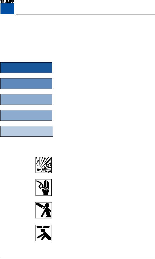
Explosion hazard warns against use of the iLED lighting system in combustible mixtures of anesthetics with air, oxygen or laughing gas.
Electric shock warns of the danger of electric shock, which may result in serious injury or even death.
Sudden release of spring arm warns of the sudden release of the spring arm if the light head is removed without firstly putting the spring arm in the highest possible limit stop position.
Falling lighting system warns of equipment suddenly falling if additional loads are placed on the lighting system.
7200681 Installation Instructions iLED D Lighting System – 07/07 |
13 |

3Your Safety is Important to Us
3.2Symbols used on the iLED Lighting System
CE conformity marking
Device tested by Underwriter Laboratories Inc. for USA and Canada. UL/cUL Classification with respect to electric shock, fire, and mechanical hazards only in accordance with UL 60601-1 and CAN/CSA C22.2 No. 601.1 22TF.
14 |
7200681 Installation Instructions iLED D Lighting System – 07/07 |
3 Your Safety is Important to Us
3.3Overview of the Most Important Safety Information
Please also comply with the safety information in the individual sections.
Installation site
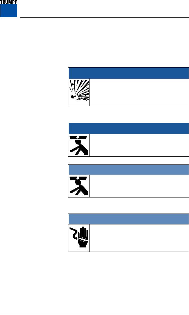
DANGER
Gas explosion
Combustible mixtures of anesthetics with air, oxygen or laughing gas may not be used in environments in which the iLED lighting system is operated.
Danger of the lighting system falling
DANGER
Parts falling from overhead
Make sure that no-one is standing below the lighting system whilst it is being installed.
1WARNING
Danger of the lighting system falling
Comply with the torques for the fixing screws specified in these Installation Instructions.
Hazards from electric shock
1WARNING
Switch off the building power supply
During all installation work the building power supply must be de-energized and prevented from being switched back on again.
7200681 Installation Instructions iLED D Lighting System – 07/07 |
15 |
4 Identification with Serial Numbers
Figure 1 |
4.1 Use of Serial Numbers |
The components of the iLED lighting system are identified with serial numbers:
•The serial numbers define the components of a specified iLED lighting system without any risk of confusion.
• The components of an iLED Lighting System must be installed in the relevant position in accordance with the serial numbers.
4.2 Position of Serial Numbers
• The main serial number can be found on the packaging and also on the top of the uppermost extension arm 1.
• The positions of the serial numbers are shown in “Figure 1”, page 16.
16 |
7200681 Installation Instructions iLED US Lighting System – 07/07 |
|
5 Installing the Ceiling Anchor Plate |
|
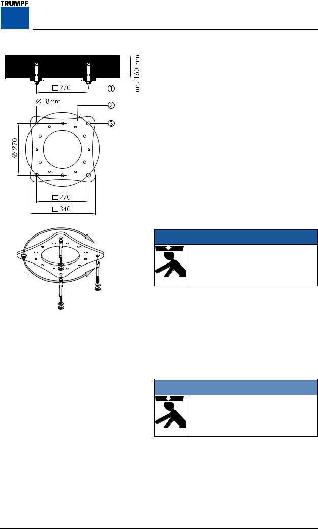
Figure 2 |
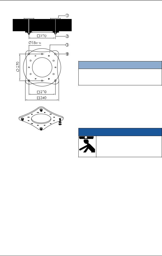
5.1 Installation using Heavy Load Anchors |
|
|
Check the requirements for secure ceiling attachment |
|
|
as specified in “Section 2.1”, page 11. |
|
|
The attachment equipment is described in |
|
|
“Section 2.2”, page 11. |
|
|
1. |
Mark the position of the ceiling anchor plate 2 on |
|
|
the ceiling in accordance with the plan drawing |
|
|
using the drilling template (#4019364). |
|
Drill holes: |
|
|
2. |
Drill four holes 3 in accordance with the |
|
|
instructions from the manufacturer of the fixtures. |
|
• |
Blow out the holes thoroughly. |
|
3. |
Knock a heavy load anchor 1 into the raw ceiling |
|
|
as far as the mark in accordance with the |
|
|
instructions from the manufacturer of the fixtures. |
|
Installing the ceiling anchor plate: |
|
|
|
DANGER |
|
|
Falling ceiling panel |
|
|
Make sure that no-one is standing |
|
|
below the ceiling anchor plate 2 whilst |
|
|
it is being installed. |
4. Loosely screw the ceiling anchor plate 2 to the heavy load anchor 1 that was installed first.
5.Align the ceiling anchor plate 2 with the remaining drill holes 3.
6.Knock the three remaining heavy load anchors 1 into the raw ceiling through the drill holes 3 in the ceiling anchor plate 2 as far as the mark.
Tightening the heavy load anchors:
1WARNING
Danger of the lighting system falling
Tighten the heavy load anchors 1 in accordance with the instructions from the manufacturer of the fixtures.
7.Tighten the heavy load anchors 1 uniformly in accordance with the instructions from the manufacturer of the fixtures.
8.Check that the ceiling anchor plate 2 is securely in place.
•The ceiling anchor plate 2 must lie flush with the raw ceiling.
7200681 Installation Instructions iLED US Lighting System – 07/07 |
17 |
5 Installing the Ceiling Anchor Plate
Figure 3 |
5.2 Installation using Counterplates |
|
Check the requirements for secure ceiling attachment |
|
as specified in “Section 2.1”, page 11. |
|
The fixtures are described in “Section 2.2”, page 11. |
|
1. Mark the position of the ceiling anchor plate 3 in |
|
accordance with the plan drawing using the |
|
drilling template (#4019364). |
|
Drilling holes: |
NOTE
Faulty, misaligned drill holes
Drill the holes 4 from the underside of the raw ceiling.
2. Drill four holes 4, with a 20mm diameter, and always from the underside of the raw ceiling.
3. Push four counterplates with threaded bolts 1 (#4021131) through the drill holes from the top side of the raw ceiling.
Installing the ceiling anchor plate:
DANGER
Falling ceiling anchor plate
Make sure that no-one is standing below the ceiling anchor plate 3 whilst it is being installed.
4. Position the ceiling anchor plate 3 on an M16 threaded bolt 1 and screw on loosely with a washer and M16 hexagon nut 2.
5. Push the three remaining threaded bolts 1 into the ceiling anchor plate 3 and screw each one firmly in place using 1 washer and hexagon nut 2.
Tightening the hexagon nuts:
6. Tighten the hexagon nuts 2 uniformly to 195Nm.
• At the same time, prevent the counterplates 1from turning.
18 |
7200681 Installation Instructions iLED US Lighting System – 07/07 |

|
6 Installing Threaded Bolts or Spacers |
Figure 4 |
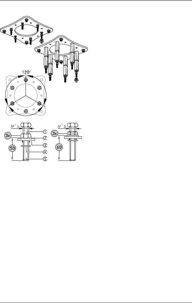
6.1 Installing Threaded Bolts on the |
|
Ceiling Anchor Plate |
|
1. Screw the hexagon nuts 2 onto the threaded bolts |
|
3 (length 110mm) at intervals of min. 25mm. |
1WARNING
Danger of the lighting system falling
Screw threaded bolt 3 into the ceiling anchor plate 1 as far as it will go.
2. Screw six threaded bolts 3 as far as they will go into the ceiling anchor plate 1.
Tightening the hexagon nuts:
3. Tighten the hexagon nuts 2 uniformly to 195Nm.
Figure 5 |
6.2 Installing Optional Spacers on the |
|
Ceiling Anchor Plate |
The length of the six spacers depends on the specific order.
1WARNING
Danger of the lighting system falling
Screw threaded bolt 3 into the ceiling anchor plate 1 as far as it will go.
1. Screw six threaded bolts 5 as far as they will go into the ceiling plate 1.
2. Push the spacers 2 onto the threaded bolts 5 and put a washer 3 and a hexagon nut 4 on each of them.
Tightening the hexagon nuts:
3. Tighten the hexagon nuts 4 to 195Nm.
• Check that the spacers 2 are securely in place.
7200681 Installation Instructions iLED US Lighting System – 07/07 |
19 |
7 Installing the Ceiling Flange
Figure 6 |
7.1 Preparing for Installation |
|
|
Irrespective of the attachment elements specified in |
|
|
“Section 6”, page 19, the following settings always |
|
|
remain the same. |
|
|
1. |
Screw three hexagon nuts 1, offset by 120° and |
|
|
spaced 50mm, onto 3 threaded bolts 5. |
|
• |
Screw the remaining 3 hexagon nuts 1 a little |
|
|
higher e.g. 60 mm. |
Aligning the hexagon nuts horizontally:
2. Horizontally align the three lower hexagon nuts 1 (spaced 50mm) using a spirit level.
Installing upper insulation:
3. Put a washer 2 and plastic insulating disk 3 on the M16 threaded bolt 5 and secure using an O-ring 4.
4.Repeat this procedure for the remaining 5 threaded bolts 5.
7.2 Installing Components on the Ceiling Flange for the Power Supply using Control Box Plates
If no interface plate is installed on the ceiling tube of the ceiling flange, further components must be installed on the ceiling flange depending on the particular iLED lighting system variant.
Install the components on the floor beforehand according to the following sections and then install the ceiling flange as described in “Section 7.3”, page 25.
20 |
7200681 Installation Instructions iLED US Lighting System – 07/07 |
|
|
7 Installing the Ceiling Flange |
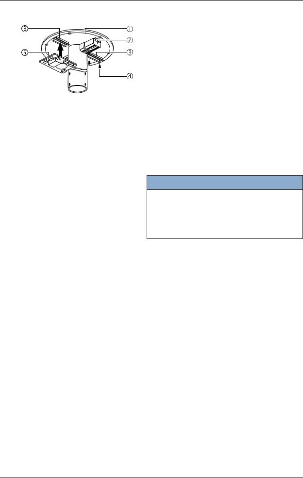
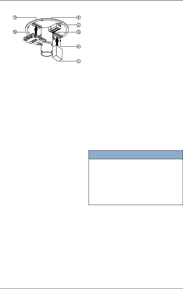
Figure 7 |
7.2.1 Variant: Light head without camera and |
|
|
|
cable lengths of 1 - 20 m |
|
Components to be installed: |
|
|
• |
1 top-hat rail and 1 terminal |
|
1. |
Screw the top-hat rail 2 to the ceiling flange 1 |
|
|
using two M5 x 16mm socket head cap |
|
|
screws 3. |
2.Push the terminal 4 onto the top-hat rail 2 and check that it is securely in place.
Electrical connection for iLED 5 / iLED 5 LCH / iLED 3 light heads:
•Route the cables into the control box plate in the control box and connect according to circuit diagram #4025890.
Electrical connection for iLED 3 LCH light head:
•Route the cables into the control box plate in the control box and connect according to circuit diagram #1431888.
7200681 Installation Instructions iLED US Lighting System – 07/07 |
21 |
7 Installing the Ceiling Flange
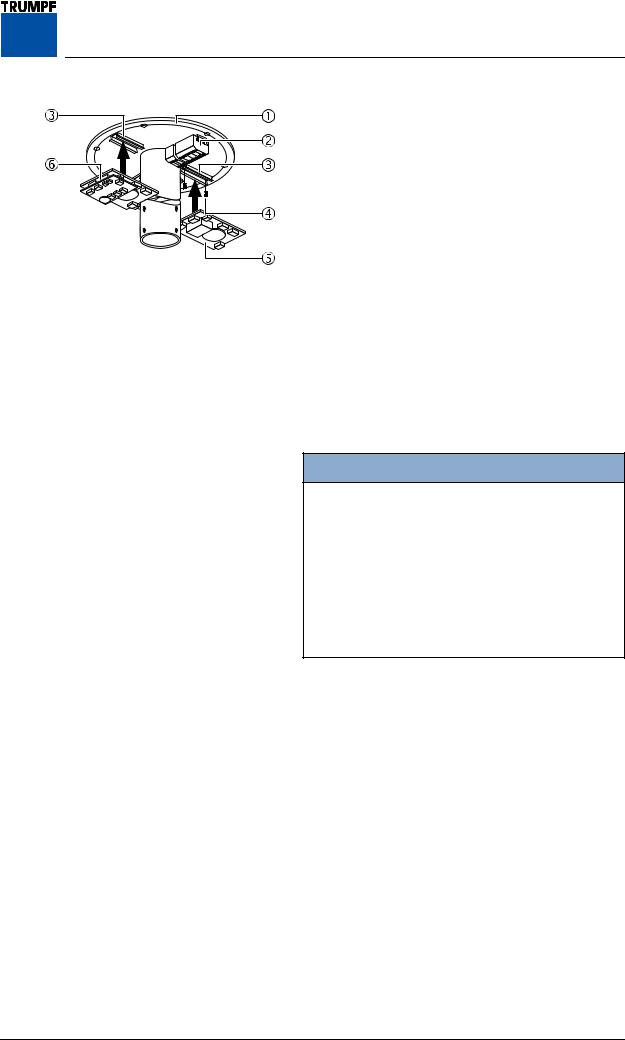
Figure 8 |
7.2.2 Variant: Light head without camera and |
|
|
|
cable lengths of 21 - 50 m |
|
Components to be installed: |
|
|
• |
1 top-hat rail and 1 terminal |
|
• |
1 top-hat rail and 1 filter board per light head |
|
Installing the top-hat rails 3: |
|
|
1. |
For each component, screw one top-hat rail 3 to |
|
|
the ceiling flange 1 using two M5 x 16mm socket |
|
|
head cap screws 4. |
Installing the terminal 2:
2.Install one terminal 2 as described in “Section 7.2.1”, page 21, point 2et seqq.
Installing the filter board(s) 5:
NOTE
Filter boards:
• The filter board 5 (without Powerline additional board) is required to boost the control signals from the light head where the cables are between 21 - 50 m in length.
3.For each light head, fit one filter board 5 on the top-hat rail 3 and check that it is securely in place.
Electrical connection for iLED 5 / iLED 5 LCH / iLED 3 light heads:
•Route the cables into the control box plate in the control box and connect according to circuit diagram #4025743.
Electrical connection for iLED 3 LCH light head:
•Route the cables into the control box plate in the control box and connect according to circuit diagram #1431892.
•Remove the jumpers in A and B on terminal X204.
22 |
7200681 Installation Instructions iLED US Lighting System – 07/07 |
|
7 Installing the Ceiling Flange |
Figure 9 |
7.2.3 Variant: Light head with camera and cable |
|
lengths of 1 - 50 m |
|
Components to be installed: |
|
• 1 top-hat rail and 1 terminal |
|
• 1 top-hat rail and 1 filter board per light head |
|
without camera |
|
• 1 top-hat rail and 1 filter board with Powerline |
|
additional board per light head with camera |
Installing the top-hat rails 3:
1.For each component, screw one top-hat rail 3 to the ceiling flange 1 using two M5 x 16mm socket head cap screws 4.
Installing the terminal 2:
2.Install one terminal 2 as described in “Section 7.2.1”, page 21, point 2et seqq.
Installing the filter board(s) 5:
NOTE
Filter boards:
• The filter board with Powerline additional board 6 is required to boost the video signal from the camera and the control signals from the light head.
• The filter board 5 (without Powerline additional board) is required to boost the control signals from further light heads without camera where the cables are between 21 - 50 m in length.
3.For each light head, fit one filter board 5 on the top-hat rail 3 and check that it is securely in place.
Install filter board with Powerline additional board 6:
4.Fit one filter board with Powerline additional board 6 for the camera connection on the top-hat rail 2 and check that it is securely in place.
Electrical connection for iLED 5 light head:
5.Route the cables into the control box plate in the control box and connect according to the relevant circuit diagram #4025895.
Electrical connection for iLED 3 LCH light head:
6.Route the cables into the control box plate in the control box and connect according to circuit diagram #1442682.
7200681 Installation Instructions iLED US Lighting System – 07/07 |
23 |
7 Installing the Ceiling Flange
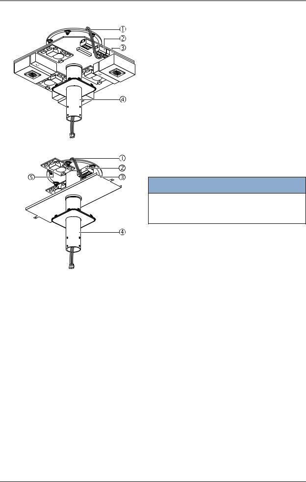
Figure 10 |
7.2.4 Variant with camera on separate pendant |
Components to be installed:
• 1 top-hat rail and 1 terminal
• 1 top-hat rail and 1 power supply unit
• 1 top-hat rail and 1 filter board with Powerline additional board
Installing the top-hat rails 3:
1. For each component, screw one top-hat rail 3 to the ceiling flange 1 using two M5 x 16mm socket head cap screws 4.
Installing the terminal 2:
2.Install one terminal 2 as described in “Section 7.2.1”, page 21, point 2et seqq.
Install power supply unit 5 for 230 V building power supply:
3.Fit the power supply unit 5 for the camera on the top-hat rail 3 and check that it is securely in place.
Installing filter board with Powerline additional board 6:
NOTE
Filter boards:
• The filter board with Powerline additional board 6 is required to boost the video signal from the camera.
• If there are more light heads and cable lengths of 2150m (an)other filter board(s) (without Powerline additional board) must be installed to boost the control signals from the light head.
4.Fit one filter board with Powerline additional board 6 for the camera connection on the top-hat rail 3 and check that it is securely in place.
Electrical connection for 230V:
5.Connect cables for 230 V building power supply according to circuit diagram #1432289.
Electrical connection for 24V:
6.Connect cables for 24 V building power supply according to circuit diagram #1440162.
24 |
7200681 Installation Instructions iLED US Lighting System – 07/07 |

|
7 Installing the Ceiling Flange |
Figure 11 |
7.3 Installing the Ceiling Flange |
|
1. Place the ceiling flange 2 on the 6 threaded bolts |
|
1 and, using three hexagon nuts 7, turn and |
|
move to the position of the non-aligned hexagon |
|
nuts (spaced 60mm). |
|
1WARNING |
|
Danger of the lighting system falling |
|
Screw the hexagon nuts 6 onto the |
|
threaded bolts 1 as far as they will go. |
|
Installing lower insulation: |
|
2. Fit a plastic insulating disk 3, washer 4 and self- |
|
locking hexagon nut 5 on the three aligned |
|
threaded bolts 1. |
|
3. Gently tighten the three hexagon nuts 5. |
Checking horizontal alignment:
4. Check the horizontal alignment of the ceiling flange 2 and tighten the 3 self-locking hexagon nuts 5 to 70Nm.
5.Screw the three upper hexagon nuts 8 downward (spaced 60mm).
6.Remove the three hexagon nuts 7 (that were previously fitted) from the threaded bolts 1, fit them as described in point 2, and tighten to
70Nm.
•Check that the ceiling flange 2 is securely in place.
7200681 Installation Instructions iLED US Lighting System – 07/07 |
25 |

8 Installing an Interface Plate or Canopy Retainer Plate
Figure 12 |
8.1 Installing an Interface Plate |
|
|
If there is no interface plate installed, then the canopy |
|
|
retainer plate must be installed as described in |
|
|
“Section 8.2”, page 27. |
|
|
Preparing to install the split rings 5/6: |
|
|
1. |
Prepare two split rings 5/6 by screwing 2 socket |
|
|
head cap screws and M8 x 40mm retaining |
|
|
washers 5. |
|
Adjusting the height of the interface plate: |
|
|
2. |
Slide the split ring 6 onto the ceiling tube 1. |
|
3. |
Adjust the height on the lower edge of the split ring |
|
|
6 on the ceiling tube 1: |
•With canopy:
-Canopy 300 = 136 mm
-Canopy 200 = 36 mm
- Canopy 100 = 147 mm
• With ceiling screen:
- Ceiling screen = 167 mm
4. Tighten the M8 x 40mm socket head cap screws 4 on the split ring 6.
Installing the interface plate:
5. Slide the interface plate 2 and the second split ring 5 onto the ceiling tube 1 and align in accordance with the ceiling recess.
6. Tighten the M8 x 40mm socket head cap screws 4 on the split ring 5.
7. Check that the interface plate 2 is securely in place.
Installing the canopy cover 3:
8. Slide the canopy cover 3 onto the ceiling tube 1. 9. Prevent the canopy cover 3 from falling down
until the canopy or ceiling screen is installed.
26 |
7200681 Installation Instructions iLED US Lighting System – 07/07 |

8 Installing an Interface Plate or Canopy Retainer Plate
Figure 13 |
8.2 Installing a Canopy Retainer Plate |
|
|
In order to later install the canopy and/or a ceiling |
|
|
screen, the canopy retainer plate must be installed. |
|
|
Preparing to install the split rings 5/6: |
|
|
1. |
Prepare two split rings 5/6 by screwing 2 socket |
|
|
head cap screws and M8 x 40mm retaining |
|
|
washers 5 into each. |
|
Adjusting the height of the canopy retainer plate: |
|
|
2. |
Slide the split ring 6 onto the ceiling tube 1. |
|
3. |
Adjust the height on the lower edge of the split ring |
|
|
6 on the ceiling tube 1: |
|
• |
With canopy: |
|
|
- Canopy 200 = 116 mm |
|
• |
With ceiling screen: |
|
|
- Ceiling screen = 102 mm |
|
4. |
Tighten the M8 x 40mm socket head cap screws |
|
|
4 on the split ring 6. |
Installing the canopy retainer plate:
5.Slide the canopy retainer plate 2 and second split ring 5 onto the ceiling tube 1 and align in
accordance with the ceiling recess.
6. Tighten the M8 x 40mm socket head cap screws 4 on the split ring 5.
7.Check that the canopy retainer plate 2 is securely in place.
Installing the canopy cover 3:
8.Slide the canopy cover 3 onto the ceiling tube 1.
9.Prevent the canopy cover 3 from falling down until the canopy or ceiling screen is installed.
7200681 Installation Instructions iLED US Lighting System – 07/07 |
27 |
9 Installing the Central Axis with Extension Arm
Figure 14 |
9.1 Routing Five-pole Cables for Light |
|
Heads without Camera through the |
|
Ceiling Tube |
The separate 5-pole cables for light heads without camera must first be routed through the ceiling tube to the terminal on the interface plate or the ceiling flange.
The 5-pole cables must be labeled to enable the light heads without camera to be connected without any risk of confusion.
Labeling five-pole cables:
1. Label the five-pole cables 1 with numbers on the ends of the cable (depending on the number of light heads without camera).
Routing five-pole cables through the ceiling tube:
NOTICE
Take care not to damage the cables
Carefully, without using a great deal of force, route the cables 1 through the central tube 4.
2. Route the five-pole cables 1 through the ceiling tube 4 to terminal (X201) 2 on the interface plate or route them directly to the filter board (X9) 5 on the ceiling flange 3.
Connecting the five-pole cables to the interface plate:
• Connect the five-pole cables 1in accordance with the circuit diagrams:
-230/24 V supply voltage #1431878,
-24/24 V supply voltage) #1431885,
-24 V supply voltage #1431887,
-230 V supply voltage #1431882,
-230/230V supply voltage #1431884,
and your cable labeling to terminal Klemme 2 on the interface plate.
Connecting five-pole cables to the ceiling flange:
1. Connect the five-pole cables 1 in accordance with the circuit diagrams:
-connection lengths 1 - 20m #4025890,
-connection lengths 21 - 50 m #4025743, and your cable labeling to terminal 2 on the ceiling flange 3.
28 |
7200681 Installation Instructions iLED US Lighting System – 07/07 |

|
9 Installing the Central Axis with Extension Arm |
Figure 15 |
9.2 Routing Seven-pole Cables for Light |
|
Heads with Camera through the |
|
Ceiling Tube |
The 7-pole cables from the central axis must be routed through the ceiling tube to the interface plate or the ceiling flange.
The 7-pole cables from the central axis must be labeled to enable the light heads with camera to be connected without any risk of confusion.
Labeling seven-pole cables:
1. Label the seven-pole cables 1 with numbers on the ends of the cable (depending on the number of light heads without camera).
Routing seven-pole cables through the ceiling tube:
NOTICE
Take care not to damage the cables
Carefully, without using a great deal of force, route the cables 1 through the central tube 3.
2. Route the seven-pole cables 1 through the ceiling tube 3 to the interface plate or the ceiling flange 3.
9.3 Installing the Central Axis
NOTICE
Make sure that the central axis is not tilted.
• It should be possible to install the central axis 6 without using a great deal of force.
• Take care not to damage the cables.
1. Using the lifting device, raise the central axis 6. 2. Connect 5-pole cable plugs 5 (see “Section 9.1”,
page 28).
3. Insert the central axis 6 into the ceiling tube 3 and screw it in place using 8 M6 x 10mm countersunk head screws 4.
4. Tighten the eight M6 x 10mm countersunk head screws 4 to 10Nm.
5.Check that the central axis 6 is securely in place.
6.Fit the eight M6 x 10mm countersunk head screws 4 with plastic caps.
7200681 Installation Instructions iLED US Lighting System – 07/07 |
29 |

10 Connecting the Cables
Figure 16 |
10.1 Connection Variants for Light Heads |
|
without Camera |
|
10.1.1 Connection to the interface plate |
1. Connect the connecting cable plugs 1 in accordance with your cable labeling in “Section 9.1”, page 28 and the circuit diagrams:
- 230/24 V supply voltage #1431878, - 24/24 V supply voltage #1431885,
-230 V supply voltage #1431882,
-230/230 V supply voltage #1431884,
-iLED 3 LCH for all supply voltages #1431896 to terminal 2.
2.Connect the connecting cables (to be laid by customer) to the terminals 2.
Figure 17 |
10.1.2 Connection via interface plate(s) where |
|
|
|
cables are between 1 - 20m in length |
|
1. |
Disconnect the connecting cable plugs 1. |
|
2. |
Connect the connecting cables 1 in accordance |
|
|
with your cable labeling in “Section 9.1”, page 28 |
|
|
and the |
-circuit diagram #4025890,
-for iLED 3 LCH in accordance with circuit diagram #1431888 to the terminals 2 on the ceiling
flange.
3.Connect the ground conductor to the terminal 2.
4.Connect the connecting cables (to be laid by customer) from the control box plate(s) to the terminals 2.
30 |
7200681 Installation Instructions iLED US Lighting System – 07/07 |
 Loading...