

Page 1
iLED Lighting System
Installation Instructions
Page 2

To the Service Technician
Conformity The manufacturer declares that this product conforms to the
Please read through these Installation Instructions with great care
and comply with the safety information and requirements for
installation.
CE marking
This item of equipment is a Class I medical device as defined by the
European Medical Device Directive (MDD) 93/42/EEC, June 1993,
Appendix IX.
fundamental requirements according to MDD Appendix I and
documents this by means of the CE marking.
What equipment forms the subject of these Installation
Instructions?
iLED Lighting System:
• single luminaire version:
with one iLED 3 or iLED 5 light head,
• surgical lighting system version:
with a combination of 2 to 3
iLED 3 or iLED 5 light heads,
• plus optional extra equipment.
Customer Service is at your disposal
• if you have any questions on the equipment or its installation,
• if you would like to re-order spare parts,
• for servicing or warranty claims.
How to reach us
• TRUMPF KREUZER Medizin Systeme GmbH + Co. KG
Benzstrasse 26
82178 Puchheim, Germany
Sales • Telephone: ++49 / (0)89 / 8 09 07 - 0
• Fax: ++49 / (0)89 / 8 09 07 - 2 22
Service • Telephone: 0 180 / 2 25 41 35
Telephone: ++49 / (0)36 71/ 5 86 - 0
• Fax: ++49 / (0)36 71 / 58 61 75
© TRUMPF KREUZER, 2007
• Edition: 07/2007, Version 2 (Index 01)
As on: 07.03.2007
Visit us on the Internet www.Trumpf-med.com
2
7200681 Installation Instructions iLED Lighting System US – 07/07
Page 3

Notes relating to this documentation
Applicability • These Installation Instructions are only valid in conjunction with
the iLED planning specification.
Copyright • The information contained in these Installation Instructions and
parts thereof are the intellectual property of TRUMPF KREUZER
Medizin Systeme GmbH + Co. KG, hereinafter TRUMPF, and is
protected by national and international copyright and other laws
for the protection of intellectual property.
• Any duplication, reproduction, translation, microfilming, storage
– in either electronic or magnetic form – , processing as
electronically or magnetically stored data, copying or distribution
of these documents and/or the information contained herein or
parts thereof without the prior written approval of TRUMPF is
hereby strictly prohibited.
We reserve the right to make changes • TRUMPF shall assume no liability whatsoever on the basis of, or
in association with, the use of said information prohibited in this
manner by any person or company.
TRUMPF reserves the right to amend, delete or modify in any
other manner all information contained herein at any time and
on any grounds without prior notice.
We are constantly engaged in the further development of our
products and reserve the right to make changes to the scope
of supply in terms of design, equipment or technology.
Copyrights • TRUMPF expressly reserves all rights in accordance with
copyright law.
Protection laws • All printed material corresponds to the version of the iLED lighting
system and to the status of the safety standards that it is based on
at the time of printing. All protection rights are reserved for
devices, circuits, processes, software programs and names
specified therein.
Translations • The German-language version of these Installation Instructions
shall be binding as regards translations into foreign languages.
Trademarks • All trademarks mentioned in these Installation Instructions are the
exclusive property of the respective suppliers and/or
manufacturers.
7200681 Installation Instructions iLED Lighting System US – 07/07
3
Page 4

Contents
1 Important Information ....................................................................................................7
1.1 Delivery .......................................................................................................................7
1.2 Identification of Components with Serial Numbers ..........................................................7
1.3 Equipment Required for Installation................................................................................8
1.4 Service Technician Qualification Requirements ...............................................................8
1.5 Installation Site Requirements ........................................................................................9
1.6 Intended Use................................................................................................................9
1.7 Warranty and Liability .................................................................................................10
2 Customer Requirements ...............................................................................................11
2.1 Secure Attachment to Ceiling ......................................................................................11
2.2 Ceiling Attachment Equipment Specifications................................................................11
2.3 Customer's Electrical Installation ..................................................................................12
3 Your Safety is Important to Us .......................................................................................13
3.1 Symbols used in these Installation Instructions...............................................................13
3.2 Symbols used on the iLED Lighting System....................................................................14
3.3 Overview of the Most Important Safety Information .......................................................15
4 Identification with Serial Numbers ................................................................................16
4.1 Use of Serial Numbers................................................................................................16
4.2 Position of Serial Numbers ..........................................................................................16
5 Installing the Ceiling Anchor Plate ................................................................................17
5.1 Installation using Heavy Load Anchors .........................................................................17
5.2 Installation using Counterplates...................................................................................18
6 Installing Threaded Bolts or Spacers ..............................................................................19
6.1 Installing Threaded Bolts on the Ceiling Anchor Plate....................................................19
6.2 Installing Optional Spacers on the Ceiling Anchor Plate ................................................19
7 Installing the Ceiling Flange .........................................................................................20
7.1 Preparing for Installation .............................................................................................20
7.2 Installing Components on the Ceiling Flange for the Power Supply
using Control Box Plates .............................................................................................20
7.3 Installing the Ceiling Flange ........................................................................................25
8 Installing an Interface Plate or Canopy Retainer Plate ...................................................26
8.1 Installing an Interface Plate..........................................................................................26
8.2 Installing a Canopy Retainer Plate................................................................................27
9 Installing the Central Axis with Extension Arm ...............................................................28
9.1 Routing Five-pole Cables for Light Heads without Camera through the Ceiling Tube.......28
9.2 Routing Seven-pole Cables for Light Heads with Camera through the Ceiling Tube.........29
9.3 Installing the Central Axis ............................................................................................29
4
7200681 Installation Instructions iLED Lighting System US – 07/07
Page 5

Contents
10 Connecting the Cables .................................................................................................30
10.1 Connection Variants for Light Heads without Camera ...................................................30
10.2 Connection Variants for Light Heads with Camera ........................................................32
10.3 Connection Variant for Camera on Separate Pendant...................................................33
11 Installing a Spring Arm ................................................................................................. 34
11.1 Spring Arm Versions ...................................................................................................34
11.2 Preparing for Installation for all Spring Arm Variants......................................................35
11.3 Installing Spring Arm for Light Head without Camera ....................................................36
11.4 Installing Spring Arm for Light Head with Camera.........................................................37
11.5 Installing Spring Arm for vidiaPORT Monitor Installations...............................................38
11.6 Adjusting Arm Stop on the Acrobat Space Spring Arm ..................................................38
11.7 Installing the Cover.....................................................................................................39
12 Installing the Horizontal Bar on the iLED 5 Light Head .................................................. 40
12.1 Installing the Horizontal Bar on the iLED 5 Light Head without Camera ..........................40
12.2 Installing the Horizontal Bar on the iLED 5 Light Head with Camera...............................40
13 Installing the Light Head .............................................................................................. 41
13.1 Installing the Light Head without Camera on the Acrobat 2000/3000 Spring Arm ..........41
13.2 Installing the iLED 3 Light Head without Camera on the Acrobat 2000 LCH Spring Arm..42
13.3 Installing the iLED 5 Light Head without Camera on the Acrobat 3000 LCH Spring Arm..43
13.4 Installing the Light Head with Camera on the Acrobat 2000/3000 Spring Arm...............44
13.5 Installing the Light Head iLED 3 with Camera on the Acrobat 2000 LCH Spring Arm ......45
13.6 Installing the Light Head iLED 5 with Camera on the Acrobat 3000 LCH Spring Arm ......46
14 Installing Camera on Separate Pendant ....................................................................... 47
14.1 Installing Camera on Separate Pendant on the Acrobat 2000 Spring Arm......................47
15 Connecting/Disconnecting Counterweight .................................................................... 48
15.1 Connecting the Counterweight ....................................................................................48
15.2 Disconnecting the Counterweight ................................................................................49
16 Installing the vidiaPORT Monitor Attachments ............................................................... 50
16.1 Special Features .........................................................................................................50
16.2 vidiaPORT Versions ....................................................................................................50
16.3 Routing Cables through the vidiaPORT Monitor Adapter ...............................................51
16.4 Routing Cables through the VESA 100 Adapter ............................................................53
16.5 Installing the vidiaPORT Monitor Adapter on the Acrobat 2000/3000 Spring Arm ..........53
16.6 Installing the vidiaPORT Duo Monitor Attachment on the Acrobat Space Spring Arm.......55
16.7 Grounding the Acrobat Space Spring Arm ...................................................................57
16.8 Feeding in Cables ......................................................................................................58
16.9 Installing the Rotating Canopy.....................................................................................59
16.10 Installing the Ceiling Tube Cover.................................................................................60
16.11 Installing the Flat-Screen Monitor.................................................................................61
7200681 Installation Instructions iLED Lighting System US – 07/07
5
Page 6

Contents
17 Installing the Wall-Mounted Control Panel ....................................................................62
17.1 Installing the Flush-Mounted Version of the Wall-Mounted Control Panel .......................62
17.2 Installing the Surface-Mounted Version of the Wall-Mounted Control Panel....................65
18 Adjustments ..................................................................................................................68
18.1 Adjusting Spring Force on the Acrobat 2000/3000 and
Acrobat 2000/3000 LCH Spring Arms.........................................................................68
18.2 Adjusting Spring Force on the Acrobat Space Spring Arm..............................................68
18.3 Adjusting Height Stop on the Acrobat 2000/3000 Spring Arms .....................................69
18.4 Adjusting Height Stop on the Acrobat Space Spring Arm ...............................................69
18.5 Adjusting Height Stop on the Acrobat 2000 LCH Spring Arm.........................................70
18.6 Adjusting Height Stop on the Acrobat 3000 LCH Spring Arm.........................................70
18.7 Adjusting Brake Force on the Acrobat 3000 Spring Arm................................................71
18.8 Adjusting Brake Force on the Acrobat 2000 LCH Spring Arm ........................................71
18.9 Adjusting Brake Force on the Acrobat 3000 LCH Spring Arm ........................................72
18.10 Adjusting Brake Force on the vidiaPORT Monitor Adapter .............................................73
18.11 Adjusting Brake Force on the VESA 100 Adapter ..........................................................73
18.12 Adjusting Brake Force on the Camera Adapter of the Separate Camera.........................74
18.13 Adjusting Brake Force on the iLED Lighting System........................................................75
19 Installing the Canopy ....................................................................................................76
19.1 Installing Brackets on the Interface Plate.......................................................................76
19.2 Installing Brackets on the Canopy Retainer Plate ...........................................................77
19.3 Installing the Canopy..................................................................................................78
20 Functional Check and Customer Instruction ..................................................................79
21 Technical Data ..............................................................................................................80
22 Circuit Diagrams ..........................................................................................................84
22.1 Interface Plate Circuit Diagram (Maximum Equipment)..................................................84
22.2 Circuit Diagram – Control Box Plates...........................................................................89
22.3 Circuit Diagram Distance 1-20m (Maximum Equipment)...............................................94
22.4 Circuit Diagram Distance 21-50m (Maximum Equipment).............................................95
22.5 Circuit Diagram – iLED 3 LCH.....................................................................................96
22.6 Circuit Diagram – Camera on Separate Pendant........................................................100
22.7 Circuit Diagram – System with Camera......................................................................102
22.8 Circuit Diagram – vidiaPORT ....................................................................................104
22.9 Circuit Diagram – Wall-Mounted Control Panel .........................................................105
6
7200681 Installation Instructions iLED Lighting System US – 07/07
Page 7

1 Important Information
1.1 Delivery
Damage during transport • Before installation, check the consignment for any damage that
may have occurred during transport.
- In the event of any damage please contact TRUMPF.
Damage claims - Damage claims can only be considered if TRUMPF is notified
immediately.
Damage report - Please complete a damage report as soon as possible and send
it in to TRUMPF to enable damage claims to be validated.
Returns - If you need to return an item or items, please use the original
packaging if possible.
Accompanying documents • To enable us to deal with the matter speedily, please provide the
following details:
- Name and address of customer,
- Consignee,
- Primary serial number of the iLED lighting system or of the
component concerned (see “Section 4.2”, page 16),
- Description of fault (form: Service Advice Form).
1.2 Identification of Components with Serial
Numbers
• The components of the iLED lighting system are identified with
serial numbers:
- The serial numbers define the components of a specified iLED
lighting system without any risk of confusion.
- The components of an iLED Lighting System must be installed in
the relevant position in accordance with the serial numbers.
• An overview of the identification of a iLED lighting system with
serial numbers can be found in “Section 4”, page 16.
7200681 Installation Instructions iLED D Lighting System – 07/07
7
Page 8

1 Important Information
1.3 Equipment Required for Installation
• Vermette 512 lifting equipment or forklift with a load rating of at
least 250kg.
The lift must correspond at least to the height of the
intermediate ceiling.
• Standard drill equipment or
- Core drill HILTI DD-EC 1,
- with appropriate drill,
- and drilling template (# 4019364).
• Spirit level.
• Torque wrench,
• Calibrated luxmeter,
• Multimeter,
• Standard toolkit,
• Two ladders of the necessary length.
1.4 Service Technician Qualification Requirements
Only for trained service technicians • These Installation Instructions are written for trained service
technicians.
Carrying out installation • The iLED lighting system may only be installed by TRUMPF
Technical Service or by authorized service personnel who have
been trained by TRUMPF.
• When installing the equipment, you must follow the steps given in
these installation instruction in the correct order.
• In the event of damage to the iLED lighting system, installation
must cease.
In the event of problems • If you encounter problems which are not covered by these
Installation Instructions or not covered in sufficient detail, you
should immediately contact your nearest TRUMPF Customer
Service Center for the safety of operators and patients.
8
7200681 Installation Instructions iLED D Lighting System – 07/07
Page 9

1 Important Information
1.5 Installation Site Requirements
• The installation site must satisfy the requirements stated in the
iLED planning specification.
• The iLED lighting system, as a surgical lighting system, must only
be installed in rooms that are used for medical purposes and are
set up in accordance with DIN VDE 0100 - 710 or
IEC 60364-710.
• The ambient temperature during operation must be between
10°C and 40°C.
• The relative humidity must be between 30% and 75%.
• The air pressure must be between 700 and 1060 hPa.
1.6 Intended Use
Proper use • The iLED lighting system is for illuminating an examination and
surgical site on the patient in a hospital or doctor's surgery.
Operating range • It operates at a distance of between 70 cm and 150 cm from the
intervention site.
Single luminaire:
Definition: Small surgical luminaire • One iLED 3 / iLED 5 single luminaire is classified as a small
surgical luminaire under IEC 60601-2-41, and may only be
used for operations where light failure will not put the patient at
risk.
Surgical lighting system:
• A surgical lighting system with multiple light heads can be used
without restriction.
Improper use • The iLED lighting system is not suitable for operation in potentially
explosive atmospheres.
• The iLED lighting system must not be used in environments in
which combustible mixtures of anesthetics with air, oxygen or
laughing gas are used.
• To avoid the possibility of the light heads overheating, never
cover them whilst the lighting system is in operation.
• To avoid any risk of dazzling, never look directly at the light
coming from the light heads.
• It is not permitted to place additional loads on the lamp
suspension.
• Do not expose the iLED lighting system to extreme vibrations.
7200681 Installation Instructions iLED D Lighting System – 07/07
9
Page 10

1 Important Information
1.7 Warranty and Liability
TRUMPF guarantees the safety and functionality of the iLED lighting
system only on condition that:
• installation, modifications and repairs are carried out by TRUMPF
service technicians or other persons expressly authorized by
TRUMPF,
• requirements for secure ceiling attachment have been met,
• the electrical installation of the iLED lighting system complies with
the currently applicable regulations,
• only original components from TRUMPF have been used,
• only approved accessories or those that have been tested for
suitability are installed,
• the iLED lighting system is being used for its intended purpose, in
the proper manner,
• it is commissioned and the equipment is released for operation
with a delivery note.
10
7200681 Installation Instructions iLED D Lighting System – 07/07
Page 11

2.1 Secure Attachment to Ceiling
Acceptance certificate of structural
engineer
Holes drilled incorrectly • In the event that a hole is drilled incorrectly, coming up against a
Ceiling anchor plate • To make sure that the load is distributed correctly, the ceiling
Building regulations must be
observed.
2 Customer Requirements
• It must be ensured during planning that all circumstances
involved in the specific case have been given proper
consideration, the specific approval from the competent building
authorities has been obtained and all installation work has been
performed in the proper manner using suitable tools.
• The structural design of the ceiling must ensure that the loads
imposed by the iLED lighting system and other existing ceiling
loads are absorbed and transferred safely.
• The load-bearing capacity must be calculated and checked by a
structural engineer and confirmed by means of proof
calculations. This structural proof for the load-bearing capacity
of the ceiling must be drawn up and submitted prior to
installation of the iLED Lighting System.
reinforcement rod for instance, the responsible structural
engineer should be consulted to make sure that the load is still
adequately distributed over the ceiling area.
anchor plate
• The national and regional building regulations currently
applicable must be observed.
must be installed flush with the ceiling.
2.2 Ceiling Attachment Equipment Specifications
Reinforced concrete ceilings
Class C20/25
Observe instructions from the
manufacturer of the attachment
equipment
Counterplate set For all other ceilings we recommend the use of a counterplate set for
With properly constructed Class C20/25 (or better) reinforced
concrete ceilings, the following attachment equipment (not included
in scope of supply) should be used (see “Section 5.1”, page 17):
• 4 through-wall anchors,
• HILTI make,
• approval no. ETA-98/0001,
• model HST M16/25,
• minimum thickness of raw ceiling 160 mm.
In order to secure the iLED lighting system correctly to the ceiling you
must observe the instructions from the manufacturer of the
attachment equipment.
ceiling attachment (see “Section 5.2”, page 18):
• 4 counterplates with threaded rods M16 (# 4021131),
• 4 M16 hexagon nuts – DIN 934 (# 5200031),
• 4 washers 19.00 – DIN 125 (# 5301901).
7200681 Installation Instructions iLED D Lighting System – 07/07
11
Page 12

2 Customer Requirements
2.3 Customer's Electrical Installation
Installation by specialist external
contractors
Work must be carried out by qualified
electricians
National regulations must be
observed
Device for disconnecting all poles from
the power supply
The electrical connections on the customer's premises must be
implemented by a specialist company commissioned by the
customer as per the iLED planning specification. The following
requirements must be observed:
• Planning, execution and checking of the electrical installation
must be carried out at the customer's premises by competent
electrical engineers and licenced electrical contractors.
• If the applicable regulations in the country concerned require the
device to be connected to the power supply by authorized
specialist engineers, it is important to ensure that they are
observed.
• A device must be installed on the customer's premises which
disconnects all poles of the power supply cables from the power
supply network.
• The terminal blocks must be freely accessible for installation of
the iLED lighting system and performance of the required
electrical safety checks.
• The electrical installations of the room concerned must comply
with the applicable national regulations. DIN VDE 0100 part
710 is applicable in the Federal Republic of Germany.
The requirements of NFPA 70 and NFPA 99 are applicable in
the USA.
12
7200681 Installation Instructions iLED D Lighting System – 07/07
Page 13
3 Your Safety is Important to Us
3.1 Symbols used in these Installation Instructions
Important information is shown in these Installation Instructions
using symbols and signal words.
Signal words such as DANGER, WARNING or CAUTION indicate the
level of risk. This is visually emphasized by the different triangle
symbols.
DANGER
1WARNING
1CAUTION
NOTICE
NOTE
DANGER alerts you to an immediate dangerous situation, which –
unless avoided – will result in death or serious injury.
WARNING alerts you to a potentially dangerous situation, which –
unless avoided – may result in death or serious injury.
CAUTION alerts you to a potentially dangerous situation, which –
unless avoided – may result in minor or slight injury.
NOTICE indicates a potentially dangerous situation, which – unless
avoided – will lead to damage to property.
NOTE gives you additional information and helpful tips for the safe
and efficient use of the appliance.
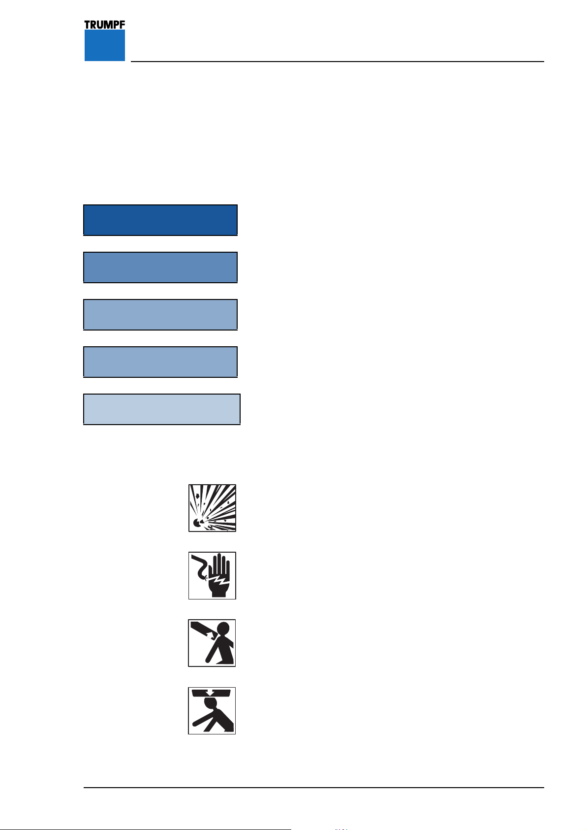
The following symbols and signal words define the potential threat
more precisely.
Explosion hazard
combustible mixtures of anesthetics with air, oxygen or laughing gas.
warns against use of the iLED lighting system in
Electric shock warns of the danger of electric shock, which
may result in serious injury or even death.
Sudden release of spring arm warns of the sudden release of the
spring arm if the light head is removed without firstly putting the
spring arm in the highest possible limit stop position.
Falling lighting system warns of equipment suddenly falling if
additional loads are placed on the lighting system.
7200681 Installation Instructions iLED D Lighting System – 07/07
13
Page 14

3 Your Safety is Important to Us
3.2 Symbols used on the iLED Lighting System
CE conformity marking
Device tested by Underwriter Laboratories Inc. for USA and Canada.
UL/cUL Classification with respect to electric shock, fire, and
mechanical hazards only in accordance with UL 60601-1 and
CAN/CSA C22.2 No. 601.1 22TF.
14
7200681 Installation Instructions iLED D Lighting System – 07/07
Page 15
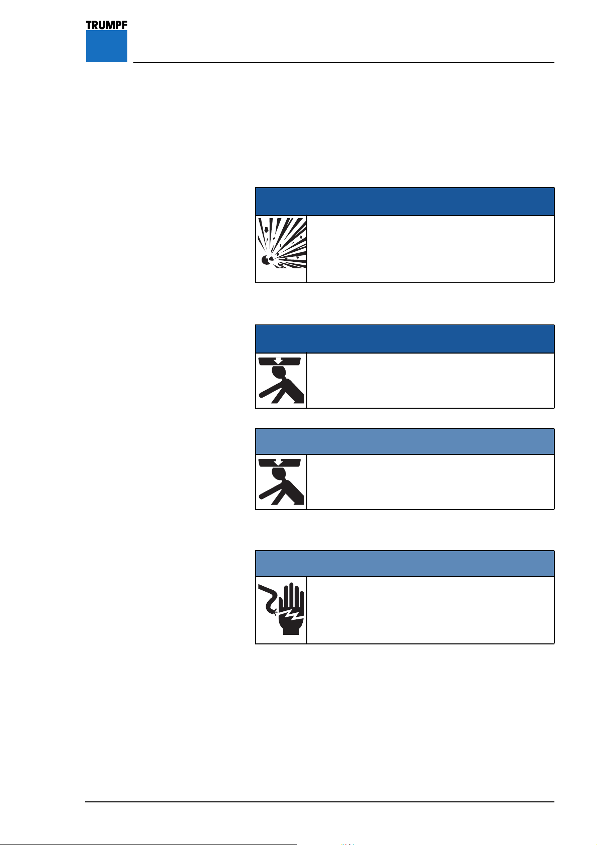
3 Your Safety is Important to Us
3.3 Overview of the Most Important Safety
Information
Please also comply with the safety information in the individual
sections.
Installation site
DANGER
Gas explosion
Combustible mixtures of anesthetics with air, oxygen
or laughing gas may not be used in environments in
which the iLED lighting system is operated.
Danger of the lighting system falling
DANGER
Parts falling from overhead
Make sure that no-one is standing below the
lighting system whilst it is being installed.
1WARNING
Danger of the lighting system falling
Comply with the torques for the fixing screws
specified in these Installation Instructions.
Hazards from electric shock
1WARNING
Switch off the building power supply
During all installation work the building power
supply must be de-energized and prevented from
being switched back on again.
7200681 Installation Instructions iLED D Lighting System – 07/07
15
Page 16
4 Identification with Serial Numbers
Figure 1 4.1 Use of Serial Numbers
The components of the iLED lighting system are
identified with serial numbers:
• The serial numbers define the components of a
specified iLED lighting system without any risk of
confusion.
• The components of an iLED Lighting System must
be installed in the relevant position in accordance
with the serial numbers.
4.2 Position of Serial Numbers
• The main serial number can be found on the
packaging and also on the top of the uppermost
extension arm 1.
• The positions of the serial numbers are shown in
“Figure 1”, page 16.
16
7200681 Installation Instructions iLED US Lighting System – 07/07
Page 17
5 Installing the Ceiling Anchor Plate
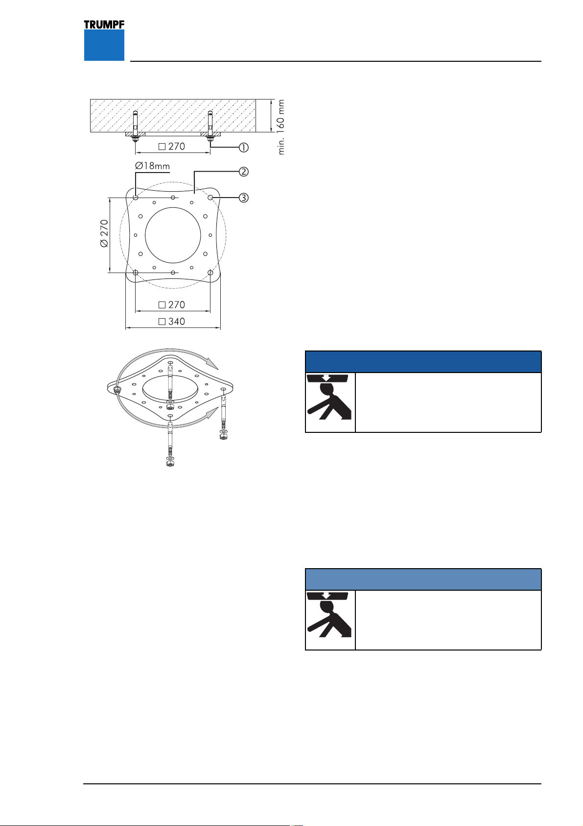
Figure 2 5.1 Installation using Heavy Load Anchors
Check the requirements for secure ceiling attachment
as specified in “Section 2.1”, page 11.
The attachment equipment is described in
“Section 2.2”, page 11.
1. Mark the position of the ceiling anchor plate 2 on
the ceiling in accordance with the plan drawing
using the drilling template (#4019364).
Drill holes:
2. Drill four holes 3 in accordance with the
instructions from the manufacturer of the fixtures.
• Blow out the holes thoroughly.
3. Knock a heavy load anchor 1 into the raw ceiling
as far as the mark in accordance with the
instructions from the manufacturer of the fixtures.
Installing the ceiling anchor plate:
DANGER
Falling ceiling panel
Make sure that no-one is standing
below the ceiling anchor plate 2 whilst
it is being installed.
4. Loosely screw the ceiling anchor plate 2 to the
heavy load anchor 1 that was installed first.
5. Align the ceiling anchor plate 2 with the
remaining drill holes 3.
6. Knock the three remaining heavy load anchors 1
into the raw ceiling through the drill holes 3 in the
ceiling anchor plate 2 as far as the mark.
Tightening the heavy load anchors:
1WARNING
Danger of the lighting system falling
Tighten the heavy load anchors 1 in
accordance with the instructions from
the manufacturer of the fixtures.
7200681 Installation Instructions iLED US Lighting System – 07/07
7. Tighten the heavy load anchors 1 uniformly in
accordance with the instructions from the
manufacturer of the fixtures.
8. Check that the ceiling anchor plate 2 is securely
in place.
• The ceiling anchor plate 2 must lie flush with the
raw ceiling.
17
Page 18
5 Installing the Ceiling Anchor Plate
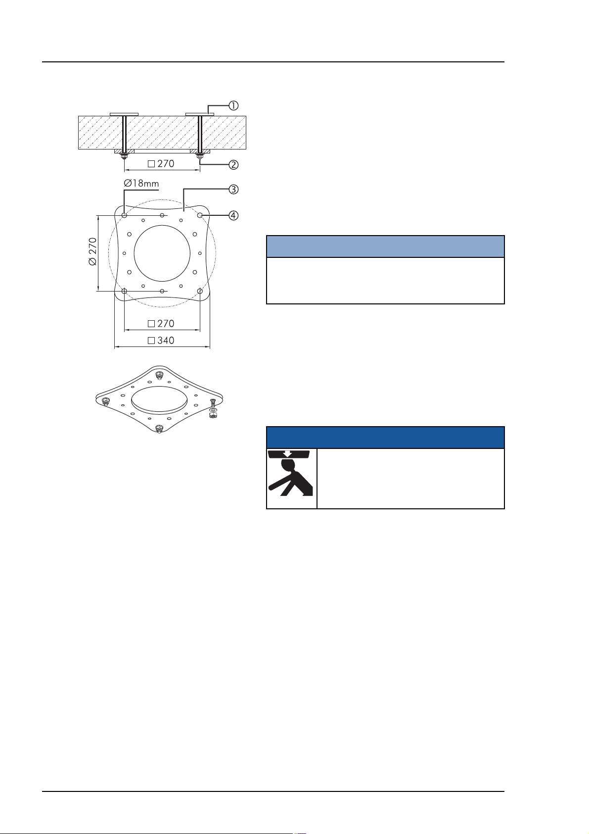
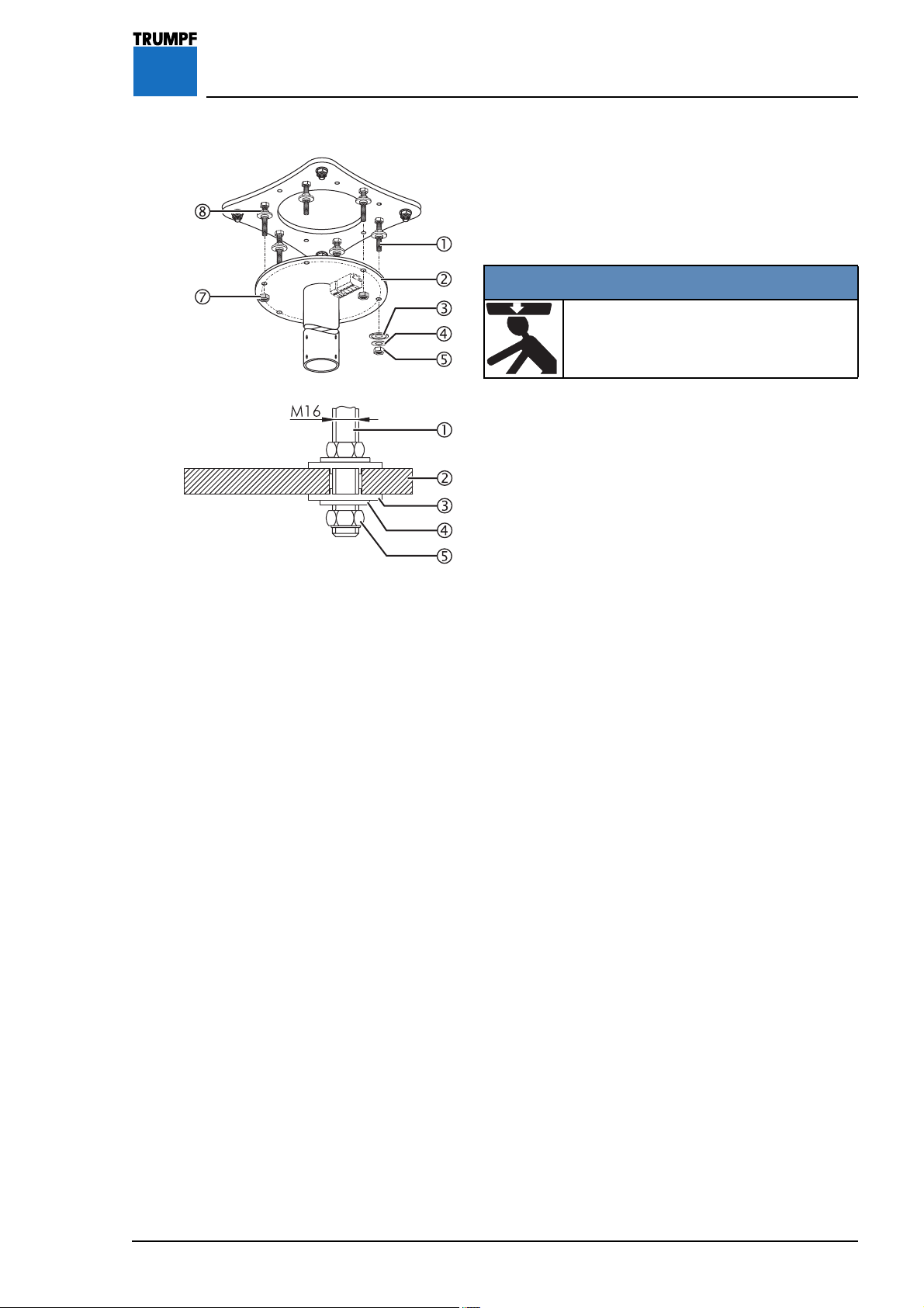
Figure 3 5.2 Installation using Counterplates
Check the requirements for secure ceiling attachment
as specified in “Section 2.1”, page 11.
The fixtures are described in
“Section 2.2”, page 11.
1. Mark the position of the ceiling anchor plate 3 in
accordance with the plan drawing using the
drilling template (#4019364).
Drilling holes:
NOTE
Faulty, misaligned drill holes
Drill the holes 4 from the
ceiling.
underside of the raw
2. Drill four holes 4, with a 20mm diameter, and
always from the underside of the raw ceiling.
3. Push four counterplates with threaded bolts 1
(#4021131) through the drill holes from the top
side of the raw ceiling.
Installing the ceiling anchor plate:
DANGER
Falling ceiling anchor plate
Make sure that no-one is standing
below the ceiling anchor plate 3 whilst
it is being installed.
4. Position the ceiling anchor plate 3 on an M16
threaded bolt 1 and screw on loosely with a
washer and M16 hexagon nut 2.
5. Push the three remaining threaded bolts 1 into
the ceiling anchor plate 3 and screw each one
firmly in place using 1 washer and hexagon
nut 2.
18
Tightening the hexagon nuts:
6. Tighten the hexagon nuts 2 uniformly to 195Nm.
• At the same time, prevent the counterplates 1 from
turning.
7200681 Installation Instructions iLED US Lighting System – 07/07
Page 19
6 Installing Threaded Bolts or Spacers
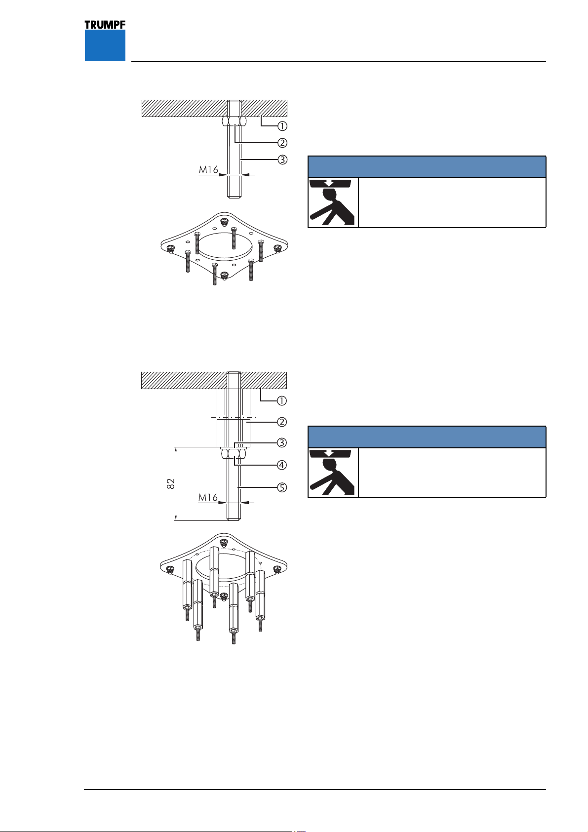
Figure 4 6.1 Installing Threaded Bolts on the
Ceiling Anchor Plate
1. Screw the hexagon nuts 2 onto the threaded bolts
3 (length 110mm) at intervals of min. 25mm.
1WARNING
Danger of the lighting system falling
Screw threaded bolt 3 into the ceiling
anchor plate 1 as far as it will go.
2. Screw six threaded bolts 3 as far as they will go
into the ceiling anchor plate 1.
Tightening the hexagon nuts:
3. Tighten the hexagon nuts 2 uniformly to 195Nm.
Figure 5
6.2 Installing Optional Spacers on the
Ceiling Anchor Plate
The length of the six spacers depends on the specific
order.
1WARNING
Danger of the lighting system falling
Screw threaded bolt 3 into the ceiling
anchor plate 1 as far as it will go.
1. Screw six threaded bolts 5 as far as they will go
into the ceiling plate 1.
2. Push the spacers 2 onto the threaded bolts 5
and put a washer 3 and a hexagon nut 4 on
each of them.
Tightening the hexagon nuts:
3. Tighten the hexagon nuts 4 to 195Nm.
• Check that the spacers 2 are securely in place.
7200681 Installation Instructions iLED US Lighting System – 07/07
19
Page 20
7 Installing the Ceiling Flange
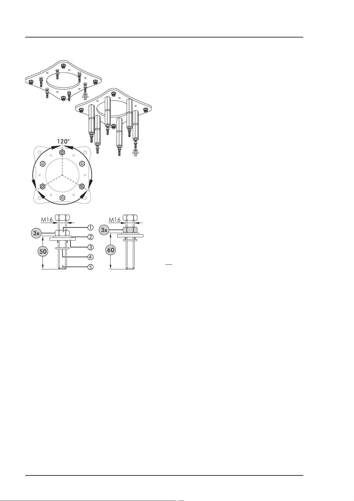
Figure 6 7.1 Preparing for Installation
Irrespective of the attachment elements specified in
“Section 6”, page 19, the following settings always
remain the same.
1. Screw three hexagon nuts 1, offset by 120° and
spaced 50mm, onto 3 threaded bolts 5.
• Screw the remaining 3 hexagon nuts 1 a little
higher e.g. 60 mm.
Aligning the hexagon nuts horizontally:
2. Horizontally align the three lower hexagon nuts 1
(spaced 50mm) using a spirit level.
Installing upper insulation:
3. Put a washer 2 and plastic insulating disk 3 on
the M16 threaded bolt 5 and secure using an
O-ring 4.
4. Repeat this procedure for the remaining 5
threaded bolts 5.
7.2 Installing Components on the Ceiling
Flange for the Power Supply using
Control Box Plates
If no interface plate is installed on the ceiling tube of
the ceiling flange, further components must be
installed on the ceiling flange depending on the
particular iLED lighting system variant.
Install the components on the floor beforehand
according to the following sections and then install
the ceiling flange as described in
page 25
.
“Section 7.3”,
20
7200681 Installation Instructions iLED US Lighting System – 07/07
Page 21
7 Installing the Ceiling Flange
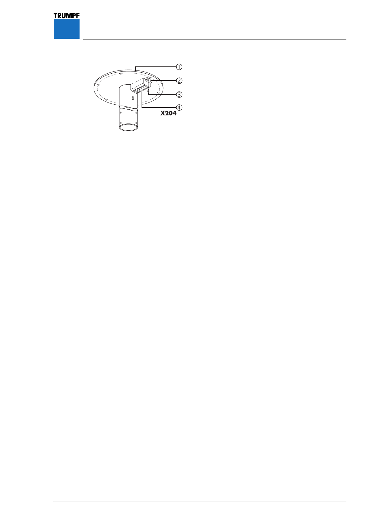
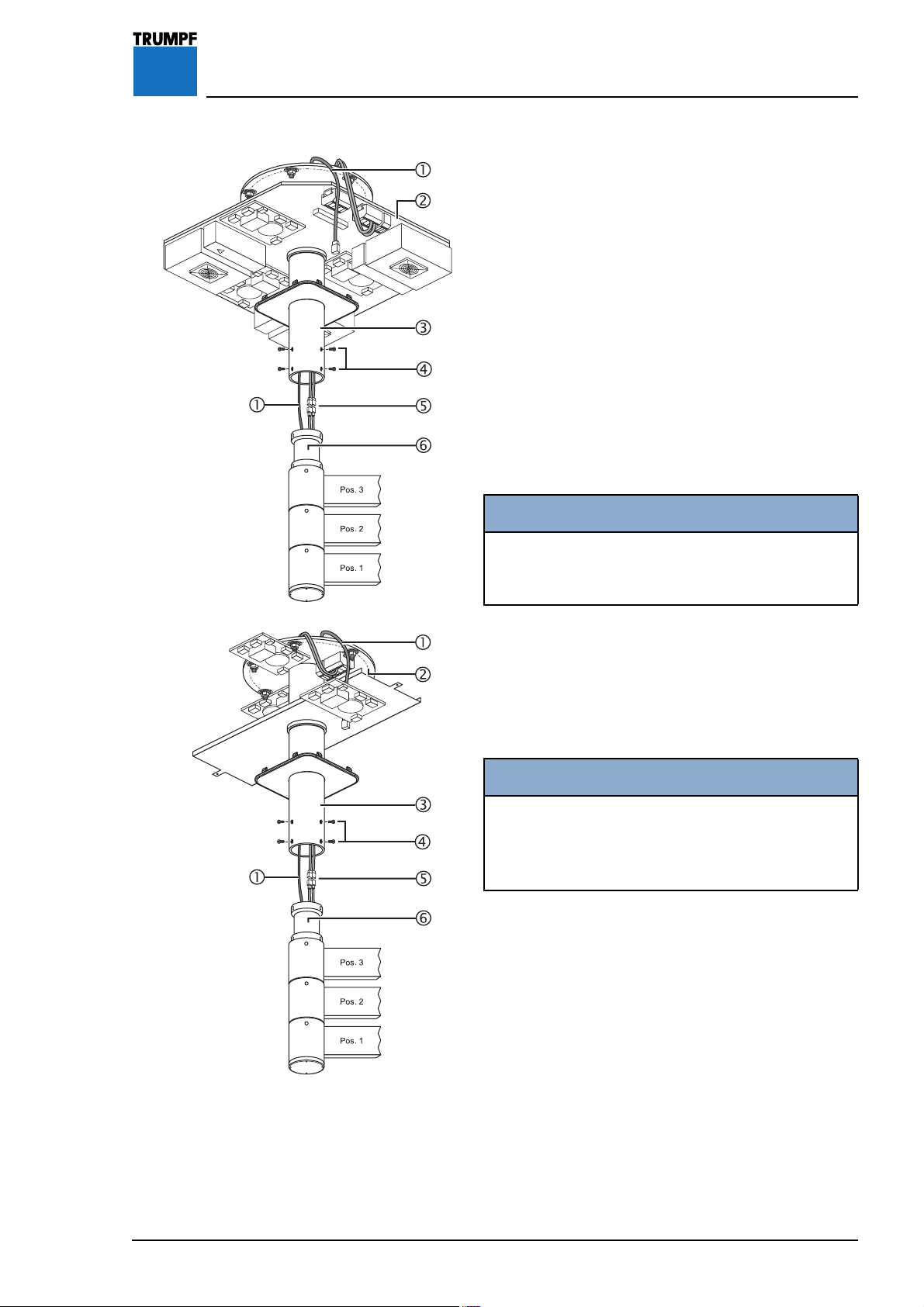
Figure 7 7.2.1 Variant: Light head without camera and
cable lengths of 1 - 20 m
Components to be installed:
• 1 top-hat rail and 1 terminal
1. Screw the top-hat rail 2 to the ceiling flange 1
using two M5 x 16mm socket head cap
screws 3.
2. Push the terminal 4 onto the top-hat rail 2 and
check that it is securely in place.
Electrical connection for iLED 5 / iLED 5 LCH / iLED 3
light heads:
• Route the cables into the control box plate in the
control box and connect according to circuit
diagram #4025890.
Electrical connection for iLED 3 LCH light head:
• Route the cables into the control box plate in the
control box and connect according to circuit
diagram #1431888.
7200681 Installation Instructions iLED US Lighting System – 07/07
21
Page 22
7 Installing the Ceiling Flange
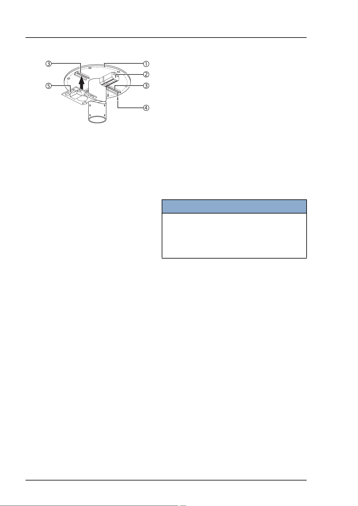
Figure 8 7.2.2 Variant: Light head without camera and
cable lengths of 21 - 50 m
Components to be installed:
• 1 top-hat rail and 1 terminal
• 1 top-hat rail and 1 filter board per light head
Installing the top-hat rails 3:
1. For each component, screw one top-hat rail 3 to
the ceiling flange 1 using two M5 x 16mm socket
head cap screws 4.
Installing the terminal 2:
2. Install one terminal 2 as described in “Section
7.2.1”, page 21, point 2et seqq.
Installing the filter board(s) 5:
NOTE
Filter boards:
• The filter board 5 (without Powerline additional
board) is required to boost the control signals
from the light head where the cables are
between 21 - 50 m in length.
3. For each light head, fit one filter board 5 on the
top-hat rail 3 and check that it is securely in
place.
Electrical connection for iLED 5 / iLED 5 LCH / iLED 3
light heads:
• Route the cables into the control box plate in the
control box and connect according to circuit
diagram #4025743.
Electrical connection for iLED 3 LCH light head:
• Route the cables into the control box plate in the
control box and connect according to circuit
diagram #1431892.
• Remove the jumpers in A and B on terminal X204.
22
7200681 Installation Instructions iLED US Lighting System – 07/07
Page 23
7 Installing the Ceiling Flange
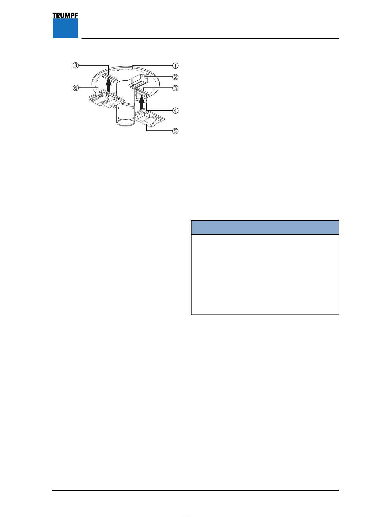
Figure 9 7.2.3 Variant: Light head with camera and cable
lengths of 1 - 50 m
Components to be installed:
• 1 top-hat rail and 1 terminal
• 1 top-hat rail and 1 filter board per light head
without camera
• 1 top-hat rail and 1 filter board with Powerline
additional board per light head with camera
Installing the top-hat rails 3:
1. For each component, screw one top-hat rail 3 to
the ceiling flange 1 using two M5 x 16mm socket
head cap screws 4.
Installing the terminal 2:
2. Install one terminal 2 as described in “Section
7.2.1”, page 21, point 2et seqq.
Installing the filter board(s) 5:
NOTE
Filter boards:
• The filter board with Powerline additional board
6 is required to boost the video signal from the
camera and the control signals from the light
head.
• The filter board 5 (without Powerline additional
board) is required to boost the control signals
from further light heads without camera where
the cables are between 21 - 50 m in length.
3. For each light head, fit one filter board 5 on the
top-hat rail 3 and check that it is securely in
place.
Install filter board with Powerline additional board 6:
4. Fit one filter board with Powerline additional board
6 for the camera connection on the top-hat rail
2 and check that it is securely in place.
7200681 Installation Instructions iLED US Lighting System – 07/07
Electrical connection for iLED 5 light head:
5. Route the cables into the control box plate in the
control box and connect according to the relevant
circuit diagram #4025895.
Electrical connection for iLED 3 LCH light head:
6. Route the cables into the control box plate in the
control box and connect according to circuit
diagram #1442682.
23
Page 24
7 Installing the Ceiling Flange
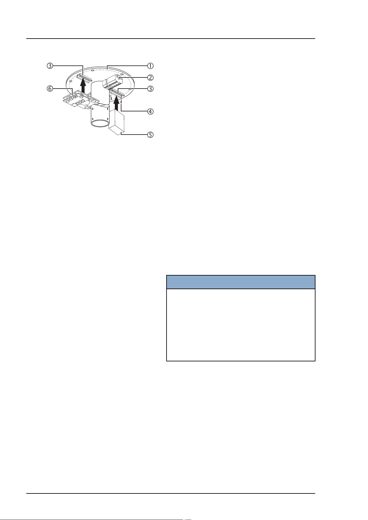
Figure 10 7.2.4 Variant with camera on separate pendant
Components to be installed:
• 1 top-hat rail and 1 terminal
• 1 top-hat rail and 1 power supply unit
• 1 top-hat rail and 1 filter board with Powerline
additional board
Installing the top-hat rails 3:
1. For each component, screw one top-hat rail 3 to
the ceiling flange 1 using two M5 x 16mm socket
head cap screws 4.
Installing the terminal 2:
2. Install one terminal 2 as described in “Section
7.2.1”, page 21, point 2et seqq.
Install power supply unit 5 for 230 V building power
supply:
3. Fit the power supply unit 5 for the camera on the
top-hat rail 3 and check that it is securely in
place.
Installing filter board with Powerline additional
board
6:
NOTE
Filter boards:
• The filter board with Powerline additional board
6 is required to boost the video signal from the
camera.
• If there are more light heads and cable lengths
of 21- 50m (an)other filter board(s) (without
Powerline additional board) must be installed to
boost the control signals from the light head.
4. Fit one filter board with Powerline additional board
6 for the camera connection on the top-hat rail
3 and check that it is securely in place.
Electrical connection for 230 V:
5. Connect cables for 230 V building power supply
according to circuit diagram #1432289.
24
Electrical connection for 24 V:
6. Connect cables for 24 V building power supply
according to circuit diagram #1440162.
7200681 Installation Instructions iLED US Lighting System – 07/07
Page 25
7 Installing the Ceiling Flange
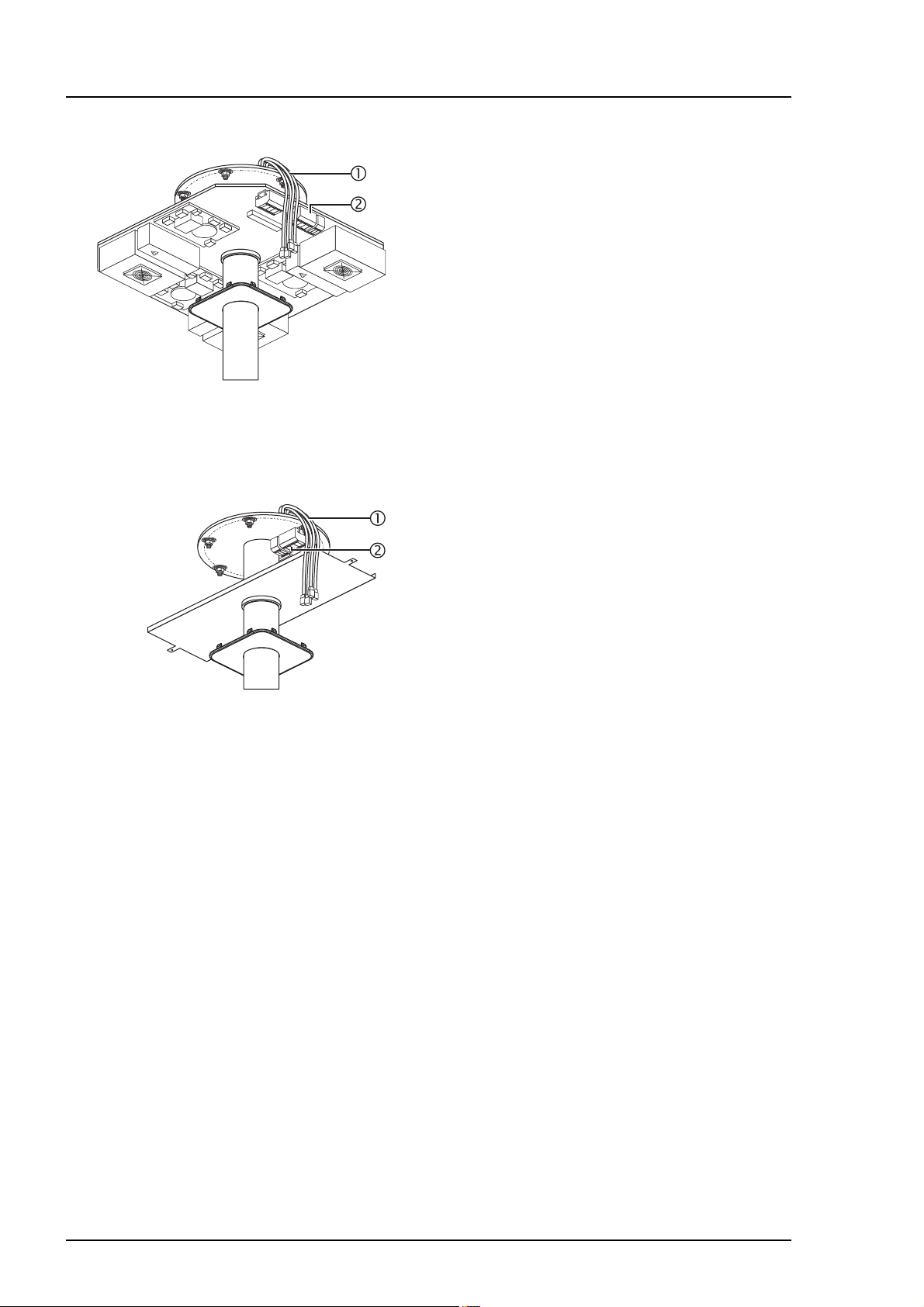
Figure 11 7.3 Installing the Ceiling Flange
1. Place the ceiling flange 2 on the 6 threaded bolts
1 and, using three hexagon nuts 7, turn and
move to the position of the non-aligned hexagon
nuts (spaced 60mm).
1WARNING
Danger of the lighting system falling
Screw the hexagon nuts 6 onto the
threaded bolts 1 as far as they will go.
Installing lower insulation:
2. Fit a plastic insulating disk 3, washer 4 and selflocking hexagon nut 5 on the three aligned
threaded bolts 1.
3. Gently tighten the three hexagon nuts 5.
Checking horizontal alignment:
4. Check the horizontal alignment of the ceiling
flange 2 and tighten the 3 self-locking hexagon
nuts 5 to 70Nm.
5. Screw the three upper hexagon nuts 8 downward
(spaced 60mm).
6. Remove the three hexagon nuts 7 (that were
previously fitted) from the threaded bolts 1, fit
them as described in point 2, and tighten to
70Nm.
• Check that the ceiling flange 2 is securely in
place.
7200681 Installation Instructions iLED US Lighting System – 07/07
25
Page 26
8 Installing an Interface Plate or Canopy Retainer Plate
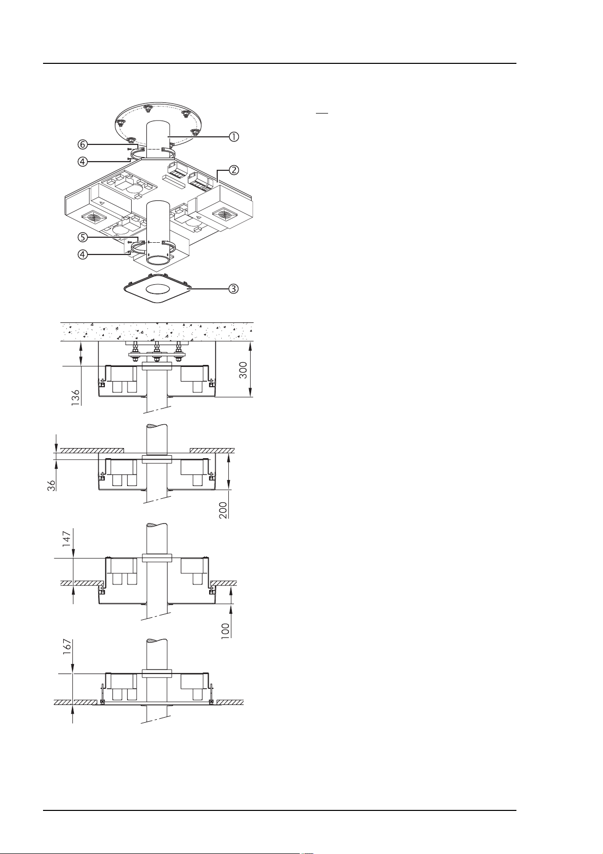
Figure 12 8.1 Installing an Interface Plate
If there is no interface plate installed, then the canopy
retainer plate must be installed as described in
“Section 8.2”, page 27.
Preparing to install the split rings
5/6:
1. Prepare two split rings 5/6 by screwing 2 socket
head cap screws and M8 x 40mm retaining
washers 5.
Adjusting the height of the interface plate:
2. Slide the split ring 6 onto the ceiling tube 1.
3. Adjust the height on the lower edge of the split ring
6 on the ceiling tube 1:
• With canopy:
- Canopy 300 = 136mm
- Canopy 200 = 36mm
- Canopy 100 = 147mm
• With ceiling screen:
- Ceiling screen = 167mm
4. Tighten the M8 x 40mm socket head cap screws
4 on the split ring 6.
Installing the interface plate:
5. Slide the interface plate 2 and the second split
ring 5 onto the ceiling tube 1 and align in
accordance with the ceiling recess.
6. Tighten the M8 x 40mm socket head cap screws
4 on the split ring 5.
7. Check that the interface plate 2 is securely in
place.
Installing the canopy cover 3:
8. Slide the canopy cover 3 onto the ceiling tube 1.
9. Prevent the canopy cover 3 from falling down
until the canopy or ceiling screen is installed.
26
7200681 Installation Instructions iLED US Lighting System – 07/07
Page 27
8 Installing an Interface Plate or Canopy Retainer Plate
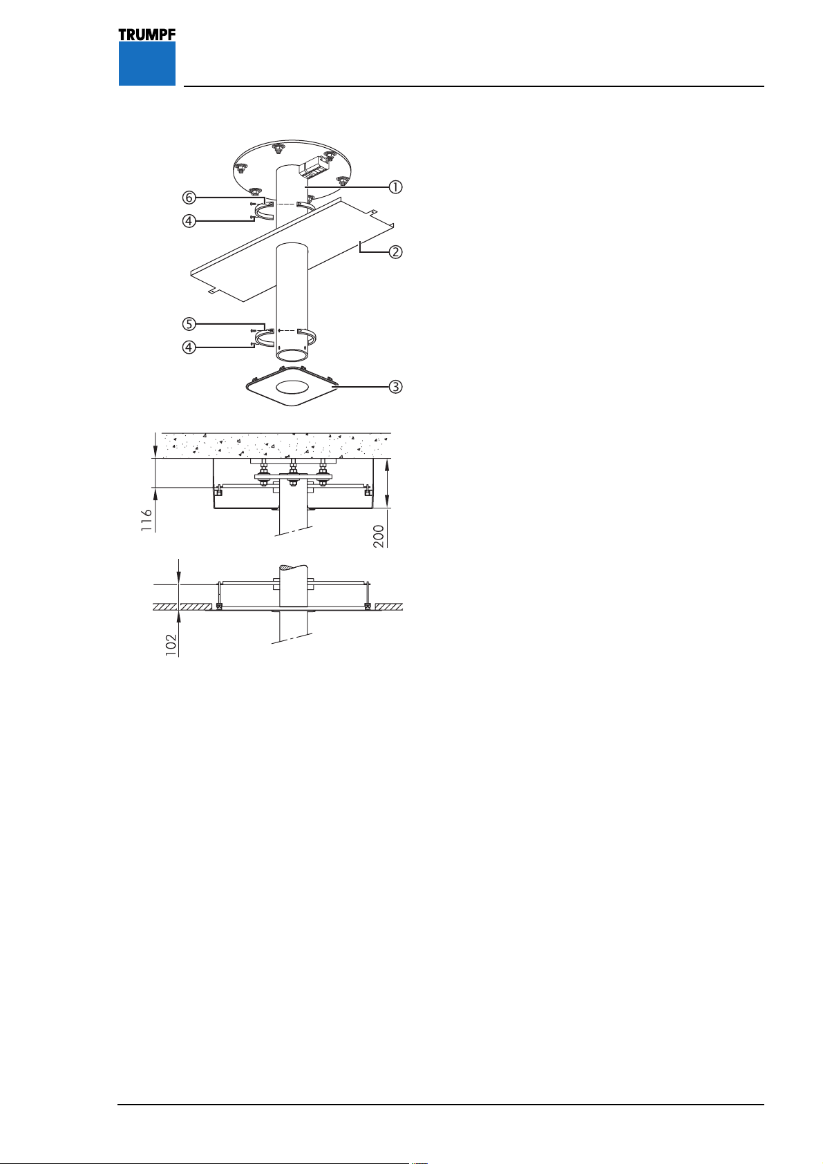
Figure 13 8.2 Installing a Canopy Retainer Plate
In order to later install the canopy and/or a ceiling
screen, the canopy retainer plate must be installed.
Preparing to install the split rings
5/6:
1. Prepare two split rings 5/6 by screwing 2 socket
head cap screws and M8 x 40mm retaining
washers 5 into each.
Adjusting the height of the canopy retainer plate:
2. Slide the split ring 6 onto the ceiling tube 1.
3. Adjust the height on the lower edge of the split ring
6 on the ceiling tube 1:
• With canopy:
- Canopy 200 = 116mm
• With ceiling screen:
- Ceiling screen = 102mm
4. Tighten the M8 x 40 mm socket head cap screws
4 on the split ring 6.
Installing the canopy retainer plate:
5. Slide the canopy retainer plate 2 and second split
ring 5 onto the ceiling tube 1 and align in
accordance with the ceiling recess.
6. Tighten the M8 x 40 mm socket head cap screws
4 on the split ring 5.
7. Check that the canopy retainer plate 2 is securely
in place.
7200681 Installation Instructions iLED US Lighting System – 07/07
Installing the canopy cover 3:
8. Slide the canopy cover 3 onto the ceiling tube 1.
9. Prevent the canopy cover 3 from falling down
until the canopy or ceiling screen is installed.
27
Page 28
9 Installing the Central Axis with Extension Arm
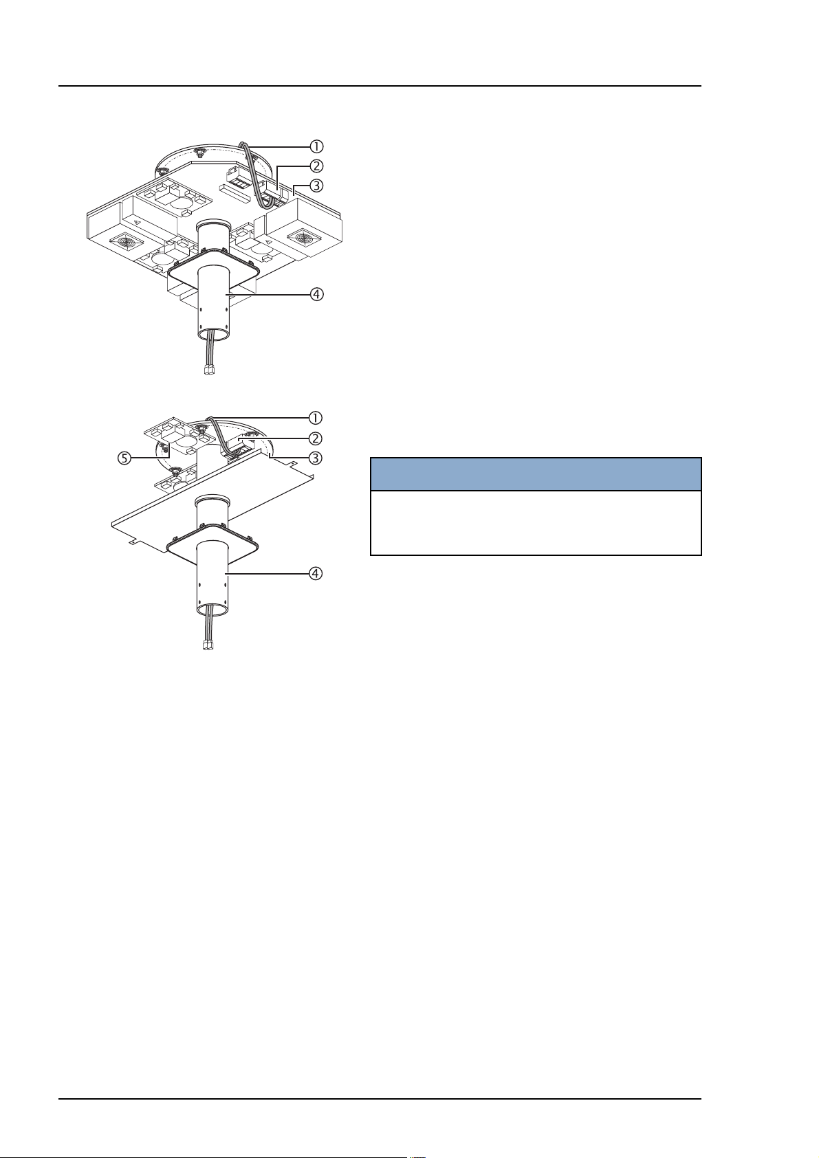
Figure 14 9.1 Routing Five-pole Cables for Light
Heads without Camera through the
Ceiling Tube
The separate 5-pole cables for light heads without
camera must first be routed through the ceiling tube
to the terminal on the interface plate or the ceiling
flange.
The 5-pole cables must be labeled to enable the light
heads without camera to be connected without any
risk of confusion.
Labeling five-pole cables:
1. Label the five-pole cables 1 with numbers on the
ends of the cable (depending on the number of
light heads without camera).
Routing five-pole cables through the ceiling tube:
NOTICE
Take care not to damage the cables
Carefully, without using a great deal of force,
route the cables 1 through the central tube 4.
2. Route the five-pole cables 1 through the ceiling
tube 4 to terminal (X201) 2 on the interface
plate or route them directly to the filter board (X9)
5 on the ceiling flange 3.
Connecting the five-pole cables to the interface plate:
• Connect the five-pole cables 1 in accordance with
the circuit diagrams:
- 230/24 V supply voltage #1431878,
- 24/24 V supply voltage) #1431885,
- 24 V supply voltage #1431887,
- 230 V supply voltage #1431882,
- 230/230V supply voltage #1431884,
and your cable labeling to terminal Klemme 2
on the interface plate.
28
Connecting five-pole cables to the ceiling flange:
1. Connect the five-pole cables 1 in accordance
with the circuit diagrams:
- connection lengths 1 - 20 m #4025890,
- connection lengths 21 - 50 m #4025743,
and your cable labeling to terminal 2 on the
ceiling flange 3.
7200681 Installation Instructions iLED US Lighting System – 07/07
Page 29
9 Installing the Central Axis with Extension Arm
Figure 15 9.2 Routing Seven-pole Cables for Light
Heads with Camera through the
Ceiling Tube
The 7-pole cables from the central axis must be
routed through the ceiling tube to the interface plate
or the ceiling flange.
The 7-pole cables from the central axis must be
labeled to enable the light heads with camera to be
connected without any risk of confusion.
Labeling seven-pole cables:
1. Label the seven-pole cables 1 with numbers on
the ends of the cable (depending on the number of
light heads without camera).
Routing seven-pole cables through the ceiling tube:
NOTICE
Take care not to damage the cables
Carefully, without using a great deal of force,
route the cables 1 through the central tube 3.
2. Route the seven-pole cables 1 through the ceiling
tube 3 to the interface plate or the ceiling
flange 3.
9.3 Installing the Central Axis
NOTICE
Make sure that the central axis is not tilted.
• It should be possible to install the central axis 6
without using a great deal of force.
• Take care not to damage the cables.
1. Using the lifting device, raise the central axis 6.
2. Connect 5-pole cable plugs 5 (see “Section 9.1”,
page 28).
3. Insert the central axis 6 into the ceiling tube 3
and screw it in place using 8 M6 x 10mm
countersunk head screws 4.
4. Tighten the eight M6 x 10mm countersunk head
screws 4 to 10Nm.
5. Check that the central axis 6 is securely in place.
6. Fit the eight M6 x 10 mm countersunk head screws
4 with plastic caps.
7200681 Installation Instructions iLED US Lighting System – 07/07
29
Page 30
10 Connecting the Cables
Figure 16 10.1 Connection Variants for Light Heads
without Camera
10.1.1 Connection to the interface plate
1. Connect the connecting cable plugs 1 in
accordance with your cable labeling in “Section
9.1”, page 28 and the circuit diagrams:
- 230/24 V supply voltage #1431878,
- 24/24 V supply voltage #1431885,
- 230 V supply voltage #1431882,
- 230/230 V supply voltage #1431884,
- iLED 3 LCH for all supply voltages #1431896
to terminal 2.
2. Connect the connecting cables (to be laid by
customer) to the terminals 2.
Figure 17 10.1.2 Connection via interface plate(s) where
cables are between 1 - 20m in length
1. Disconnect the connecting cable plugs 1.
2. Connect the connecting cables 1 in accordance
with your cable labeling in “Section 9.1”, page 28
and the
- circuit diagram #4025890,
- for iLED 3 LCH in accordance with circuit diagram
#1431888 to the terminals 2 on the ceiling
flange.
3. Connect the ground conductor to the terminal 2.
4. Connect the connecting cables (to be laid by
customer) from the control box plate(s) to the
terminals 2.
30
7200681 Installation Instructions iLED US Lighting System – 07/07
Page 31

10 Connecting the Cables
Figure 18 10.1.3 Connection via interface plate(s) where
cables are between 21 - 50m in length
1. Connect the connecting cable plugs 1 in
accordance with your cable labeling in “Section
9.1”, page 28 and in accordance with the circuit
diagram
- #4025743,
- for iLED 3 LCH in accordance with circuit diagram
#1431892,
to the filter board(s) 4 on the ceiling flange.
2. Connect the ground conductor to the terminal 2.
3. For each light head, connect one of the
connecting cables (W18) 3 supplied to the
terminal 2 and connect the plug to the
corresponding
4. Connect the connecting cables (to be laid by the
customer) from the control box plate(s) to the
terminals 2.
filter board 4.
7200681 Installation Instructions iLED US Lighting System – 07/07
31
Page 32

10 Connecting the Cables
Figure 19 10.2 Connection Variants for Light Heads
with Camera
10.2.1 Connection to the interface plate
1. Insert the connecting cable plugs 1 in
accordance with your cable labeling in “Section
9.1”, page 28 and the circuit diagram
- #1434128,
- for iLED 3 LCH in accordance with circuit diagram
#1442682,
into the Powerline additional board 4 on the
interface plate.
2. Connect the connecting cables (to be laid by
customer) to the terminals 2.
3. Plug the video signal cable for the camera into the
Powerline additional board 4.
4. Plug the connecting cable (Type RJ45) from the
controller (TruVidia) into the Powerline additional
board 4.
Figure 20 10.2.2 Connection via control box plate(s)
1. Insert the connecting cable plugs 1 in
accordance with your cable labeling in “Section
9.1”, page 28 and the circuit diagram
- #4025895,
- for iLED 3 LCH in accordance with circuit diagram
#1442682,
into the Powerline additional board 4 on the
ceiling flange.
2. Connect the connecting cables (to be laid by
customer) to the terminals 2.
3. For each light head, connect one of the
connecting cables (W18) 3 supplied to the
terminal 2 and connect the cable to the
corresponding filter board(s) 5.
4. Connect the ground conductor from the Powerline
additional board 4 to the terminal 2.
5. Plug the video signal cable for the camera
Powerline additional board 4.
6. Plug the connecting cable (Typ RJ 45) from the
controller (TruVidia) into the Powerline additional
board 4.
into the
32
7200681 Installation Instructions iLED US Lighting System – 07/07
Page 33

10 Connecting the Cables
Figure 21 10.3 Connection Variant for Camera on
Separate Pendant
10.3.1 Connection to the interface plate
1. Insert the connecting cable plugs 1 in
accordance with your cable labeling in “Section
9.1”, page 28 and the circuit diagrams:
- 230 V camera on separate pendant #1432289,
- 24 V camera on separate pendant #1440162,
- 230/24 V supply voltage #1431878,
- 24/24 V supply voltage #1431885,
- 230 V supply voltage #1431882,
- 230/230 V supply voltage #1431884,
into the Powerline additional board 4 on the
interface plate.
2. Connect customer's connecting cables to the
terminals 2.
3. Plug the video signal cable for the camera into the
Powerline additional board 4.
4. Plug the connecting cable (Type RJ45) from the
controller (TruVidia) into the Powerline additional
board 4.
Figure 22 10.3.2 Connection via control box plate(s)
1. Insert the connecting cable plugs 1 in
accordance with your cable labeling in “Section
9.1”, page 28 and the circuit diagrams:
- 230V camera on separate pendant #1432289,
- 24 V camera on separate pendant #1440162,
- connection lengths 1 - 20m #4025890,
- connection lengths 21 -50m #4025743,
into the Powerline additional board 6 on the
ceiling flange.
2. For 24 V building power supply: connect the
connecting cable (W18) 3 supplied to the
terminal 2 and connect the plug to the
corresponding
filter board 5.
3. For 230 V building power supply: connect the
power supply unit 4 with the connecting cable
(W24) to the terminal 2.
Connect the filter board with the connecting
cable (W25) to the power supply unit.
4. Plug the video signal cable for the camera into the
Powerline additional board 6.
5. Plug the connecting cable (Type RJ45) from the
controller (TruVidia) into the Powerline additional
board 6.
6. Connect the ground conductor from the Powerline
additional board 6 to the terminal 2.
7200681 Installation Instructions iLED US Lighting System – 07/07
33
Page 34

11 Installing a Spring Arm
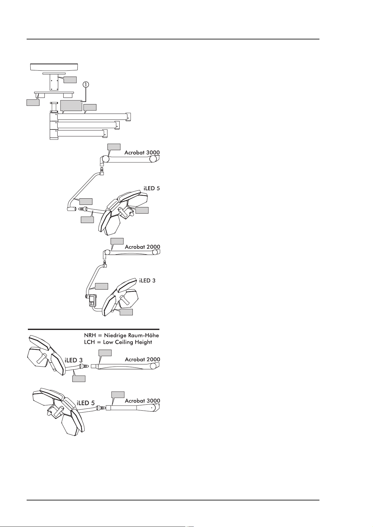
Figure 23 11.1 Spring Arm Versions
In general:
• one iLED 5 light head is installed on a
- Acrobat 3000 spring arm or
- Acrobat 3000 LCH spring arm (
Height),
• one iLED 3 light head is installed on a
- Acrobat 2000 spring arm or
- Acrobat 2000 LCH spring arm (
Height).
• the camera on the separate pendant is mounted on
the Acrobat 2000 spring arm,
• the vidiaPORT monitor holders are mounted on an
Acrobat 2000, Acrobat 3000 or Acrobat Space.
11.1.1 Spring arm equipment
For the different versions of the iLED lighting system,
e.g.: light head with/without camera or for the
vidiaPORT monitor installations, the spring arms
come with different equipment.
Low Ceiling
Low Ceiling
The simplest way of telling the application is to look at
the connecting spigot of the spring arm:
1. Spring arm with 5-pole rotating commutator 1 for
the installation of light heads (see “Section 11.3”,
page 36).
2. Spring arm with 7-pole cabling 2 for the
installation of light heads with camera or camera
on a separate pendant (see “Section 11.4”,
page 37).
3. Hollow spring arm 3 for routing cables for
monitor installations, e.g. vidiaPORT (see “Section
16”, page 50).
• The hollow spring arms 3 are rotation-limited to
approx. 330 degrees, to prevent the routed cables
from twisting.
• The range of the Acrobat Space spring arm can be
adjusted.
11.1.2 Spring arm adjustments
The tension for counterbalancing the weight of the
light head or monitor, the brake force and how to
adjust the spring arm height limit can be found in
“Section 18”, page 68.
34
7200681 Installation Instructions iLED US Lighting System – 07/07
Page 35

11 Installing a Spring Arm
Figure 24 11.2 Preparing for Installation for all Spring
Arm Variants
1. Undo the two screws 1 and remove the cover 2
on the extension arm 3.
1WARNING
Danger of the lighting system falling
Tak e ca r e
4 when removing.
2. Remove the circlip 4 from the spring arm 6.
3. Remove the disk 5 from the spring arm 6.
not to overextend the circlip
7200681 Installation Instructions iLED US Lighting System – 07/07
35
Page 36

11 Installing Spring Arms
Figure 25 11.3 Installing Spring Arm for Light Head
without Camera
Feature of the spring arms:
• 5-pole rotating commutator 6 in the connecting
spigot of the spring arm (see “Section 11.1”,
page 34).
Installing the spring arm:
1. Carefully pull the 5-pole plug 6 out of the
extension arm 3.
NOTICE
Raising the spring arm
Figure 26
• Only raise the spring arm 5
illustrated by the arrow
•
Never lift the spring arm by the cover panels 4.
2. Raise the spring arm 5 at the point
the arrow
and insert it into the extension arm 3.
at the point
.
indicated by
1WARNING
Danger of the lighting system falling
The circlip 1 must be fully engaged
with the groove in the pivot of the
spring arm.
3. Position the disk (1 piece) 2 and install the
circlip 1.
4. Check that the spring arm 5 is securely in place.
Connecting the plug:
NOTE
36
Using the grooves to position the plug
• The plug connector 9 has one narrow groove 7
and one wide groove 8.
• When connecting the plug 9, the grooves 7/8
must be aligned with the corresponding grooves
in the counterpart.
5. Carefully insert the plug 6 from above.
6. Check that the plug 6 is securely in place.
7. Install the cover as described in “Section 11.7”,
page 39.
7200681 Installation Instructions iLED US Lighting System – 07/07
Page 37

11 Installing Spring Arms
Figure 27 11.4 Installing Spring Arm for Light Head
with Camera
Feature of the spring arms:
• 7-pole cabling consisting of three threaded
connectors and a 6-pole plug in the connecting
spigot of the spring arm (see “Section 11.1”,
page 34).
Connecting the cables:
1. Carefully route the cables 7 into the extension
arm 3 out the top of the extension arm 3.
NOTICE
Raising the spring arm
• Only raise the spring arm 5
illustrated by the arrow.
Never lift the spring arm by the cover panels 4.
•
2. Raise the spring arm 5 at the point indicated by
the arrow and carefully route the cables 6 into
the spring arm 5 through the extension arm 3.
Installing the spring arm:
3. Insert the spring arm 5 into the extension arm 3.
at the point
1WARNING
Danger of the lighting system falling
The circlip 1 must be fully engaged
with the groove in the pivot of the
spring arm.
4. Position the disk (1 piece) 2 and install the
circlip 1.
5. Check that the spring arm 5 is securely in place.
Figure 28
7200681 Installation Instructions iLED US Lighting System – 07/07
Connecting the plugs:
6. Connect up the three threaded connectors 8
according to the color code.
7. Connect the 6-pole plug 9.
8. Carefully push the threaded connectors 8 and
6-pole plug 9 back into the extension arm 3
from above.
9. Install the cover as described in “Section 11.7”,
page 39.
37
Page 38

11 Installing Spring Arms
Figure 29 11.5 Installing Spring Arm for vidiaPORT
Monitor Installations
Feature of the spring arms:
• Hollow connecting spigot for routing cables (see
“Section 11.1”, page 34).
1WARNING
Sudden release of the Acrobat Space
spring arm
• If no monitor is mounted when the lock
is disengaged, the spring arm will
jump upward.
• Do not take out the locking pin 5
until the monitor is fully mounted.
Installing the spring arm:
1. Insert the spring arm 4 into the extension arm 3.
Only Acrobat Space spring arm: Adjust the arm
2.
stop as described in “Section 11.6”, page 38.
Figure 30
1WARNING
Danger of the lighting system falling
The circlip 1 must be fully engaged
with the groove in the pivot of the
spring arm.
3. Position the disk (1 piece) 2 and install the
circlip 1.
4. Check that the spring arm 4 is securely in place.
11.6 Adjusting Arm Stop on the Acrobat
Space Spring Arm
The arm stop limits Acrobat Space spring arm rotation
of the extension arm to approx. 330 degrees.
The range can be further limited by installing an extra
stop pin.
1. Check the arm stop of the spring arm in the
extension arm.
• The spring arm must not collide with nearby walls
or objects.
38
7200681 Installation Instructions iLED US Lighting System – 07/07
Page 39

11 Installing Spring Arms
Figure 31 11.7 Installing the Cover
Only for spring arms for vidiaPORT monitor
installations:
• Before installing the cover 2 push the cables into
the spring arm and extension arm.
Only for spring arms with 5-pole plug:
• The grub screws 3 in the cover 2 keep the 5-pole
plug 5 in place:
1WARNING
Electric shock
When installing the cover 2, make
sure that the grub screws 3 do not
damage the internal cables!
1. Position the cover 2 in such a way that the two
grub screws 3 are located in the cut-outs in the
plug 4.
Only for spring arms with 5-pole plug:
2.
Carefully turn the cover 2 with 5-pole plug 5
until the two screws 1 can be screwed in.
3. Screw on the cover 2 using two screws 1.
4. Check that the cover 2 is securely in place.
7200681 Installation Instructions iLED US Lighting System – 07/07
39
Page 40

12 Installing the Horizontal Bar on the iLED 5 Light Head
Figure 32 12.1 Installing the Horizontal Bar on the
iLED 5 Light Head without Camera
1. Unscrew one securing screw 3.
2. Unscrew two brake screws 2/4.
Connecting the plug:
NOTE
Using the grooves to position the plug
• The plug connector 5 has one narrow groove 7
and one wide groove 8.
• When connecting the plug 5, the grooves 7/8
must be aligned with the corresponding grooves
in the counterpart.
Installing the horizontal bar:
3. Precisely insert the horizontal bar 1 axially into the
light head's gimbal joint 6.
4. Screw in a securing screw 3.
5. Screw in two brake screws 2/4.
6. Check that the horizontal bar 1 is securely in
place.
7. Continue installation as described in “Section
13.1”, page 41.
Figure 33
12.2 Installing the Horizontal Bar on the
iLED 5 Light Head with Camera
1. Unscrew one securing screw 3.
2. Unscrew two brake screws 2/4.
Connecting the plug:
3. Connect the 6-pole plug 6.
4. Connect up the three threaded connectors 7
according to the color code.
5. Carefully push the 6-pole plug 6 and threaded
connectors 7 into the gimbal joint 1.
Installing the horizontal bar:
6. Precisely insert the horizontal bar 1 axially into the
light head's gimbal joint 5.
7. Screw in a securing screw 3.
8. Screw in two brake screws 2/4.
9. Check that the horizontal bar 1 is securely in
place.
10. Continue installation as described in “Section
13.4”, page 44.
40
7200681 Installation Instructions iLED US Lighting System – 07/07
Page 41

13 Installing the Light Head
Figure 34 13.1 Installing the Light Head without
Camera on the Acrobat 2000/3000
Spring Arm
The iLED 3 and iLED 5 light heads must be installed
on different spring arms.
1. Only Acrobat 3000 spring arm: unscrew the M10
x 8.6mm slotted brake screw 1.
2. Unscrew the M3 x 8 mm countersunk screw 7
and slide the sleeve 8 upward.
3. Screw the M3 x 8mm countersunk screw 7 back
in again to secure the sleeve 8.
4. Remove the locking segment 2.
Connecting the plug:
NOTE
Using the grooves to position the plug
• The plug connector 6 has one narrow groove 3
and one wide groove 4.
• When connecting the plug 5 the grooves 3/4
must be aligned with the corresponding grooves
in the counterpart.
5. Precisely insert the light head 5 axially into the
spring arm 9.
1WARNING
Danger of the light head falling
• If the wrong locking segment 2 is
fitted, the light head may fall.
• Only use an original locking segment
2 for the spring arm in question.
6. Insert the locking segment 2, unscrew the M3 x
8 mm countersunk screw 7 and slide the sleeve
8 downward.
1WARNING
7200681 Installation Instructions iLED US Lighting System – 07/07
Danger of the light head falling
• Secure the sleeve 8 with an M3 x
8 mm countersunk screw 7.
7. Screw in the M3 x 8mm countersunk screw 7.
Only Acrobat 3000 spring arm: screw in the M10
8.
x 8.6mm slotted brake screw 1.
9. Check that the light head 5 is securely in place.
10. Adjust the spring arm as described in “Section
18”, page 68.
41
Page 42

13 Installing the Light Head
Figure 35 13.2 Installing the iLED 3 Light Head
without Camera on the Acrobat 2000
LCH Spring Arm
1. Unscrew the brake screw 7 on the underside of
the sleeve 4.
2. Turn the sleeve 4 90 degrees and unscrew the
first end device securing screw 2.
3. Turn the sleeve 4 180 degrees and unscrew the
second end device securing screw 2.
Connecting the plug:
NOTE
Using the grooves to position the plug
• The plug connector 3 has one narrow groove 8
and one wide groove 9.
• When connecting the plug 3 the grooves 8/9
must be aligned with the corresponding grooves
in the counterpart.
Installing the light head:
4. Precisely insert the light head 1 axially into the
spring arm 5.
1WARNING
Danger of the light head falling
• Secure the light head 1 with two end
device securing screws 2.
5. Screw in two end device securing screws 2.
6. Screw in one brake screw 7.
7. Check that the light head 1 is securely in place.
8. Adjust the spring arm as described in “Section
18”, page 68.
42
7200681 Installation Instructions iLED US Lighting System – 07/07
Page 43

13 Installing the Light Head
Figure 36 13.3 Installing the iLED 5 Light Head
without Camera on the Acrobat 3000
LCH Spring Arm
1. Carefully take out the sleeve securing screw 7
and slide the sleeve 5 backward.
2. Unscrew the two end device securing screws 4.
3. Unscrew the two brake screws 3.
Connecting the plug:
NOTE
Using the grooves to position the plug
• The plug connector 2 has one narrow groove 8
and one wide groove 9.
• When connecting the plug 2, the grooves 8/9
must be aligned with the corresponding grooves
in the counterpart.
Installing the light head:
4. Precisely insert the light head 1 axially into the
spring arm 6.
5. Screw in two end device securing screws 4.
6. Screw in the two brake screws 3.
1WARNING
Danger of the light head falling
• Secure the sleeve 5 with the sleeve
securing screw 7.
7. Carefully slide the sleeve 5 forward and screw in
the sleeve securing screw 7.
8. Check that the light head 1 is securely in place.
9. Adjust the spring arm as described in “Section
18”, page 68.
7200681 Installation Instructions iLED US Lighting System – 07/07
43
Page 44

13 Installing the Light Head
Figure 37 13.4 Installing the Light Head with Camera
on the Acrobat 2000/3000 Spring Arm
The iLED 3 and iLED 5 light heads must be installed
on different spring arms.
1. Only Acrobat 3000 spring arm: unscrew the M10
x 8.6mm slotted brake screw 1.
2. Unscrew the M3 x 8mm countersunk screw 6
and slide the sleeve 7 upward.
3. Screw the M3 x 8mm countersunk screw 6 back
in again to secure the sleeve 7.
4. Remove the locking segment 2.
Connecting the plug:
5. Connect up the three threaded connectors 3
according to the color code.
6. Connect the 6-pole plug 4.
7. Carefully push the screw connectors 3 and the
6-pole plug 4 into the spring arm 8.
Installing the light head:
8. Precisely insert the light head 1axially into the
spring arm 8.
9. Insert the locking segment 2, unscrew the M3 x
8mm countersunk screw 6 and slide the
sleeve 7 downward.
1WARNING
Danger of the light head falling
• Secure the sleeve 7 with an M3 x
8 mm countersunk screw 6.
10. Screw in the M3 x 8mm countersunk screw 6.
Only Acrobat 3000 spring arm: screw in the M10
11.
x 8.6mm slotted brake screw 1.
12. Check that the light head 5 is securely in place.
13. Adjust the spring arm as described in “Section
18”, page 68.
Mounting the counterweight for the camera:
14. Connect the counterweight for the camera as
described in “Section 15.1”, page 48.
44
7200681 Installation Instructions iLED US Lighting System – 07/07
Page 45

13 Installing the Light Head
Figure 38 13.5 Installing the iLED 3 Light Head with
Camera on the Acrobat 2000 LCH
Spring Arm
1. Unscrew the brake screw 6 on the underside of
the sleeve 3.
2. Turn the sleeve 3 90 degrees and unscrew the
first end device securing screw 2.
3. Turn the sleeve 3 180 degrees and unscrew the
second end device securing screw 2.
Connecting the plug:
4. Connect the six-pole plug 7.
5. Connect up the three threaded connectors 8
according to the color code.
6. Carefully push the six-pole plug 7 and threaded
connectors 8 into the spring arm 4.
Installing the light head:
7. Precisely insert the light head 1 axially into the
spring arm 4.
1WARNING
Danger of the light head falling
• Secure the light head 1 with two end
device securing screws 2.
8. Screw in two end device securing screws 2.
9. Screw in one brake screw 6.
10. Check that the light head 1 is securely in place.
11. Adjust the spring arm as described in “Section
18”, page 68.
Mounting the counterweight for the camera:
12. Connect the counterweight for the camera as
described in “Section 15.1”, page 48.
7200681 Installation Instructions iLED US Lighting System – 07/07
45
Page 46

13 Installing the Light Head
Figure 39 13.6 Installing the iLED 5 Light Head with
Camera on the Acrobat 3000 LCH
Spring Arm
The iLED 3 and iLED 5 light heads must be installed
on spring arms with different tension. See
4.1”, page 16
which.
for which serial number goes with
1. Carefully take out the sleeve securing screw 6
and slide the sleeve 4 backward.
2. Unscrew the two brake screws 2.
Connecting the plug:
3. Connect the six-pole plug 7.
4. Connect up the three threaded connectors 8
according to the color code.
5. Carefully push the six-pole plug 8 and threaded
connectors 7 into the spring arm 5.
“Section
Installing the light head:
6. Precisely insert the light head 1 axially into the
spring arm 5.
7. Screw in two end device securing screws 3.
8. Screw in the two brake screws 2.
1WARNING
Danger of the light head falling
• Secure the sleeve 4 with the sleeve
securing screw 6.
9. Carefully slide the sleeve 4 forward and screw in
the sleeve securing screw 6.
10. Check that the light head 1 is securely in place.
11. Adjust the spring arm as described in “Section
18”, page 68.
Mounting the counterweight for the camera:
12. Connect the counterweight for the camera as
described in “Section 15.1”, page 48.
46
7200681 Installation Instructions iLED US Lighting System – 07/07
Page 47

14 Installing Camera on Separate Pendant
Figure 40 14.1 Installing Camera on Separate
Pendant on the Acrobat 2000
Spring Arm
1. Unscrew the M3 x 8mm countersunk screw 5
and slide the sleeve 6 upward.
2. Screw the M3 x 8mm countersunk screw 5 back
in to secure the sleeve 6.
3. Remove the locking segment 1.
Connecting the plug:
4. Connect up the three threaded connectors 2
according to the color code.
5. Connect the six-pole plug 3.
6. Carefully push the threaded connector 2and the
6-pole plug 3 into the spring arm 7.
Installing the light head:
7. Precisely insert the camera yoke 4 axially into the
spring arm 7.
8. Insert the locking segment 1, unscrew the
M3 x 8mm countersunk screw 6 and slide the
sleeve 6 downward.
1WARNING
Danger of the camera system falling
• Secure the sleeve 6 with an M3 x
8mm countersunk screw 5.
9. Screw in the M3 x 8mm countersunk screw 5.
10. Check that the camera 5 is securely in place.
11. Adjust the spring arm as described in “Section
18”, page 68.
Mounting the counterweight for the camera:
12. Connect the counterweight for the camera as
described in “Section 15.1”, page 48.
7200681 Installation Instructions iLED US Lighting System – 07/07
47
Page 48

15 Connecting/Disconnecting Counterweight
Figure 41 15.1 Connecting the Counterweight
The spring arm counterbalances the weight of the
light head with camera or camera on a separate
pendant, to keep the camera still wherever it is
positioned. To counterbalance the changed weight
ratios when the camera is taken off, a counterweight
must be connected.
1. Slide the bayonet locking device into position 1
to free up the three holes 3 in the base plate 2.
2. Align the counterweight 7 in such a way that the
three bayonet pins 6 and the two centring pins 5
of the camera mount 4 line up with the holes 3
in the base plate 2.
• The camera connectors will then also be correctly
aligned.
3. Attach the counterweight 7 to the camera mount
4 and secure.
Slide the bayonet locking device to position 8.
• Line up the two red marks.
4. Check that the counterweight 7 is securely in
place.
48
7200681 Installation Instructions iLED US Lighting System – 07/07
Page 49

15 Connecting/Disconnecting Counterweight
Figure 42 15.2 Disconnecting the Counterweight
1. Slide the bayonet locking device into position 1
to free up the three holes 3 in the base plate 2.
CAUTION
The light head moves upward of its
own accord
When taking off the counterweight 6
the light head may move upward of its
own accord:
• Hold onto the light head when taking
off the counterweight 6.
• Then raise the light head slowly and
release it.
2. Hold onto the light head and take the
counterweight 7 off the light head.
3. Raise the light head slowly and release it.
7200681 Installation Instructions iLED US Lighting System – 07/07
49
Page 50

16 Installing the vidiaPORT Monitor Attachments
Figure 43 16.1 Special features
Cable routing:
When installing the vidiaPORT monitor attachments
the cables for the monitor must be routed through the
pendant system (spring arm, extension arm and
ceiling tube).
The vidiaPORT monitor attachments must only be
installed in the lowest and/or highest extension arm
position (Pos. 1 or Pos. 3 in the diagram).
Arm stop:
To prevent the cables from twisting, the extension arm
positions 1 or 3 have an arm stop function, which
limits the extension arm swivelling range to approx.
330 degrees.
Figure 44 16.2 vidiaPORT Versions
The different vidiaPORT versions can be mounted on
different spring arms with different load capacities.
Which spring arm the vidiaPORT version is installed
on depends on the monitor weight and the diameter
required to route the cables.
The following list shows you the features of the
individual spring arms:
• Acrobat 2000:
- Load capacity = up to max.21 kg
- Cable duct = max.2 x 9mm
- Narrowest point in cross-section = 160mm
2
• Acrobat 3000:
- Load capacity = up to max.30 kg
- Cable duct = max.1 x 9mm + 1 x 6 mm
+ 2 x 5mm
- Narrowest point in cross-section = 384mm
2
• Acrobat Space:
- Load capacity = up to max.40 kg
- Cable duct = max.2 x 12mm + 2 x 6.5mm
- Narrowest point in cross-section = 450mm
2
50
The cable duct can be further restricted by the
vidiaPORT monitor adapter, the drill hole in the
ceiling tube and the diameter of the duct in the
central axis and must be checked in each case.
“Figure 44”, page 50 shows you the possible
configurations of each vidiaPORT version on the
respective spring arm.
7200681 Installation Instructions iLED US Lighting System – 07/07
Page 51

16 Installing the vidiaPORT Monitor Attachments
Figure 45 16.3 Routing Cables through the vidiaPORT
Monitor Adapter
To make it easier to route the power, data and
potential equalization lines, the vidiaPORT monitor
adapters Single and Duo can be removed at the
swivel joint.
Removing the swivel joint:
1. Undo the M4 x 10mm grub screw D.
2. Hold onto the monitor carrier C, unscrew the M8
x 45mm countersunk screw 9 and remove the
monitor carrier C.
• Keep the M8 x 45mm countersunk screw 9,
pressure disk 8, two anti-friction disks B and
sleeve A in a safe place.
Routing the cables:
The power, data and potential equalization lines used
must comply with the currently applicable regulations
for their specific application. See “Section 16.2”,
page 50 for the maximum cable duct sizes.
1WARNING
Electric shock – danger
If the 230 V (120 V) power lines are
damaged, the iLED lighting system is
live:
• At the swivel joint, all cables must be
laid in the spiral wrap supplied.
• Route in the power lines without
twisting or kinking them,
• Do not damage the cable insulation.
3. Cut the two potential equalization lines 6
3.5 mm² (not included in scope of supply) to
length and fit with ground shoes:
Cable 1: from the grounding point of the spring
•
arm to the connection point 4.
Cable 2: from connection point 5 to connection
•
point 7.
4. Lay and connect the potential equalization lines 6
according to “Figure 45”, page 51.
5. Check that the potential equalization lines 6 are
securely in place.
6. Continue installation as on next page.
7200681 Installation Instructions iLED US Lighting System – 07/07
51
Page 52

16 Installing the vidiaPORT Monitor Attachments
Figure 46 16.3 Cont'd
7. Route the power lines through the spigot 1 and
through the support tube 2.
8. Route the power lines through the monitor carrier
E and out through the opening 3 in the side.
9. At the swivel joint, insert all the lines in the spiral
wrap supplied.
10. Lay the spiral wrap with the lines in the swivel joint
in such a way that the lines cannot fray or get
pinched.
Installing the swivel joint:
11. Insert two anti-friction disks B into the side of the
sleeve A.
12. Insert the monitor carrier E into the support tube
2.
13. Put the pressure disk 8 on the M8 x45 mm
countersunk screw 9.
14. Slightly tighten the M8 x 45 mm countersunk screw
9.
15. Tighten the M4 x 10mm grub screw D to prevent
the M8 x 45mm countersunk screw 9 from
loosening.
52
7200681 Installation Instructions iLED US Lighting System – 07/07
Page 53

16 Installing the vidiaPORT Monitor Attachments
Figure 47 16.4 Routing Cables through the VESA 100
Adapter
1WARNING
Electric shock – danger
If the 230 V (120 V) power lines are
damaged, the iLED lighting system is
live:
• Route in the power lines without
twisting or kinking them,
• Do not damage the cable insulation.
1. From below, route the power lines 4 through the
installation hole 3 into the Vesa 100 adapter 2.
2. Route the power lines 4 out through the spigot 1
of the Vesa 100 adapter 2.
Figure 48
16.5 Installing the vidiaPORT Monitor
Adapter on the Acrobat 2000/3000
Spring Arm
1. Only Acrobat 3000 spring arm: Unscrew the M10
x 8.6mm slotted brake screw 2.
2. Unscrew the M3 x 8mm countersunk screw 6
and slide the sleeve 7 upward.
3. Screw the M 3 x 8mm countersunk screw 6 back
in again to secure the sleeve 8.
4. Remove the locking segment 3.
Laying the power lines:
1WARNING
Electric shock – danger
If the 230 V (120 V) power lines are
damaged, the iLED lighting system is
live:
• Route in the power lines without
twisting or kinking them,
• Do not damage the cable insulation.
7200681 Installation Instructions iLED US Lighting System – 07/07
5. Route the power lines 5 through the spring arm
attachment to the parallel guide 1 according to
“Figure 49”, page 54.
6. Cont'd on next page.
53
Page 54

16 Installing the vidiaPORT Monitor Attachments
Figure 49 16.5 Cont'd
7. Precisely insert the vidiaPORT monitor adapter 4
axially into the spring arm 8.
1WARNING
Danger of the vidiaPORT monitor
adapter falling
• If the wrong locking segment 3 is
fitted, the vidiaPORT monitor adapter
4 may fall.
• Only use an original locking segment
3 for the spring arm in question.
8. Insert the locking segment 3, unscrew the
M3 x 8 mm countersunk screw 6 and slide the
sleeve 7 downward.
1WARNING
Danger of the vidiaPORT monitor
adapter falling
Secure the sleeve 7 with an
M3 x 8 mm countersunk screw 6.
9. Screw in the M3 x 8 mm countersunk screw 6.
Only Acrobat 3000 spring arm: screw in the M10
10.
x 8.6mm slotted brake screw 2.
11. Check that the vidiaPORT monitor adapter 4 is
securely in place.
12. Secure the power lines 5 in the parallel guide 1
of the spring arm using 5 cable ties.
13. Install the two cover panels 9.
14. Adjust the spring arm as described in “Section
18”, page 68.
54
7200681 Installation Instructions iLED US Lighting System – 07/07
Page 55

16 Installing the vidiaPORT Monitor Attachments
Figure 50 16.6 Installing the vidiaPORT Duo Monitor
Attachment on the Acrobat Space
Spring Arm
1WARNING
Sudden release of the Acrobat Space
spring arm
• If no monitor is mounted when the lock
is disengaged, the spring arm will
jump upward.
• Do not take out the locking pin 5
until the monitor is fully mounted.
1. Unscrew the two M 4 Torx screws2 and take off
the spring plate 3.
2. Remove the locking segment 4.
Laying the power lines:
1WARNING
Electric shock – danger
If the 230 V (120 V) power lines are
damaged, the iLED lighting system is
live:
• Route in the power lines without
twisting or kinking them,
• Do not damage the cable insulation.
3. Route the power lines 7 through the spring arm
attachment to the tube 1 according to “Figure
50”, page 55.
4. Precisely insert the vidiaPORT monitor adapter 6
axially into the spring arm 8.
1WARNING
Danger of the vidiaPORT monitor
adapter falling
• If the wrong locking segment 4 is
fitted, the vidiaPORT monitor adapter
6 may fall.
• Only use an original locking segment
4 for the spring arm in question.
7200681 Installation Instructions iLED US Lighting System – 07/07
5. Cont'd on next page.
55
Page 56

16 Installing the vidiaPORT Monitor Attachments
Figure 51 16.6 Cont'd
6. Insert the locking segment 4.
1WARNING
Danger of the vidiaPORT monitor
adapter falling
• Secure the locking segment 4 with
the spring plate 3.
7. Position the spring plate 3 and tightly screw in 2
M4 Torx screws 2.
8. Check that the vidiaPORT monitor adapter 6 is
securely in place.
9. Ground the Acrobat Space spring arm as
described in “Section 16.7”, page 57.
56
7200681 Installation Instructions iLED US Lighting System – 07/07
Page 57

16 Installing the vidiaPORT Monitor Attachments
Figure 52 16.7 Grounding the Acrobat Space Spring
Arm
1WARNING
Electric shock – danger
If the insulation is defective, the
pendant system may be live:
• Ground the Acrobat Space spring
arm.
NOTE
Only for qualified staff
• Electrical connection may only be carried out by
electricians.
1. Strip the supplied ground conductor 2.5mm² 4
and connect to the grounding point 1 in the
extension arm 2.
2. Route the ground conductor 2.5mm² 4 through
the spring arm 3 and out the installation opening
8, cut to length, strip, and connect to the
grounding point in the spring arm 7.
3. Secure the power lines and ground conductor
2.5mm² 4 on the underside of the tube 6 at
intervals of 20cm using cable ties 5.
4. Do not install the cover panels 9 until
adjustments have been completed.
7200681 Installation Instructions iLED US Lighting System – 07/07
57
Page 58

16 Installing the vidiaPORT Monitor Attachments
Figure 53 16.8 Routing in Cables
1WARNING
Electric shock – danger
If the 230 V (120 V) power lines are
damaged, the iLED lighting system is
live:
• Route in the power lines without
twisting or kinking them,
• Do not damage the cable insulation.
1. Using a wire pull, route the power lines 3 through
the extension arm 4 according to Figure 53.
2. Draw the power lines 3 out of the
extension arm 2 according to Figure 53.
• Position 1 on the underside of the extension arm,
• Position 3 on the top of the extension arm,
3. Route the power lines 3 through the
ceiling tube 1.
• Make sure not to damage other power lines in the
central axis.
4. Connect the power lines 3 according to circuit
diagram #4024054.
5. Adjust the spring arm as described in “Section
18”, page 68.
58
7200681 Installation Instructions iLED US Lighting System – 07/07
Page 59
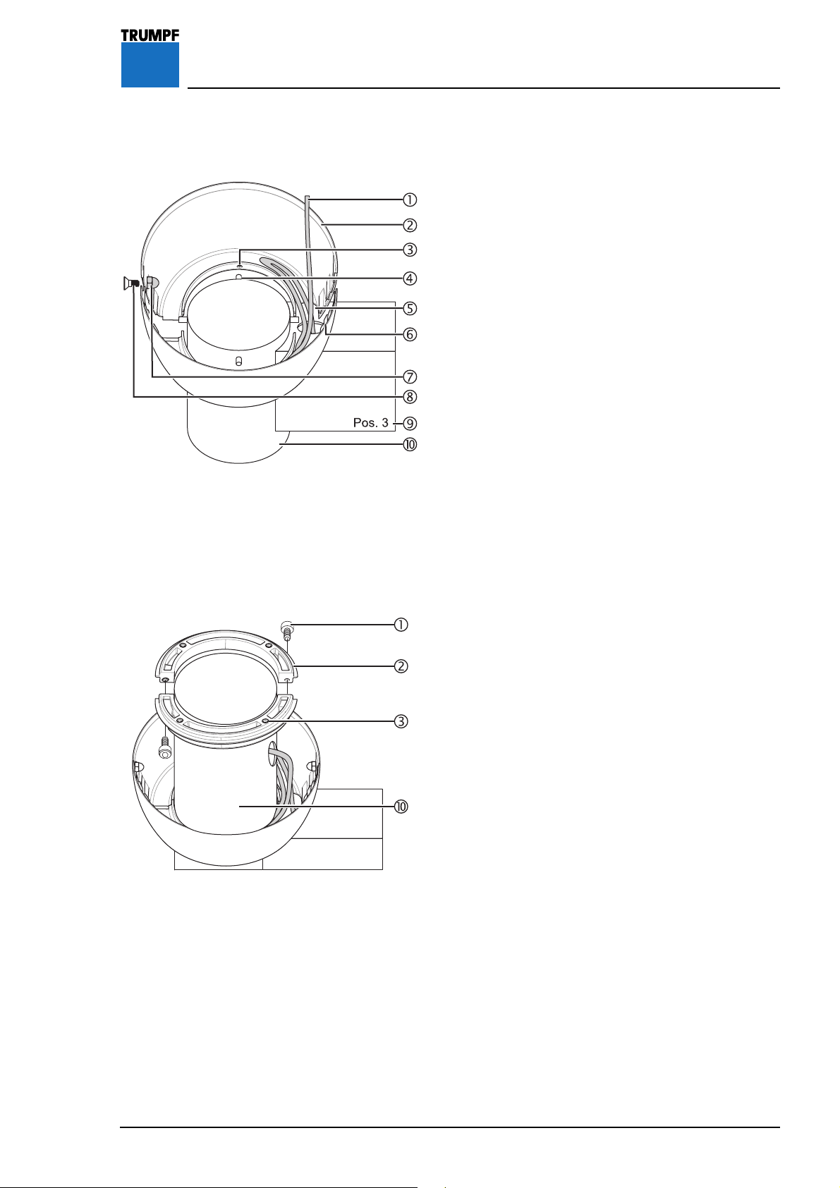
16 Installing the vidiaPORT Monitor Attachments
16.9 Installing the Canopy
Figure 54 Installing lower canopy halves:
1. Place the two canopy halves 2 on the uppermost
extension arm 9 in such a way that:
• the power lines 1 are located in the cut-outs 5,
• the 4 drill holes 3 in the canopy halves 2 sit on
the 4 pins 4 in the head of the extension arm A.
2. Connect up the canopy halves 2 with the
clips 6.
3. Connect up the canopy halves 2 using 2 M4 x
8 mm countersunk screws 8 and 2 M4 cap
nuts 7.
• The rounded M4 cap nuts 7 must sit inside the
canopy halves 2 in such a way as not to damage
the power lines 1.
4. Check that the canopy halves 2 are securely in
place.
5. Loop the power lines 1 inside the canopy halves
2 so that when swiveling the uppermost extension
arm 9, the power lines 1 are not subjected to
tensile stress.
6. Check that the power lines
1 can be swiveled.
Figure 55
Installing the split ring:
7. Place the split ring 2 around the ceiling tube A in
such a way that the 4 thread inserts 3 face
upward.
8. Screw the split ring 2 together using 2 M5 x
12 mm socket head cap screws 1.
9. Tighten the two M5 x 12 mm socket head cap
screws 1 so that the split ring 2 can barely be
moved axially on the ceiling tube A.
7200681 Installation Instructions iLED US Lighting System – 07/07
59
Page 60

16 Installing the vidiaPORT Monitor Attachments
Figure 56 Install upper canopy halves:
10. Place the two canopy halves 2 around the ceiling
tube A and connect them up using 2 M4 x 8mm
countersunk screws 4 and 2 M4 cap nuts 5.
• The rounded M4 cap nuts 5 must sit inside the
canopy halves 2 in such a way as not to damage
the power lines 6.
11. Screw the upper canopy halves 2 to the split ring
3 using 4 M5 x 10 mm round head cap screws
1.
12. Push the canopy halves 2 down until the top and
bottom canopy halves interlock.
13. Check function by swiveling the upper extension
arm 9.
• The interlocking canopy halves must swivel
smoothly and without resistance.
Figure 57
16.10 Installing the Ceiling Tube Cover
1. Place two springs 3 on the 2 pins 4.
2. Insert the two pins 4 into the drill holes 2 in the
extension arm 1.
3. Place the cover 5 on the two pins 4.
• The sealing lip in the cover 5 must sit in the groove
6 of the extension arm 1.
4. Check that the cover 5 is securely in place.
Removing the cover:
• To re mo v e t h e cover 5, press it in at the point
where the two pins 4 are located, and pull it down
and off.
60
7200681 Installation Instructions iLED US Lighting System – 07/07
Page 61

16 Installing the vidiaPORT Monitor Attachments
Figure 58 16.11 Installing the Flat-Screen Monitor
1WARNING
Sudden release of spring arm
Sudden unloading can cause the
spring arm to jump up and cause
serious injury:
• Before installing the TFT monitor,
move the spring arm to the highest
position.
1WARNING
Danger of falling pendant system
• Do not exceed the maximum spring
arm load capacity given in the
technical data.
1. Mount the TFT monitor 4 according to the
installation instructions from the monitor
manufacturer on the VESA 100 interface plate 2
of the vidiaPORT monitor adapter 1.
2. Check that the TFT monitor 4 is securely in
place.
3. Connect the power lines 3 according to the
installation instructions of the monitor
manufacturer.
4. Carry out functional test.
7200681 Installation Instructions iLED US Lighting System – 07/07
61
Page 62

17 Installing the Wall-Mounted Control Panel
Figure 59 17.1 Installing the Flush-Mounted Version
of the Wall-Mounted Control Panel
There are different wall-mounted control panels for
the iLED 3 and iLED 5 light heads. The wall-mounted
control panel for the iLED 5 light head has an extra
menu button 6.
Only where there is an external power supply:
To avoid installation problems, e. g. when drilling
through fire walls, we recommend you install
additional filter boards on the ceiling flange to
connect the wall-mounted ceiling panels.
Choosing connecting cables:
1. Choose the connecting cables for the particular
light head version under the following criteria.
Wall-mounted control panel connecting cable for
iLED 5 light head:
The connections in the supplied connecting cable 2 x
2 x 0.5mm², #4024903 (15m in length) are as
follows:
• 1 = white = + (VDC)
• 2 = brown = – (GND)
• 3 = green = ext A
• 4 = yellow = ext B
• Shield = PE (ground conductor symbol)
(see circuit diagram #4025854,)
If other connecting cables are used, the color coding
may be different. The connecting cable used must
have at least 2 twisted cable pairs with a minimum
cross section of 0.5mm². The shield is connected to
the ground conductor connection.
62
7200681 Installation Instructions iLED US Lighting System – 07/07
Page 63

17 Installing the Wall-Mounted Control Panel
Figure 60 17.1 Cont'd
Wall-mounted control panel connecting cable for
iLED 3 light head:
The connections in the supplied connecting cable 3 x
2 x 0.5mm², #1425421 (15m in length) are as
follows:
• 1 = white = + (VDC)
• 2 = brown = – (GND)
• 3 = green = ext A
• 4 = yellow = ext B
• Shield = PE (ground conductor symbol)
The gray/pink pair is not assigned (see circuit
diagram #4025857).
If other connecting cables are used, the color coding
may be different. The connecting cable used must
have at least 2 twisted cable pairs with a minimum
cross section of 0.5mm². The shield is connected to
the ground conductor connection.
Wall-mounted connecting cable for iLED 3 light head
on LCH spring arm:
The connections in the supplied connecting cable 3 x
2 x 0.5mm², #1425421 (15m in length) are as
follows:
• 1 = white = + (VDC)
• 2 = brown = – (GND)
• 3 = green = ext A
• 4 = yellow = ext B
• 5 = gray = int A
• 6 = pink = int B
• Shield = PE (ground conductor symbol)
(see circuit diagram #1431888,)
If other connecting cables are used, the color coding
may be different. The connecting cable used must
have at least 2 twisted cable pairs with a minimum
cross section of 0.5mm². The shield is connected to
the ground conductor connection.
7200681 Installation Instructions iLED US Lighting System – 07/07
63
Page 64

17 Installing the Wall-Mounted Control Panel
Figure 61 17.1 Cont'd
Preparing flush-mounted installation:
2. Route the connecting cables through one of the
openings 1 into the flush-mounted socket 2.
3. Install the flush-mounted socket 2 in the wall
recess and use suitable materal (e.g. plaster) to
secure it in the recess:
• Allow the material (e.g. plaster) to set,
4. Check that the flush-mounted socket 2 is securely
in place.
Connecting the wall-mounted control panel:
iLED 3 only:
Insert the adapter cable plug (#1412088) into the
board on the wall-mounted control panel. Connect
the adapter cable (#40245192) to the plug and
connect to the corresponding filter board in
accordance with the circuit diagram (#4025857).
iLED 5 only:
Connect the wall-mounted control in accordance with
the circuit diagram (#4025854).
5. Connect the connecting cables to the rear of the
panel 4 in accordance with the circuit diagrams:
- iLED 3 #4025857,
- iLED 5 #4025854.
6. Make the ground connection in the center of the
flush-mounted socket 2.
7. Relieve any strain on the connection cables in the
flush-mounted socket 2.
Complete installation:
8. Position the seal 3 and control panel 4 and
screw firmly in place using four M4 x 10mm
countersunk screws 5.
9. Check that the wall-mounted control panel is
securely in place.
iLED 5 only: Fit menu button 6.
10.
11. Carry out functional test.
64
7200681 Installation Instructions iLED US Lighting System – 07/07
Page 65

17 Installing the Wall-Mounted Control Panel
Figure 62 17.2 Installing the Surface-Mounted Version
of the Wall-Mounted Control Panel
There are different wall-mounted control panels for
the iLED 3 and iLED 5 light heads. The wall-mounted
control panel for the iLED 5 light head has an extra
menu button 6.
Only where there is an external power supply:
To avoid installation problems, e. g. when drilling
through fire walls, we recommend you install
additional filter boards on the ceiling flange to
connect the wall-mounted ceiling panels.
Choosing connecting cables:
1. Choose the connecting cables for the particular
light head version under the following criteria.
Wall-mounted control panel connecting cable for
iLED 5 light head:
The connections in the supplied connecting cable
2 x 2 x 0.5mm², #4024903 (15m in length) are as
follows:
• 1 = white = + (VDC)
• 2 = brown = – (GND)
• 3 = green = ext A
• 4 = yellow = ext B
• Shield = PE (ground conductor symbol)
(see circuit diagram #4025854,)
If other connecting cables are used, the color coding
may be different. The connecting cable used must
have at least 2 twisted cable pairs with a minimum
cross section of 0.5mm². The shield is connected to
the ground conductor connection.
7200681 Installation Instructions iLED US Lighting System – 07/07
65
Page 66

17 Installing the Wall-Mounted Control Panel
Figure 63 17.2 Cont'd
Wall-mounted control panel connecting cable for iLED
3 light head:
The connections in the supplied connecting cable 3 x
2 x 0.5mm², #1425421 (15m in length) are as
follows:
• 1 = white = + (VDC)
• 2 = brown = – (GND)
• 3 = green = ext A
• 4 = yellow = ext B
• Shield = PE (ground conductor symbol)
The gray/pink pair is not assigned (see circuit
diagram #4025857).
If other connecting cables are used, the color coding
may be different. The connecting cable used must
have at least 2 twisted cable pairs with a minimum
cross section of 0.5mm². The shield is connected to
the ground conductor connection.
Wall-mounted connecting cable for iLED 3 light head
on LCH spring arm:
NOTE
Special feature of iLED 3 LCH light head:
The connections in the supplied connecting cable 3 x
2 x 0.5mm², #1425421 (15m in length) are as
follows:
• 1 = white = + (VDC)
• 2 = brown = – (GND)
• 3 = green = ext A
• 4 = yellow = ext B
• 5 = gray = int A
• 6 = pink = int B
• Shield = PE (ground conductor symbol)
(see circuit diagram #1431888, #1431892 and
#45409)
Jumpers A and B must be removed from terminal
X204 (on the ceiling flange) (see “Section 7.2”,
page 20).
If other connecting cables are used, the color coding
may be different. The connecting cable used must
have at least 2 twisted cable pairs with a minimum
cross section of 0.5mm². The shield is connected to
the ground conductor connection.
66
7200681 Installation Instructions iLED US Lighting System – 07/07
Page 67

17 Installing the Wall-Mounted Control Panel
Figure 64 17.2 Cont'd
Preparing surface-mounted installation:
2. Check to ensure that there are no other cables or
pipes carrying electricity, gas or water below the
surface where the unit is to be installed.
3. Drill four attachment holes in the wall for the
surface-mounted socket 2.
Connecting the wall-mounted control panel:
iLED 3 only:
Insert the adapter cable plug (#1412088) into the
board on the wall-mounted control panel. Connect
the adapter cable (#40245192) to the plug and
connect to the corresponding filter board in
accordance with the circuit diagram (#4025857).
iLED 5 only:
Connect the wall-mounted control in accordance with
the circuit diagram (#4025854).
4. Route the connecting cables through one of the
openings 1 into the surface-mounted socket 2.
5. Screw the surface-mounted socket 2 to the wall
using 4 fixing screws.
• Check that the surface-mounted socket 2 is
securely in place.
6. Connect the connecting cables to the rear of the
panel 4 in accordance with the circuit diagrams:
- iLED 3 #4025857,
- iLED 5 #4025854.
7. Make the ground connection in the center of the
surface-mounted socket 2.
8. Relieve any strain on the connection cables in the
surface-mounted socket 2.
Complete installation
9. Position the seal 3 and control panel 4 and
screw firmly in place using four M4 x 10mm
countersunk screws 5.
10. Check that the wall-mounted control panel is
securely in place.
iLED 5 only: Fit menu button 6.
11.
12. Carry out functional test.
7200681 Installation Instructions iLED US Lighting System – 07/07
67
Page 68

18 Adjustments
Figure 65 18.1 Adjusting Spring Force on the Acrobat
2000/3000 and Acrobat 2000/3000
LCH Spring Arms
The spring arm has a spring to counterbalance the
weight of the light head. If the spring arm with light
head does not stay where it is positioned, the spring
force must be adjusted. Adjust the spring force so that
the spring arm with light head stays where it is
positioned.
1. Insert a size 5 hex head wrench into the hole
provided 1.
- Move the spring arm into its uppermost position to
relieve the pressure on it.
If the spring arm drops, the spring force is too low:
• Turn the size 5 hex head screw toward the +
(counterclockwise).
If the spring arm rises, the spring force is too high:
• Turn the size 5 hex head screw toward the –
(clockwise).
2. Carry out functional test.
Figure 66
18.2 Adjusting Spring Force on the Acrobat
Space Spring Arm
The spring arm has a spring to counterbalance the
weight of the light head. If the spring arm with light
head does not stay where it is positioned, the spring
force must be adjusted. Adjust the spring force so that
the spring arm with light head stays where it is
positioned.
1. Insert a size 5 hex head wrench into the hole
provided 1.
- Move the spring arm into its uppermost position to
relieve the pressure on it.
If the spring arm drops, the spring force is too low:
• Turn the size 5 hex head screw toward the +
(counterclockwise).
If the spring arm rises, the spring force is too high:
• Turn the size 5 hex head screw toward the –
(clockwise).
2. Carry out functional test.
68
7200681 Installation Instructions iLED US Lighting System – 07/07
Page 69

18 Adjustments
Figure 67 18.3 Adjusting Height Stop on the Acrobat
2000/3000 Spring Arms
When the unit ships from the factory the spring arm's
swivelling range in the horizontal plane is set by
default. The swivelling range can be extended
upward to approx. 45 degrees.
1. Insert a size 5 hex head wrench into the hole
provided 1.
- Pull down the spring arm to take the pressure off
the adjusting screw.
If you want to reduce the upward swivelling range:
• Turn the size 5 hex head screw toward the –
(clockwise).
If you want to extend the upward swivelling range:
• Turn the adjusting screw toward the +
(counterclockwise).
2. Carry out functional test.
Figure 68
18.4 Adjusting Height Stop on the Acrobat
Space Spring Arm
When the unit ships from the factory the spring arm's
upward and downward swivelling range is set to
40 degrees. The upward swivelling range can be
reduced to approx. 20 degrees.
1WARNING
Sudden release of the Acrobat Space
spring arm
• Do not take out the locking pin 3
until the light head / monitor is fully
mounted.
1. Pull out the locking pin 3.
2. Dismount the circlip 6 and remove the
stop pin 7.
3. Insert the stop pin 7 into the hole (20°) 4 and
secure with the circlip 6.
4. Check that the circlip 6 is securely in place.
5. Carry out functional test.
6. Insert the sealing flaps 5 into the guide rail of the
cover panels 2.
7. Screw on the two cover panels 2 with the four
Phillips screws 1.
8. Check that the cover panels 2 are securely in
place.
7200681 Installation Instructions iLED US Lighting System – 07/07
69
Page 70

18 Adjustments
Figure 69 18.5 Adjusting Height Stop on the Acrobat
2000 LCH Spring Arm
When the unit ships from the factory the spring arm's
swivelling range in the horizontal plane is set by
default. The swivelling range can be extended
upward to approx. 35 degrees.
1WARNING
Electric shock
• Isolate all poles of the iLED lighting
system from the power supply at the
mains.
• Ensure that the power supply cannot
be switched back on.
1. Isolate all poles of the iLED lighting system from the
power supply at the mains and ensure the power
supply cannot be switched on again.
2. Undo the two Phillips screws 4 and remove the
cover panels 3.
3. Adjust the adjusting nuts 2 in the hole provided
1 using the metal key.
4. Carry out functional test.
5. Position the cover panels 3 and screw in two
Phillips screws 4.
6. Check that the cover panels 3 are securely in
place.
Figure 70
18.6 Adjusting Height Stop on the Acrobat
3000 LCH Spring Arm
When the unit ships from the factory the spring arm's
upward and downward swivelling range is set to 40
degrees. The upward swivelling range can be
reduced to approx. 20 degrees.
1. Screw the stop screw 3 on both sides of the spring
arm out of the threaded hole 3 for the 40-degree
stop.
2. Screw the stop screw 3 on both sides of the spring
arm into the threaded hole for the 20-degree stop.
3. Carry out functional test.
4. Insert the sealing flaps 4 into the guide rail of the
cover panels 2.
5. Screw on the two cover panels 2 with the 2
Phillips screws 1.
6. Check that the cover panels 2 are securely in
place.
70
7200681 Installation Instructions iLED US Lighting System – 07/07
Page 71

18 Adjustments
Figure 71 18.7 Adjusting Brake Force on the Acrobat
3000 Spring Arm
If the light head does not stay in position of its own
accord, the brake force on the spring arm must be
adjusted.
1. Turn the brake screw 1 in the spring arm in the +
direction with a suitable slot head screwdriver to
increase the brake force.
2. Carry out functional test.
Brake screw used:
1 Brake screw with slot
M10 x 1 – 9 mm [1x]
#1378868
Figure 72
18.8 Adjusting Brake Force on the Acrobat
2000 LCH Spring Arm
If the light head does not stay in position of its own
accord, the brake force on the spring arm must be
adjusted.
1. Turn the brake screw 1 in the spring arm in the +
direction with a suitable slot head screwdriver to
increase the brake force.
2. Carry out functional test.
Brake screw used:
1 Brake screw with slot:
M10 x 1 – 11 mm [1x]
#4025239
7200681 Installation Instructions iLED US Lighting System – 07/07
71
Page 72

18 Adjustments
Figure 73 18.9 Adjusting Brake Force on the Acrobat
3000 LCH Spring Arm
If the light head does not stay in position of its own
accord, the brake force on the spring arm must be
adjusted.
1. Take out the sleeve securing screw 3 and slide the
sleeve 1 backward.
2. Turn the two brake screws 2 in the spring arm in
the + direction with a suitable slot head
screwdriver to increase the brake force.
3. Carry out functional test.
1WARNING
Danger of the light head falling
• Secure the sleeve 1 with the sleeve
securing screw 3.
4. Carefully slide the sleeve 1 forward and screw in
the sleeve securing screw 3.
Brake screw used:
2 Brake screw with slot
M10 x 1– 11 mm [2x]
#4025239
72
7200681 Installation Instructions iLED US Lighting System – 07/07
Page 73

18 Adjustments
Figure 74 18.10 Adjusting Brake Force on the
vidiaPORT Monitor Adapter
The brake force for stabilizing the TFT monitor 1 is
adjusted at the joint 2.
1. Undo the M4 x 10 mm grub screw 3.
To increase the brake force:
2. Screw in the M4 x 10 mm hex head screw 4 in a
clockwise direction and tighten to max. 20 Nm
with a wrench.
To reduce the brake force:
3. Unscrew the M8 x 45 mm hex head screw 4 in a
counterclockwise direction with a wrench.
4. Tighten the grub screw 3 to max. 4Nm.
Figure 75
18.11 Adjusting Brake Force on the VESA
100 Adapter
The brake force for stabilizing the TFT monitor 1 is
adjusted at the joint 2.
1. Undo the M4 x 10mm grub screw 4.
To increase the brake force:
2. Screw in the M8 x 45 mm hex head screw 3 in a
clockwise direction and tighten to max. 20Nm
with a wrench.
To reduce the brake force:
3. Unscrew the M8 x 45 mm hex head screw 3 in a
counterclockwise direction with a wrench.
4. Tighten the grub screw 4 to max. 4Nm.
7200681 Installation Instructions iLED US Lighting System – 07/07
73
Page 74

18 Adjustments
Figure 76 18.12 Adjusting Brake Force on the Camera
Adapter of the Separate Camera
The brake force for stabilizing the camera 1 is
adjusted on the brake shaft in the housing 3 of the
gimbal joint. It must only be adjusted when the camera
is mounted (with sterile handle).
1. Undo the three screws 8 and remove the housing
cover 2.
2. The adjusting screw 4 for the brake is locked with
a serrated washer. Bend the tooth 6 out of the
lock groove 7 to give you full access to the
adjusting screw.
To increase the brake force:
3. Turn the adjusting screw 4 on the brake shaft 5
in a clockwise direction using a size 27 wrench.
To reduce the brake force:
4. Turn the adjusting screw 4 on the brake shaft 5
counterclockwise using a size 27 wrench.
5. Re-lock the adjusting screw 4, by bending a
tooth of the serrated washer into the lock groove
7 (angle the tooth to the adjusting screw if this is
your only option on account of the rotation
position).
6. Put on the housing cover 2 and fasten using the
three screws 8.
74
7200681 Installation Instructions iLED US Lighting System – 07/07
Page 75

18 Adjustments
Figure 77 18.13 Adjusting Brake Force on the iLED
Lighting System
The brakes are set during installation. As with all
mechanical parts, brakes are subject to wear and
tear. If the light head no longer stays in position of its
own accord, the brake force must be adjusted via the
brake screws.
All brake screws are slotted screws. Adjust the brakes
in the order 1 - 4.
Brakes on the extension arm 1 and spring arm 2:
• Turn the two brake screws on both the extension
arm and spring arm in a clockwise direction with a
suitable slot-head screwdriver to increase the brake
force.
All other brakes 3- 5:
• Turn the three brake screws in a clockwise direction
with a suitable slot-head screwdriver to increase the
brake force.
Brake screws used:
1 Brake screw with slot
M12 x 1 – 30 mm [2x]
#1378864
2 Brake screw with slot (iLED 3)
M12 x 1 – 16 mm [2x]
#1378857
Brake screw with slot (iLED 5)
M12 x 1 – 21 mm [2x]
#1378866
3 Brake screw with slot (iLED 5)
M10 x 1 – 9 mm [1x]
#1378868
4 Brake screw with slot
M10 x 1 – 11 mm [2x]
#4025239
7200681 Installation Instructions iLED US Lighting System – 07/07
5 Brake screw with slot
(iLED 5 light head)
M10 x 1 – 15 mm [2x]
#4024587
75
Page 76

19 Installing the Canopy
Figure 78 19.1 Installing Brackets on the Interface
Plate
If there is no interface plate fitted, then the bracket
must be installed on the interface plate as described
in “Section 19.2”, page 77.
1. Screw two brackets 2, each with 2 M4 x 8mm
countersunk screws 3, to the interface plate 1.
2. Check that the two brackets 2 are securely in
place.
Installing the guide rails:
3. Screw two guide rails 5, each with 1 M6 x 30mm
socket head cap screw 4, to the brackets 2.
Fitting the attachment:
NOTE
Installation versions
• Depending on the installation version, for the 200
or 300mm canopy 8 an attachment 7,
• or a ceiling screen 6 (see “Figure 79”, page 77)
must be installed.
4. Fit two optional extension sections 7 onto the two
canopy halves 8.
76
7200681 Installation Instructions iLED US Lighting System – 07/07
Page 77

19 Installing the Canopy
Figure 79 19.2 Installing Brackets on the Canopy
Retainer Plate
1. Screw two brackets 2, each with 2 M4 x 8mm
countersunk screws 3, to the interface plate 1.
2. Check that the two brackets 2 are securely in
place.
Installing the guide rails:
3. Screw two guide rails 5, each with 1 M6 x 30mm
socket head cap screw 4, to the brackets 2.
Fitting the attachment:
NOTE
Installation versions
• Depending on the installation version, for the 200
or 300mm canopy 8 an attachment 7,
• or a ceiling screen 6 must be installed.
4. Fit two optional extension sections 7 onto the two
canopy halves 8.
7200681 Installation Instructions iLED US Lighting System – 07/07
77
Page 78

19 Installing the Canopy
Figure 80 19.3 Installing the Canopy
1. Place the rubber seal 2 on the two halves of the
canopy 6 and cut to length.
2. Slide the first half section of the canopy 6 onto
the guide rails 3 and move it to the center.
3. Slide the second half section of the canopy onto
the guide rails 3 and move it to the center.
4. Tighten the two M6 x 30 mm socket head cap
screws 4 through the drill holes 5 until the
canopy meets the ceiling.
5. Screw the two halves of the canopy 6 together.
6. Check that the canopy is securely in place.
7. Press the caps into the drill holes 5.
8. Push the canopy cover 7 into the half sections of
the canopy 6.
9. Check that the canopy cover 7 is securely in
place.
78
7200681 Installation Instructions iLED US Lighting System – 07/07
Page 79

20 Functional Check and Customer Instruction
1WARNING
Malfunction
Before the initial operation of the iLED lighting system, the
electrical supply has to be checked and approved by qualified
staff.
A functional check has to be performed after installation has been
completed.
• The iLED lighting system must not be handed over to the
customer until it has been tested.
• Handover must be documented in writing including confirmation
by the customer.
• On handover, the customer must be instructed about the
function, cleaning and care of the iLED lighting system.
• On handover, the customer must be instructed about the
adjustments permitted according to the operating instructions
supplied.
• An installation log can be supplied by Customer Service on
request.
7200681 Installation Instructions iLED US Lighting System – 07/07
79
Page 80

21 Technical Data
Lighting data iLED 5 iLED 3
Ec illuminance at a distance of 1 m max. 160,000 Lux* max. 120,000 Lux*
Field size d
at a distance of 1 m 22 - 30 cm** 22 - 30 cm***
10
Working distance 70 - 150 cm 70 - 150 cm
Light cylinder with homogeneous luminous field 79cm 76cm
Color temperature 3,500 - 5,000 K 3,500 - 5,000 K
Luminous efficacy of radiation 280lm/W 280lm/W
Total irradiance 485 W/m
General color rendering R
a
95 95
2
365 W/m
2
Percentage illuminance at max. dimming approx. 40 percent approx. 40 percent
Percentage illuminance with ENDO dimming approx. 5 percent approx. 5 percent
Average lamp service life 20.000 h 20.000 h
The lighting data is based on IEC 60601-2-41
* The maximum illuminance can be up to 10 % below the maximum value due to variations in the
production process.
** d10 = 28cm, d50 = 14 cm (130,000 Lux)
*** d10 = 28cm, d50 = 14 cm (60,000 Lux)
Electrical data iLED 5 iLED 3
Supply voltage 100 - 240 V
AC ±10%
50-60 Hz
100 - 240 V
AC ±10%
50-60 Hz
Light head rated output 184 W 111 W
Total power input 195 W 125 W
80
7200681 Installation Instructions iLED US Lighting System – 07/07
Page 81

21 Technical Data
Mechanical Data iLED 5 iLED 3
Light head diameter 850 mm 700 mm
Light head area approx.4200 cm² approx.2833 cm
Maximum range of movement 2423 mm 2423 mm
Main lamp operating radius
1830 mm 1830 mm
(center of light head)
Satellite operating radius
1980 mm 1980 mm
(center of light head)
Height of area of movement 1130 mm 1130 mm
Rated loads
iLED pendant system and vidiaPORT 2000:
21.0 kg
Acrobat 2000 Spring Arm
Extension arm lengths 700/ 850/ 1000 /
1150mm
iLED pendant system and vidiaPORT 3000:
30.0 kg
Acrobat 3000 Spring Arm
Extension arm lengths 700/ 850/ 1000 /
1150mm
iLED pendant system and vidiaPORT Space:
Acrobat Space Spring Arm
Extension arm lengths 700/ 850/ 1000 mm
iLED pendant system and vidiaPORT Space:
Acrobat Space Spring Arm
Extension arm length 1150mm
40.0 kg
30.0 kg
7200681 Installation Instructions iLED US Lighting System – 07/07
81
Page 82

21 Technical Data
Camera module specifications
Resolution 800,000 pixels (PAL), 680,000 pixels (NTSC)
Zoom 25x optical
Lens f=2.4mm (wide) to 60 mm (tele), F1.6 to F2.7
Signal-to-noise ratio 49dB
Electric shutter NTSC 1/4 to 1/10,000s, 20 steps
Electric shutter PAL 1/3 to 1/10,000s, 20 steps
Horizontal resolution NTSC 470 TV lines
Horizontal resolution PAL 460 TV lines
Min. illuminance 3.0lux (50 IRE)
Image stabilization standard
White balance automatic / manual
Motorized turn image function > 360°
Still digital
Auto Exposure (AE) spot / integral
Focusing automatic / manual
Amplifier automatic / manual (-3 to 28 dB, 16 steps)
I/O connector controller
EtroLink™Interface
Digital I/O
RS-485 PTZ camera control
Audio Input and Output
10/100 Mbps Ethernet Port
82
7200681 Installation Instructions iLED US Lighting System – 07/07
Page 83

21 Technical Data
Classification iLED 5 iLED 3
Protection class I I
Mode of operation Continuous operation Continuous operation
As per Council Directive 93/42/EEC Class I Class I
7200681 Installation Instructions iLED US Lighting System – 07/07
83
Page 84

22.1 Interface Plate Circuit Diagram (Maximum Equipment)
7200681 Installation Instructions iLED US Lighting System – 07/0784
Page 85

22.1 Interface Plate Circuit Diagram (Maximum Equipment)
857200681 Installation Instructions iLED US Lighting System – 07/07
Page 86

22.1 Interface Plate Circuit Diagram (Maximum Equipment)
7200681 Installation Instructions iLED US Lighting System – 07/0786
Page 87

22.1 Interface Plate Circuit Diagram (Maximum Equipment)
877200681 Installation Instructions iLED US Lighting System – 07/07
Page 88

22.1 Interface Plate Circuit Diagram (Maximum Equipment)
7200681 Installation Instructions iLED US Lighting System – 07/0788
Page 89

22.2 Circuit Diagram – Control Box Plates
897200681 Installation Instructions iLED US Lighting System – 07/07
Page 90
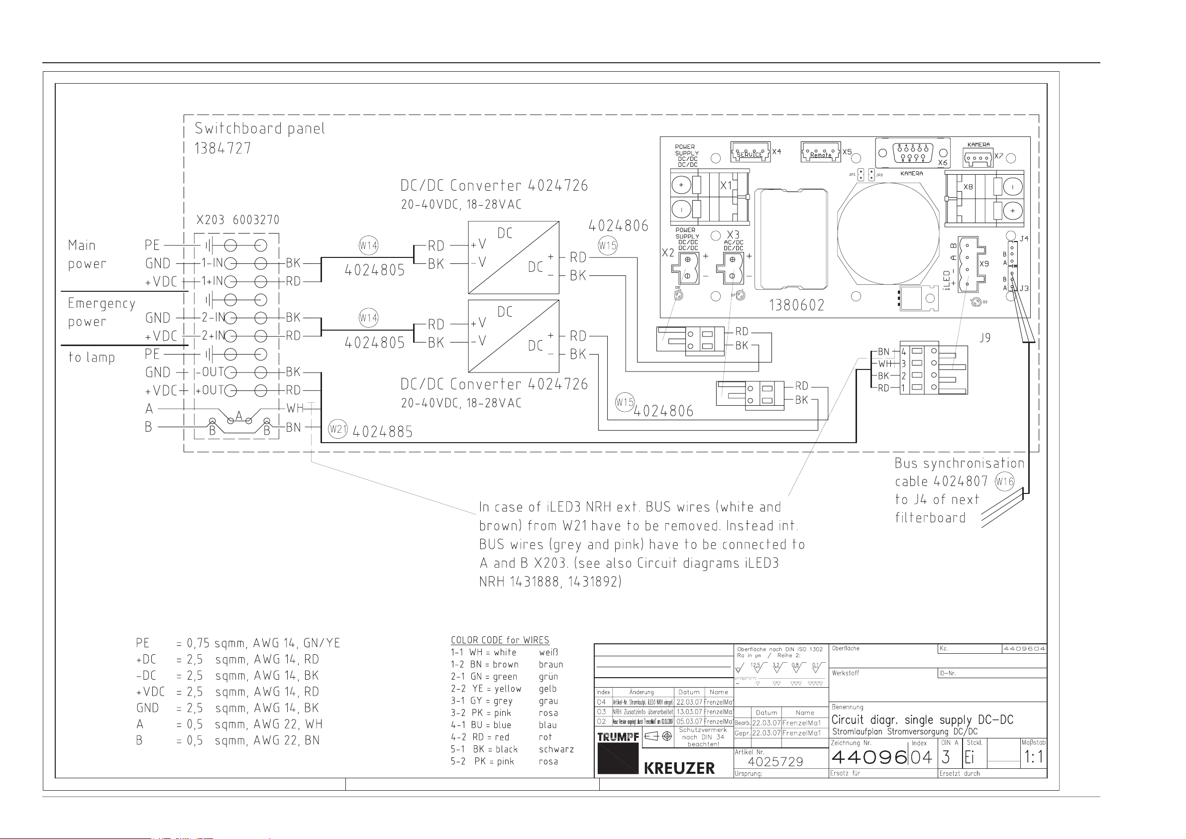
22.2 Circuit Diagram – Control Box Plates
7200681 Installation Instructions iLED US Lighting System – 07/0790
Page 91

22.2 Circuit Diagram – Control Box Plates
917200681 Installation Instructions iLED US Lighting System – 07/07
Page 92

22.2 Circuit Diagram – Control Box Plates
7200681 Installation Instructions iLED US Lighting System – 07/0792
Page 93

22.2 Circuit Diagram – Control Box Plates
937200681 Installation Instructions iLED US Lighting System – 07/07
Page 94

22.3 Circuit Diagram Distance 1-20 m (Maximum Equipment)
7200681 Installation Instructions iLED US Lighting System – 07/0794
Page 95

22.4 Circuit Diagram Distance 21-50 m (Maximum Equipment)
957200681 Installation Instructions iLED US Lighting System – 07/07
Page 96

22.5 Circuit Diagram – iLED 3 LCH
7200681 Installation Instructions iLED US Lighting System – 07/0796
Page 97

22.5 Circuit Diagram – iLED 3 LCH
977200681 Installation Instructions iLED US Lighting System – 07/07
Page 98

22.5 Circuit Diagram – iLED 3 LCH
7200681 Installation Instructions iLED US Lighting System – 07/0798
Page 99

22.5 Circuit Diagram – iLED 3 LCH
997200681 Installation Instructions iLED US Lighting System – 07/07
Page 100

22.6 Circuit Diagram – Camera on Separate Pendant
7200681 Installation Instructions iLED US Lighting System – 07/07100
 Loading...