

Page 1
46 Series
3
21
4
5
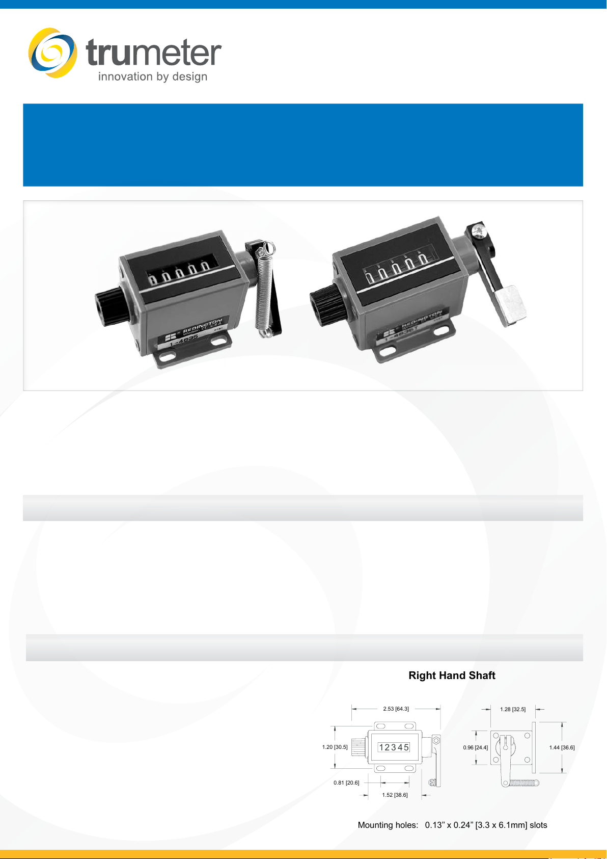
0.81 [20.6]
1.52 [38.6]
2.53 [64.3]
1.20 [30.5]
1.44 [36.6]
1.28 [32.5]
0.96 [24.4]
Right Hand Shaft
Mounting holes: 0.13’’ x 0.24’’ [3.3 x 6.1mm] slots
Mechanical Stroke Counter
These 5 gure stroke counters are especially designed for limited space and high count life
applications. The advanced drive system translates into exceptionally high operating speeds,
extended operating life, for fast and accurate readings. Ideal for copiers, printing presses, cut-o
machines, and piece-part counting applications. Also available with a thumb lever for use as a tally
counter
Key Features
• Compact size
• Reliability
• Low cost
• Optional special levers
• Special Metal Lever
• Lever and spring
• Optional non-reset – consult factory
Specication
Figures 5 gures, white on black, 0.19’’
Reset Standard knob
Speed 1,000 counts/minute
Rotation Top-coming or top-going
Count Stroke 40° Min. - 45° Max.
Shaft Extension Right-hand or left-hand
Shaft Diameter 0.156’’ [4.0mm]
Operating Life Beyond 5 million counts
Temp. Range -15°F to +140°F [-25°C to +60°C]
Weight 2 oz. [57g]
[5mm] high
Applications
• Copiers
• Printing press
• Farm equipment
• Piece-part counting
• Shearing/cut-off machines
Dimensions
Page 2

Mechanical Rotation
Totalizing counters are used to sum the total number of cycles or inputs to a device. These counters have no “outputs”.
Totalizers can be Mechanical, Electromechanical or Electronic.
Totalizers are typically used to total cycle count, piece count, and linear length or to indicate position. Displays for
Mechanical & Electromechanical Totalizers are molded gure wheels usually displaying 0-9 digits on a contrasting
background and have a count capacity of 3-8 gures.
Mechanical Totalizers
The input for Mechanical Totalizers can be Rotary, Stroke or Rotary Ratchet. Mechanical Totalizers require no operating
power or sensor and are easy to install. For hand operated applications you need to consider our Model 46 with thumb
lever option.
Z
Basic operation of a mechanical stroke counter
The illustration (right) shows the lever in the rest position with a total shaft
rotation of X+Y+Z. Although these angles may dier from model to model,
the total shaft rotation contains a pre-travel (X), a count stroke (Y), and
an over-travel (Z). The lever must start in the pre-travel area and continue
through to the over-travel area to register a count. It is recommended that
the spring furnished with the counter be used to simplify adjustment of
count stroke to drive mechanism.
Y
X
SHAFT ROTATIONS:
Arrows indicate shaft rotation to increase count:
Left-hand top-coming:
(rotation #1)
Right-hand top-coming:
(rotation #3)
Part Numbers:
Note: This illustrates rotations 2 and 3 only.
Left-hand top-going:
(rotation #2)
Right-hand top-going:
(rotation #4)
1-4615 Left-hand, top-coming, standard reset knob
1-4625 Left-hand, top-going, standard reset knob
1-4635 Right-hand, top-coming, standard reset knob
1-4645 Right-hand, top-going, standard reset knob
1-4635T Right-hand, top-coming, std. reset knob,
with thumb lever
10007-001 Special Metal Lever
10007-009S Spring and Lever Kit
46-series-DS.v.2.2 04/2017
 Loading...