

Truma Trumatic S 2200, Trumatic S 2200 P Operating Instructions And Installation Instructions
Trumatic S 2200 / S 2200 P
Gebrauchsanweisung Seite 2
Einbauanweisung Seite 5
Im Fahrzeug mitzuführen!
Operating instructions Page 9
Installation instructions Page 11
To be kept in the vehicle!
Mode d‘emploi Page 15
Instructions de montage Page 18
À garder dans le véhicule !
Istruzioni per l‘uso Pagina 22
Istruzioni di montaggio Pagina 25
Da tenere nel veicolo!
Gebruiksaanwijzing Pagina 29
Inbouwhandleiding Pagina 32
Im vertuig meenemen!
Brugsanvisning Side 36
Monteringsanvisning Side 38
Skal medbringes i køretøjet!
Instrucciones de uso Página 42
Instrucciones de montaje Página 45
¡Llévalas en el vehículo!
Page 51
Komfort für unterwegs
Trumatic S 2200 / S 2200 P
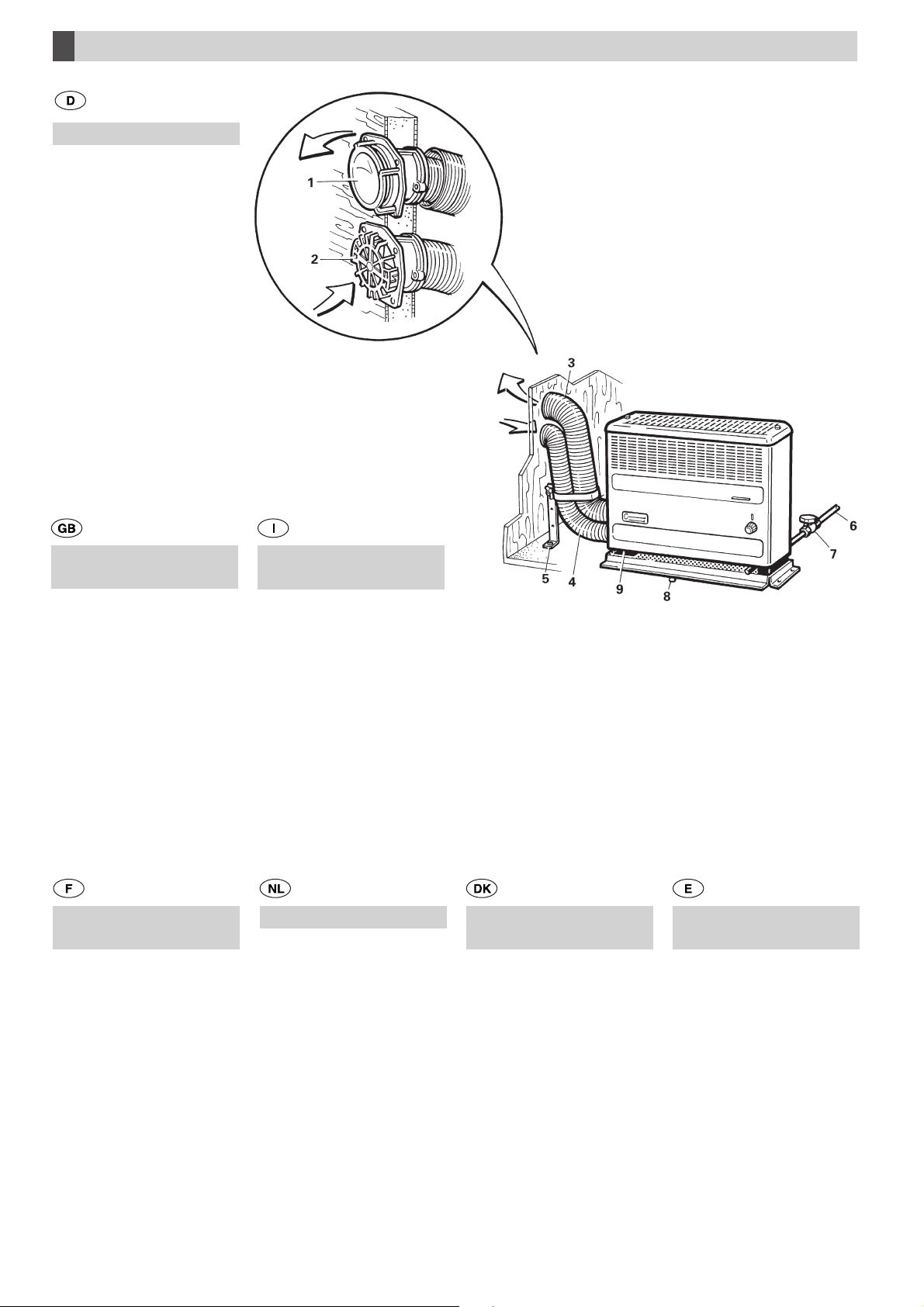
Einbaubeispiel
Dargestellt ist die Heizung
mit Abgas- und Verbrennungsluftführung durch die
Seitenwand
1 Abgaskamin
2 Verbrennungsluftkamin
3 Abgasrohr mit Überrohr
4 Verbrennungsluftrohr
5 Doppelstütze DSW
6 Gaszuleitung
7 Absperrventil
8 Kondenswasserrohr
9 Typenschild
Installation
example
Illustration of the heater with
exhaust and combustion air
routing through the side wall
1 Exhaust cowl
2 Combustion air cowl
3 Exhaust duct with
insulating duct
4 Combustion air duct
5 Double support DSW
6 Gas supply line
7 Shut-off valve
8 Condensation pipe
9 Type plate
Exemple de
montage
Le chauffage est représenté
avec passage des gaz brûlés
et de l’air de combustion par
la parol laterale
Esempio di
montaggio
Raffigurazione del riscaldamento con passagio gas di
scarico e aria combustione
attraverso la parete
1 Camino per gas di scarico
2 Camino per aria
combustione
3 Tubo scarico con tubo
prottetivo
4 Tubo aria di combustione
5 Supporto doppio DSW
6 Tubatura del gas
7 Valvola di chiusura
8 Tubo acqua condensa
9 Targa dati
Inbouwvorbeeld
U ziet de kachel met afvoer
van rookgas en toevoer van
verbrandingslucht via de
wand
Monterings eksempel
Beskrivelsen viser en
ovn med aftræks- og forbrændingsluftrør gennem
sidevæggen
Ejemplo de
montaje
Se representa la calefacción
con conducción de gases de
escape y aire para la combustión a través de la pared lateral.
1 Ventouse d’évacuation des
gaz brûlés
2 Ventouse d’alimentation
en air de combustion
3 Tuyau des gaz brûlés avec
tuyau d’isolation
4 Tuyau d’air de combustion
5 Etai double DSW
6 Conduite d’alimentation
en gaz
7 Robinet de fermeture
8 Tuyau d’évacuation de
l’eau de condensation
9 Plaque signalétique
B
1 Schoorsteen voor
rookgasafvoer
2 Schorsteen voor ver
brandinsluchttoevoer
3 Rookgasafvoerbuis met
beschermingbuis
4 Buis voor verbrandings
luchttoevoer
5 Dubbele steun DSW
6 Gastoevoerleiding
7 Afsluitventiel
8 Afvoerbuis voor
condenswater
9 Typeplaatje
1 Aftræksskorsten
2 Forbrændingsluftskorsten
3 Aftræksrør med overrør
4 Forbrændingsluftrør
5 Dobbelstøtte DSW
6 Gastilførsel
7 Spærreventil
8 Kondensvandrør
9 Typeskilt
1 Chimenea de gases de
escape
2 Chimenea de aire para la
combustión
3 Tubo de gases de escape
con tubo superior
4 Tubo de aire para la
combustión
5 Tubuladura doble DSW
6 Tubería de alimentación
de gas
7 Válvula de bloqueo
8 Tubo de agua de
condensación
9 Placa de características
D1
D2
F
H
H1 H2
E
G
G1
300 mm
300 mm
H3 H4
A
H5
G2
G3
J
J1
J2
K
Trumavent Multivent
C

Trumatic S 2200 / S 2200 P Flüssiggasheizung für Caravans und sonstige Anhänger
Verwendungszweck
Diese Heizung wurde für den Einbau in Caravans und sonstige
Anhänger konstruiert. Der Einbau in Boote ist nicht zulässig.
Andere Anwendungen sind nach Rücksprache mit Truma
möglich.
Gebrauchsanweisung
Vor Inbetriebnahme unbedingt Gebrauchsanweisung
und „Wichtige Bedienungshinweise“ beachten!
Der Fahrzeughalter ist dafür verantwortlich, dass die Bedienung des Gerätes ordnungsgemäß erfolgen kann.
Der dem Gerät beigegebene gelbe Aufkleber mit den Warnhinweisen muss durch den Einbauer bzw. Fahrzeughalter an
einer für jeden Benutzer gut sichtbaren Stelle im Fahrzeug
(z. B. an der Kleiderschranktür) angebracht werden! Fehlende
Aufkleber können bei Truma angefordert werden.
Auf keinen Fall vor Ablauf von 2 Minuten nachzünden, sonst besteht Verpuffungsgefahr! Dies gilt
auch dann, wenn eine bereits in Betrieb befindliche Heizung
verlischt und wieder gezündet werden muss.
5. Heizung ca. 1 Minute in Zündstellung (f) brennen lassen,
dann erst auf „Groß“ (g) stellen.
Falls die Gaszuleitung luftgefüllt ist, kann es bis zu einer Minute dauern, bis Gas zur Verbrennung bereitsteht. Während dieser Zeit ist der Bedienungsknopf gedrückt zu halten und der
Druckzünder dauernd zu betätigen, bis die Flamme brennt.
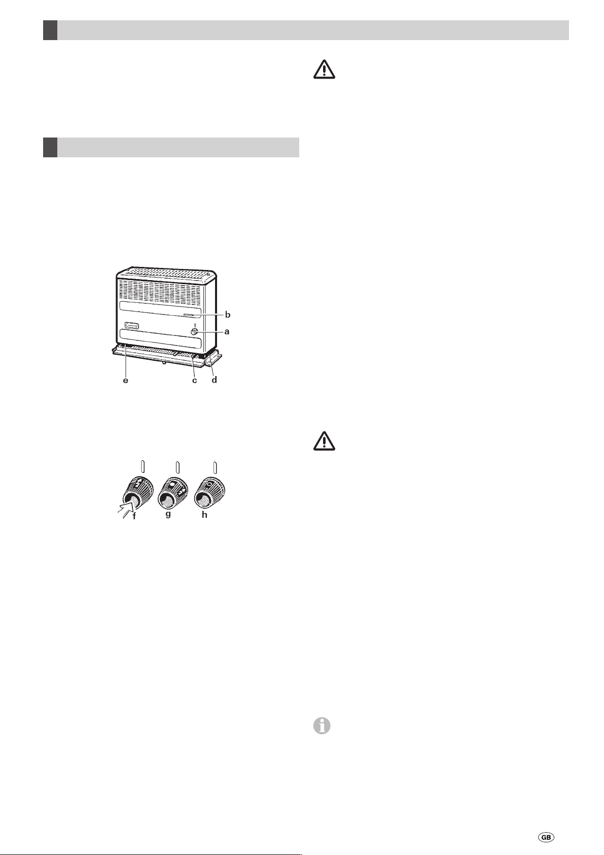
6. Die Heizleistung ist am Bedienungsknopf (a) stufenlos zwischen Kleinstellung (f) und Großstellung (g) einstellbar.
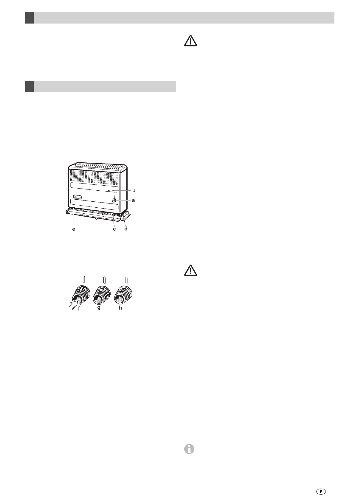
Inbetriebnahme Trumatic S 2200
mit Zündautomat
Vor dem ersten Zünden vergewissern, dass eine Batterie
eingelegt ist (Beschreibung gemäß Punkt „Batteriewechsel
am Zündautomat“)!
1. Kaminkappen abnehmen (bei Wandkamin)!
2. Gasflasche und Schnellschlussventil in der Gaszuleitung
öffnen.
3. Bedienungsknopf (a) auf Funkensymbol (g) stellen und
eindrücken. Zündung erfolgt in dieser Stellung automatisch
(Zündfunke hörbar), bis die Flamme brennt.
a = Bedienungsknopf
b = Sichtfenster zum Beobachten der Flamme
c = Druckzünder (Modell Trumatic S 2200 P)
d = Zündautomat mit Batteriefach (Modell Trumatic S 2200)
e = Typenschild
f = Zünd- und Kleinstellung
g = Großstellung
h = Heizung ausgeschaltet
Bei Geräten mit Abgasanschluss auf der rechten Seite sind die
Teile auf der anderen Seite angeordnet.
Inbetriebnahme Trumatic S 2200 P mit
Druckzünder
1. Kaminkappen abnehmen (bei Wandkamin)!
2. Gasflasche und Schnellschlussventil in der Gaszuleitung
öffnen.
3. Bedienungsknopf (a) auf Funkensymbol (f) stellen und eindrücken. Gleichzeitig Druckzünder (c) solange rasch hintereinander betätigen, bis die Flamme brennt.
Bedienungsgriff bis zu 10 Sekunden gedrückt halten, damit
Zündsicherung anspricht.
Bei Störungen vor erneutem Zündversuch
2 Minuten warten!
4. Sollte die Flamme wieder verlöschen, erfolgt während der
Schließzeit der Zündsicherung (ca. 30 Sekunden) sofortige
Wiederzündung.
5. Heizung ca. 1 Minute in Zündstellung brennen lassen, dann
erst auf „Groß“ (g) stellen.
Falls die Gaszuleitung luftgefüllt ist, kann es bis zu einer
Minute dauern, bis Gas zur Verbrennung bereitsteht. Während
dieser Zeit ist der Bedienungsknopf gedrückt zu halten, bis die
Flamme brennt.
Wenn keine Flamme zustande kommt, arbeitet der Zündautomat weiter, bis am Bedienungsknopf (a) ausgeschaltet wird (h).
6. Die Heizleistung ist am Bedienungsknopf (a) stufenlos zwischen Kleinstellung (f) und Großstellung (g) einstellbar.
Ausschalten
Bedienungsknopf (a) auf „0“ stellen (Zündautomat wird damit gleichzeitig abgeschaltet). Bei längerem Nichtgebrauch
Schnellschlussventil in der Gaszuleitung und Gasflasche
schließen.
Um eine gleichmäßige und rasche Warmluftverteilung
sowie eine Absenkung der Oberflächentemperaturen am
Heizgerät sicherzustellen, empfehlen wir, die Heizung mit
Trumavent Warmluftanlage zu betreiben.
Bedienungsknopf (a) noch bis zu 10 Sekunden gedrückt halten, damit die Zündsicherung anspricht.
4. Weitere 10 Sekunden durch Sichtfenster (b) beo bachten, ob
die Flamme nicht durch Luft in der Leitung (verursacht durch
geschlossenes Ventil oder Flaschenwechsel) verlischt.
2
Wichtige Bedienungshinweise
1. Der Wärmetauscher, das Abgas- und Verbrennungsluftrohr und alle Anschlüsse müssen regelmäßig, in jedem
Fall nach Verpuffungen (Fehlzündungen), von einem Fach-
mann überprüft werden.
6. Für das Heizen während der Fahrt ist in der Richtlinie
2004/78/EG für Motorcaravans eine Sicherheitsabsperreinrichtung vorgeschrieben.
Der Gasdruckregler Truma SecuMotion erfüllt diese
Anforderung.
Das Abgasrohr und das Verbrennungsluftrohr müssen:
– an der Heizung und am Kamin dicht und fest angeschlos-
sen sein,
– aus einem (unverlängerten) Stück bestehen,
– ohne Querschnittsverengungen und unbedingt auf
ganzer Länge steigend verlegt sein,
– zusammen mit dem Überrohr mit mehreren Schellen fest
montiert sein.
Es dürfen keine Gegenstände auf das Abgas- und Verbrennungsluftrohr gelegt werden, da dies zu Beschädigungen
führen könnte.
Heizungen mit falsch montiertem oder beschä-
digtem Abgas- und Verbrennungsluftrohr bzw.
beschädigtem Wärmetauscher dürfen auf keinen Fall
weiter betrieben werden!
2. Der Warmluftaustritt oben an der Heizung darf unter
keinen Umständen behindert werden. Deshalb keinesfalls
Textilien oder Ähnliches zum Trocknen vor oder auf die Heizung hängen. Solche Zweckentfremdung könnte Ihre Heizung
durch die dabei hervorgerufene Überhitzung schwer beschädigen. Keine brennbaren Gegenstände in die Nähe der Heizung
bringen! Bitte beachten Sie dies im Interesse Ihrer Sicherheit.
Achtung: Bauartbedingt wird während des Betriebes
die Heizungsverkleidung heiß. Die Sorgfaltspflicht
gegenüber Dritten (insbesondere Kleinkindern) obliegt dem Betreiber.
Wenn keine Sicherheitsabsperreinrichtung (z. B. der
Gasdruckregler Truma SecuMotion) installiert ist, muss
die Gasflasche während der Fahrt geschlossen sein und es
müssen Hinweis-Schilder jeweils im Flaschenschrank und in
der Nähe des Bedienteiles angebracht werden.
Für das Heizen während der Fahrt in Caravans empfehlen wir
zur Sicherheit ebenfalls die Sicherheitsabsperreinrichtung.
Wartung
Bei einer Störung wenden Sie sich bitte grundsätzlich an den
Truma Service (siehe Truma Serviceheft oder www.truma.com).
Achtung: Trotz sorgfältiger Fertigung kann die Heizung scharfkantige Teile enthalten, deshalb bei Wartungs- und Reinigungsarbeiten immer Schutzhandschuhe verwenden!
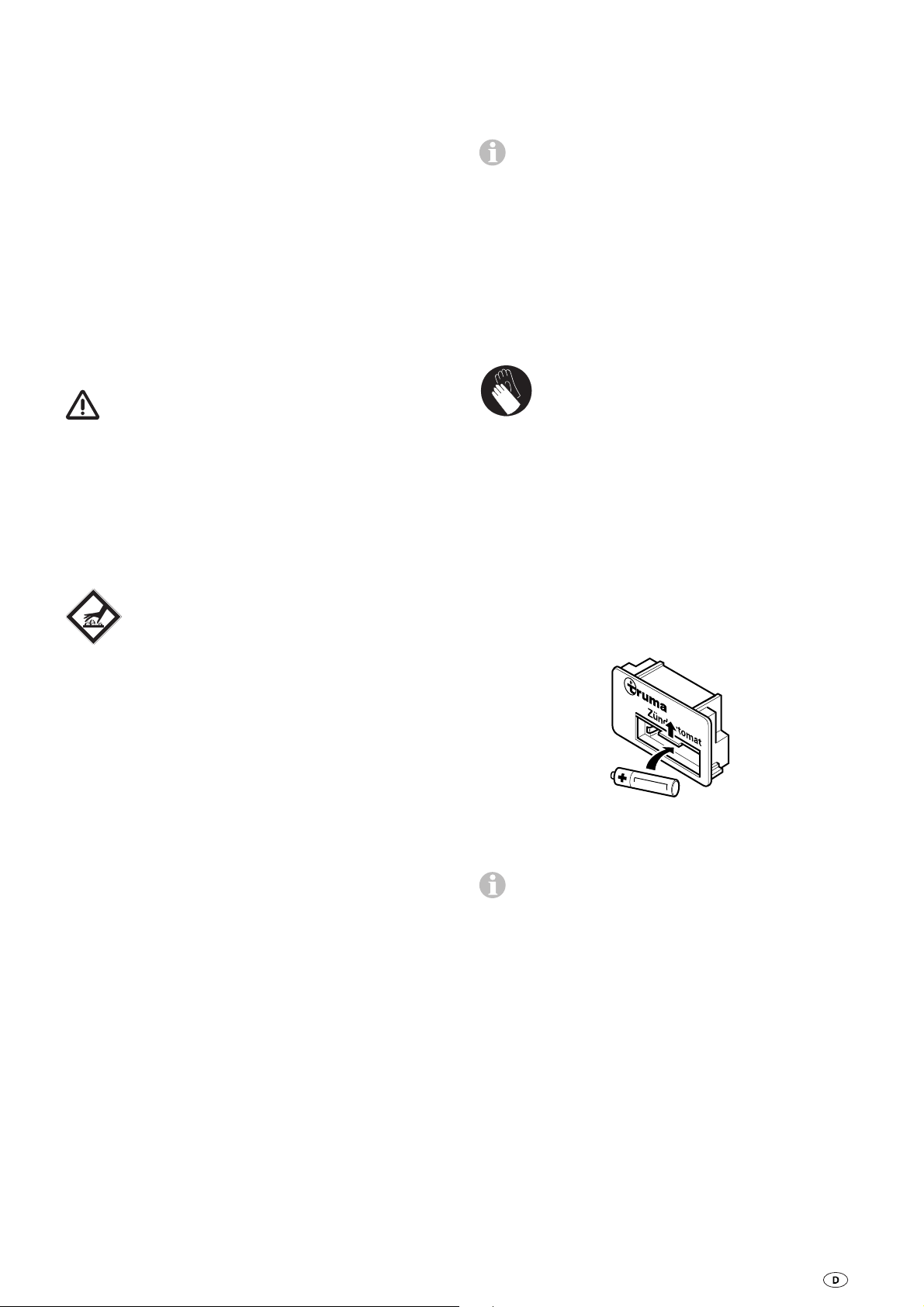
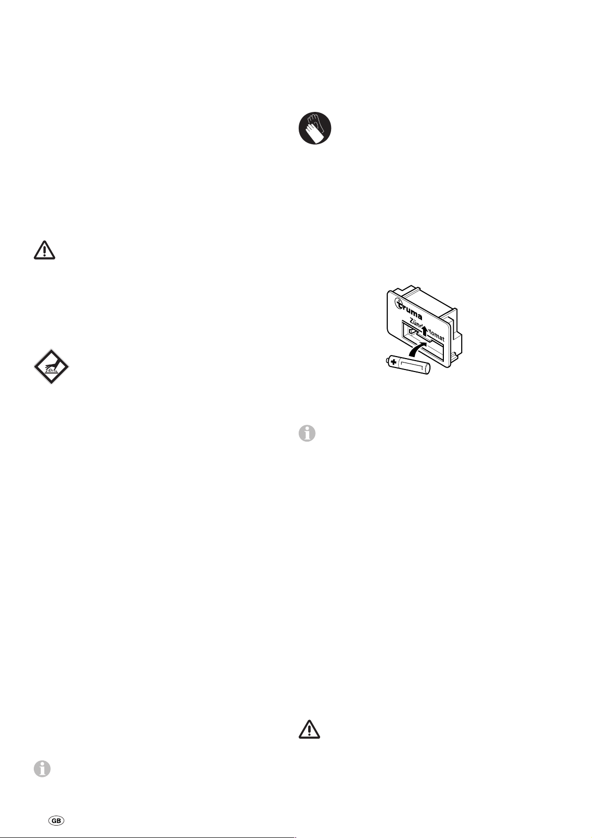
Batteriewechsel am Zündautomat
Sind keine Zündfunken hörbar oder nur in Zeitabständen von
mehr als einer Sekunde, muss die Batterie erneuert werden.
Batterie nur bei ausgeschalteter Heizung wechseln. Vor Beginn jeder Heizsaison neue Batterie einsetzen! Alte Batterie
fachgerecht entsorgen!
Batteriefachabdeckung nach oben schieben und Batterie
wechseln. Plus / Minus beachten. Batteriefach wieder
schließen.
3. Bei Abgas- und Verbrennungsluftführung durch die
Seitenwand muss auf folgendes geachtet werden:
Die Kamine müssen in der vorgeschriebenen Höhe verlegt
sein (siehe Einbauanweisung). Bei Rohrlängen ab 35 cm muss
eine Doppelstütze DSW montiert sein.
Die Abdeckkappen für die Kamine (Zubehör) sind stets aufzusetzen, wenn die Heizung nicht in Betrieb ist.
4. Bei Abgasführung über Dach muss auf folgendes
geachtet werden:
Falls am Wohnwagen ein Überdach montiert wird, muss der
Abgaskamin unbedingt durch dieses Dach hindurchgeführt
werden. Verwenden Sie dafür die Kamindurchführung UEK
(Art.-Nr. 30630-04)!
Sollte die Heizung bei Stand orten mit extremen Windverhältnissen wiederholt verlöschen, empfehlen wir die Verwendung
einer Kaminverlängerung AKV (Art.-Nr. 30010-20800). Diese
muss während der Fahrt abgenommen werden, um nicht verloren zu gehen (Unfallgefahr).
Für Winter- bzw. Dauercamping empfehlen wir den auf das
Kaminteil aufschraubbaren Kaminverlängerungssatz SKV
(Art.-Nr. 30690-00). Dieser muss während der Fahrt abgenommen werden, um nicht verloren zu gehen (Unfallgefahr).
5. Die Verbrennungsluft-Ansaugung unter dem Fahrzeugboden muss von Schmutz und Schneematsch freigehalten
werden. Der Ansaugstutzen der Heizung darf deshalb nicht im
Spritzbereich der Räder liegen, evtl. Spritzschutz anbringen.
Nur temperaturbeständige (+70° C), auslaufsichere MignonBatterie (LR 6, AA, AM 3) verwenden (Art.-Nr. 30030-99200),
andere Batterien können Funktionsstörungen verursachen!
Vor dem Verschrotten des Zündautomaten unbedingt die
Batterie entfernen und fachgerecht entsorgen!
Reinigung (nur bei ausgeschaltetem Gerät!)
Es empfiehlt sich, mindes tens einmal jährlich vor Beginn der
Heizsaison den sich am Wärmetauscher, an der Bodenplatte
und am Lüfterrad der Trumavent Warmluftanlage ansammelnden Staub zu entfernen. Das Lüfterrad muss vorsichtig mit
einem Pinsel oder einer Zahnbürste gereinigt werden.
3

Allgemeine Sicherheitshinweise
Für den Betrieb von Gasreglern, Gasgeräten bzw. Gasanlagen,
ist die Verwendung von stehenden Gasflaschen aus denen
Gas aus der Gasphase entnommen wird zwingend vorgeschrieben. Gasflaschen aus denen Gas aus der Flüssigphase
entnommen wird (z. B. für Stapler) sind für den Betrieb verboten, da sie zur Beschädigung der Gasanlage führen.
Bei Undichtigkeiten der Gasanlage bzw. bei Gasgeruch:
– alle offenen Flammen löschen
– Fenster und Türe öffnen
– alle Schnellschlussventile und Gasflaschen schließen
– nicht rauchen
– keine elektrischen Schalter betätigen
– die gesamte Anlage von einem Fachmann überprüfen
lassen!
Reparaturen dürfen nur vom Fachmann durchgeführt
werden.
Nach jeder Demontage der Abgasführung muss ein neuer
O-Ring montiert werden!
Zum Erlöschen von Gewährleistungs- und Garantieansprüchen sowie zum Ausschluss von Haftungsansprüchen führen
insbesondere:
– Veränderungen am Gerät (einschließlich Zubehörteilen),
– Veränderungen an der Abgasführung und am Kamin,
– Verwendung von anderen als Truma Originalteilen als
Ersatz- und Zubehörteile,
– das Nichteinhalten der Einbau- und Gebrauchsanweisung.
Außerdem erlischt die Betriebserlaubnis des Gerätes und
dadurch in manchen Ländern auch die Betriebserlaubnis des
Fahrzeuges.
Für Fahrzeuge empfehlen wir den Truma Gasdruckregler
SecuMotion bzw. für die Zweiflaschen-Gasanlage das automatische Umschaltventil Truma DuoComfort.
Bei Temperaturen um 0° C und darunter sollten der Gasdruckregler bzw. das Umschaltventil mit der Reglerbeheizung EisEx
betrieben werden.
Es dürfen nur für das Bestimmungsland geeignete ReglerAnschlussschläuche, die den Anforderungen des Landes
entsprechen, verwendet werden. Diese sind regelmäßig auf
Brüchigkeit zu überprüfen. Für den Winterbetrieb sollten nur
winterfeste Spezialschläuche verwendet werden.
Druckregelgeräte und Schlauchleitungen müssen spätestens
10 Jahre (bei gewerblicher Nutzung 8 Jahre) nach Herstellungsdatum gegen neue ausgewechselt werden. Der Betreiber ist dafür verantwortlich.
Technische Daten
ermittelt nach EN 624 bzw. Truma Prüfbedingungen
Gasart
Flüssiggas (Propan / Butan)
Betriebsdruck
30 mbar (siehe Typenschild)
Nennwärmeleistung
1850 W
Gasverbrauch
50 – 170 g/h
Der Betriebsdruck der Gasversorgung 30 mbar muss
mit dem Betriebsdruck des Gerätes (siehe Typenschild)
über einstimmen.
Die Flüssiggasanlagen müssen den technischen und administrativen Bestimmungen des jeweiligen Verwendungslandes
entsprechen (z. B. EN 1949 für Fahrzeuge). Nationale Vorschriften und Regelungen (in Deutschland z. B. das DVGW-Arbeitsblatt G 607) müssen beachtet werden.
Die Prüfung der Gasanlage muss alle 2 Jahre von einem
Fachmann wiederholt werden und gegebenenfalls in der Prüfbescheinigung (in Deutschland z. B. gemäß DVGW-Arbeitsblatt G 607) bestätigt werden.
Verantwortlich für die Veranlassung der Überprüfung ist
der Fahrzeughalter.
Flüssiggasgeräte dürfen beim Tanken, in Parkhäusern, Garagen oder auf Fähren nicht benutzt werden.
Bei erster Inbetriebnahme eines fabrikneuen Gerätes (bzw.
nach längerer Stillstandszeit) kann kurzzeitig eine leichte
Rauch- und Geruchsentwicklung auftreten. Es ist zweckmäßig, das Gerät dann sofort mit höchster Leis tung brennen zu
lassen und für gute Durchlüftung des Raumes zu sorgen.
Ein ungewohntes Brennergeräusch oder Abheben der Flamme
lässt auf einen Reglerdefekt schließen und macht eine Überprüfung des Reglers notwendig.
Wärmeempfindliche Ge genstände (z. B. Spray dosen) oder
brennbare Flüssigkeiten dürfen nicht im Ein bauraum der
Heizung verstaut werden, da es hier un ter Umständen zu
erhöhten Temperaturen kommen kann.
Für die Gasanlage dürfen nur Druckregeleinrichtungen gemäß EN 12864 (in Fahrzeugen) mit einem festen Ausgangsdruck von 30 mbar verwendet werden. Die Durchflussrate
der Druckregeleinrichtung muss mindestens dem Höchstverbrauch aller vom Anlagenhersteller eingebauten Geräte
entsprechen.
4
Einbauanweisung
Die Verbrennungsluft darf nicht aus dem Fahrzeuginnenraum entnommen werden. Es muss immer die Verbrennungsluft von außen zugeführt werden.
!"Bitte Bilderseite ausklappen!
Einbau und Reparatur der Heizung darf nur vom Fachmann durchgeführt werden. Vor Beginn der Arbeiten
Einbauanweisung sorgfältig durchlesen und befolgen!
Bei Nichteinhaltung der Einbauvorschriften bzw.
unsachgemäßem Einbau besteht Lebensgefahr!
Zulassung
Für das Heizen während der Fahrt ist in der Richtlinie
2004/78/EG für Motorcaravans eine Sicherheitsabsperreinrichtung vorgeschrieben. Für das Heizen während der
Fahrt in Caravans empfehlen wir zur Sicherheit ebenfalls die
Sicherheitsabsperreinrichtung.
Der Gasdruckregler Truma SecuMotion erfüllt diese Anforderung.
Durch den Einbau des Reglers mit entsprechend ausgelegter
Gasinstallation ist der Betrieb einer typgeprüften Flüssiggasheizung während der Fahrt gemäß der EU-Richtlinie
2001/56/EG europaweit zulässig.
Der Einbau in Motorcaravans (Fahrzeugklasse M1),
Kraftomnibusse (Fahrzeugklasse M2 und M3), Nutzfahrzeuge (Fahrzeugklasse N) sowie in Fahrzeuge zum Transport von gefährlichen Gütern ist nicht zulässig.
Bei Einbau in Sonderfahrzeuge müssen die dafür geltenden
Vorschriften berücksichtigt werden.
Konformitätserklärung
Die Trumatic S 2200 (P) ist durch den DVGW geprüft und
erfüllt die Gasgeräte-Richtlinie (90/396/EWG) sowie die mitgeltenden EG-Richtlinien. Für EU-Länder liegt die CE-ProduktIdent-Nummer vor: CE-0085AP0324.
Die Heizung erfüllt die Heizgeräte-Richtlinie 2001/56/EG mit
den Ergänzungen 2004/78/EG und 2006/119/EG und trägt die
Typengenehmigungsnummer: e1 00 0139
Die Heizung erfüllt die Richtlinie zur Funkentstörung von
Kraftfahrzeugmotoren 72/245/EWG mit den Ergänzungen
2004/104/EG, 2005/83/EG und 2006/28/EG und trägt die
Typgenehmigungsnummer: e1 03 2603
Die Heizung erfüllt die EMV-Richtlinie 89/336/EWG.
Platzwahl
1. Das Gerät und seine Abgasführung ist grundsätzlich so einzubauen, dass es für Servicearbeiten jederzeit gut zugänglich
ist und leicht aus- und eingebaut werden kann.
2. Die Heizung kann im Kleiderschrank mit Einbaukasten
(Bild D1) oder frei im Raum – ggf. mit Rückwand (Bild D2) –
eingebaut werden. Bei der Platzwahl ist darauf zu achten, dass
die Bohrungen gemäß Bodenschablone durchgeführt werden
können. Serienmäßig befindet sich der Abgasrohr-Anschluss
auf der linken Seite (Bedienungsknopf rechts).
Auf Wunsch ist das Gerät auch mit Abgasrohr-Anschluss auf
der rechten Seite lieferbar.
3. Abgasleitungen und Kamine müssen so installiert
sein, dass das Eindringen von Abgasen in das Fahrzeuginnere nicht möglich ist. Das Ansaugrohr für die Verbrennungsluft (bei Abgasführung über Dach) darf nicht
im Spritzbereich der Räder liegen, evtl. Spritzschutz
anbringen.
Abgas- und Verbrennungsluftführung durch
die Seitenwand
Bild E
Der Kamin ist so anzubringen, dass sich innerhalb von
500 mm (A) kein Tankstutzen oder Tankentlüftungsöffnung
befindet. Außerdem bei der Platzwahl beachten, dass sich
direkt oberhalb und 300 mm seitlich keine zu öffnenden Fenster, Luken oder Entlüftungsöffnungen für den Wohnbereich
befinden.
Für die Betriebssicherheit ist es unbedingt erforderlich,
dass die Kamine für Abgas- und Verbrennungsluft in
der vorgeschriebenen Höhe platziert werden. Diese Höhe
(Abstand zwischen Heizungssockel und Mitte der Abgaskaminbohrung) richtet sich jeweils nach den verwendeten
Rohrlängen.
Um eine gleichmäßige und rasche Warmluftverteilung
sowie eine Absenkung der Oberflächentemperaturen am
Heizgerät sicherzustellen, empfehlen wir den Einbau einer
Trumavent Warmluftanlage.
Vorschriften
Jede Veränderung am Gerät (einschließlich Abgasführung und
Kamin) oder die Verwendung von Ersatzteilen und funktionswichtigen Zubehörteilen, die keine Truma Originalteile sind,
sowie das Nichteinhalten der Einbau- und Gebrauchsanweisung
führt zum Erlöschen der Garantie sowie zum Ausschluss von
Haftungsansprüchen. Außerdem erlischt die Betriebserlaubnis
des Gerätes und dadurch in manchen Ländern auch die Betriebserlaubnis des Fahrzeuges.
Das Jahr der ersten Inbetriebnahme muss auf dem
Typenschild angekreuzt werden.
Der Einbau des Gerätes muss den technischen und administrativen Bestimmungen des jeweiligen Verwendungslandes
entsprechen (z. B. EN 1949). Nationale Vorschriften und Regelungen (in Deutschland z. B. das DVGW-Arbeitsblatt G 607)
müssen beachtet werden.
In anderen Ländern sind die jeweils gültigen Vorschriften zu
beachten.
Nähere Angaben zu den Vorschriften in den entsprechenden
Bestimmungsländern können über unsere Auslands-Vertretungen (siehe Truma Serviceheft oder www.truma.com)
angefordert werden.
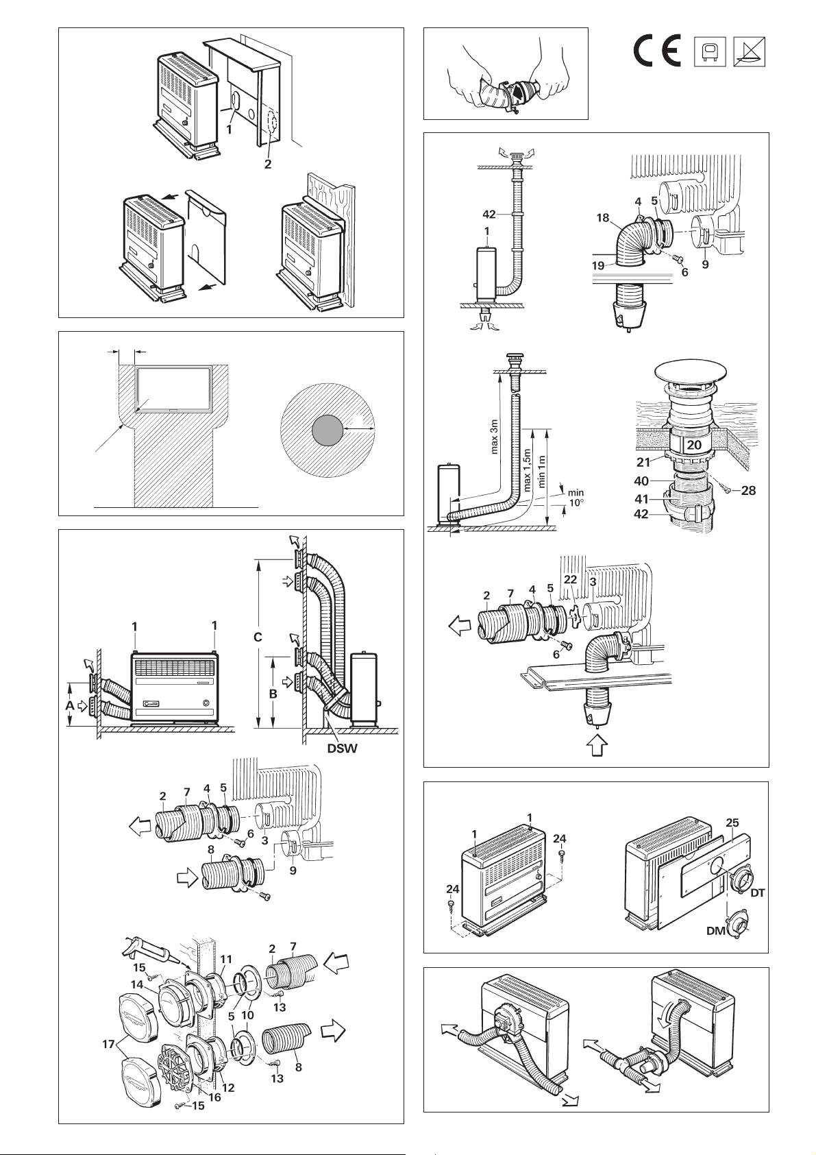
Heizungseinbau
– Einbau im Kleiderschrank mit Einbaukasten EKM
1. Schrankvorderteil 440 mm hoch und 480 mm breit ausschneiden. Einbaukasten behelfsmäßig in den Schrankausschnitt einsetzen.
2. Bodenschablone in den Einbaukasten so einlegen, dass sie
genau hinten in den Ecken anliegt (L = Abgasrohranschluss
links, R = Abgasrohranschluss rechts) und mit Reißnägeln befestigen. Einbaukasten herausnehmen.
3. Gemäß Schablone Boden öffnung Ø 15 mm für Kondenswasserablauf bohren und die 4 Punkte für die Befestigungsschrauben vorstechen.
4. Nur bei Abgasführung über Dach: Loch Ø 65 mm für
Verbrennungsluft-Ansaugrohr bohren.
Die Maße müssen genau eingehalten werden!
5. Einbaukasten wieder einsetzen und anschrauben. Vorgestanzte Öffnung für die Durchführung der Abgasführung
links (1) oder rechts (2) ausbrechen (siehe Bild D1).
5
– Einbau frei im Raum
1. Bodenschablone auf den gewählten Platz legen.
2. Gemäß Schablone Boden öffnung Ø 15 mm für Kondenswasserablauf bohren und die 4 Punkte für die Befestigungsschrauben vorstechen.
3. Nur bei Abgasführung über Dach: Loch Ø 65 mm für
das Verbrennungsluft-Ansaugrohr bohren.
Die Maße müssen genau eingehalten werden!
Sollte bei freistehenden Heizungen die unverkleidete Rückseite zu sehen sein oder sollten sich Holzteile im Strahlungsbereich der Heizung befinden, empfiehlt sich der Einbau einer
Rückwand (Bild D2).
Rohranschluss an die Heizung
1. Bild G1
Die beiden Schrauben (1) oben an der Heizung lösen und Verkleidung abnehmen.
2. Bild G2
Abgasrohr (2) am oberen Heizungsstutzen (3) wie folgt anschließen: Dichtplatte (4) etwa 3 cm auf das Rohr schieben
(Kralle zeigt zur Heizung), O-Ring (5) durch Ausweiten vorsichtig über die Rohrschnittkante führen und Rohr bis auf
Anschlag in den Heizungsstutzen (3) stecken. Dichtplatte
zusammen mit O-Ring ganz heranschieben und durch Drehen
einhängen. Mit Schraube (6) fest anziehen.
Nach jeder Demontage muss ein neuer O-Ring (5) montiert werden!
Abgas- und Verbrennungsluft führung
durch die Seitenwand
Für die Trumatic S 2200 darf nur das Truma EdelstahlAbgasrohr AE 3 (Art.-Nr. 30140-00) mit Truma Überrohr ÜR
(APP – Art.-Nr. 40230-00) verwendet werden, da das Heizgerät
nur in Verbindung mit diesen Rohren geprüft und zugelassen
ist.
Bild F
Eine erhebliche Montage-Erleichterung für das Biegen des
Edelstahlrohres und das Aufziehen des O-Ringes bringt die
Verwendung des Biege-Boys (Art.-Nr. 30030-33000).
(Kamin-Set AKW)
Kaminbohrung AKW
Die Wandkamine an einer möglichst geraden Fläche montieren,
die allseitig vom Wind umströmt werden kann.
Gemäß der nachstehenden Einbauvarianten (A, B oder C) die
beiden Kaminöffnungen Ø 79 mm bohren (bei Hohlräumen
im Bereich der Kaminbohrung mit Holz ausfüttern) und die
Löcher für die Wandschrauben vorstechen.
Die vorgeschriebene Mindesthöhe (= Abstand zwischen
Heizungssockel und Mitte der Abgaskaminbohrung) genau
einhalten!
Bild G1
Einbauvariante A:
Bei Rohrlängen bis 35 cm (die Rohre müssen seitlich durch
die Heizungsverkleidung geführt werden) muss der Abgaskamin in einer Mindesthöhe von 20 cm montiert werden. Dazu Wandschablone an der gestrichelten Linie falzen, Falz am
Boden aufliegen lassen.
3. Überrohr (7) auf das Abgasrohr schieben (muss vom Kamin
bis zur Heizung reichen).
4. Verbrennungsluftrohr (8) am unteren Heizungsstutzen (9)
in gleicher Weise anschließen.
Abgasrohr mit Überrohr und Verbrennungsluftrohr
müssen auf ganzer Länge steigend verlegt sein
und gemäß Bild G1 gegen jegliche Veränderung mit Doppelstütze DSW (Einbauvarianten B + C) gesichert werden. Sonst
kann sich ein Wassersack bilden, welcher den freien
Abzug der Abgase verhindert!
Rohranschluss an die Kamine
Bild G3
Heizung auf den vorgesehenen Platz stellen, Rohre zu den
Kaminbohrungen führen und notwendige Rohrlängen festlegen, ggf. kürzen. Heizung so zur Wand schieben, dass Rohre
ca. 4 cm aus der Wand herausragen.
Das Abgasrohr (2) mit Überrohr (7) befindet sich ober-
halb des Verbrennungsluft-Zuführungsrohres (8)!
Dichtscheiben (10) etwa 3 cm auf die Rohre schieben.
O-Ringe (5) durch Ausweiten über die Rohrschnittkanten
führen und Rohre (2) und (8) bis auf Anschlag in die Kamine
(11 + 12) stecken (Kamin-Anschlussstutzen müssen nach unten zeigen). Dichtscheiben zusammen mit den O-Ringen ganz
heranschieben und mit je 2 Schrauben (13) sicher befestigen.
Nach jeder Demontage muss ein neuer O-Ring (5) montiert werden!
Befestigung der Kamine
Einbauvariante B:
Bei Rohrlängen bis 75 cm muss der Abgaskamin in einer
Mindesthöhe von 33 cm montiert werden. Dazu Wand-
schablone am Boden aufliegen lassen.
Einbauvariante C:
Bei Rohrlängen bis 120 cm muss der Abgaskamin in einer
Mindesthöhe von 66 cm montiert werden (zwischen Hei-
zungssockel und Mitte Abgaskaminbohrung ausmessen).
Die Rohre können gekürzt werden, der Mindestabstand zwischen den Kaminen (11,5 cm) darf jedoch nicht unterschritten werden. Im Bedarfsfall können die Kamine bis zu einem
Abstand von max. 22 cm montiert werden. Bei den Einbauvarianten B und C können die Rohre seitlich durch die Heizungsverkleidung oder nach hinten abgewinkelt werden und
es muss die Doppelstütze DSW montiert werden. Falls
erforderlich, kann die Stütze durch Abschneiden oder Abbiegen gekürzt werden.
6
Bild G3
Abgaskamin (11) an der Dichtfläche mit plastischem Karosseriedichtmittel (kein Silikon!) bestreichen und in die obere
Kaminbohrung schieben (Kamin-Anschlussstutzen muss nach
unten zeigen). Abgaskamin (11) und Kaminscheibe (14) mit
4 Schrauben (15) befestigen.
Verbrennungsluftkamin (12) in der unteren Kaminbohrung
in gleicher Weise zusammen mit dem Ansauggitter (16)
befestigen.
Abdeckkappen (17) für die Kamine stets aufsetzen, wenn die
Heizung nicht in Betrieb ist (Zubehör).
Abgasführung über Dach (Kamin-Set AKD)
Für die Trumatic S 2200 darf nur das Truma EdelstahlAbgasrohr AE 3 (Art.-Nr. 30140-00) mit Truma Überrohr ÜR
(APP – Art.-Nr. 40230-00) verwendet werden, da das Heizgerät
nur in Verbindung mit diesen Rohren geprüft und zugelassen
ist. Gesamtlänge des Abgasrohres max. 3 m!

Bild F
Eine erhebliche Montage-Erleichterung für das Biegen des
Edelstahlrohres und das Aufziehen des O-Ringes bringt die
Verwendung des Biege-Boys (Art.-Nr. 30030-33000).
Abgasrohr (40) mit Überrohr (41) muss auf ganzer
Länge steigend und mit mehreren Schellen (42) fest
und dauerhaft montiert sein, da sich sonst ein Wassersack bilden kann, welcher den freien Abzug der Abgase
verhindert.
Montage der Verbrennungsluft-Ansaugung
1. Bild H1
Die beiden Schrauben (1) oben an der Heizung lösen und Verkleidung abnehmen.
2. Bild H2
Vor dem Einbau der Heizung Rohrkrümmer für die Verbrennungsluft-Ansaugung am unteren Heizungsstutzen wie folgt
montieren: Rohrkrümmer (18) mit der Rohrschnittkante von
unten durch die Bohrung (19) im Heizungssockel schieben.
Dichtplatte (4) etwa 3 cm auf das Rohr schieben (Kralle zeigt
zum Heizungsstutzen). O-Ring (5) durch Ausweiten vorsichtig
über die Rohrschnittkante führen und Rohrkrümmer bis auf
Anschlag in den unteren Heizungsstutzen (9) stecken. Dichtplatte zusammen mit O-Ring ganz heranschieben und durch
Drehen einhängen. Mit Schraube (6) fest anziehen.
Nach jeder Demontage muss ein neuer O-Ring (5) montiert werden!
3. Heizung in die Bodenöffnung stellen.
Montage des Dachkamins
Der Dachkamin darf nur senkrecht oder mit maximal 15 Grad
Neigung eingebaut werden!
Bild H3
Dachkamin so platzieren, dass von der Heizung zum Kamin
eine direkte, auf ganzer Länge steigende Rohrverlegung (max.
3 m!) möglich ist. Bei 1,5 m Rohrlänge muss mindestens 1 m
Höhe erreicht sein.
Befestigung der Heizung
Bild J1
Heizung mit den 4 mitgelieferten Blechschrauben (24) durch
den Heizungssockel am Fahrzeugboden befestigen. Heizungsverkleidung – ggf. mit Rückwand – montieren (Durchbrüche
für Rohre an der Verkleidung oder Rückwand ausbrechen).
Schrauben (1) anziehen.
Bild J2
Das Wärmeleitblech (25) ist einzusetzen, wenn die Wärmestrahlung nach vorne geführt werden soll oder wenn ein Gebläse zur Warmluftverteilung angeschlossen wird.
Warmluftverteilung
Bild K
Für die Warmluftverteilung sind alle Truma Gebläse geeignet
(Trumavent oder Mulitvent). Das Gebläse kann am Boden oder
an der Wand des Fahrzeuges in Heizungsnähe angebracht
werden.
Bild J2
Die Verbindung zur Heizung erfolgt mittels Ansaugdüse DT
(Art.-Nr. 40660-00) bei Trumavent (für Rohr Ø 85 mm) oder
Ansaugdüse DM (Art.-Nr. 40670-00) bei Multivent (für Rohr
Ø 65 mm).
Für den Anschluss ist der Einbaukasten EKM oder die Rückwand RWS bzw. RWSL mit Wärmeleitblech erforderlich. Die
Trumavent Gebläse können auch direkt am Einbaukasten befestigt werden.
1. Bild H4
Öffnung von Ø 60 mm in einem Mittelabstand von mind.
55 mm zu seitlichen Wänden ausschneiden. Bei doppelschaligen Dächern den Hohlraum mit Holz ausfüttern oder einen
kreisförmig eingerollten Blechstreifen (20) von etwa 220 mm
Länge und 1 mm Stärke einschieben, um das Dach so zu
versteifen, dass es beim Anziehen der Verschraubung nicht
verformt wird und regendicht bleibt.
2. Kamin von oben durch das Dach stecken und innen mit
Schraubring (21) festziehen.
Abdichtung erfolgt mit beigelegter Gummidichtung ohne
weitere Dichtmittel.
Montage des Abgasrohres
1. Bild H5
Drosselblech (22) in den oberen Heizungsstutzen (3) bis zum
Anschlag einschieben.
2. Abgasrohr (2) am oberen Heizungsstutzen (3) wie folgt
anschließen: Dichtplatte (4) etwa 3 cm auf das Abgasrohr
schieben (Kralle zeigt zum Heizungsstutzen). O-Ring (5) durch
Ausweiten vorsichtig über die Rohrschnittkante führen und
Abgasrohr bis auf Anschlag in den oberen Heizungsstutzen
stecken. Dichtplatte zusammen mit O-Ring heranschieben
und durch Drehen einhängen. Mit Schraube (6) fest anziehen.
Nach jeder Demontage muss ein neuer O-Ring (5) montiert werden!
3. Überrohr (7) auf das Abgasrohr schieben (muss vom Kamin
bis zur Heizung reichen).
Zum weiteren Ausbau der Warmluftanlage werden die Einzelteile des Trumavent Systems verwendet.
Gasanschluss
Der Betriebsdruck der Gasversorgung 30 mbar muss
mit dem Betriebsdruck des Gerätes (siehe Typenschild)
übereinstimmen.
Das Gaszuleitungsrohr Ø 8 mm muss mit einer Schneidringverschraubung am Anschlussstutzen angeschlossen werden.
Beim Festziehen sorgfältig mit einem zweiten Schlüssel
gegenhalten!
Der Gasanschlussstutzen am Gerät darf nicht gekürzt oder
verbogen werden.
Vor dem Anschluss an das Gerät sicherstellen, dass die Gasleitungen frei von Schmutz, Spänen u. Ä. sind!
Die Rohrverlegung ist so zu wählen, dass für Servicearbeiten
das Gerät wieder ausgebaut werden kann.
In der Gaszuleitung ist die Anzahl der Trennstellen in von Personen benutzten Räumen auf die technisch unvermeidbare
Anzahl zu begrenzen.
Die Gasanlage muss den technischen und administrativen Bestimmungen des jeweiligen Verwendungslandes entsprechen
(in Europa z. B. EN 1949 für Fahrzeuge).
Nationale Vorschriften und Regelungen (in Deutschland z. B.
das DVGW-Arbeitsblatt G 607 für Fahrzeuge) müssen beachtet werden.
4. Bild H4
Rohre an der Wand mit wenig Krümmungen hochführen. Abgasrohr (40) in den Kamin bis Anschlag einschieben und mit
Blechschraube (28) sichern.
7

Funktionsprüfung
Truma Hersteller Garantieerklärung
Nach dem Einbau muss die Dichtigkeit der Gaszuleitung
nach der Druckabfallmethode geprüft werden. Eine Prüf-
bescheinigung (in Deutschland z. B. gemäß DVGW-Arbeitsblatt G 607) ist auszustellen.
Anschließend gemäß der Gebrauchsanweisung sämtliche
Funktionen des Gerätes prüfen.
Die Gebrauchsanweisung mit ausgefüllter Garantiekarte ist
dem Fahrzeughalter auszuhändigen.
Warnhinweise
Der dem Gerät beigegebene gelbe Aufkleber mit den Warnhinweisen muss durch den Einbauer bzw. Fahrzeughalter an
einer für jeden Benutzer gut sichtbaren Stelle im Fahrzeug
(z. B. an der Kleiderschranktür) angebracht werden! Fehlende
Aufkleber können bei Truma angefordert werden.
1. Garantiefall
Der Hersteller gewährt Garantie für Mängel des Gerätes, die
auf Material- oder Fertigungsfehler zurückzuführen sind. Daneben bestehen die gesetzlichen Gewähr leistungsansprüche
gegen den Verkäufer fort.
Der Garantieanspruch besteht nicht:
– für Verschleißteile und bei natürlicher Abnutzung,
– infolge Verwendung von anderen als Truma Originaltei-
len in den Geräten und bei Verwendung ungeeigneter
Gasdruckregler,
– infolge Nichteinhaltung der Truma Einbau- und
Gebrauchs anweisungen,
– infolge unsachgemäßer Behandlung,
– infolge unsachgemäßer, nicht von Truma veranlass ter
Transportverpackung.
2. Umfang der Garantie
Die Garantie gilt für Mängel im Sinne von Ziffer 1, die innerhalb von 24 Monaten seit Abschluss des Kaufvertrages zwischen dem Verkäufer und dem Endverbraucher eintreten. Der
Hersteller wird solche Mängel durch Nacherfüllung beseitigen,
das heißt nach seiner Wahl durch Nachbesserung oder Ersatzlieferung. Leistet der Hersteller Garantie, beginnt die Garantiefrist hinsichtlich der reparierten oder ausgetauschten Teile
nicht von neuem, sondern die alte Frist läuft weiter. Weitergehende Ansprüche, insbesondere Schadensersatzansprüche
des Käufers oder Dritter sind ausgeschlossen. Die Vorschriften
des Produkthaf tungs gesetzes bleiben unbe rührt.
Die Kosten der Inanspruch nahme des Truma Werks kun dendienstes zur Beseitigung eines unter die Garantie fallenden
Mangels – insbesondere Transport-, Wege-, Arbeits- und
Materialkosten – trägt der Hersteller, soweit der Kun dendienst
innerhalb von Deutschland eingesetzt wird. Kundendiensteinsätze in anderen Ländern sind nicht von der Garantie gedeckt.
Zusätzliche Kosten aufgrund erschwerter Aus- und Einbaubedingungen des Gerätes (z. B. Demontage von Möbel- oder
Karosserie teilen) können nicht als Garantieleistung anerkannt
werden.
3. Geltendmachung des Garantiefalles
Die Anschrift des Herstellers lautet:
Truma Gerätetechnik GmbH & Co. KG,
Wernher-von-Braun-Straße 12,
85640 Putzbrunn.
In Deutschland ist bei Störungen grundsätzlich das Truma
Servicezentrum zu benachrichtigen; in anderen Ländern
stehen die jeweiligen Servicepartner zur Verfügung (siehe
Truma Serviceheft oder www.truma.com). Beanstandungen
sind näher zu bezeichnen. Ferner ist die ordnungsgemäß ausgefüllte Garantie-Urkunde vorzulegen oder die Fabriknummer
des Gerätes sowie das Kaufdatum anzugeben.
Damit der Hersteller prüfen kann, ob ein Garantiefall vorliegt,
muss der Endverbraucher das Gerät auf seine Gefahr zum
Hersteller bringen oder ihm übersenden. Bei Schäden an Heizkörpern (Wärmetau scher) ist der Gasdruckregler ebenfalls mit
einzusenden.
Bei Einsendung ins Werk hat der Versand per Frachtgut zu erfolgen. Im Garantiefall übernimmt das Werk die Transportkosten bzw. Kosten der Einsendung und Rücksendung. Liegt kein
Garantiefall vor, gibt der Hersteller dem Kunden Bescheid und
nennt die vom Hersteller nicht zu übernehmenden Reparaturkosten; in diesem Fall gehen auch die Versandkosten zu Lasten des Kunden.
8
Trumatic S 2200 / S 2200 P Liquid gas heater for caravans and other forms of trailed vehicles
Intended use
This heater is designed for installation in caravans and other
trailed vehicles. It is not approved for installation in boats.
Other forms of application are possible after previously
consulting Truma.
Operating instructions
Always observe the operating instructions and “Important operating notes” prior to starting! The vehicle
owner is responsible for correct operation of the appliance.
The installer or vehicle owner must apply the yellow sticker
with the warning information, which is enclosed with the appliance, to a place in the vehicle where it is clearly visible to all
users (e.g. on the wardrobe door)! Ask Truma to send you a
sticker, if necessary.
Always wait at least 2 minutes before attempting
to re-ignite, otherwise risk of blow back (misfiring)! This also applies if a working heater goes out and has to
be relit.
5. Let the heater run approx. 1 minute in the ignition position
(f),
then switch to “high” (g).
If the gas supply line is full of air, it may take up to a minute
before the gas is available for combustion. During this time,
keep holding the control knob in depressed position and continuously actuate the piezo ignitor until the flame ignites.
6. The heat output can be adjusted in a stepless manner at the
control knob (a) between the low setting (f) and high setting (g).
Switching on the Trumatic S 2200 with
automatic ignitor
Before igniting for the first time, make sure that a battery has been inserted (see notes under “Changing Battery
on the automatic ignitor”)!
1. Remove cowl caps (with wall cowl)!
2. Turn on gas cylinder and open quickacting valve in the gas
supply line.
a = Control knob
b = Flame observation window
c = Piezo ignitor (Model: Trumatic S 2200 P)
d = Automatic ignitor with battery compartment
(Model: Trumatic S 2200)
e = Type plate
f = Ignition and low setting
g = High setting
h = Heater switched off
In appliances with exhaust gas connection on the right hand
side, the parts are arranged on the opposite side respectively.
Switching on the Trumatic S 2200 P with piezo
ignitor
1. Remove cowl caps (with wall cowl)!
3. Adjust control knob (a) to ignition symbol (g) and press
down. Igniting takes place in this position automatically
(sparking is audible) until the flame is ignited.
Keep the control knob pressed down for a further 10 seconds
to allow the safety pilot to operate.
In event of faults always wait 2 minutes before
re-igniting!
4. If the flame goes out again, the flame igniting is repeated
straight away during the closing time of the safety pilot
(approx. 30 seconds).
5. Let the heater run approx. 1 minute in the ignition position,
then switch to the “high” setting (g).
If the gas supply line is full of air, it may take up to a minute
before the gas is available for combustion. During this time,
hold the control knob in depressed position until the flame
ignites.
If there is no flame, the automatic ignitor keeps on operating
until the control knob (a) is switched off (h).
6. The heat output can be adjusted in a stepless manner at
control knob (a) between the low setting (f) and high setting (g).
Switching off
2. Turn on gas cylinder and open quickacting valve in the gas
supply line.
3. Adjust control knob (a) to the ignition symbol (f) and press
down. At the same, keep operating the piezo ignitor (c) rapidly
until the flame ignites.
Keep the control knob (a) pressed down for a further 10 seconds to allow the safety pilot to operate.
4. Watch through the flame window (b) for another 10 seconds to make sure that the flame does not go out through air
in the supply pipe (caused by the valve being closed or changing the cylinder).
Set control knob (a) to “0” (automatic ignitor is switched off at
the same time). If the appliance is not being used for a longer
period, close the quickacting valve in the gas supply line and
turn off gas cylinder.
To ensure even and rapid warm air distribution as well as
reduction of surface temperatures on the appliance, we
recommend you operate the heater with the Trumavent warm
air system.
9
Important operating notes
1. The heat exchanger, the exhaust and combustion air
ducts and all connections must be checked by an expert
at regular intervals, and always after loud combustion
(misfiring).
The exhaust duct and the combustion air duct must
The safety shut-off device is also recommended for safety reasons if caravans are being heated while driving.
Servicing
In the event of a fault contact the Truma Service outlet in the
first instance (see Truma Service Booklet or www.truma.com).
– be firmly attached to the heater and the cowl without
leaks,
– consist of one piece (not extended),
– be routed without cross-section narrowing and rising
over their entire length,
– be firmly attached with several clamps together with
the ÜR air duct.
No objects must be placed onto the exhaust and combustion
air ducts, since this could lead to damage.
Heaters with wrongly fitted or damaged exhaust
and combustion air ducts or damaged heat ex-
changers must not continue to be used!
2. Under no circumstances obstruct the upper hot air
outlet on the heater. Never hang clothes or washing or such
to dry directly in front of the heater or on it. Misusing the
heater in this way could seriously damage your heater though
overheating. Never put flammable objects near the heater!
Please observe this point for your own safety.
Attention: Due to the design, the heater front case
will become hot during operation. The operator is
obliged to ensure that due care is taken to protect
third parties (small children in particular).
3. Always observe the following when exhaust gas and
combustion air are routed through the side wall:
Attention: Despite careful manufacture, the heating
system may contain sharp-edged components, and
protective gloves should always be worn when carrying out any maintenance or cleaning work!
Changing battery on the automatic ignitor
If sparking is inaudible, or takes place at intervals of more than
a second, the battery needs replacing.
Replace batteries only if the heater is switched off. Insert a
new battery before the start of the heating season! Dispose of
old battery properly!
Raise the battery compartment cover and replace battery. Pay
attention to plus / minus signs. Close compartment cover.
Only use temperature resistant (+70° C), leakproof Mignon
batteries (LR 6, AA, AM 3, part no. 30030-99200), other batteries could caus operational faults!
The cowls must be installed at the specified height (refer to
installation instructions). For duct lengths of 35 cm and longer,
you must install a double support DSW.
The lids to cover the cowls (accessories) must be attached
when the heater is not in use.
4. Always observe the following when exhaust gas is routed
via the roof:
If the caravan has a double skin, the exhaust gas cowl must
always pass through this as well. For this purpose use the
cowl leadthrough UEK (part no. 30630-04)!
If the heater keeps going out in extremely windy locations,
we recommend the use of an AKV cowl extension (part no.
30010-20800). This must be removed whilst the vehicle is in
motion so that it is not lost (risk of accident).
For winter camping and long-term camping we recommend
the SKV cowl extension kit (part no. 30690-00) that can be
screwed to the cowl section. This must be removed whilst the
vehicle is in motion so that it is not lost (risk of accident).
5. The combustion air intake under the vehicle floor must be
freed of dirt and slush. The intake opening of the heater is
therefore never to be in the spray area of the wheels, apply a
spray guard, if necessary.
6. Directive 2004/78/EC stipulates that a safety shut-off device
is required if motor homes are being heated while driving.
Before scrapping the automatic ignition, remove battery
and dispose of properly!
Cleaning (only when the heater is switched off!)
We recommend removing the dust which has collected on the
heat exchanger, base plate and on the fan wheel of the
Trumavent warm air system at least once a year, before the
heating season starts. Clean the fan wheel carefully using a
brush or toothbrush.
General safety notes
The use of upright gas cylinders from which gas is taken in
the gas phase is mandatory for the operation of gas regula-
tors, gas equipment and gas systems. Gas cylinders from
which gas is taken in the liquid phase (e.g. for fork lifts) must
not be used, since they would result in damage to the gas
system.
If the gas system is leaking or if there is a smell of gas:
– extinguish all open flames
– open windows and door
– close all quick-acting valves and gas cylinders
– do not smoke
– do not activate any electric switches
– ask an expert to inspect the entire system!
The Truma SecuMotion gas pressure regulator meets this
requirement.
If no safety shut-off device is installed (e.g. the Truma
SecuMotion gas pressure regulator), the gas cylinder
must be closed while driving and information signs must be
attached to the gas cylinder protection box and in the vicinity
of the control panel.
10
Repairs may only be carried out by an expert.
A new O-ring must always be installed after dismantling the
exhaust duct!
Guarantee claims, warranty claims and acceptance of liability
will be ruled out in the event of the following:
– modifications to the unit (including accessories),

– modifications to the exhaust duct and the cowl,
– failure to use original Truma parts as
replacement parts and accessories,
– failure to follow the installation and operating instructions.
It also becomes illegal to use the appliance, and in some
countries this even makes it illegal to use the vehicle.
The gas supply’s operating pressure (30 mbar) must be the
same as the unit’s operating pressure (see type plate).
Installation instructions
!
Please unfold sheet with diagrams!
Installation and repair jobs on the heater are only to be
carried out by an expert. Read and follow the installation
instructions carefully prior to starting any work!
Liquid gas installations must accord with the technical and
administrative regulations of the individual country in which
they are to be used (e.g. EN 1949 for motor vehicles). National
specifications and regulations in Germany (e.g. the DVGW operational data sheet G 607) must be respected.
The gas installation must be inspected by a qualified
specialist every 2 years, and, if appropriate, this must be
confirmed on the test certificate (in Germany, for example, in
accordance with the DVGW operational data sheet G 607).
The vehicle keeper is responsible for arranging for the
inspection.
Liquid gas equipment must not be used when refuelling, in
multi-storey car parks, in garages or on ferries.
During the initial operation of a brand new appliance (or after
it has not been used for some time), a slight amount of fumes
and smell may be noticed for a short while. This can be remedied by running the heater immediately at maximum output
and ensuring adequate room ventilation.
If the burner makes an unusual noise or if the flame lifts off
while burning, it is likely that the regulator is faulty, and it is
essential to have it checked.
Heat-sensitive objects such as spray cans or flammable liquids
may not be stored in the same compartment where the heater
is installed because, under certain conditions, this area may
be subject to elevated temperatures.
Only pressure control equipment that complies with EN 12864
(in vehicles) with a fixed delivery pressure of 30 mbar must be
used for the gas system. The flow rate of the pressure control
device must correspond to at least the maximum consumption of all devices installed by the system manufacturer.
The consequences of failing to adhere to the installation instructions or installing the equipment
incorrectly are potentially fatal!
Approval
Directive 2004/78/EC stipulates that a safety shut-off device is
required if motor homes are being heated while driving. The
safety shut-off device is also recommended for safety reasons
if caravans are being heated while driving.
The Truma SecuMotion gas pressure regulator meets this
requirement.
Operating a type-tested liquid gas heater when driving is per-
mitted throughout Europe in accordance with EU directive
2001/56/EC, provided that the regulator is installed with an
appropriately designed gas installation.
The equipment must not be installed in motor homes
(vehicle class M1), busses (vehicle classes M2 and M3),
commercial vehicles (vehicle class N) or vehicles for
transporting hazardous goods.
For installation in special-purpose vehicles, the respectively
valid regulations must be observed.
Declaration of conformity
The Trumatic S 2200 (P) has been tested by the DVGW and
complies with the gas equipment directive (90/396/EEC) and
the other applicable EC directives. The CE product number is
available for EU countries: CE-0085AP0324.
The heater complies with heater directive 2001/56/EC and
supplements 2004/78/EC and 2006/119/EC and bears the type
approval number: e1 00 0139
For vehicles we recommend the Truma SecuMotion gas
pressure regulator and the Truma DuoComfort automatic
changeover valve for the two-cylinder system.
At temperatures of around 0° C or less the gas pressure regulator and the changeover valve should be operated using the
EisEx regulator heater.
Controller connecting hoses that meet national regulations
must always be used in the respective country for which the
equipment is destined. These hoses must be checked regularly for brittleness. Winter-proof special hoses must always
be used if the equipment is operated during the winter.
Pressure regulating devices and hoses must be replaced with
new ones no more than 10 years after their date of manufacture (every 8 years if used commercially). This is the responsibility of the operator.
Technical data
determined in accordance with EN 624 or Truma test conditions
Type of gas
Liquid gas (propane / butane)
Operating pressure
30 mbar (see type plate)
Rated thermal output
1850 W
Gas consumption
50 – 170 g/h
The heater complies with the interference suppression directive
72/245/EEC for vehicle engines with annexes 2004/104/EC,
2005/83/EC and 2006/28/EC and bears type approval number:
e1 03 2603
The heater complies with EMC directive 89/336/EEC.
Regulations
Any modifications to the unit (including the exhaust duct and
the cowl) or the use of spare parts and accessories that are
important to the operation of the system that are not original
Truma parts and failure to follow the installation and operating instructions will cancel the warranty and indemnify Truma
from any liability claims. It also becomes illegal to use the appliance, and in some countries this even makes it illegal to use
the vehicle.
The year when the equipment was first taken into operation must be indicated with a check on the type plate.
The installation of the device must accord with the technical and administrative regulations of the individual country in
which it is to be used (e.g. EN 1949). National specifications
and regulations in Germany (e.g. the DVGW operational data
sheet G 607) must be respected.
In other countries always observe the respectively valid
regulations.
11

For further details on the specifications in the respective
countries of destination, contact our agencies abroad (see
Truma Service Booklet or www.truma.com).
The combustion air must not be taken from the vehicle
interior. The combustion air must always be obtained
from the outside.
Choice of location
1. Always install the appliance and its exhaust gas duct in
such a way that it is easily accessible for service work at all
times and can be removed and installed easily.
2. The heater can be installed in the wardrobe with the installation box (fig. D1) or it can stand on its own – if necessary
fitted with a rear panel (fig. D2). When choosing the location,
make sure that the holes can be applied according to the
template. As standard version, the exhaust duct connection is
arranged on the left side (control knob on the right).
The appliance is also available with the exhaust duct on the
right side, upon special request.
3. Exhaust ducts and cowls must be installed in such
a way that exhaust gas cannot find its way into the vehicle. The intake duct for combustion air (with exhaust
duct routing via the roof) is not to be in the spray area
of the wheels, attach a spray guard, if necessary.
– Freestanding installation
1. Place floor template in the chosen position.
2. Drill an opening of 15 mm diameter in the floor for the condensation water drain and mark the 4 positions for the fastening screws.
3. Only for exhaust duct routing via the roof: Drill a hole
with 65 mm diameter for the combustion air intake duct.
The specified dimensions must be observed exactly!
If the back of the free-standing heater is exposed, or if there
are parts made of wood in the area of heat radiation, we
recommend fitting a rear panel (fig. D2).
Exhaust gas and combustion air routing
through the side wall
Only Truma stainless steel flue gas pipe AE 3 may be used
with the Trumatic S 2200 (part no. 30140-00) with Truma in-
sulating duct ÜR (APP – part no. 40230-00), since the heater has
only been tested and approved in combination with these pipes.
Fig. F
Fitting and bending the stainless steel duct and stretching
open the O-ring are facilitated considerably using the “BiegeBoy“ (part no. 30030-33000).
(cowl kit AKW)
Exhaust gas and combustion air are routed
through the side wall
Fig. E
The cowl must be attached such that there is no fuel
tank filler neck or fuel tank breather opening within 500 mm
(A). When selecting the location, ensure that there are no
opening windows, hatches or ventilation openings leading to
the living compartment directly above and 300 mm to the side.
To ensure safe operation it is absolutely necessary that
the cowls for exhaust gas and combustion air be placed
at the prescribed height. This height (the distance between
the heater base and the centre of the exhaust cowl opening)
depends on the duct lengths used.
To ensure an even and rapid warm air distribution as well
as lower surface temperatures on the heater, we recom-
mend installing a Trumavent warm air system.
Installation of the heater
– Installation in the wardrobe using the installation box
EKM
1. Cut out a section in the front of the wardrobe measuring
440 mm in height and 480 mm in width. Provisionally insert
installation box in the cutout section.
2. Place floor template in the installation box so that it fits into
the rear corners exactly (L = left exhaust duct connection,
R = right exhaust duct connection) and fasten with thumb
tacks. Take out installation box again.
3. Drill floor opening with 15 mm diameter for the condensation water drain and mark the 4 positions for the fastening
screws according to the template.
4. Only for exhaust duct routing via the roof: Drill a hole
with 65 mm diameter for the combustion air intake duct.
Cowl opening AKW
Assemble the wall cowls on a surface which is as flat as
possible and which is exposed to wind from all sides.
Drill out the two cowl openings with 79 mm diameter, as
specified for the following installation variants (A, B or C), (if
there are hollow cavities in the area of the cowl opening, pack
these cavities with wood) and make holes for the wall screws.
The specified minimum height must be observed exactly (= distance between heater base and centre of exhaust
cowl opening)!
Fig. G1
Installation variant A:
With duct lengths of up to 35 cm (the ducts must be led
through the side of the heater casing) the minimum height
for installation of the exhaust cowl is 20 cm. For this purpose, fold the wall template at the broken line, let fold rest on
the floor.
Installation variant B:
With duct lengths of up to 75 cm the exhaust gas cowl
must be installed at a minimum height of 33 cm.
For this purpose let the wall template rest on the floor.
Installation variant C:
With duct lengths of up to 120 cm the exhaust cowl must
be installed at a minimum height 66 cm (measure between
base of heater and centre of exhaust gas cowl opening).
The ducts can be made shorter, however the minimum distance between the cowls (11,5 cm) is not to be fallen short of.
If it should prove necessary, the cowls can be installed at up
to a distance of max. 22 cm. With the installation variants B
and C the ducts can be bent to the side, through the heater
casing or to the rear. The double support DSW must be
installed. If necessary, the support can be made shorter by
cutting or bending.
The specified dimensions must be observed exactly!
5. Reinstall the installation box and screw on. Punch out the
perforated opening for leading through the exhaust duct on
the left (1) or on the right (2 – refer to fig. D1).
12
Duct connection to the heater
1. Fig. G1
Release the two screws (1) on the top of the heater and remove casing.
2. Fig. G2
Connect exhaust duct (2) to the upper heater connection fitting (3) as follows: Slide sealing plate (4) approx. 3 cm up the

duct (claw pointing to heater), stretch open O-ring (5) and
carefully pass it over the cut edge of the duct and insert duct
into heater connection fitting (3) as far as the stop. Slide sealing plate and O-ring right up and engage by turning. Tighten
using the screw (6).
Always install a new O-ring (5) after any disassembly
work!
3. Slide insulating duct (7) onto the exhaust duct (must extend
from the cowl to the heater).
4. Connect combustion air duct (8) to the lower heater connection (9) in the same manner.
The flue gas pipe with insulating duct and combustion air pipe must be rising over its entire
length and protected from any modifications with double
support DSW (installation variants B + C) as shown in fig. G1.
A water trap may otherwise develop, obstructing the
free passage of the exhaust gases!
2. Fig. H2
Prior to installation of the heater, Install the elbow for the combustion air intake on the lower heater connection fitting as fol-
lows: Slide elbow (18) with the cut edge of the pipe from the bottom, through the opening (19) in the heater base. Slide sealing
plate (4) approx. 3 cm up the pipe (claw pointing towards heater
connection fitting). Stretch open O-ring (5) and carefully pass it
over the cut edge of the pipe and insert elbow into the lower
heater connection fitting (9). Slide the sealing plate right up
with the O-ring and engage by turning, Tighten with screw (6).
Always install a new O-ring (5) after any disassembly
work!
3. Install heater into the floor opening.
Assembly of roof cowl
The roof cowl is only to be installed vertically or with an max.
incline of 15 degrees!
Duct connection to the cowls
Fig. G3
Position the heater in the chosen location, lead the ducts up to
the cowl openings and determine required duct lengths. Slide
the heater to the wall in such a way that the ducts project out
of the wall approx. 4 cm.
The exhaust duct (2) with insulating duct (7) is positioned over the combustion air intake duct (8)!
Slide sealing washers (10) approx. 3 cm up the ducts. Stretch
open Orings (5) and pass over the cut edges of the ducts and
insert ducts (2) and (8) into the cowls (11 + 12) as far as the
stops (cowl connection fittings must be pointing down). Slide
sealing washers with the O-rings right up and tighten securely
with 2 screws (13) respectively.
Always install a new O-ring (5) after any disassembly
work!
Fastening the cowls
Fig. G3
Coat exhaust gas cowl (11) with plastic sealant on the sealing
surface (do not use silicone!) and slide into the upper cowl open-
ing (the cowl connection fitting must be pointing down). Fasten
exhaust cowl (11) and cowl plate (14) using 4 screws (15).
Fasten combustion air cowl (12) in the same manner, in the
lower cowl opening, together with the intake grille (16).
Always mount cover caps (17) for the cowls when the heater
is not being used (accessories).
Fig. H3
Position the roof cowl so that the duct (maximum length 3 m!)
can be routed direct from the heater, sloping upward all the
way to the cowl. A 1.5 metres long duct must reach a height
of at least 1 metre.
1. Fig. H4
Cut out an opening with a Ø of 60 mm at a centre distance of
at least 55 mm from the side walls. In the case of a doubleskin roof, line the cavity with wood or slide in a rolled circular
sheet metal strip (20) of about 220 mm in length and 1 mm
in thickness, to stiffen the roof so that when the screws are
tightened it does not warp and stays weatherproof.
2. Push the cowl through the roof from above and fasten it on
the inside with retention ring (21).
Use the enclosed rubber sealing ring without further sealing
materials.
Assembly of exhaust duct
1. Fig. H5
insert restrictor plate (22) in the upper heater connection
fitting (3) as far as the stop.
2. Connect exhaust duct (2) to the upper heater connection
fitting (3) as follows: Slide sealing plate (4) approx. 3 cm onto
the exhaust duct (claw pointing to heater connection fitting).
Stretch open O-ring (5) and carefully pass over the cut edge
of the duct and insert exhaust duct into the upper heater connection fitting as far as the stop. Slide up sealing plate with
O-ring and engage by turning. Tighten with screw (6).
Always install a new O-ring (5) after any disassembly
work!
Exhaust routing via the roof
(cowl kit AKD)
Only Truma stainless steel flue gas pipe AE 3 may be used
with the Trumatic S 2200 (Part no. 30140-00) with Truma
insulating duct ÜR (APP – Part no. 40230-00), since the heater
has only been tested and approved in combination with these
pipes. Total length of the exhaust gas duct: max. 3 m!
Fig. F
Fitting and bending the stainless steel duct and stretching
open the O-ring are facilitated considerably using the “BiegeBoy“ (part no. 30030-33000).
Assembly of combustion air intake
1. Fig. H1
Release the two screws (1) on the top of the heater and
remove casing.
3. Slide insulating duct (7) onto the exhaust duct (must extend
from the cowl to the heater).
4. Fig. H4
Lead ducts up the wall with as few bends as possible. Insert
exhaust duct (40) into the cowl up to the stop and secure with
selftapping screw (28).
The flue gas pipe (40) with insulating duct (41)
must be ascending along its entire length and securely and permanently installed using several clamps
(42), since otherwise a water pocket may form that will
prevent the flue gas from exiting freely.
Fastening the heater
Fig. J1
Fasten the heater through the heater base to the vehicle floor
using the 4 provided selftapping screws (24). Mount heater
casing – if necessary, with rear panel – (punch out openings
for ducts on the casing or rear panel). Tighten bolts (1).
13
Fig. J2
Use the heat deflector (25) when the radiation of heat is to be
directed to the front or when connecting a fan for warm air
distribution.
Warm air distribution
Fig. K
All Truma fans are suitable for warm air distribution (Trumavent or Mulitvent). The fan can be attached to the floor or
to the wall of the vehicle, near the heater.
Fig. J2
The connection to the heater is carried out using the intake
nozzle DT (part no. 40660-00) with the Trumavent (for duct
diameter 85 mm) or the intake nozzle DM (part no. 40670-00)
with the Multivent (for duct diameter 65 mm).
For this connection you require the installation box EKM or the
rear panel RWS or RWSL with heat deflector. The Trumavent
fans can also be directly attached to the installation box.
Manufacturer’s terms of warranty
1. Case of warranty
The manufacturer grants a warranty for malfunctions in the
appliance which are based on material or production faults.
In addition to this, the statutory warranty claims against the
seller remain valid.
A claim under warranty shall not pertain:
– for parts subject to wear and in cases of natural wear and
tear,
– as a result of using components in the units that are not
original Truma parts and using unsuitable gas pressure
regulators,
– as a consequence of failure to respect Truma instructions
for installation and use,
– as a consequence of improper handling,
You can use the component parts of the Trumavent system for
further expansion of the warm air system.
Gas connection
The gas supply’s operating pressure (30 mbar) must
be the same as the unit’s operating pressure (see type
plate).
The 8 mm diameter gas supply pipe must be attached to the
connecting piece with a cutting ring connection. Carefully
counterhold with another spanner when tightening!
The gas connection fitting on the appliance is not to be
made shorter or bent.
Make sure the gas lines are free of dirt, chips and such prior
to connecting!
Choose a routing for the ducts which enables the appliance to
be removed again for service work.
Keep the number of parting connections in the gas supply
line to an technically feasible minimum in areas frequented by
people.
The gas system must accord with the technical and administrative provisions of the individual country of use (in Europe,
for example, EN 1949 for motor vehicles).
– as a consequence of improper transport packing, not ar-
ranged by Truma.
2. Scope of warranty
The warranty is valid for malfunctions as stated under
item 1, which occur within 24 months after conclusion of
the purchase agreement between the seller and the final
consumer. The manufacturers will make good such defects
by subsequent fulfilment, i.e. at their discretion either by
repair or replacement. In the event of manufacturers providing service under warranty, the term of the warranty shall not
re commence anew with regard to the repaired or replaced
parts; rather, the old warranty period shall continue to run.
More extensive claims, in particular claims for compensatory
damages by purchasers or third parties, shall be excluded.
This does not affect the rules of the product liability law.
The manufacturer shall bear the cost of employing the Truma
customer service for the removal of a malfunction under warranty – in particular transportation costs, travelling expenses,
job and material costs, as long as the service is carried out in
Germany. The warranty does not cover customer service work
in other countries.
Additional costs based on complicated removal and installation conditions of the appliance (e.g. removal of furniture or
parts of the vehicle body) do not come under warranty.
3. Raising the case of warranty
National regulations and rulings (in Germany, for example,
the DVGW worksheet G 607 for motor vehicles) must be
respected.
Function check
After installation, the sealing tightness of the gas feed
line must be tested in accordance with the pressure
drop method. A test certificate (in Germany, for example, in
accordance with the DVGW operational data sheet G 607) is
to be issued.
Following this inspection, test all functions of the appliance as
specified in the operating instructions.
The operating instructions and completed guarantee card are
to be given to the owner of the vehicle.
Warning information
The installer or vehicle owner must apply the yellow sticker
with the warning information, which is enclosed with the appliance, to a place in the vehicle where it is clearly visible to all
users (e.g. on the wardrobe door)! Ask Truma to send you a
sticker, if necessary.
14
The manufacturer's address is:
Truma Gerätetechnik GmbH & Co. KG,
Wernher-von-Braun Strasse 12, 85640 Putzbrunn.
In Germany, always notify the Truma Service Centre if problems are encountered; in other countries the relevant service
partners should be contacted (see Truma Service Booklet or
www.truma.com). Any complaints are to be described in detail. In addition, the properly completed guarantee certificate
is to be presented, or the factory number of the unit and the
date of purchase given.
In order for the manufacturers to be able to determine whether an incident subject to guarantee has occurred, the end user
must, at his own risk, bring the device to the manufacturers or
send it to them. If there is damage to heaters (heat exchangers), the gas pressure regulator must also be sent back to the
factory.
In instances of the device being sent to the works, dispatch is
to be effected by freight transport. In cases under guarantee,
the works shall bear the transport costs or the costs of delivery and return. If the damage is deemed not to be a warranty
case, the manufacturer shall notify the customer and shall
specify repair costs which shall not be borne by the manufacturer; in this case, the customer shall also bear the shipping
costs.
Trumatic S 2200 / S 2200 P chauffages à gaz liquéfié pour les caravanes et autres remorques
Utilisation
Ce chauffage a été conçu pour le montage dans des caravanes ou d'autres remorques. Le montage dans des bateaux
n'est pas autorisé. D'autres applications sont possibles après
consultation de Truma.
Mode d'emploi
Avant la mise en service, observer impérativement le
mode d’emploi et les « Instructions d’emploi importantes » ! Il incombe au détenteur du véhicule de veiller à ce que
l'appareil puisse être conduit de façon conforme.
L'autocollant jaune portant les remarques d'avertissement
doit être disposé dans le véhicule par l'équipementier ou par
le détenteur en un endroit bien visible de chaque utilisateur
(par ex. à l'intérieur de la porte de la penderie) ! Si nécessaire,
réclamer l'autocollant auprès de Truma.
Ne jamais retenter un allumage dans les 2 minutes
qui suivent, sinon risque de déflagration ! Cela est
également valable si un chauffage s'éteint en service et doit
être rallumé.
5. Laisser brûler le chauffage env. 1 minute en position d'allumage (f), avant de le commuter sur la pleine puissance (g).
Si la conduite d'alimentation en gaz contient de l'air, il peut
être nécessaire d'attendre jusqu'à une minute avant que le
gaz accède effectivement au brûleur. Pendant ce temps, il faut
maintenir le bouton de réglage enfoncé et actionner l'allumeur
piézo de façon répétée jusqu'à allumage de la flamme.
6. Sur le bouton de réglage (a), la puissance de chauffage est
continûment réglable de la veilleuse (f) à la pleine puissance (g).
Mise en service Trumatic S 2200 avec
allumeur automatique
S’assurer, avant le premier allumage, qu’une pile est
insérée (Description selon le point « Changement de la pile de
l’allumeur automatique ») !
1. Retirer les caches des ventouses (si évacuation des gaz par
ventouses latérales) !
2. Ouvrir le robinet de la bouteille de gaz et ouvrir le robinet à
fermeture rapide dans la conduite d'alimentation en gaz.
a = bouton de réglage
b = fenêtre d'observation de la flamme
c = allumeur piézo-électrique modèle Trumatic S 2200 P)
d = allumeur automatique avec compartiment à pile
(modèle Trumatic S 2200)
e = plaque signalétique
f = position d'allumage et de veilleuse
g = position de pleine sance
h = chauffage arrêté
Sur les appareils avec racordement au gaz à droite, les pièces
sont disposées de l'autre côté.
Mise en service Trumatic S 2200 P avec
allumeur piézo-électrique
1. Retirer les caches des ventouses (si évacuation des gaz par
ventouses latérales) !
3. Placer le bouton de réglage (a) sur le symbole « étincelle »
(g) et l'enfoncer. Dans cette position, l'allumage s'effectue
automatiquement (bruit d'étincelle) jusqu'à allumage de la
flamme.
Maintenir le bouton de réglage enfoncé (jusqu'à 10 s), pour
que la sécurité d'allumage réagisse.
En cas d'anomalie, attendre 2 minutes avant de
procéder à une deuxième tentative d'allumage !
4. Si la flamme s'éteint de nouveau, il s'effectue un réallumage
immédiat pendant le délai de fermeture de la sécurité d'allumage (env. 30 s).
5. Laisser brûler le chauffage env. 1 minute en position d'allumage, avant de placer le bouton sur la « pleine puissance » (g).
Si la conduite d'alimentation en gaz contient de l'air, il peut
être nécessaire d'attendre jusqu'à une minute avant que le
gaz accède effectivement au brûleur. Pendant ce temps, il faut
maintenir le bouton de réglage enfoncé jusqu'à allumage de la
flamme.
S'il ne se produit pas de flamme, l'allumeur automatique continue de travailler jusqu'à ce que l'on arrête le chauffage (h) au
bouton de réglage (a).
6. Sur le bouton de réglage (a), la puissance de chauffage est
continûment réglable de la veilleuse (f) à la pleine puissance (g).
2. Ouvrir le robinet de la bouteille de gaz et ouvrir le robinet à
fermeture rapide dans la conduite d'alimentation en gaz.
3. Amener le bouton de réglage (a) sur le symbole « étincelle »
(f) et l'enfoncer. En même temps, actionner l'allumeur piézo (c)
plusieurs fois de suite jusqu'à allumage de la flamme.
Maintenir le bouton de réglage (a) enfoncé (jusqu'à 10 s), pour
que la sécurité d'allumage réagisse.
4. Observer encore la flamme pendant 10 secondes par la
fenêtre d'observation (b), pour vérifier qu'elle ne s'éteint pas
pour cause d'air dans la conduite (dû à ce que le robinet était
fermé ou suite à un changement de bouteille).
Arrêt du chauffage
Amener le bouton de réglage (a) sur « 0 » (l'allumeur automatique est coupé en même temps). Pour un arrêt prolongé,
fermer le robinet à fermeture rapide dans la conduite d'alimentation en gaz et fermer la bouteille.
Pour assurer une distribution rapide et uniforme de l'air
chaud et un abaissement de la température de surface
de l'appareil de chauffage, nous recommandons de faire fonctionner le chauffage avec un système d'air chaud pulsé
Trumavent.
15
 Loading...