

Page 1
Gebrauchsanweisung Seite 4
Einbauanweisung Seite 13
Im Fahrzeug mitzuführen!
Operating instructions Page 16
Installation instructions Page 25
To be kept in the vehicle!
Operating instructions Page 28
Instructions de montage Page 37
À garder dans le véhicule !
Istruzioni per l‘uso Pagina 40
Istruzioni di montaggio Pagina 49
Da tenere nel veicolo!
Page 52
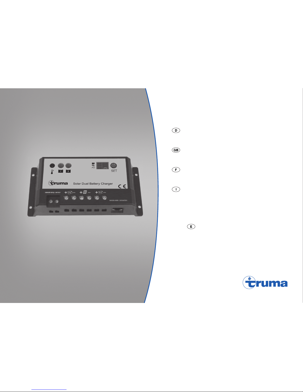
Solar Dual Battery Charger
SDC 10 / 20
Page 2
2
Solar Dual Battery Charger
SET
+–
F1
1
F2
2
G1
+
-
B1
X1 X2 X3 X4 X5
X1 - X4 max. Ø 4 mm²
X5 8-pin RJ-45
G2
+
-
No function
**
* > 10 mm²
+–
2
+–
1
remote temp. sensor
remote meter connection
A
Page 3
3
Solar Dual Battery Charger
148
154
50
76150
37.5
Ø 4
mm
+–+–
2
+–
1
remote temp. sensor
remote meter connection
SET
B
C
150 150
Page 4
4
Vor Anschluss und Inbetriebnahme des Gerätes unbedingt die Einbau- und Gebrauchsanweisung lesen!
Glossar
AGM-Batterie Blei-Säure-Batterie, bei der der
Elektrolyt in einem Mikroglasvlies
(absorbed glass mat) festgelegt ist.
Batterie OPTIMA® YT S entspricht einer AGM-Batterie.
Solar-Ladeautomat SDC 10 / 20
Gebrauchsanweisung
Inhaltsverzeichnis
Verwendete Symbole ............................................................ 4
Gebrauchsanweisung
Glossar .................................................................................. 4
Sicherheitshinweise .......................................................... 5
Verwendungszweck .......................................................... 5
Bestimmungswidriger Gebrauch .......................................... 6
Batteriepflege .................................................................... 6
Geräteelemente .................................................................. 6
Funktion ............................................................................... 7
Ladevorgang ....................................................................... 7
Einstellungen – abfragen / ändern .................................. 8
Bedienung ............................................................................. 8
Batterietyp ............................................................................. 8
Ladestromverteilung ............................................................ 9
PWM Ladefrequenz .............................................................. 9
Funktionsanzeige / Fehlersuchanleitung ..................... 10
Wartung ............................................................................. 10
Technisch e Daten ............................................................. 10
Ladediagramm .................................................................... 11
Entsorgung ........................................................................ 11
Hersteller-Garantieerklärung
(Europäische Union) ........................................................ 12
Einbauanweisung
Sicherheitshinweise ........................................................ 13
Lieferumfang .................................................................... 14
Montage ............................................................................ 14
Anschluss .......................................................................... 14
Anschlussplan ..................................................................... 15
Inbetriebnahme ................................................................ 15
Verwendete Symbole
Symbol weist auf mögliche Gefahren hin.
Hinweis mit Informationen und Tipps.
Page 5
5
Sicherheitshinweise
Beim Gebrauch von elektrischen Geräten sind zum
Schutz vor elektrischem Schlag, Verletzung und Brandgefahr folgende grundsätzliche Sicherheitsmaßnahmen zu
beachten. Lesen und beachten Sie diese Hinweise, bevor Sie
das Gerät benutzen.
Aufstellen
Achten Sie darauf, dass die Geräte sicher aufgestellt werden,
nicht herabfallen oder umstürzen können. Legen Sie Leitungen stets so, dass keine Stolpergefahr entsteht. Setzen Sie
Elektrogeräte nicht dem Regen aus. Betreiben Sie Elektrogeräte nicht in feuchter oder nasser Umgebung. Betreiben Sie
Elektrogeräte nicht in der Nähe von brennbaren Flüssigkeiten
oder Gasen.
Schutz vor elektrischem Schlag
Betreiben Sie nur Geräte deren Gehäuse und Leitungen unbeschädigt sind. Achten Sie auf sichere Verlegung der Kabel.
Ziehen Sie nicht an den Kabeln.
Solarmodule erzeugen bei Lichteinfall Strom. Auch bei geringem Lichteinfall steht die volle Spannung an. Die Leerlaufspannung kann doppelt so hoch sein. Keine stromführenden
Teile berühren. Solarmodule vor Montage- und Installationsarbeiten z. B. mit einem Karton abdecken.
Gebrauch
Dieses Gerät ist nicht dafür bestimmt durch Personen (einschließlich Kinder) mit eingeschränkten physischen, sensorischen oder geistigen Fähigkeiten oder mangels Erfahrung
und/ oder mangels Wissen benutzt zu werden, es sei denn,
sie werden durch eine für ihre Sicherheit zuständige Person
beaufsichtigt oder erhielten von ihr Anweisungen, wie das
Gerät zu benutzen ist.
Kinder sollten beaufsichtigt werden, um sicherzustellen, dass
sie nicht mit dem Gerät spielen.
Benutzen Sie keine elektrischen Geräte entgegen dem, vom
Hersteller angegebenen Verwendungszweck. Die Lüftungsschlitze am Gehäuse müssen frei sein und dürfen nicht durch
Gepäckstücke, Handtücher oder Kleidungsstücke etc. verdeckt werden.
Achtung
Batterien können explosive Gase beim Laden und während
des Betriebs erzeugen. Flammen und Zündquellen fernhalten.
Für eine ausreichende Belüftung des Batterieraumes sorgen.
Instandsetzung
Nehmen Sie keine Instandsetzungsarbeiten oder Veränderungen am Gerät vor. Wenden Sie sich an Ihren Händler oder an
den Truma Service (siehe www.truma.com).
Zubehör
Benutzen Sie nur Zubehörteile und Zusatzgeräte die vom
Hersteller geliefert oder empfohlen werden.
Verwendungszweck
Der Solar-Ladeautomat dient dem Laden von 12 V (24 V) Bleiakkumulatoren, bestehend aus 6 (12) Einzelzellen (z. B. Autobatterie), mit einer Kapazität von 50 – 100 Ah (SDC 10) bzw.
50– 200 Ah (SDC 20). Das Gerät wurde für den Anschluss
von Solarmodulen entwickelt. Nur geeignete Module z.B.
Truma SM65, SM100 oder SM150 verwenden. Die maximalen Spannungs- und Stromaufnahmewerte beachten. Das
bevorzugte Einsatzgebiet des Ladeautomaten sind Batterien
mit Gel-, AGM- oder Flüssigelektrolyt.
Das Gerät ist für den Einbau im Innenraum bestimmt.
Page 6
6
Bestimmungswidriger Gebrauch
Das Gerät ist nicht geeignet zum Laden von
– 6 V-Batterien oder 6 V-Bleiakkumulatoren,
– nicht-aufladbaren Batterien,
– Nickel-Cadmium-Batterien.
Werden Batterien mit einer Nennspannung von 6 V mit
diesem Gerät geladen, so setzt die Gasung sofort ein.
Es kann explosives Knallgas entstehen.
Das Gerät ist nur für die Regelung von Solarmodulen geeignet. Keine andere Spannungsquellen (z.B. Netzspannung
230V) an das Gerät anschließen. Dies kann zur Zerstörung
des Geräts und/oder der Quellen führen. Sollen andere Spannungsquellen zusammen mit dem Gerät genützt werden, fragen Sie Ihren Händler.
Batteriepflege
(auch wartungsfreie Batterien)
Um eine lange Batterielebensdauer zu erreichen, sind folgende Punkte zu beachten:
– Batterien sollten vor und nach einer Stromentnahme voll
aufgeladen werden.
– Bei längeren Stillstandszeiten
(ohne Sonneneinstrahlung),
muss die Batterie abgeklemmt und spätestens alle 12 Wochen für 24 Stunden geladen werden.
Im Winter voll geladene Batterien kühl und frostfrei
lagern und regelmäßig (alle 12 Wochen) nachladen.
Geräteelemente
Solar Dual Battery Charger
+–+–
2
+–
1
remote temp. sensor
remote meter connection
SET
H1 H2B2 T
H3
H4H5H6
X1 X2 X3 X4 X5
Bild 1: Geräteelemente
H1 LED- Funktionsanzeige Batterie 1 (Versorgungsbatterie)
H2 LED- Funktionsanzeige Batterie 2 (Starterbatterie)
H3 LED – Batterietyp – AGM, Gel, Liquid (Flüssigelektrolyt)
H4 LED – Ladestromverteilung
H5 LED – PWM Ladefrequenz
H6 zeigt die Werte von H3, H4, H5 als Nummer an
T Betriebsart abfragen / ändern
B2 Interner Temperaturfühler
X1 Anschluss für Temperaturfühler B1
X2 Anschluss Batterie 1 (Versorgungsbatterie)
X3 Anschluss Solarmodul
X4 Anschluss Batterie 2 (Starterbatterie)
X5 Ohne Funktion
Page 7

7
Funktion
Das Gerät ist mit moderner mikroprozessorgesteuerter pulsbreiten modulierter drei Phasen Ladetechnik ausgestattet.
Diese Technik ermöglicht hohe Leistung bei geringem Gewicht und kleinen Abmessungen. Durch Verwendung hochwertiger Elektronik arbeitet es mit einem hohen Wirkungsgrad. Das automatische Laden erfolgt schonend und ohne
schädliches Überladen der Batterien. So wird die Lebensdauer
der Batterien wesentlich verlängert. Es ist für Batterien mit
Flüssig-, Gel- oder AGM-Technologie geeignet und bietet
eine einstellbare Ladestromverteilung für zwei getrennte
Batterieanschlüsse.
Das Gerät ist für Dauerbetrieb und Parallelbetrieb konzipiert.
Verbraucher können ständig angeschlossen blei ben, dazugeschaltet oder weggeschaltet werden. Es werden gleichzeitig
die Verbraucher versorgt und die Batterien geladen. Der
Verbraucherstrom soll hierbei kleiner als der Solar-Ladestrom
sein, da sonst keine Ladung der Batterien erfolgt.
Wird das Gerät zusammen mit einem externen Temperaturfühler für die Versorgungsbatterie (Batterie 1) betrieben, so
regelt das Gerät die Ladespannung automatisch in Abhängigkeit der Batterietemperatur. Hierdurch wird eine besonders
effektive und schonende Ladung der Batterie erreicht. Ohne
Verwendung eines externen Temperaturfühlers regelt das Gerät den Ladevorgang anhand des internen Temperaturfühlers.
Durch den Anschluss von einem oder mehreren Solarmodulen können die Ver sorgungs- und die Starterbatterie geladen
werden. Beachten Sie hierbei die maximalen Spannungs- und
Stromaufnahmewerte.
Ladevorgang
Das Gerät besitzt einen elektronischen Verpolungs-, Rückstrom- und Solarkurzschlussschutz. Nur wenn die Batterie
richtig angeschlossen ist und ausreichend Leistung aus Sonnenlicht zur Verfügung steht, wird der Ladestrom freigegeben
(siehe „Ladediagramm“). Unter Verwendung eines Temperaturfühlers für die Versorgungsbatterie erfolgt der Ladevorgang
temperaturabhängig.
Hauptladephase
Ladung mit maximal verfügbarem Solar-Ladestrom bis die
Ladeendspannung erreicht wird.
Nachladephase
Die Ladespannung wird über eine Zeitdauer von 2 Stunden
gehalten. Nach Ablauf dieser Zeit erfolgt eine Umschaltung in
die Erhaltungsladephase.
Erhaltungsladephase
Die Ladespannung ist auf 13,8 V eingestellt. Der Ladestrom
sinkt dabei auf den für die Batterie zum Ausgleich der Selbstentladung notwendigen Wert ab. Verbraucher werden weiterhin versorgt. Übersteigt der verbrauchte Strom den verfügbaren Solar-Ladestrom, kann die Ladung nicht mehr aufrecht
erhalten werden.
Unterschreitet die Batteriespannung 13,3V schaltet das Gerät
– bei ausreichendem Solar-Ladestrom – automatisch in die
Hauptladephase.
Page 8
8
Ausgleichsladephase
(Nur bei Batterietyp AGM und Flüssigelektrolyt)
Die Ausgleichsladephase dient dem Ausgleich der Zellenspannungen und kann vorhandene Sulfatierungen vermindern.
Sinkt die Spannung an der Batterie unter 11,1V wird eine
Tiefentladung der Batterie angenommen. Das Gerät schaltet
für 2Stunden in die Ausgleichsladephase. Nach dieser Zeit
wechselt es automatisch in die Erhaltungsladephase.
– Tiefentladene Batterien können dauerhaft beschä-
digt werden. Eine Ausgleichsladung kann dies
nicht reparieren.
– Bei Flüssigelektrolytbatterien können explosive
Gase entstehen, sorgen sie für ausreichende Entlüftung. Überprüfen sie regelmäßig den Flüssigkeitsstand. Überladung kann Ihre Batterie beschädigen, überprüfen Sie die entsprechenden Daten
Ihrer Batterie.
– Die Ausgleichsladung erhöht die Ladespannung,
dies kann Verbraucher möglicherweise beschädigen. Stellen Sie sicher, das alle Verbraucher entsprechen dieser Spannungen ausgelegt sind.
Parallelbetrieb
Wird während der Batterieladung Verbraucherstrom entnommen, so wird dieser aus dem verfügbaren Solar-Ladestrom
bedient. Übersteigt der verbrauchte Strom den verfügbaren
Solar-Ladestrom, kann das Gerät die Batterie nicht laden. Das
Gerät beginnt automatisch mit der Ladung, wenn wieder ausreichend Solar-Ladestrom verfügbar ist.
Einstellungen – abfragen / ändern
Bedienung
Die Anzeige H6 zeigt verschiedene Systemeinstellungen an.
Durch kurzes Drücken der Taste (T) wird zwischen LED H3, H4
und H5 gewechselt und in H6 angezeigt. Durch nochmaliges
Drücken beginnt man wieder bei LED H3.
Batterietyp
Der Batterietyp kann nur für die Batterie 1 eingestellt werden,
die Batterie 2 wird als gleicher Batterietyp angenommen.
Abfragen
– Taste (T) drücken bis LED H3 leuchtet, in
Anzeige H6 wird der gespeicherte Wert angezeigt.
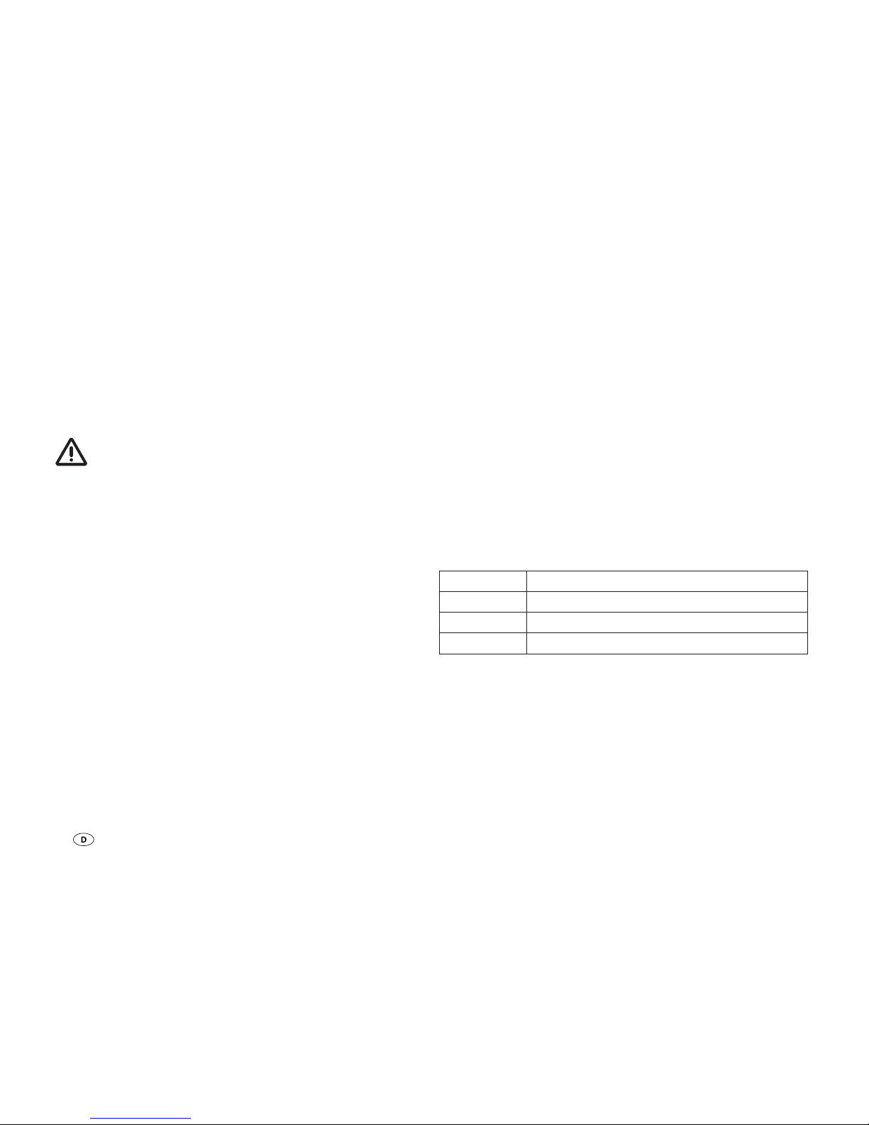
Anzeige H6 Batterietyp
1 Gel (Voreinstellung)
2 AGM
3 Flüssig (Flüssigelektrolyt )
Ändern
– Taste (T) für 5 Sekunden drücken, bis die Anzeige H6 blinkt.
– Durch Drücken der Taste (T) den gewünschten Wert
einstellen.
– Nach 5 Sekunden ohne Tastendruck wird der angezeigte
Wert gespeichert und das Blinken endet.
Page 9
9
Ladestromverteilung
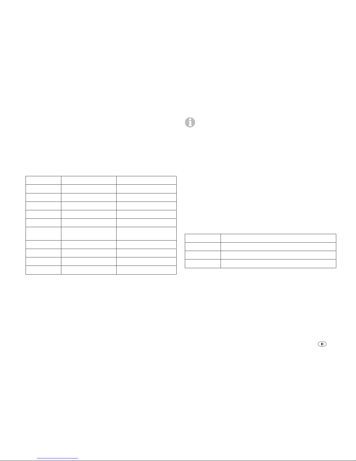
Die Ladestromverteilung zwischen Batterie1 und Batterie2
kann eingestellt werden. Folgende Verteilungen können gewählt werden.
Abfragen
– Taste (T) drücken bis LED H4 leuchtet, in
Anzeige H6 wird der gespeicherte Wert angezeigt.
Anzeige H6 Batterie 1 Batterie 2
0 0 % 100 %
1 10 % 90 %
2 20 % 80 %
3 30 % 70 %
4 40 % 60 %
5 50 %
(Voreinstellung)
50 %
6 60 % 40 %
7 70 % 30 %
8 80 % 20 %
9 90 % 10 %
Ändern
– Taste (T) für 5Sekunden drücken, bis die Anzeige H6 blinkt.
– Durch Drücken der Taste (T) den gewünschten Wert
einstellen.
– Nach 5Sekunden ohne Tastendruck wird der angezeigte
Wert gespeichert und das Blinken endet.
Beim normalen Ladevorgang, teilt das Gerät den Lade-
strom zwischen Batterie 1 und Batterie 2, wie eingestellt,
auf. Ist die Batterie 1 voll geladen, wird der gesamte Ladestrom in die Batterie 2 geleitet, unabhängig vom eingestellten
Wert. Sinkt die Spannung an der Batterie1, beginnt der Ladevorgang erneut. Ist nur die Batterie1 angeschlossen, wird
der gesamte Ladestrom in diese Batterie geleitet, unabhängig
vom eingestellten Wert.
PWM Ladefrequenz
Hiermit kann die Pulsfrequenz des Geräts eingestellt werden.
Diese kann zur Verringerung möglicher Interferenzen geändert
werden.
Abfragen
– Taste (T) drücken bis LED H5 leuchtet, in
Anzeige H6 wird der gespeicherte Wert angezeigt.
Anzeige H6 PWM Ladefrequenz
0 25 Hz (Voreinstellung)
1 50 Hz
2 100 Hz
– Taste (T) für 5Sekunden drücken, bis die Anzeige H6 blinkt.
– Durch Drücken der Taste (T) den gewünschten Wert
einstellen.
– Nach 5Sekunden ohne Tastendruck wird der angezeigte
Wert gespeichert und das Blinken endet.
Page 10
10
Funktionsanzeige / Fehlersuchanleitung
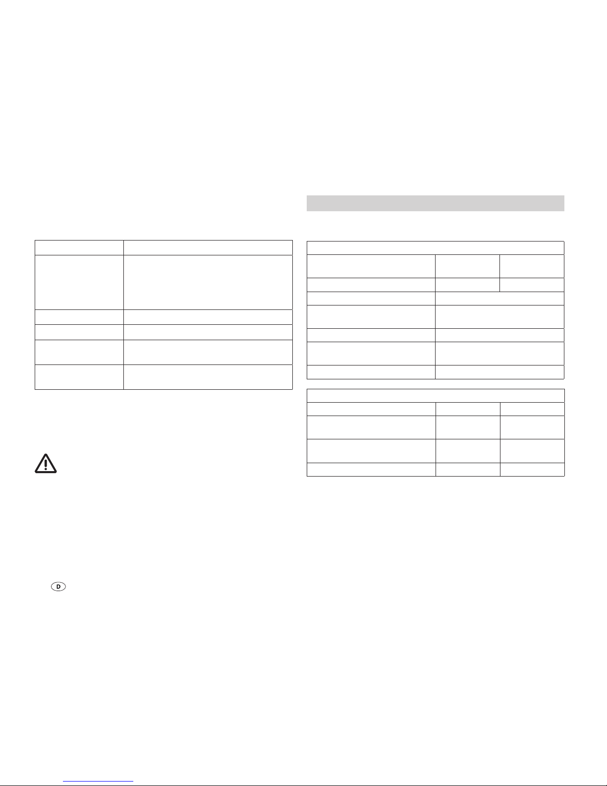
Die LED H1 (H2) zeigt den Status von Batterie 1 (Batterie 2) an.
Anzeige Ursache / Behebung
LED blitzt in langen
Zeitabständen
Anschlüsse vom Gerät zur Batterie
und Solarmodul prüfen, auf die richtige Polung achten.
Sicherung, Solarmodul und Batterie
prüfen.
LED blinkt Batterie ist voll geladen.
LED leuchtet Batterie wird geladen.
LED blitzt in kurzen
Zeitabständen
Batterie wird nicht geladen.
Ggf. defekte Batterie tauschen.
LED leuchtet nicht Keine Batterie angeschlossen oder
Überspannung.
Sollten diese Maßnahmen nicht zur Störungsbehebung führen, wenden Sie sich bitte an den Truma Service.
Wartung
Vor allen Wartungsarbeiten am Gerät unbedingt die
Stromzufuhr unterbrechen. Solarmodule z. B. mit einem
Karton abdecken.
Reinigen Sie das Gerät mit einem trockenen, fusselfreien Tuch.
Technische Daten
* Angaben für 12V – für 24V Werte verdoppeln.
Elektrische Werte
Betriebsspannung
automatische Erkennung
12V 24V
max. Eingangsspannung 30V 50V
Spannungsbereich * 8 – 15V
zul. Umgebungstemperatur-
bereich
-35°C – +55°C
zul. Lagertemperaturbereich -35°C – +80°C
Eigenverbrauch 4mA nachts,
10mA beim Laden
PWM-Frequenz, einstellbar 25Hz, 50Hz, 100Hz
Ströme
SDC10 SDC20
max. Modulstrom
dauernd bei 25°C
10A
(ca. 150Wp)
20A
(ca. 300Wp)
max. Ausgangsstrom
dauernd bei 25°C
10A 20A
Batteriekapazität 50 – 100Ah 50 – 200Ah
Page 11
11
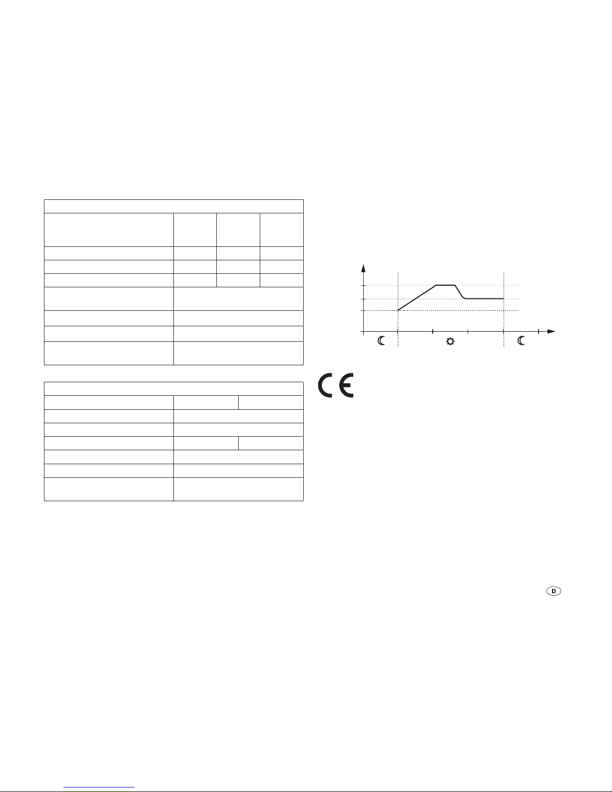
Ladespannungen
Batterietyp, einstellbar Gel AGM
Verschlossen
Flüssig
Nachladephase * 14,2 V 14,4 V 14,6 V
Erhaltungsladephase * 13,8 V 13,8 V 13,8V
Ausgleichsladephase * – 14,6 V 14,8 V
Hauptladephase
Umschaltspannung *
13,3V
Maximale Ladespannung * 16,6V
Temperaturkompensation * -30mV / K
Temperaturfühler
(Meßbereich)
-40°C – +125°C
Mechanische Werte
SDC10 SDC20
Schutzart IP30
Montage Wandmontage
Gewicht 200g 230g
Anschlussklemmen 4mm²
Abmessungen L x B x H 154 x 76 x 37,5 mm
Feuchtigkeit
(nicht kondensierend)
95%
Ladediagramm
HL = Hauptladephase
NL = Nachladephase (2 Stunden)
EL = Erhaltungsladung
U
EL
0
U[V]
U
NL
t[h]
ELNLHL
U
HL
Bild 2: Ladediagramm (prinzipieller Verlauf)
Technische Änderungen vorbehalten!
Entsorgung
Das Gerät ist gemäß den administrativen Bestimmungen
des jeweiligen Verwendungslandes zu entsorgen. Nationale
Vorschriften und Gesetze (in Deutschland ist dies z. B. die
Altfahrzeug-Verordnung) müssen beachtet werden.
Page 12

12
Hersteller-Garantieerklärung
(Europäische Union)
1. Umfang der Herstellergarantie
Truma gewährt als Hersteller des Gerätes dem Verbraucher
eine Garantie, die etwaige Material- und/oder Fertigungsfehler
des Gerätes abdeckt.
Diese Garantie gilt in den Mitgliedsstaaten der europäischen
Union sowie in den Ländern Island, Norwegen, Schweiz und
Türkei. Verbraucher ist die natürliche Person, die als erstes das
Gerät vom Hersteller, OEM oder Fachhändler erworben hat und
es nicht im Rahmen einer gewerblichen oder selbständigen
beruflichen Tätigkeit weiterveräußert oder bei Dritten installiert.
Die Herstellergarantie gilt für die oben genannten Mängel, die
innerhalb der ersten 24 Monate seit Abschluss des Kaufvertrages zwischen dem Verkäufer und dem Verbraucher eintreten.
Der Hersteller oder ein autorisierter Servicepartner wird solche Mängel durch Nacherfüllung, das heißt nach seiner Wahl
durch Nachbesserung oder Ersatzlieferung, beseitigen. Defekte
Teile gehen in das Eigentum des Herstellers bzw. des autorisierten Servicepartners über. Sofern das Gerät zum Zeitpunkt der
Mangelanzeige nicht mehr hergestellt wird, kann der Hersteller
im Fall einer Ersatzlieferung auch ein ähnliches Produkt liefern.
Leistet der Hersteller Garantie, beginnt die Garantiefrist hinsichtlich der reparierten oder ausgetauschten Teile nicht von
neuem, sondern die alte Frist läuft für das Gerät weiter.
Zur Durchführung von Garantiearbeiten sind nur der Hersteller
selbst oder ein autorisierter Servicepartner berechtigt. Die im
Garantiefall anfallenden Kosten werden direkt zwischen dem
autorisierten Servicepartner und dem Hersteller abgerechnet.
Zusätzliche Kosten aufgrund erschwerter Aus- und Einbaubedingungen des Gerätes (z. B. Demontage von Möbel- oder
Karosserieteilen) sowie Anfahrtskosten des autorisierten
Servicepartners oder Herstellers können nicht als Garantieleistung anerkannt werden.
Weitergehende Ansprüche, insbesondere Schadensersatzansprüche des Verbrauchers oder Dritter, sind ausgeschlossen. Die Vorschriften des Produkthaftungsgesetzes bleiben
unberührt.
Die geltenden gesetzlichen Sachmängelansprüche des Verbrauchers gegenüber dem Verkäufer im jeweiligen Erwerbsland
bleiben durch die freiwillige Garantie des Herstellers unberührt.
In einzelnen Ländern kann es Garantien geben, die durch die
jeweiligen Fachhändler (Vertragshändler, Truma Partner) ausgesprochen werden. Diese kann der Verbraucher direkt über
seinen Fachhändler, bei dem er das Gerät gekauft hat, abwickeln. Es gelten die Garantiebedingungen des Landes, in dem
der Ersterwerb des Gerätes durch den Verbraucher erfolgt ist.
2. Ausschluss der Garantie
Der Garantieanspruch besteht nicht:
– infolge unsachgemäßer Verwendung entgegen dem bestim-
mungsmäßigen Verwendungszweck
– infolge unsachgemäßer Installation, Montage oder Inbe-
triebnahme entgegen der Gebrauchs- und Einbauanweisung
– infolge unsachgemäßem Betrieb oder Bedienung entgegen
der Gebrauchs- und Einbauanweisung, insbesondere bei
Missachtung von Wartungs-, Pflege- und Warnhinweisen
– wenn Reparaturen, Installationen oder Eingriffe von nicht
autorisierten Partnern durchgeführt werden
– für Verbrauchsmaterialien, Verschleißteile und bei natürli-
cher Abnutzung
– wenn das Gerät mit Ersatz-, Ergänzungs- oder Zubehörtei-
len versehen wird, die keine Originalteile des Herstellers
sind und dadurch ein Mangel verursacht wird
Page 13
13
– infolge von Schäden durch Fremdstoffe (z. B. Öle, Weich-
macher im Gas), chemische oder elektrochemische Einflüsse im Wasser oder wenn das Gerät sonst mit ungeeigneten
Stoffen in Berührung gekommen ist (z. B. chemische Produkte, ungeeignete Reinigungsmittel)
– infolge von Schäden durch anormale Umwelt- oder sach-
fremde Betriebsbedingungen
– infolge von Schäden durch höhere Gewalt oder Naturkatas-
trophen, sowie durch andere Einflüsse die nicht von Truma
zu verantworten sind
– infolge von Schäden, die auf unsachgemäßen Transport zu-
rückzuführen sind
3. Geltendmachung der Garantie
Die Garantie ist bei einem autorisierten Servicepartner oder
beim Truma Servicezentrum geltend zu machen. Alle Adressen und Telefonnummern finden Sie unter www.truma.com
im Bereich „Service“.
Um einen reibungslosen Ablauf zu gewährleisten, bitten wir bei
Kontaktaufnahme die folgenden Informationen bereit zu halten:
– detaillierte Mangelbeschreibung
– Seriennummer des Gerätes
– Kaufdatum
Der autorisierte Servicepartner oder das Truma Servicezentrum
legen jeweils die weitere Vorgehensweise fest. Um eventuelle
Transportschäden zu vermeiden, darf das betroffene Gerät nur
nach vorheriger Rücksprache mit dem autorisierten Servicepartner oder dem Truma Servicezentrum versendet werden.
Wenn der Garantiefall vom Hersteller anerkannt wird, übernimmt der Hersteller die Transportkosten. Liegt kein Garantiefall vor, wird der Verbraucher entsprechend informiert und die
Reparatur- und Transportkosten gehen zu seinen Lasten.
Von Einsendungen ohne vorherige Rücksprache bitten wir
abzusehen.
Sicherheitshinweise
In diesem Gerät sind Bauteile eingebaut, die einen
Funken oder Lichtbogen erzeugen können!
Die Montage und der Anschluss von elektrischen Geräten
muss grundsätzlich durch geeignetes Fachpersonal erfolgen!
Solarmodule erzeugen bei Lichteinfall Strom. Auch bei geringem Lichteinfall steht die volle Spannung an. Die Leerlaufspannung kann doppelt so hoch sein. Keine stromführenden
Teile berühren. Solarmodule vor Montage- und Installationsarbeiten z. B. mit einem Karton abdecken.
Das Gerät wurde für den Anschluss von Solarmodulen entwickelt. Nur geeignete Module z. B. Truma SM65, SM100 oder
SM150 verwenden. Die maximalen Spannungs- und Stromaufnahmewerte beachten.
Nur vorgeschriebene Leitungsquerschnitte und Sicherungsstärken verwenden!
Das Gerät nicht in Feuchträumen (z.B. Bäder) oder in Räumen, in denen leicht entzündliche Gasgemische entstehen
können installieren oder betreiben.
Der Einbau des Gerätes muss den technischen und administrativen Bestimmungen des jeweiligen Verwendungslandes
entsprechen (z. B. EN1648). Nationale Vorschriften und Regelungen müssen beachtet werden.
Einbauanweisung
Page 14
14
Lieferumfang
– 1 Solar-Ladeautomat
– 1 Temperaturfühler
– 1 Halter für Temperaturfühler
– 1 Gebrauchs- und Einbauanweisung
Montage
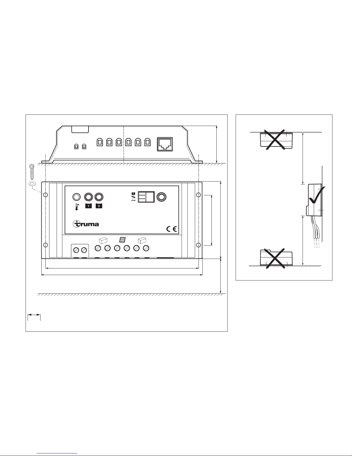
Siehe Seite 3, Bild B, C
Das Gerät ist vor Feuchtigkeit und Nässe geschützt aufzustellen. Der Aufstellungsort muss sauber, trocken und gut
belüftet sein. Bei Betrieb kann sich das Gehäuse auf ca. 80 °C
erwärmen.
Achten sie darauf, dass die Lüftungsschlitze frei bleiben! Unzureichende Belüftung kann zur Überhitzung
des Gerätes führen!
Der Einbauraum für das Gerät muss oben und seitlich mit
Lüftungsöffnungen versehen sein, die eine Gesamtöffnung
von 100 cm² ergeben.
Steigt die Geräteinnentemperatur durch mangelnde Luftzirkulation oder zu hohe Umgebungstemperatur, kann das Gerät
beschädigt werden.
Flüssigelektrolytbatterien müssen in einer separaten Box mit
einer Entlüftung nach außen aufgestellt werden. Eine separate
Box ist bei Gel- und AGM-Batterien nicht notwendig. Die Installationsvorschriften des Batterieherstellers beachten.
Das Gerät mit vier Schrauben (Durchmesser 4 mm – keine
Senkkopfschrauben) sicher befestigen. Schraubenlänge und
Drehmoment abhängig vom Untergrund.
Anschluss
Leitungslängen und -querschnitte
Ausführung gemäß EN 1648-1 und VDE 0100, Teil 721.
Sicherungen F1, F2
SDC 10 – 15A
SDC 20 – 30A
Sicherungen unbedingt nahe der Energiequelle
(z. B. Batterie) anbringen. Nur vorgeschriebene Lei-
tungsquerschnitte und Sicherungsstärken verwenden!
Anschluss Energiequelle / Verbraucher
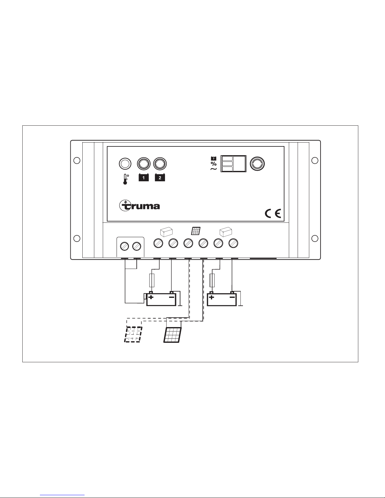
Verbinden Sie das Gerät gemäß Anschlussplan mit den Solarmodulen und den Batterien. Achten Sie auf den richtigen
Anschluss der Pole.
Verschalten Sie mehrere Solarmodule immer parallel. Verwenden Sie hierzu nur Module gleicher typischer Spannungswerte (ca. 18V). Fragen Sie Ihren Händler nach dem Truma
KabelsetErweiterung.
Anschlussreihenfolge beachten. Die automatische
Anpassung 12V / 24V funktioniert nur in diesem Fall
korrekt und es können Schäden an der Batterie verhindert
werden.
1. Batterie 1 (2) an den Laderegler anschließen –
Plus und Minus
2. Solarmodule an den Laderegler anschließen –
Plus und Minus
3. Temperaturfühler an den Laderegler anschließen –
Plus und Minus
Bei der Deinstallation gilt die umgekehrte Reihenfolge.
Page 15
15
Temperaturfühler
Für eine temperaturgeführte Batterieladung verwenden Sie
den beiliegenden Truma Temperaturfühler, insbesondere bei
AGM-Batterien.
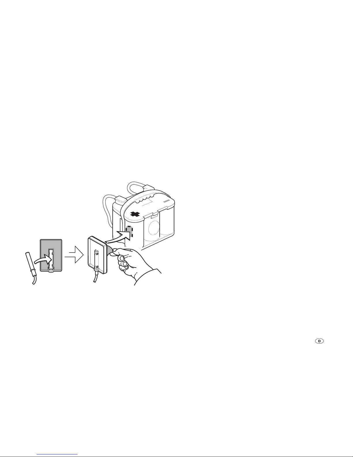
Bringen Sie den Fühler mittig im Bereich des Pluspols, am
Gehäuse der Batterie (1) an. Dazu den Fühler mittig in der
Aussparung des Halters platzieren. Die Schutzfolie des selbstklebenden Halters entfernen. Den Halter kräftig auf die gewünschte Position an der Batterie drücken.
Temp. Sensor Fixer
TSF - 01
Bild 3: Montage des Temperaturfühlers
Temperaturfühler (B1) am Gerät anschließen (Anschluss X1).
Kabelfixierung
Alle Leitungen (z. B. zu Energiequellen, Verbrauchern und
Zubehör) mit Kabelbindern sichern.
Anschlussplan
Siehe Seite 2, BildA
Inbetriebnahme
Das Gerät ist in Betrieb, sobald eine Batterie oder ein Solarmodul angeschlossen ist (Anschlussreihenfolge beachten).
Batterietyp einstellen
Den verwendeten Batterietyp (Batterie 1) einstellen (siehe „Einstellungen abfragen / ändern – Batterietyp“).
Einbauanweisung
Page 16
16
Please be sure to read the instructions for installation and
use before attempting to connect and use this device!
Glossary
AGM-battery Lead acid battery, in which the elec-
trolyte is set in an absorbed glass
mat.
Battery OPTIMA® YT S corresponds to an AGM-battery.
Solar Dual Battery Charger SDC 10 / 20
Operating instructions
Table of contents
Symbols used ...................................................................... 16
Operating instructions
Glossary .............................................................................. 16
Safety instructions .......................................................... 17
Intended use ..................................................................... 17
Improper use ....................................................................... 18
Battery care ...................................................................... 18
Device elements ............................................................... 18
Function ............................................................................. 19
Charging process ............................................................. 19
Settings – query / change ............................................... 20
Operation ............................................................................ 20
Battery type ......................................................................... 20
Charging current distribution .............................................. 21
PWM charging frequency ................................................... 21
Function display / troubleshooting ............................... 22
Maintenance ..................................................................... 22
Technical dat a ................................................................... 22
Charging chart .................................................................... 23
Disposal ............................................................................. 23
Manufacturer’s Warranty
(European Union) .............................................................. 24
Installation instructions
Safety instructions .......................................................... 25
Delivery scope .................................................................. 26
Assembly ........................................................................... 26
Connection ........................................................................ 26
Wiring diagram ................................................................... 27
Commissioning ................................................................. 27
Symbols used
Symbol indicates a possible hazard.
Comment including information and tips.
Page 17
17
Safety instructions
To protect you from electrical shocks, injury or burns
the following basic safety principles must be observed
when using electrical devices. Please read and follow these
instructions before using the device.
Installation
Ensure that the devices are positioned safely and cannot fall
down or over. Always position the cables to ensure they do
not pose a tripping hazard. Do not expose electrical devices to
rain. Do not operate electrical devices in damp or wet environments. Do not operate electrical devices close to flammable
liquids or gases.
Protection against electrical shocks
Only operate devices with undamaged casings and cables.
Ensure the cables are installed safely. Do not pull on the
cables.
The solar module generates power when light is cast on it.
The full voltage is also available even if there is little light. The
open circuit voltage may be twice as high. Do not touch any
live parts. Cover solar modules with e.g. cardboard, before
mounting and installing.
Use
This device has not been designed for use by people (including children) who have restricted physical, sensory or mental
abilities or a lack of experience and/or knowledge, unless they
are supervised by a person responsible for their safety or have
received instructions from that person as to how the device is
to be used.
Children should be supervised to ensure they do not play with
the device.
Do not use electrical devices for purposes other than those
stated by the manufacturer. The ventilation slits in the housing
must be free and may not be covered by luggage, towels or
clothing etc.
Caution
Batteries may generate explosive gases during charging and
operation. Keep away from flames and ignition sources. Ensure there is sufficient ventilation in the battery chamber.
Repairs
Do not repair or modify the device. Please contact your dealer
or the Truma Service (see www.truma.com).
Accessories
Only use accessories and additional devices that are supplied
or recommended by the manufacturer.
Intended use
The solar automatic charger only serves to charge 12 V (24 V)
lead accumulators comprising 6 (12) single cells (e.g. car battery) with a capacity of 50 – 100 Ah (SDC 10) or 50 – 200 Ah
(SDC 20). The device was developed for connection to solar
modules. Only use suitable modules e.g. Truma SM 65, SM 100
or SM 150. Observe the maximum voltage and power draw
values. The preferred application fields for the automatic
charger are batteries with gel, AGM or liquid electrolyte.
The device is designed for installation inside.
Page 18
18
Improper use
The device is not suitable for charging
– 6 V batteries or 6 V lead accumulators
– non-chargeable batteries
– nickel-cadmium batteries.
If batteries with a rated voltage of 6 V are charged with the
device, gassing occurs immediately. An explosive gas can be
created.
The device is only suitable for regulating solar modules. Do
not connect any other voltage sources (e.g. main voltage
230V) to the device. This may destroy the device and/or
sources. If any other voltage sources are used together with
the device, please ask your dealer.
Battery care
(also maintenance-free batteries)
The following points should be observed to extend the
battery life:
– Batteries should be fully charged before and after being
used.
– In the case of longer standstills (without sunshine), discon-
nect the battery and charge for 24 hours at the latest every
12 weeks.
Store fully charged batteries in a cool but frost-free place
during the winter and recharge regularly (every 12 weeks).
Device elements
Solar Dual Battery Charger
+–+–
2
+–
1
remote temp. sensor
remote meter connection
SET
H1 H2B2 T
H3
H4H5H6
X1 X2 X3 X4 X5
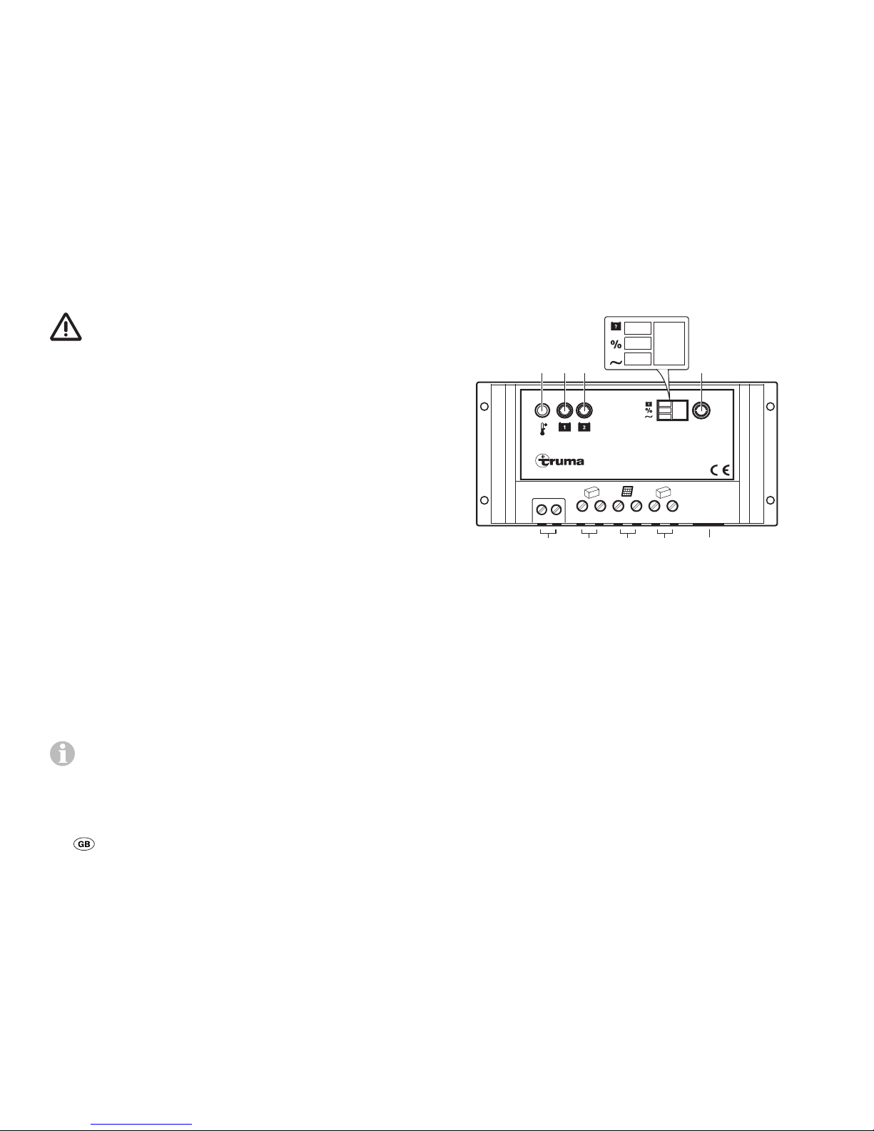
Fig. 1: Device elements
H1 LED- Function display battery 1 (supply battery)
H2 LED- Function display battery 2 (starter battery)
H3 LED – Battery type - AGM, gel, liquid (liquid electrolyte)
H4 LED – Charging current distribution
H5 LED – PWM charging frequency
H6 shows the values of H3, H4, H5 as numbers
T Query / change operating mode
B2 Internal temperature sensor
X1 Connection for temperature sensor B1
X 2 Connection for battery 1 (supply battery)
X3 Connection solar module
X4 Connection battery 2 (starter battery)
X5 No function
Page 19

19
Function
The device has a modern microprocessor-controlled pulse
width modulated three phase charging characteristic. This
allows high performance combined with a light weight and
small dimensions. By virtue of the high-quality electronics, it
works highly efficiently. The automatic charging process preserves the device and does not overcharge the batteries. This
in turn extends the service life of the batteries significantly.
It is suitable for batteries with liquid, gel or AGM technology
and has a settable charging current distribution for two separate battery connections.
The device is designed for continuous operation and parallel
mode. Consumers can be continuously connected, switched
on or disconnected. Consumers are supplied and the batteries are charged at the same time. The consumer current here
should be smaller than the solar charging current as otherwise the battery will not charge.
If the device is operated in conjunction with an external temperature sensor for the supply battery (battery 1), the device
regulates the charging voltage automatically depending on
the battery temperature. This ensures particularly effective
and gentle charging of the battery. If an external temperature
sensor is not used, the device regulates the charging process
based on the internal temperature sensor.
The supply and starter batteries can be charged by connecting one or several solar modules. Please observe the maximum voltage and power consumption values.
Charging process
The device has an electronic reverse voltage, reverse current
and solar short-circuit protection. The charging current is only
released (see “charging diagram”) if the battery is connected
correctly and there is enough power available from sunlight.
When a temperature sensor is used, charging takes place on
a temperature-dependent basis.
Bulk phase
Charging with maximum available solar charging current until
the charging end voltage is reached.
Absorption phase
The charging current is kept for a period of 2 hours. At the
end of this period, it changes to the float phase.
Float phase
The charging voltage is set to 13.8 V. The charging current drops to the value necessary to compensate the selfconsumption of the battery. Power is still supplied to the
consumers. If the consumed current exceeds the available
solar charging current, the charging process can no longer be
maintained.
If the battery voltage drops below 13.3 V, the device automatically switches to the bulk phase, if there is adequate solar
charging current.
Page 20
20
Equalisation charging phase
(only for AGM and liquid electrolyte battery type)
The equalisation charging phase serves to compensate the
cell voltages and can reduce any sulphation.
If the voltage of the battery drops below 11.1 V, it is assumed
that the battery has deep-discharged. The device is switched
to the equalisation charging phase for two hours. At the end
of this period, it changes automatically to the float phase.
– Deep-discharged batteries can be permanently
damaged. Equalisation charging cannot repair
this.
– Liquid electrolyte batteries can create explosive
gases, so ensure there is adequate ventilation.
Check the liquid level at regular intervals. Overcharging can damage your battery; check the
technical data for your battery.
– Equalisation charging increases the charging volt-
age; this may damage the consumer. Ensure that
all consumers are designed for these voltages.
Parallel mode
If load current is consumed whilst the battery is being
charged, it is served from the available solar charging current.
If the consumed current exceeds the available solar charging current, the device cannot charge the battery. The device
starts charging automatically once an adequate amount of
solar charging current is available again.
Settings – query / change
Operation
The display H6 shows different system settings. Press the
key(T) to switch between LED H3, H4 and H5 and display this
in H6. If the key is pressed again, the system starts at LED H3
again.
Battery type
The battery type can only be set for battery 1, battery 2 is assumed to be the same battery type.
Query
– Press (T) until LED H3 illuminates;
the saved value is shown in display H6.
Display H6 Battery type
1 Gel (pre-setting)
2 AGM
3 Liquid (liquid electrolyte)
Change
– Press key (T) for 5 seconds until the display H6 flashes.
– Press the key (T) to set the required value.
– If the key is not pressed for 5 seconds, the displayed value
will be saved and flashing stops.
Page 21
21
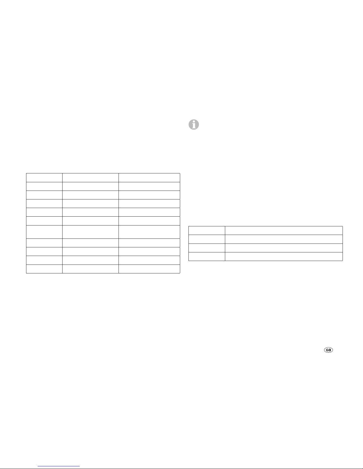
Charging current distribution
The charging current distribution between battery 1 and battery 2 can be set. The following distributions can be selected.
Query
– Press (T) until LED H4 illuminates; the saved value is shown
in display H6.
Display H6 Battery 1 Battery 2
0 0 % 100 %
1 10 % 90 %
2 20 % 80 %
3 30 % 70 %
4 40 % 60 %
5 50 %
(pre-setting)
50 %
6 60 % 40 %
7 70 % 30 %
8 80 % 20 %
9 90 % 10 %
Change
– Press key (T) for 5 seconds until the display H6 flashes.
– Press the key (T) to set the required value.
– If the key is not pressed for 5 seconds, the displayed value
will be saved and flashing stops.
During the normal charging process, the device divides
the charging current between battery 1 and battery 2
as set. Once the battery 1 is fully charged, all the charging
current is fed to battery 2, regardless of the set value. If the
voltage of battery 1 drops, the charging process starts again.
If only battery 1 is connected, the entire charging current is
supplied to this battery regardless of the set value.
PWM charging frequency
The pulse frequency of the device can be set here. This may
be changed to reduce possible interferences.
Query
– Press (T) until LED H5 illuminates; the saved value is shown
in display H6.
Display H6 PWM charging frequency
0 25 Hz (pre-setting)
1 50 Hz
2 100 Hz
– Press key (T) for 5 seconds until the display H6 flashes.
– Press the key (T) to set the required value.
– If the key is not pressed for 5 seconds, the displayed value
will be saved and flashing stops.
Page 22
22
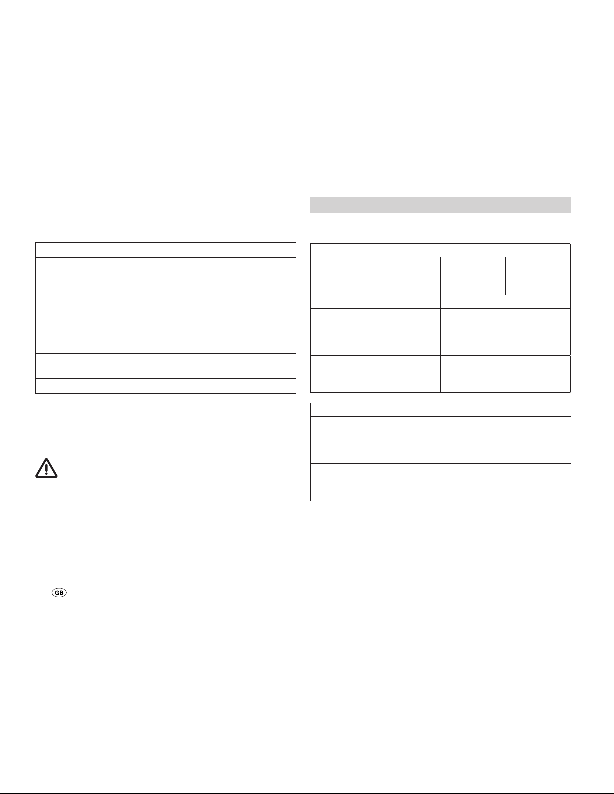
Function display / troubleshooting
LED H1 (H2) shows the status of battery 1 (battery 2).
Display Cause / rectification
LED flashes in
longer intervals
Check connections from the device to
the battery and solar module, ensure
that they are connected to the right
terminals.
Test the fuse, solar module and the
battery.
LED flashes Battery is fully charged.
LED shines. The battery is being charged.
LED flashes in
short intervals
The battery is not being charged.
If necessary, replace faulty battery.
LED does not shine Battery not connected or over-voltage
If this does not solve the problem, please contact the Truma
Service.
Maintenance
The power supply must always be disconnected before
performing any maintenance work. For example cover
the solar module with a cardboard box.
Clean the device with a dry and lint-free cloth.
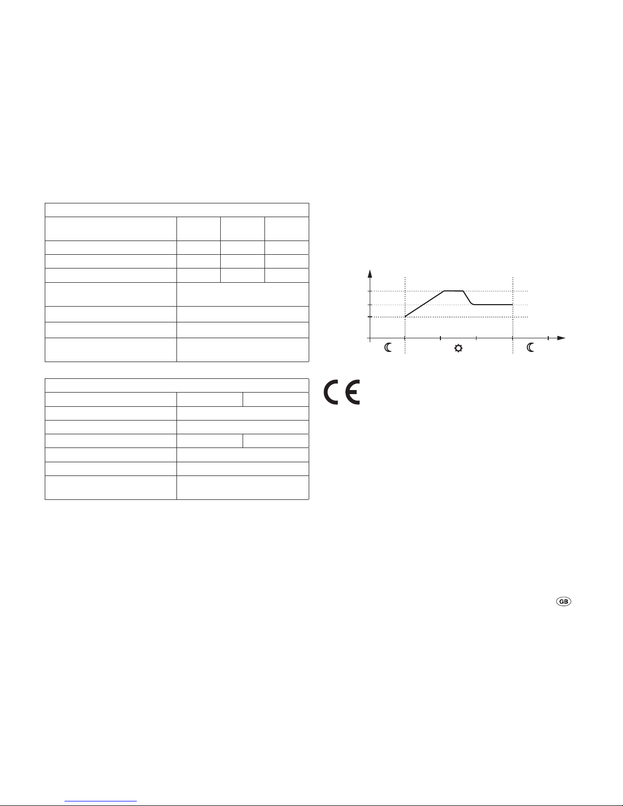
Technical data
* Double the values of the 12 V – to work out the 24 V values.
Electrical values
Operating voltage
Automatic recognition
12 V 24 V
max. input voltage 30 V 50 V
Voltage range * 8 – 15 V
Allowed ambient tempera-
ture range
-35 °C – +55 °C
Allowed storage temperature
range
-35 °C – +80 °C
Self-consumption 4 mA at night
10 mA during charging
PWM frequency, settable 25 Hz, 50 Hz, 100 Hz
Currents
SDC 10 SDC 20
max. module current
constant at 25 °C
10 A
(approx.
150 Wp)
20 A
(approx.
300 Wp)
max. output current
constant at 25 °C
10 A 20 A
Battery capacity 50 – 100 Ah 50 – 200 Ah
Page 23
23
Charging voltage
Battery type, settable Gel AGM
sealed
Liquid
Absorbtion phase * 14,2 V 14,4 V 14,6 V
Float phase * 13,8 V 13,8 V 13,8 V
Equalisation charging phase * – 14,6 V 14,8 V
Bulk phase reconnection
voltage *
13,3V
Maximum charging voltage * 16,6V
Temperature compensation * -30 mV / K
Temperature sensor
(measuring range)
-40°C – +125°C
Mechanical values
SDC 10 SDC 20
Protection type IP 30
Installation Wall mounted
Weight 200 g 230 g
Connection terminals 4 mm²
Dimensions L x W x H 154 x 76 x 37,5 mm
Humidity
(not condensing)
95 %
Charging chart
HL = Bulk phase
NL = Absorbtion phase (2 hours)
EL = Float phase
U
EL
0
U[V]
U
NL
t[h]
ELNLHL
U
HL
Fig. 2: Charging chart (basic curve)
The right to effect technical modifications is reserved!
Disposal
The device must be disposed of in line with the administrative regulations of the respective country in which it is used.
National regulations and laws (in Germany, for example, the
End-of-life Vehicle Regulation) must be observed.
Page 24

24
Manufacturer’s Warranty
(European Union)
1. Scope of Manufacturer’s Warranty
As the Manufacturer of the unit, Truma undertakes a warranty
towards the Consumer that covers any material and/or manufacturing defects of the unit.
This Warranty is applicable in EU member states as well as in
Iceland, Norway, Switzerland and Turkey. A Consumer is the
natural person who was the first one to purchase the unit from
the Manufacturer, OEM or dealer and who neither resold the
unit in a commercial or self-employed professional capacity
nor did he or she install it for a third party in such a capacity.
The Manufacturer’s Warranty covers any of the aforementioned
defects that occur within 24 months upon concluding the
purchase agreement between the seller and the Consumer.
The Manufacturer or an authorised service partner undertakes
to remedy such defects through subsequent fulfilment, i.e.
at its discretion either by repairing or replacing the defective
item. Any defective parts shall become the property of the
Manufacturer or the authorised service partner. If the unit is
no longer manufactured at the time of defect notification and
if replacement delivery has been opted for, then the Manufacturer may deliver a similar product.
If the Manufacturer remedies a defect under its warranty commitment, the term of the Warranty shall not recommence anew
with regard to the repaired or replaced parts; rather, the original warranty period shall continue to be applicable to the unit.
Only the Manufacturer itself and an authorised service partner
shall be entitled to conduct a warranty job. Any costs that occur in the event of a warranty claim shall be settled directly
between the authorised service partner and the Manufacturer.
The Warranty does not cover additional costs arising from
complicated removal or installation jobs on the unit (e.g. dismantling of furnishings or parts of the vehicle body), and neither does it cover travel expenses incurred by the authorised
service partner or the Manufacturer.
No further-reaching claims shall be permitted, especially damage claims presented by the Consumer or third parties. This
provision shall not affect the validity of the German Product
Liability Act (Produkthaftungsgesetz).
Neither does the voluntary Manufacturer’s Warranty affects
the Consumer’s legally applicable claims for defects towards
the seller in the relevant country of purchase. In individual
countries there may be warranties that can be issued by the
relevant dealer (official distributor, Truma Partner). In such
cases the warranty can be implemented directly through the
dealer from whom the Consumer bought the unit. The warranty regulations of the country in which the unit was purchased
by the Consumer for the first time shall also be applicable.
2. Warranty exclusions
No warranty claim shall be applicable under the following
circumstances:
– Improper use, contrary to the specified use
– Improper installation, assembly or commissioning, contrary
to operating or installation instructions
– Improper operation, contrary to operating or installation
instructions, particularly maintenance, care and warning
notes
– Instances where repairs, installations or any other proce-
dures have been conducted by non-authorised partners
– Consumable materials and parts which are subject to natu-
ral wear and tear
– Installation of replacement, supplementary or accessory
parts that are not original Manufacturer’s parts and which
have thus caused a defect
Page 25
25
– Damage arising from foreign substances (e.g. oils, plasticis-
ers in the gas), chemical or electrochemical influences in
the water, or cases when the unit has come into contact
with unsuitable substances (e.g. chemical products, unsuitable cleaning agents)
– Damage caused by abnormal environmental or unsuitable
operating conditions
– Damage caused by force majeure or natural disasters or
any other influences not within Truma’s responsibility
– Damage resulting from improper transport
3. Making a warranty claim
The warranty must be claimed with an authorised service partner or at the Truma Service Centre. All the relevant addresses
and phone numbers can be found at www.truma.com, in the
“Service” section.
To ensure a smooth procedure, we should be grateful if you
could have the following details ready before contacting us:
– Detailed description of the defect
– Serial number of the unit
– Date of purchase
The authorised service partner or the Truma Service Centre
will then specify the further procedure. To avoid transport
damage, the affected unit must only be shipped upon prior
arrangement with the authorised service partner or the Truma
Service Centre.
If the warranty claim is recognised by the Manufacturer, then
the transport expenses shall be borne by the same. If no warranty claim is applicable, the Consumer will be notified accordingly and any repair and transport expenses shall then be
the Consumer’s liability. We must ask you not to send in a unit
without prior arrangement.
Installation instructions
Safety instructions
This device contains parts that could cause sparks or a
light arc!
Only qualified technicians may assemble and connect electrical devices!
The solar module generates power when light is cast on it.
The full voltage is also available even if there is little light. The
open circuit voltage may be twice as high. Do not touch any
live parts. Cover solar modules with e.g. cardboard, before
mounting and installing.
The device was developed for the connection of solar modules. Only use suitable modules e.g. Truma SM 65, SM 100
or SM 150. Observe the maximum voltage and power draw
values.
Only use the specified cable cross-sections and fuses of the
correct strength!
Do not install or operate the device in wet rooms (e.g. bathrooms) or in rooms in which highly flammable gas mixes can
develop.
The installation of the device must comply with the technical and administrative provisions of the respective country in
which it is used (e.g. EN 1648). National regulations and laws
must be observed. National regulations and laws must be
observed.
Page 26
26
Connection
Cable lengths and cross-sections
Model complies with EN 1648-1 und VDE 0100, Part 721.
Fuses F1, F2
SDC 10 – 15 A
SDC 20 – 30 A
Always position the fuses close to the energy source
(e.g. battery). Only use the specified cable cross-sec-
tions and fuses of the correct strength!
Energy source / consumer connection
Connect the device with the solar modules and the batteries
according to the wiring diagram. Check that the terminals are
connected correctly.
Always switch several solar modules in parallel. Only use
modules of the same typical voltage values (approx. 18 V).
Just ask your dealer for the Truma Cable Set Expansion.
Observe the connection sequence. The automatic adjustment 12 V / 24 V only function correctly in this case
and can prevent damage to the battery.
1. Connect battery 1 (2) to the charger – plus and minus
2. Connect the solar modules to the charger – plus and minus
3. Connect the temperature sensor to the charger – plus and
minus
Dismantle in reverse order.
Delivery scope
– 1 Solar automatic charger
– 1 Temperature sensor
– 1 Support for temperature sensor
– 1 Instructions for installation and use
Assembly
See page 3, fig. B, C
The device should be installed away from damp and wet. The
installation site should be clean, dry and well ventilated. During operation, the casing may heat up to around 80°C.
Ensure that the ventilation slits remain free! Inadequate
ventilation can cause the device to overheat!
The installation space for the device must have ventilation
openings at the top and side that provide a total opening surface of 100 cm².
If the temperature inside the device increases due to a lack of
circulating air or due to the fact that the ambient temperature
is too high, the device may become damaged.
Liquid electrolyte batteries need to be placed in a separate
box with an external venting system. The gel and AGM batteries do not need a separate box. Observe the installation regulations of the battery manufacturer.
Secure the device with four screws (diameter 4 mm – not
countersunk head screws). The screw length and torque depend on the underlying surface.
Page 27
27
Temperature sensor
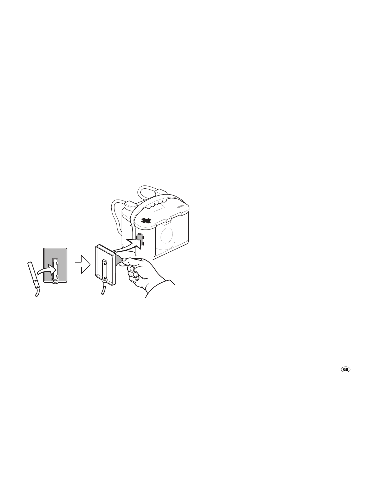
Use the enclosed Truma temperature sensor, in particular for
AGM batteries, for temperature-controlled battery charging.
Place the sensor in the centre near the positive terminal on
the housing of the battery (1). To do this, place the sensor in
the middle of the recess of the holder. Remove the protective
film from the self-adhesive holder. Press the holder firmly into
the desired position on the battery.
Temp. Sensor Fixer
TSF - 01
Fig. 3: Assembly of the temperature sensor
Connect the temperature sensor (B1) to the device (connection X1).
Cable fixing
Secure all cables (e.g. to energy sources, consumers and accessories) with cable ties.
Wiring diagram
See page 2, fig. A.
Commissioning
The device is operational as soon as a battery of a solar module is connected (observe connection sequence).
Set battery type
Set the used battery type (battery 1) (see “Query / change settings – battery type”).
Page 28
28
Veuillez impérativement lire les instructions de montage
et d’utilisation avant de brancher et de mettre en service l’appareil !
Glossaire
Batterie AGM Batterie au plomb-acide, dans
laquelle l’électrolyte se trouve dans
un mat de microfibres de verre
(absorbed glass mat).
Batterie OPTIMA® YT S Correspond à une batterie AGM.
Chargeur automatique solaire SDC 10 / 20
Mode d’emploi
Table des matières
Symboles utilisés ................................................................ 28
Mode d’emploi
Glossaire .............................................................................. 28
Informations concernant la sécurité ............................ 29
Utilisation .......................................................................... 29
Utilisation non conforme ..................................................... 30
Entretien de la batterie .................................................. 30
Éléments de l'appareil ..................................................... 30
Fonction ............................................................................. 31
Recharge ............................................................................ 31
Consultation / modification des réglages .................... 32
Utilisation ............................................................................ 32
Type de batterie ................................................................... 32
Distribution du courant de charge ..................................... 33
Fréquence de charge PWM ................................................ 33
Indicateur de fonction / diagnostic des pannes ......... 34
Entretien ............................................................................ 34
Caractéristiques techniques .......................................... 34
Diagramme de charge ........................................................ 35
Élimination ........................................................................ 35
Déclaration de garantie du fabricant
(Union européenne) ......................................................... 36
Instructions de montage
Informations concernant la sécurité ............................ 37
Fourniture .......................................................................... 38
Montage ............................................................................ 38
Branchement .................................................................... 38
Schéma des connexions ..................................................... 39
Mise en service ................................................................ 39
Symboles utilisés
Ce symbole indique des risques possibles.
Informations et conseils.
Page 29
29
Informations concernant la sécurité
Lors de l’utilisation d’appareils électriques, les
consignes de sécurité de base suivantes doivent être
respectées afin d’éviter tout risque d’électrocution, de blessure et d’incendie. Veuillez lire et respecter ces consignes
avant d’utiliser l’appareil.
Installation
Veillez à ce que les appareils soient installés de manière
sûre, ne puissent pas tomber ou se renverser. Posez toujours
les câbles de manière à éviter tout risque de trébuchement.
N’exposez pas les appareils électriques à la pluie. N’utilisez
pas les appareils électriques dans un environnement humide
ou mouillé. N’utilisez pas les appareils électriques à proximité
de liquides ou de gaz inflammables.
Protection contre les risques d’électrocution
Utilisez uniquement des appareils dont le boîtier et les câbles
sont en parfait état. Veillez à ce que les câbles soient correctement posés. Ne tirez pas sur les câbles.
Les modules solaires produisent de l’électricité sous l’incidence de la lumière. Même en cas de faible incidence de
lumière, leur tension est maximale. La tension à vide peut être
deux fois plus élevée. Ne pas toucher les pièces conductrices
d’électricité. Recouvrir les modules solaires d’un carton par
ex. avant les travaux de montage et d’installation.
Utilisation
Cet appareil n’est pas conçu pour être utilisé par des personnes (y compris des enfants) aux capacités physiques, sensorielles ou mentales réduites ou qui n’ont pas l’expérience
et/ ou les connaissances nécessaires, à moins qu’elles ne
soient surveillées par une personne responsable de leur sécurité ou qu’elles aient reçu des instructions concernant l’utilisation de l’appareil.
Les enfants doivent être surveillés afin de s’assurer qu’ils ne
jouent pas avec l’appareil.
N’utilisez pas les appareils électriques à d’autres fins que
celles indiquées par le fabricant. Les fentes d’aération du boîtier doivent être libres et ne peuvent en aucun cas être obstruées par des bagages, des serviettes ou des vêtements, etc.
Attention
Les batteries peuvent produire des gaz explosifs lors du chargement et de leur fonctionnement. Tenir les batteries éloignées des flammes et des sources d’étincelles. Veiller à une
aération suffisante du compartiment à batteries.
Réparation
N’effectuez aucune réparation ou modification sur l’appareil.
Contactez votre revendeur ou le service Truma (voir
www.truma.com).
Accessoires
Utilisez uniquement des accessoires fournis ou recommandés
par le fabricant.
Utilisation
Le chargeur automatique solaire sert à charger des accumulateurs au plomb de 12 V (24 V) composés de 6 (12) cellules
individuelles (par ex. batterie de voiture) avec une capacité de
50 – 100 Ah (SDC 10) ou 50 - 200 Ah (SDC 20). Cet appareil
a été conçu pour être raccordé à des modules solaires. Utiliser uniquement des modules adaptés, par ex. Truma SM 65,
SM100 ou SM 150. Respecter les valeurs maximales de tension et de courant absorbé. Le chargeur automatique s’utilise
de préférence avec des batteries au gel, AGM ou à électrolyte
liquide.
Cet appareil est destiné à être monté dans l’habitacle.
Page 30
30
Utilisation non conforme
L’appareil ne convient pas pour charger des
– batteries de 6 V ou des accumulateurs au plomb de 6 V,
– des batteries non rechargeables,
– des batteries au nickel-cadmium.
En cas de chargement de batteries avec une tension nominale
de 6 V à l’aide de cet appareil, le dégagement gazeux est
immédiat. Possibilité de dégagement de gaz détonant.
Cet appareil convient uniquement pour le réglage des
modules solaires. Aucune autre source de courant (par ex.
tension de secteur de 230 V) ne peut être raccordée à ‘appareil. Cela peut entraîner la destruction de l’appareil et / ou des
sources de courant. Si d’autres sources de courant doivent
être utilisées avec cet appareil, renseignez-vous auprès de
votre revendeur.
Entretien de la batterie
(également des batteries ne nécessitant aucune maintenance)
Afin de garantir une longue durée de vie des batteries, respecter les points suivants :
– les batteries doivent être entièrement rechargées avant et
après un prélèvement de courant
– en cas de période d’arrêt prolongée (sans exposition au
soleil), la batterie doit être débranchée et rechargée durant
24 heures au plus tard toutes les 12 semaines.
En hiver, conserver les batteries entièrement chargées
au frais et à l’abri du gel et les recharger régulièrement
(toutes les 12 semaines).
Éléments de l'appareil
Solar Dual Battery Charger
+–+–
2
+–
1
remote temp. sensor
remote meter connection
SET
H1 H2B2 T
H3
H4H5H6
X1 X2 X3 X4 X5
Fig. 1: éléments de l’appareil
H1 Indicateur de fonction LED de la batterie 1
(batterie d’alimentation)
H2 Indicateur de fonction LED de la batterie 2
(batterie de démarrage)
H3 Indicateur LED du type de batterie – AGM, Gel, Liquid
(électrolyte liquide)
H4 LED de distribution du courant de charge
H5 LED de fréquence de charge PWM
H6 indique les valeurs de H3, H4, H5 sous forme de chiffre
T Consultation / modification du mode de fonctionnement
B2 Sonde de température interne
X1 Raccord pour sonde de température B1
X2 Raccord pour batterie 1 (batterie d’alimentation)
X3 Raccord du module solaire
X4 Raccord batterie 2 (batterie de démarrage)
X5 Pas de fonction
Page 31

31
Fonction
L’appareil est équipé d’un système de chargement moderne,
commandé par microprocesseur, à 3 phases de modulation
d’impulsion en largeur. Cette technologie permet une puissance élevée avec un poids réduit et de faibles dimensions.
L’utilisation de pièces électroniques de qualité supérieure permet au chargeur automatique de fonctionner avec une grande
efficacité. La recharge automatique s’effectue en douceur
sans surcharge dommageable pour les batteries. La durée de
vie des batteries est ainsi sensiblement allongée. Il convient
pour les batteries avec technologie liquide, au gel ou AGM et
permet une distribution réglable du courant de charge pour
deux raccordements de batteries séparés.
Cet appareil est conçu pour le fonctionnement continu et en
parallèle. Les appareils électriques peuvent rester constamment branchés, être connectés ou déconnectés. Il alimente
les appareils en courant tout en rechargeant les batteries. La
consommation électrique doit cependant être inférieure au
courant de charge solaire, sans quoi les batteries ne seront
pas rechargées.
Lorsque l’appareil est utilisé avec une sonde de température
pour la batterie d’alimentation (batterie 1), il règle automatiquement la tension de charge en fonction de la température
de la batterie. Cela permet une recharge particulièrement
efficace et douce de la batterie. Sans sonde de température
externe, l’appareil règle le processus de chargement à l’aide
de la sonde de température interne.
Le raccordement de un ou plusieurs modules solaires permet
de recharger la batterie d’alimentation et la batterie de démarrage. Veuillez respecter les valeurs maximales de tension et
de courant absorbé.
Recharge
L’appareil dispose d’une protection électronique contre l’inversion de polarité, le courant de retour et les courts-circuits
solaires. Le courant de charge est uniquement libéré lorsque
la batterie est correctement raccordée et que la lumière du
soleil produit suffisamment de puissance (voir « Diagramme
de charge »). L’utilisation d’une sonde de température pour la
batterie d’alimentation permet de régler la recharge en fonction de la température.
Phase de charge principale
Charge avec le courant de charge solaire maximum disponible
jusqu’à ce que la tension finale de charge soit atteinte.
Phase de charge complémentaire
La tension de charge est maintenue pendant 2 heures. Une
fois ce temps écoulé, le chargeur bascule en phase de charge
de maintien.
Phase de charge de maintien
La tension de charge est réglée sur 13,8 V. Le courant de
charge baisse alors jusqu’à la valeur nécessaire à la batterie
pour compenser la décharge spontanée. Les appareils électriques continuent d’être alimentés. Lorsque la consommation
de courant dépasse le courant de charge solaire disponible, la
charge ne peut plus être assurée.
Lorsque la tension des batteries est inférieure à 13,3 V, l’appareil bascule automatiquement en phase de charge principale
– lorsque le courant de charge solaire est suffisant.
Page 32
32
Phase de charge de compensation
(Uniquement pour le type de batterie AGM et à électrolyte
liquide)
La phase de charge de compensation sert à compenser les
tensions des cellules et peut réduire les éventuels sulfatages.
Lorsque la tension de la batterie descend en dessous de
11,1V, l’appareil considère qu’il s’agit d’une décharge totale
de la batterie. L’appareil bascule en phase de compensation
durant 2 heures. Une fois ce temps écoulé, le chargeur bascule automatiquement en phase de charge de maintien.
– Les batteries totalement déchargées peuvent être
durablement endommagées. Une charge de compensation ne répare pas ces dommages.
– Les batteries à électrolyte liquide peuvent produire
des gaz explosifs, veillez à une aération suffisante. Vérifiez régulièrement le niveau de liquide.
Une surcharge peut endommager votre batterie,
vérifiez les caractéristiques techniques de votre
batterie.
– La charge de compensation augmente la tension
de charge, cela peut endommager les appareils
électriques. Veillez donc à ce que tous les appareils électriques supportent de telles tensions.
Fonctionnement en parallèle
En cas de prélèvement de courant durant le chargement des
batteries, le courant sera prélevé du courant de charge solaire
disponible. Lorsque la consommation de courant dépasse le
courant de charge disponible, l’appareil ne peut pas recharger les batteries. l’appareil commence automatiquement la
charge lorsque le courant de charge solaire disponible est à
nouveau suffisant.
Consultation / modification des réglages
Utilisation
L’affichage H6 affiche les différents réglages du système.
En poussant brièvement su la touche (T), l’appareil commute entre les LED H3, H4 et H5 ce qui s’affiche sur H6. En
poussant à nouveau sur cette touche, l’appareil repart de la
LEDH3.
Type de batterie
Le type de batterie peut uniquement être réglé pour la batterie1. Le type supposé de la batterie 2 est le même que celui
de la batterie 1.
Consultation
– Pousser sur la touche (T) jusqu’à ce que la LED H3 s’allume,
l’affichage H6 indique la valeur enregistrée.
Affichage H6 Type de batterie
1 Gel (préréglage)
2 AGM
3 Liquide (électrolyte liquide)
Modification
– Pousser sur la touche (T) durant 5 secondes jusqu’à ce que
l’affichage H6 clignote.
– Régler la valeur souhaitée en poussant sur la touche (T).
– Après 5 secondes sans actionnement de la touche, la valeur
affichée est enregistrée et le clignotement s’arrête.
Page 33
33
Distribution du courant de charge
Il est possible de régler la distribution du courant de charge
entre la batterie 1 et la batterie 2. Les distributions suivantes
peuvent être choisies.
Consultation
– Pousser sur la touche (T) jusqu’à ce que la LED H4 s’allume,
l’affichage H6 affiche la valeur enregistrée
Affichage H6 Batterie 1 Batterie 2
0 0 % 100 %
1 10 % 90 %
2 20 % 80 %
3 30 % 70 %
4 40 % 60 %
5 50 %
(préréglage)
50 %
6 60 % 40 %
7 70 % 30 %
8 80 % 20 %
9 90 % 10 %
Modification
– Pousser sur la touche (T) durant 5 secondes jusqu’à ce que
l’affichage H6 clignote.
– Régler la valeur souhaitée en poussant sur la touche (T).
– Après 5 secondes sans actionnement de la touche, la valeur
affichée est enregistrée et le clignotement s’arrête.
En cas de charge normale, l’appareil répartit le courant
de charge entre la batterie 1 et la batterie 2 en fonction
du réglage effectué. Lorsque la batterie 1 est entièrement
chargée, l’ensemble du courant de charge est attribué à la
batterie 2, indépendamment de la valeur réglée. Lorsque
la tension de la batterie 1 baisse, la charge recommence.
Lorsque seule la batterie 1 est raccordée, l’ensemble du courant de charge est attribué à cette batterie, indépendamment
du réglage effectué.
Fréquence de charge PWM
Permet de régler la fréquence d’impulsion de l’appareil. Cette
fréquence peut être modifiée afin de réduire les éventuelles
interférences.
Consultation
– Pousser sur la touche (T) jusqu’à ce que la LED H5 s’allume,
l’affichage H6 affiche la valeur enregistrée.
Affichage H6 Fréquence de charge PWM
0 25 Hz (préréglage)
1 50 Hz
2 100 Hz
– Pousser sur la touche (T) durant 5 secondes jusqu’à ce que
l’affichage H6 clignote.
– Régler la valeur souhaitée en poussant sur la touche (T).
– Après 5 secondes sans actionnement de la touche, la valeur
affichée est enregistrée et le clignotement s’arrête.
Page 34
34
Indicateur de fonction / diagnostic des
pannes
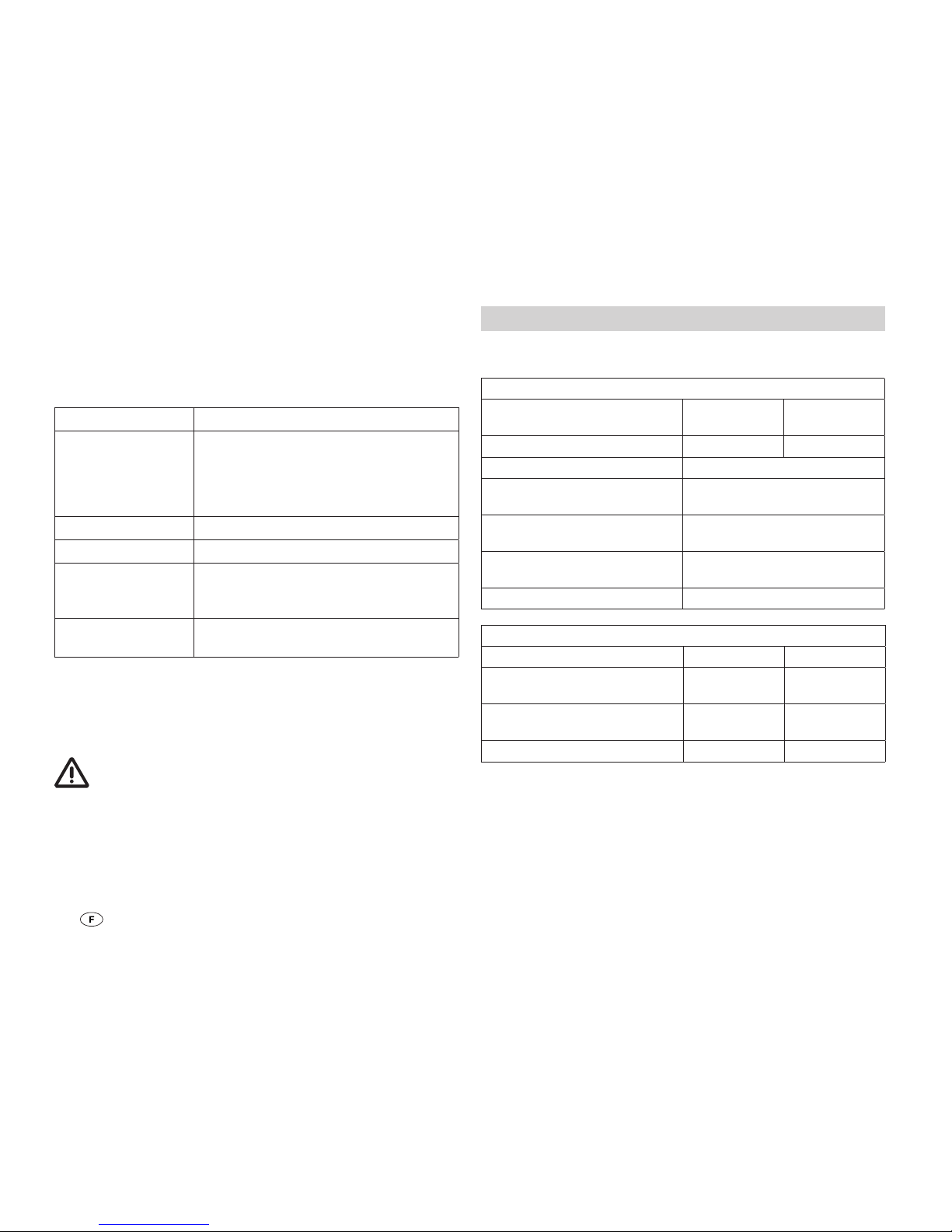
La LED H1 (H2) indique le statut de la batterie 1 (batterie 2).
Affichage Cause / dépannage
La LED émet de
flash avec de longs
intervalles
Vérifier les raccordements de l’appareil
vers la batterie et le module solaire,
veiller à la bonne polarité.
Contrôler le fusible, le module solaire
et la batterie.
La LED clignote La batterie est entièrement chargée.
La LED s’allume La batterie est en charge.
La LED émet des
flash à courts
intervalles
La batterie ne se recharge pas.
Le cas échéant, remplacer la batterie
défectueuse.
La LED ne s’allume
pas
Aucune batterie raccordée ou
surtension.
Si ces démarches ne permettent pas d’éliminer la défaillance,
adressez-vous au SAV Truma.
Entretien
Couper impérativement l’alimentation électrique de
l’appareil avant tout travail d’entretien. Recouvrir les
modules solaires à l’aide d’un carton par ex.
Nettoyez l’appareil à l’aide d’un chiffon sec sans peluches.
Caractéristiques techniques
* Indications valables pour 12 V – doubler les valeurs pour 24V.
Valeurs électriques
Tension de service
Détection automatique
12 V 24 V
Tension d’entrée max. 30 V 50 V
Plage de tension * 8 – 15 V
Plage de température am-
biante admise
-35 °C – +55 °C
Plage de température de
stockage admise
-35 °C – +80 °C
Consommation propre 4 mA la nuit,
10 mA lors de la charge
Fréquence PWM, réglable 25 Hz, 50 Hz, 100 Hz
Courants
SDC 10 SDC 20
Courant max. du module
continu à 25 °C
10 A
(env. 150 Wp)
20 A
(env. 300 Wp)
Courant de sortie max.
continu à 25 °C
10 A 20 A
Capacité de la batterie 50 – 100 Ah 50 – 200 Ah
Page 35
35
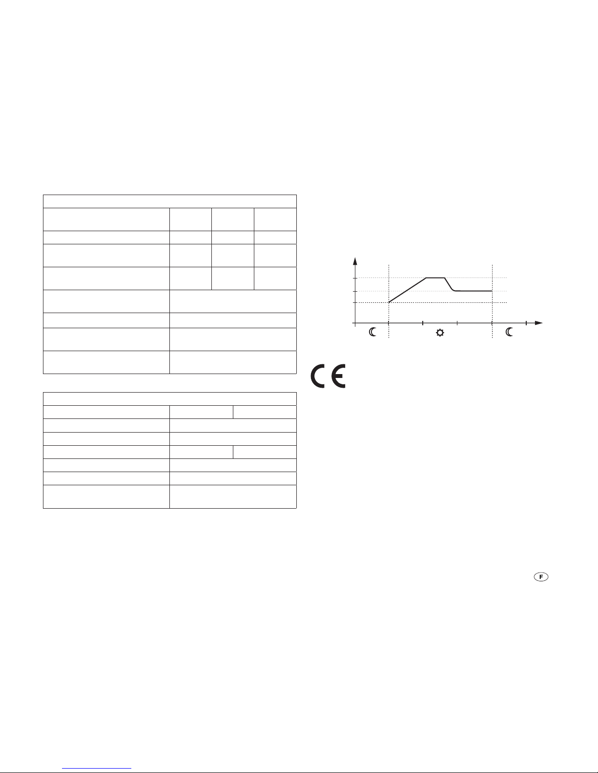
Tensions de charge
Type de batterie, réglable Gel AGM
fermée
Liquide
Phase de post-charge * 14,2 V 14,4 V 14,6 V
Phase de charge de
maintien *
13,8 V
13,8 V
13,8 V
Phase de charge de
compensation *
–
14,6 V
14,8 V
Phase de charge principale
tension de commutation *
13,3V
Tension de charge maximale * 16,6V
Compensation de
température *
-30 mV / K
Sonde de température (plage
de mesure)
-40°C – +125°C
Valeurs mécaniques
SDC 10 SDC 20
Type de protection IP 30
Montage Montage mural
Poids 200 g 230 g
Bornes de connexion 4 mm²
Dimensions L x l x H 154 x 76 x 37,5 mm
Humidité
(sans condensation)
95 %
Diagramme de charge
HL = Phase de charge principale
NL = Phase de charge complémentaire (2 heures)
EL = Phase de charge de maintien
U
EL
0
U[V]
U
NL
t[h]
ELNLHL
U
HL
Fig. 2: Diagramme de charge (déroulement de principe)
Sous réserve de modifications techniques !
Élimination
L´appareil doit être éliminé conformément aux règles administratives du pays d´utilisation. Les prescriptions et lois
nationales doivent être respectées (en Allemagne, il s´agit par
exemple du décret sur les véhicules hors d´usage).
Page 36

36
Déclaration de garantie du fabricant
(Union européenne)
1. Étendue de la garantie du fabricant
Truma, en tant que fabricant de l’appareil, accorde au consommateur une garantie couvrant les vices de l’appareil imputables
à d’éventuels défauts de matériau et/ou de fabrication.
Cette garantie s’applique dans les États membres de l’Union
européenne ainsi qu’en Islande, Norvège, Suisse et Turquie.
Le consommateur est la personne physique ayant fait l’acquisition initiale de l’appareil auprès du fabricant, d’un fabricant OEM ou d’un magasin spécialisé, sans intention de le
revendre dans le cadre d’une activité professionnelle commerciale ou indépendante, ou de l’installer chez des tiers.
La garantie couvre les vices nommés ci-dessus survenus dans
les 24 mois suivant la conclusion du contrat de vente entre le
vendeur et le consommateur. Le fabricant ou un partenaire SAV
agréé remédiera à ces défauts soit par une réparation, soit par
la livraison d’un appareil de rechange. Les pièces défectueuses
deviennent la propriété du fabricant ou du partenaire SAV
agréé. Si l’appareil n’est plus fabriqué au moment de la réclamation pour vice, le fabricant est en droit, pour la livraison d’un
appareil de rechange, de livrer un produit similaire.
Si le fabricant fournit une prestation de garantie, le délai de
garantie concernant les pièces réparées ou remplacées n’est
pas reconduit, mais l’ancien délai continue à courir jusqu’à
expiration du délai de garantie restant. Seuls le fabricant
ou un partenaire SAV agréé seront en droit de réaliser des
travaux de garantie. Les coûts liés au cas de garantie seront
réglés directement entre le partenaire SAV agréé et le fabricant. Les coûts supplémentaires dus à des difficultés de
démontage et remontage de l’appareil (par ex. démontage de
meubles ou d’éléments de carrosserie),
ainsi que les frais de déplacement du partenaire SAV agréé ou
du fabricant ne seront pas couverts par la garantie.
Toutes autres prétentions, en particulier toutes prétentions
à dommages-intérêts du consommateur ou de tiers, sont
exclues. Les dispositions de la législation allemande sur la
responsabilité du fait des produits défectueux (Produkthaftungsgesetz) restent inchangées.
Les garanties légales applicables relatives aux vices matériels
que le consommateur peut faire valoir à l’encontre du vendeur
dans le pays d’achat restent inchangées indépendamment
de la garantie volontaire du fabricant. Dans certains pays,
une garantie peut éventuellement être proposée par certains
revendeurs spécialisés (concessionnaires, partenaires Truma).
Le consommateur peut la faire valoir directement auprès du
revendeur spécialisé où il a acheté l’appareil. Les conditions
de garantie du pays où a eu lieu la première acquisition de
l’appareil par le consommateur sont applicables.
2. Exclusion de la garantie
La garantie ne s’applique pas:
– en cas d’utilisation non conforme, contraire à l’emploi prévu
pour l’appareil
– en cas d’installation, de montage ou de mise en service non
conforme suite au non-respect des instructions de montage
et du mode d’emploi
– en cas d’opération ou de manipulation non conforme suite
au non-respect des instructions de montage et du mode
d’emploi, notamment des instructions d’entretien, de maintenance et des avertissements de sécurité
– si des réparations, des installations ou des interventions ont
été exécutées par des partenaires non agréés
– pour les consommables, pièces d’usure et en cas d’usure
naturelle
– dans le cas où l’appareil est équipé de pièces de rechange,
d’équipement ou d’accessoires autres que des pièces d’origine du fabricant et qui sont à d’un défaut
Page 37
37
– en cas de dommages causés par des corps étrangers (par
ex. huiles, plastifiants dans le gaz), des réactions chimiques
ou électrochimiques dans l’eau ou si un appareil est entré
en contact avec des substances inappropriées (par ex. produits chimiques, détergents inappropriés)
– en cas de dommages causés par des conditions environne-
mentales anormales ou d’exploitation inadaptées
– en cas de dommages résultant d’un cas de force majeure
ou de catastrophes naturelles, ainsi que d’autres facteurs
qui ne sont pas imputables à Truma
– en cas de dommages causés par un transport inadapté
3. Recours en garantie
Le recours en garantie doit être formé auprès d’un partenaire SAV
agréé ou du centre de service après-vente Truma. Vous trouverez
adresses et numéros de téléphone sur www.truma.com à la
rubrique « Service ».
Afin d’assurer le bon déroulement de la garantie, prière de fournir
les informations suivantes au moment où vous prendrez contact :
– description détaillée du défaut
– numéro de série de l’appareil
– date d’achat
Le partenaire SAV agréé ou le centre de service après-vente
Truma décideront au cas par cas de la marche à suivre. Afin
de prévenir tous dommages dus au transport, l’appareil ne
devra être expédié qu’après concertation avec le partenaire
SAV agréé ou le centre de service après-vente Truma.
Si le recours en garantie est accepté par le fabricant, ce dernier prend en charge les frais de transport. Si le dommage
n’est pas couvert par la garantie, le consommateur en sera
informé et les frais de réparation et de transport seront à sa
charge. Prière de ne rien retourner sans avoir pris contact
avec nous au préalable.
Informations concernant la sécurité
Cet appareil contient des pièces qui peuvent générer
des étincelles ou un arc électrique !
Le montage et le raccordement d’appareils électriques
doivent toujours être réalisés par du personnel qualifié !
Les modules solaires produisent de l’électricité sous l’incidence de la lumière. Même en cas de faible incidence de
lumière, leur tension est maximale. La tension à vide peut être
deux fois plus élevée. Ne pas toucher les pièces conductrices
d’électricité. Recouvrir les modules solaires d’un carton par
ex. avant les travaux de montage et d’installation.
Cet appareil a été conçu pour le raccordement de modules
solaires. Utiliser uniquement des modules adaptés par ex.
Truma SM 65, SM 100 ou SM 150. Respecter les valeurs
maximales de tension et de courant absorbé.
Utilisez uniquement les diamètres de câble et les puissances
de fusible indiqués !
Ne pas installer ou utiliser l’appareil dans des locaux humides
(par ex. salles de bain) ou dans des locaux dans lesquels
des mélanges gazeux facilement inflammables peuvent se
dégager.
L’installation de l’appareil doit être conforme aux dispositions
techniques et administratives du pays d’utilisation (par ex.
EN 1648). Les prescriptions et les règlementations nationales
doivent être respectées.
Instructions de montage
Page 38
38
Fourniture
– 1 chargeur automatique solaire
– 1 sonde de température
– 1 support pour sonde de température
– 1 instructions d’utilisation et de montage
Montage
Voir page 3, fig. B, C
Installer l’appareil à l’abri de l’humidité et de l’eau. Le lieu d’installation doit être propre, sec et bien aéré. Pendant le fonctionnement, le boîtier peut atteindre une température de 80°C.
Veillez à ce que les fentes d’aération restent libres !
Une aération insuffisante peut entraîner la surchauffe
de l’appareil !
L’espace d’installation de l’appareil doit être équipé de trous
d’aération au-dessus et sur les côtés, l’ouverture totale devant
être de 100 cm².
Lorsque la température intérieure de l’appareil augmente en
raison du manque de circulation d’air ou d’une température
ambiante trop élevée, l’appareil peut être endommagé.
Les batteries à électrolyte liquide doivent être installées dans
une boîte séparée avec un système de ventilation vers l’extérieur. Une boîte séparée n’est pas nécessaire pour les batteries au gel et AGM. Respectez les consignes d’installation du
fabricant de batteries.
Fixer solidement l’appareil avec quatre vis (diamètre 4 mm–
pas de vis à tête conique). Longueur de vis et couple de serrage en fonction du support.
Branchement
Longueurs et diamètres des câbles
Réalisation conformément aux normes EN 1648-1 et
VDE0100, partie 721.
Fusibles F1, F2
SDC 10 – 15 A
SDC 20 – 30 A
Installer impérativement les fusibles à proximité de la
source d’énergie (par ex. batterie). Utiliser uniquement
les diamètres de câbles et les puissances de fusibles prescrits.
Raccordement source d’énergie / appareils électriques
Raccordez l’appareil aux modules solaires et aux batteries
conformément au schéma des connexions. Veillez à respecter
la polarité.
Branchez toujours plusieurs modules en parallèle. Utilisez
uniquement des modules avec les mêmes valeurs caractéristiques de tension (env. 18 V). Demandez le set de câbles
d’extension à votre revendeur Truma.
Respecter l’ordre de raccordement. L’adaptation auto-
matique 12 V / 24 V fonctionne uniquement correctement dans ce cas et les dommages sur la batterie peuvent
être évités.
1. Raccorder la batterie 1 (2) au régulateur de charge –
pôle positif et pôle négatif
2. Raccorder les modules solaires au régulateur de charge –
pôle positif et pôle négatif
3. Raccorder la sonde de température au régulateur de charge–
pôle positif et pôle négatif
Procéder en ordre inverse pour le démontage.
Page 39
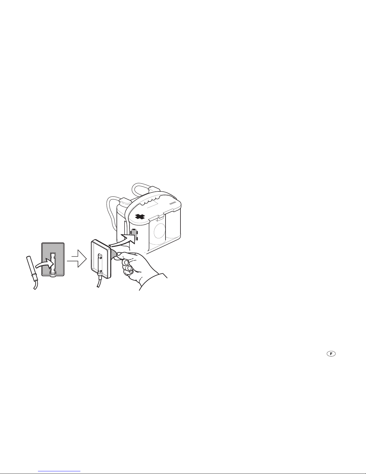
39
Sonde de température
Pour une charge de la batterie en fonction de la température,
utilisez la sonde de température Truma fournie, notamment
pour les batteries AGM.
Installer la sonde de température fournie au milieu de la zone
du pôle positif sur le boîtier de la batterie (1). Pour cela, placer
la sonde au centre de la fente du support. Retirer le filme de
protection autocollant du support. Presser fermement le support sur la batterie dans la position souhaitée.
Temp. Sensor Fixer
TSF - 01
Fig. 3: Installation de la sonde de température
Raccorder la sonde de température (B1) à l’appareil
(raccord X1).
Fixation des câbles
Fixer tous les câbles (par ex. vers les sources d’énergie, les appareils électriques et les accessoires) avec des
attache-câbles.
Schéma des connexions
Voir page 2, fig. A
Mise en service
L’appareil est en marche dès qu’une batterie ou un module
solaire sont raccordés (respecter l’ordre de raccordement).
Réglage du type de batterie
Régler le type de batterie utilisé (batterie 1) (voir « Consultation/
modification des réglages – Type de batterie »)
Page 40
40
Prima del collegamento e della messa in funzione
dell’apparecchio, leggere assolutamente le istruzioni
per il montaggio e per l’uso.
Glossario
Batteria AGM Batteria piombo-acido, nella quale
l’elettrolita è assorbito dentro una
matrice di sottili fibre di vetro (absorbed glass mat).
Batteria OPTIMA® YT S Corrisponde ad una batteria AGM.
Carica-batterie automatico solare SDC 10 / 20
Istruzioni per l’uso
Indice
Simboli utilizzati .................................................................. 40
Istruzioni per l’uso
Glossario ............................................................................. 40
Avvertenze di sicurezza .................................................. 41
Scopo d´impiego .............................................................. 41
Utilizzo non conforme alle disposizioni ............................... 42
Cura della batteria .......................................................... 42
Componenti dell'apparecchio ........................................ 42
Funzionamento ................................................................. 43
Processo di carica ............................................................ 43
Interrogazione / modifica delle impostazioni .............. 44
Comando ............................................................................. 44
Tipo di batteria ................................................................... 44
Distribuzione della corrente di carica ................................ 45
Frequenza di carica PWM ................................................... 45
Indicazione delle funzioni/Istruzioni per
la ricerca degli errori ....................................................... 46
Manutenzione ................................................................... 46
Dati tecnici ........................................................................ 46
Diagramma di carica ........................................................... 47
Smaltimento ..................................................................... 47
Dichiarazione di garanzia del produttore
(Unione Europea) .............................................................. 48
Istruzioni di montaggio
Avvertenze di sicurezza .................................................. 49
Volume di fornitura ......................................................... 50
Montaggio ......................................................................... 50
Collegamento .................................................................... 50
Schema di collegamento ................................................... 51
Messa in funzione ............................................................ 51
Simboli utilizzati
Il simbolo richiama l‘attenzione su possibili pericoli.
Indicazione con informazioni e raccomandazioni.
Page 41
41
Avvertenze di sicurezza
Durante l’utilizzo degli apparecchi elettrici è assoluta-
mente necessario osservare le seguenti misure di sicurezza fondamentali, per evitare scosse elettriche, infortuni e rischi d’incendio. Leggere e osservare queste istruzioni prima di
utilizzare l’apparecchio.
Installazione
Prestare attenzione affinché gli apparecchi vengano installati
correttamente e senza il rischio di cadute o rovesciamenti. Posare tutti i cavi in maniera tale che non sussista alcun pericolo
di inciampo. Non esporre gli apparecchi elettrici alla pioggia.
Non utilizzare gli apparecchi elettrici in ambienti umidi o
bagnati. Inoltre, non utilizzarli nelle vicinanze di liquidi o gas
infiammabili.
Protezione dalle scosse elettriche
Utilizzare soltanto apparecchi i cui alloggiamenti ed i cui cavi
siano completamente integri. Prestare attenzione alla posa
sicura dei cavi. Non tirare mai i cavi.
I moduli solari generano corrente per incidenza della luce. Anche con una bassa incidenza della luce è presente la massima
tensione. La tensione a vuoto può essere doppiamente elevata. Non toccare parti conducenti corrente. Coprire i moduli solari prima dei lavori di montaggio ed installazione, ad esempio
con un cartone.
Utilizzo
Questo apparecchio non deve essere utilizzato da persone
(compresi i bambini) con facoltà fisiche, sensoriali o psichiche limitate o prive dell’esperienza e/o della competenza
necessarie, a meno che non siano sorvegliate da una persona
preposta alla loro sicurezza o abbiano ricevuto dalla stessa
delle specifiche indicazioni su come utilizzare correttamente
l’apparecchio.
I bambini devono essere sorvegliati costantemente per assicurarsi che non giochino con l’apparecchio.
Non utilizzare gli apparecchi elettrici per scopi diversi da quelli
indicati dal produttore. Le fessure d’aerazione sull’alloggiamento devono essere libere e non devono essere coperte da
bagagli, asciugamani o vestiti, ecc.
Attenzione
Le batterie possono generare gas esplosivi durante la carica
e durante l’esercizio. Tenere lontano da fiamme e fonti d’accensione. Provvedere ad un’aerazione sufficiente del vano
batteria.
Riparazione
Non eseguire lavori di riparazione o modifiche all’apparecchio.
Rivolgersi al rivenditore di fiducia o al servizio d’assistenza
Truma (consultare il sito www.truma.com).
Accessori
Utilizzare soltanto accessori ed apparecchi supplementari forniti o raccomandati dal produttore.
Scopo d´impiego
Il carica-batterie automatico solare serve esclusivamente per
la carica di accumulatori al piombo a 12 V (24 V), costituiti da
6 (12) celle singole (ad esempio batterie per auto), con una
capacità di 50 – 100 Ah (SDC 10) ovvero 50 – 200 Ah (SDC20).
L’apparecchio è stato costruito per il collegamento di moduli
solari. Utilizzare soltanto moduli adatti, quali ad esempio
Truma SM 65, SM 100 o SM 150. Osservare i valori di tensione e di assorbimento di corrente massimi consentiti. Il
carica-batterie automatico viene preferibilmente utilizzato per
le batterie al gel, AGM o all’elettrolita liquido.
L’apparecchio è adatto al montaggio nell’abitacolo.
Page 42
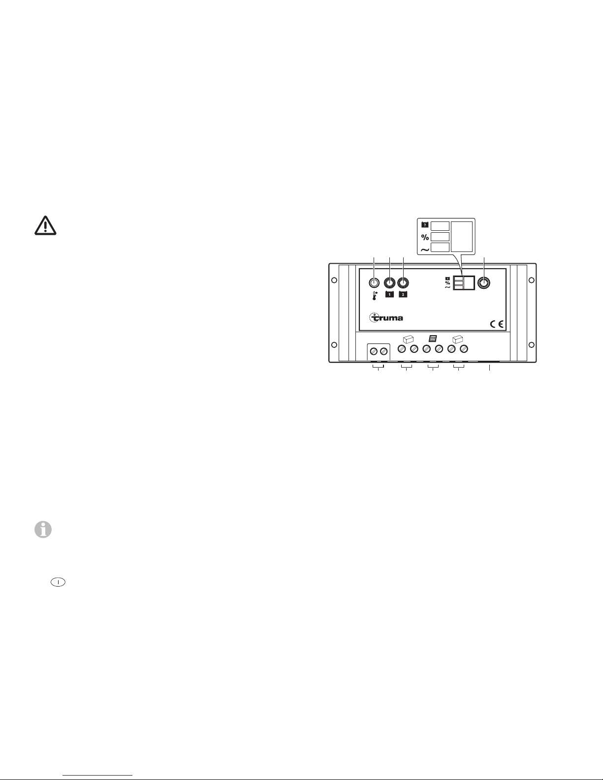
42
Utilizzo non conforme alle disposizioni
L’apparecchio non è adatto alla carica di
– batterie a 6 V o accumulatori al piombo a 6 V
– batterie non ricaricabili,
– batterie nichel-cadmio.
Se le batterie vengono caricate con questo apparecchio ad
una tensione nominale di 6 V, comincia immediatamente la
gassificazione. Può generarsi dell’ossidrogeno esplosivo.
L’apparecchio è adatto soltanto alla regolazione dei moduli
solari. Non collegare nessun’altra fonte di tensione (ad esempio tensioni di rete a 230 V) all’apparecchio. Ciò potrebbe
causare la distruzione dell’apparecchio ovvero delle fonti. Se
dovessero essere utilizzate delle altre fonti di tensione insieme
all’apparecchio, contattare prima il rivenditore.
Cura della batteria
(anche delle batterie prive di manutenzione)
Per garantire una lunga durata di vita della batteria è necessario osservare i seguenti punti:
– le batterie dovrebbero essere ricaricate completamente
prima e dopo un prelievo di corrente;
– nel caso di lunghi periodi d’inutilizzo (senza incidenza del
sole), la batteria deve essere scollegata e ricaricata al più
tardi ogni 12 settimane per 24 ore.
In inverno, stoccare le batterie completamente cariche in
un luogo fresco e protetto dal gelo e ricaricare regolar-
mente (ogni 12 settimane).
Componenti dell'apparecchio
Solar Dual Battery Charger
+–+–
2
+–
1
remote temp. sensor
remote meter connection
SET
H1 H2B2 T
H3
H4H5H6
X1 X2 X3 X4 X5
Figura 1: componenti dell’apparecchio
H1 LED indicatore del funzionamento della batteria 1
(batteria di alimentazione)
H2 LED indicatore del funzionamento della batteria 2
(batteria di avviamento)
H3 LED del tipo di batteria: AGM, gel, liquido
(elettrolita liquido)
H4 LED di distribuzione della corrente di carica
H5 LED della frequenza di carica PWM
H6 Indicazione dei valori di H3, H4, H5 in forma numerica
T Interrogazione / modifica della modalità d’esercizio
B2 Sensore temperatura interno
X1 Collegamento del sensore temperatura B1
X2 Collegamento della batteria 1 (batteria di alimentazione)
X3 Collegamento del modulo solare
X4 Collegamento della batteria 2 (batteria di avviamento)
X5 Senza funzione
Page 43

43
Funzionamento
L’apparecchio è dotato di una moderna tecnologia di carica a
tre fasi, modulata a larghezza di impulso e gestita da un microprocessore. Questa tecnica consente altissime prestazioni
nonostante il peso minimo e le misure ridotte. Grazie all’utilizzo di una centralina elettronica di alta qualità, l’apparecchio
funziona con un elevato grado di rendimento. La carica automatica avviene delicatamente senza sovraccarico dannoso
delle batterie. In questo modo si garantisce un essenziale
prolungamento di durata di vita della batteria stessa. È adatto
alle batterie con tecnologia a liquido, gel o AGM ed offre una
distribuzione della corrente di carica impostabile per due collegamenti separati delle batterie.
L’apparecchio è stato concepito per un funzionamento continuo e in parallelo. Le utenze possono restare collegate ininterrottamente, venire collegate o scollegate. In contemporanea
vengono alimentate le utenze e viene caricata la batteria. Al
riguardo, la corrente di consumo deve essere minore rispetto
alla corrente di carica solare, altrimenti non ha luogo la carica
della batteria.
Se l’apparecchio viene fatto funzionare insieme ad un sensore
temperatura esterno per la batteria di alimentazione (batteria1),
l’apparecchio regola la tensione di carica in automatico in
base alla temperatura della batteria. In questo modo si ottiene
una carica della batteria particolarmente efficace e delicata.
Senza l’utilizzo di un sensore temperatura esterno, l’apparecchio regola il processo di carica in base ad un sensore temperatura interno.
Collegando uno o più moduli solari è possibile caricare la
batteria di alimentazione e la batteria di avviamento. A tale
proposito, osservare i valori di tensione e di assorbimento di
corrente massimi consentiti.
Processo di carica
L’apparecchio è dotato di una protezione elettronica contro
l’inversione della polarità, contro la corrente inversa e contro
il cortocircuito solare. Solo se la batteria è correttamente
collegata ed è a disposizione una potenza sufficiente dalla
luce solare si abilita la corrente di carica (vedere «Diagramma
di carica»). Se si utilizza un sensore temperatura per la batteria di alimentazione, il processo di carica dipenderà dalla
temperatura.
Fase principale di carica
Carica con la corrente di carica solare massima disponibile
fino al raggiungimento della tensione di carica finale.
Fase di ricarica
La tensione di carica viene mantenuta per una durata di 2 ore.
Allo scadere di questo tempo ha luogo la commutazione in
fase di carica di mantenimento.
Fase di mantenimento della carica
La tensione di carica è impostata su 13,8 V. La corrente di
carica si riduce fino al valore necessario per la compensazione
dell’auto-scaricamento della batteria. Le utenze continuano ad
essere alimentate. Se la corrente consumata supera la corrente di carica solare disponibile, non è più possibile mantenere
correttamente la carica.
Se la tensione della batteria scende al di sotto di 13,3 V – in
presenza di sufficiente corrente di carica solare – l’apparecchio passa automaticamente in fase principale di carica.
Page 44
44
Fase di carica di compensazione
(Solo per i tipi di batteria AGM e ad elettrolita liquido)
La fase di carica di compensazione serve per la compensazione delle tensioni delle celle e può ridurre le solfatazioni
presenti.
Se la tensione della batteria scende al di sotto di 11,1 V, si
presume lo scaricamento completo della batteria. L’apparecchio passa per 2 ore nella fase di carica di compensazione.
Allo scadere delle due ore passa automaticamente nella fase
di mantenimento delle carica.
– Le batterie completamente scariche potrebbero
danneggiarsi durevolmente e la carica di compensazione non è in grado di porre rimedio.
– Con le batterie ad elettrolita liquido possono ge-
nerarsi gas esplosivi; pertanto, provvedere ad una
sufficiente ventilazione. Controllare regolarmente
il livello del liquido. Un sovraccarico può danneggiare la vostra batteria; controllare pertanto i dati
relativi alla batteria.
– La carica di compensazione aumenta la tensione
di carica e ciò potrebbe danneggiare le utenze.
Assicurare che tutte le utenze siano adeguate a
queste tensioni.
Funzionamento in parallelo
Se, durante la carica della batteria, si preleva corrente per le
utenze, questa viene rifornita dalla corrente di carica solare
disponibile. Se il consumo di corrente supera la corrente di
carica solare disponibile, l’apparecchio non può caricare la
batteria. L’apparecchio inizia in automatico con la carica se è
nuovamente disponibile sufficiente corrente di carica solare.
Interrogazione / modifica delle
impostazioni
Comando
L’indicatore H6 indica le diverse impostazioni del sistema. Premendo brevemente il tasto (T) avvengono la commutazione
tra i LED H3, H4 e H5 e l’indicazione in H6. Premendo nuovamente il tasto si ricomincia dal LED H3.
Tipo di batteria
Il tipo di batteria può essere impostato solo per la batteria 1,
mentre la batteria 2 viene acquisita come batteria dello stesso tipo.
Interrogazioni
– Premere il tasto (T) fino a che si illumina il LED H3; nell’indi-
catore H6 viene indicato il valore salvato.
Indicatore H6 Tipo di batteria
1 Gel (pre-impostazione)
2 AGM
3 Liquido (ad elettrolita liquido)
Modifica
– Premere il tasto (T) per 5 secondi, fino a che l’indicatore H6
lampeggia.
– Premendo il tasto (T), impostare il valore desiderato.
– Dopo 5 secondi senza la pressione di alcun tasto viene
salvato il valore indicato ed il lampeggio si interrompe.
Page 45
45
Distribuzione della corrente di carica
È possibile impostare la distribuzione della corrente di carica
tra la batteria 1 e la batteria 2. Sono selezionabili le seguenti
distribuzioni.
Interrogazioni
– Premere il tasto (T) fino a che si illumina il LED H4; nell’indi-
catore H6 viene indicato il valore salvato.
Indicatore H6 Batteria 1 Batteria 2
0 0 % 100 %
1 10 % 90 %
2 20 % 80 %
3 30 % 70 %
4 40 % 60 %
5 50 %
(pre-impostazione)
50 %
6 60 % 40 %
7 70 % 30 %
8 80 % 20 %
9 90 % 10 %
Modifica
– Premere il tasto (T) per 5 secondi, fino a che l’indicatore H6
lampeggia.
– Premendo il tasto (T), impostare il valore desiderato.
– Dopo 5 secondi senza la pressione di alcun tasto viene
salvato il valore indicato ed il lampeggio si interrompe.
Durante il normale processo di carica, l’apparecchio
distribuisce la corrente di carica tra la batteria 1 e la batteria 2 così come impostato. Se la batteria 1 è completamente
carica, l’intera corrente di carica viene condotta nella batteria2, indipendentemente dal valore impostato. Se si riduce la
tensione della batteria 1, ricomincia il processo di carica. Se è
collegata soltanto la batteria 1, tutta la corrente di carica viene
condotta in questa batteria, indipendentemente dal valore
impostato.
Frequenza di carica PWM
Con questa è possibile impostare la frequenza d’impulso
dell’apparecchio. Questa può essere modificata per la riduzione di eventuali interferenze.
Interrogazioni
– Premere il tasto (T) fino a che si illumina il LED H5; nell’indi-
catore H6 viene indicato il valore salvato.
Indicatore H6 Frequenza di carica PWM
0 25 Hz (pre-impostazione)
1 50 Hz
2 100 Hz
– Premere il tasto (T) per 5 secondi, fino a che l’indicatore H6
lampeggia.
– Premendo il tasto (T), impostare il valore desiderato.
– Dopo 5 secondi senza la pressione di alcun tasto viene
salvato il valore indicato ed il lampeggio si interrompe.
Page 46
46
Indicazione delle funzioni/Istruzioni per
la ricerca degli errori
Il LED H1 (H2) indica lo stato della batteria 1 (batteria 2).
Indicazione Causa / Rimozione
Il LED lampeggia a
lunghi intervalli di
tempo
Controllare tutti i collegamenti dall’apparecchio alla batteria ed al modulo
solare, prestando attenzione alla corretta polarità.
Controllare i fusibili, il modulo solare e
la batteria.
Il LED lampeggia La batteria è stata caricata
completamente.
Il LED si accende La batteria viene caricata.
Il LED lampeggia
a brevi intervalli di
tempo
La batteria non viene caricata.
Sostituire la batteria eventualmente
guasta.
Il LED non si
accende
Nessuna batteria collegata o
sovratensione.
Se questi rimedi non dovessere funzionare per eliminare i disturbi, rivolgetevi al servizio assistenza di Truma.
Manutenzione
Prima di tutti i lavori di manutenzione all’apparecchio,
disinserire assolutamente l’alimentazione elettrica.
Coprire i moduli solari, ad esempio con un cartone.
Pulire l’apparecchio con un panno asciutto e privo di lanugine.
Dati tecnici
* Per i valori a 24 V, raddoppiare le indicazioni per i 12 V.
Valori elettrici
Tensione d’esercizio
identificazione automatica
12 V 24 V
Tensione di ingresso
massima
30 V 50 V
Gamma di tensione * 8 – 15 V
Gamma di temperatura
ambiente consentita
-35 °C – +55 °C
Gamma temperatura di
stoccaggio consentita
-35 °C – +80 °C
Consumo proprio 4 mA di notte,
10 mA durante la carica
Frequenza PWM,
impostabile
25 Hz, 50 Hz, 100 Hz
Correnti
SDC 10 SDC 20
Corrente del modulo
massima, costante a 25 °C
10 A
(circa
150 Wp)
20 A
(circa
300 Wp)
Corrente di uscita massima,
costante a 25 °C
10 A 20 A
Capacità della batteria 50 – 100 Ah 50 – 200 Ah
Page 47
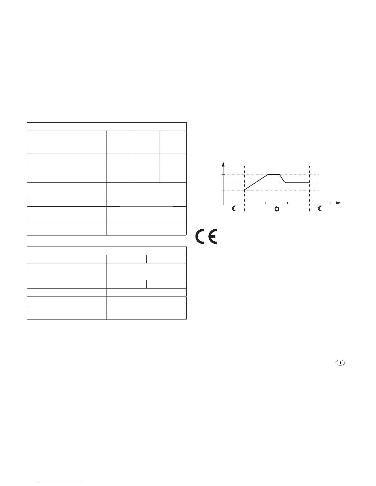
47
Tensioni di carica
Tipo di batteria, impostabile Gel AGM
chiusa
Flüssig
Fase di carica successiva * 14,2 V 14,4 V 14,6 V
Fase di carica di
mantenimento *
13,8 V
13,8 V
13,8 V
Fase di carica di
compensazione *
–
14,6 V
14,8 V
Tensione di commutazione
fase di carica principale *
13,3V
Tensione di carica massima * 16,6V
Compensazione della
temperatura *
-30 mV / K
Sensore temperatura
(gamma di misura)
-40°C – +125°C
Valori meccanici
SDC 10 SDC 20
Tipo di protezione IP 30
Montaggio Montaggio a parete
Peso 200 g 230 g
Morsetti 4 mm²
Misure (Lu x La x Al) 154 x 76 x 37,5 mm
Umidità
(non condensante)
95 %
Diagramma di carica
HL = Fase principale di carica
NL = Fase di ricarcia (2 ore)
EL = Fase di mantenimento della carica
U
EL
0
U[V]
U
NL
t[h]
ELNLHL
U
HL
Figura 2: diagramma di carica (andamento principale)
Il produttore si riserva la facoltà di apportare modifiche
tecniche!
Smaltimento
L´apparecchio deve essere smaltito secondo le disposizioni
amministrative del rispettivo paese d´utilizzo. Rispettare le leggi e le normative nazionali (in Germania, ad esempio, la legge
sulla rottamazione di veicoli usati).
Page 48

48
Dichiarazione di garanzia del produttore
(Unione Europea)
1. Ambito di validità della garanzia del produttore
Truma, in quanto produttore dell’apparecchio, concede al consumatore una garanzia a copertura di eventuali vizi del materiale e/o di fabbricazione.
Questa garanzia vale negli Stati membri dell’Unione Europea
nonché in Islanda, Norvegia, Svizzera e Turchia. Il consumatore è la persona fisica, che per prima ha acquistato l’apparecchio dal produttore, OEM o rivenditore specializzato, e che
non lo rivende nell’ambito di un’attività commerciale o professionale autonoma né lo installa presso terzi.
La garanzia del produttore si applica ai vizi summenzionati,
che si manifestano entro 24 mesi dalla conclusione del contratto di acquisto tra il venditore e il consumatore. Il produttore o un partner di assistenza autorizzato provvederà all’eliminazione di tali vizi mediante adempimento successivo, ovvero
mediante riparazione o sostituzione a propria discrezione. Le
parti difettose diventeranno di proprietà del produttore o del
partner di assistenza autorizzato. Qualora al momento della
denuncia del vizio l’apparecchio risulti fuori produzione, in caso di fornitura sostitutiva il produttore potrà fornire anche un
prodotto simile.
Nel caso in cui il produttore decida di prestare garanzia, il
periodo di garanzia relativo ai pezzi riparati o sostituiti non
decorrerà ex-novo, ma terminerà in base al vecchio periodo di
garanzia. Sono autorizzati a svolgere i lavori in garanzia esclusivamente il produttore o un partner di assistenza autorizzato.
I costi derivanti dalla garanzia saranno conteggiati direttamente tra il partner di assistenza autorizzato e il produttore. Ulteriori costi derivanti da condizioni di smontaggio e montaggio
dell’apparecchio più gravose (ad es. smontaggio di parti di
mobili o carrozzeria) nonché le spese di trasferta del partner
di assistenza autorizzato o del produttore non possono essere
riconosciuti in garanzia.
Si escludono ulteriori pretese, in particolare richieste di risarcimento dei danni da parte del consumatore o di terzi. Restano
salve le disposizioni della legge sulla responsabilità del produttore (Produkthaftungsgesetz).
Con la garanzia volontaria del produttore restano comunque
invariati i diritti di legge del consumatore derivanti dai vizi della
cosa vigenti nei confronti del venditore nel paese di acquisto.
In singoli paesi possono sussistere garanzie che vengono rilasciate dai rivenditori specializzati (concessionari, rivenditori
autorizzati, Truma Partner). Il consumatore può avvalersene
direttamente tramite il rivenditore specializzato presso il quale
ha effettuato l’acquisto dell’apparecchio. Si applicano le condizioni di garanzia del paese in cui il consumatore ha effettuato il primo acquisto dell’apparecchio.
2. Esclusione della garanzia
La garanzia è esclusa:
– in seguito all’utilizzo scorretto non conforme all’utilizzo
previsto
– in seguito a installazione, montaggio o messa in funzione
scorretti non conformi alle istruzioni per l’uso e di montaggio
– in seguito a funzionamento o uso scorretto non conforme
alle istruzioni per l’uso e di montaggio, in particolare in caso
di inosservanza delle istruzioni di manutenzione e cura e
delle avvertenze
– se riparazioni, installazioni o interventi vengono effettuati da
partner non autorizzati
– per materiali di consumo, componenti soggetti ad usura e
naturale logoramento
– se l’apparecchio viene dotato di ricambi, parti integrative o
accessori non originali del produttore causando in tal modo
un difetto
Page 49
49
– in seguito a danni dovuti a sostanze estranee (ad es. oli,
plastificanti nel gas), influssi chimici o elettrochimici nell’acqua o se l’apparecchio entra altrimenti in contatto con
sostanze inappropriate (ad es. prodotti chimici, detergenti
inappropriati)
– in seguito a danni dovuti a condizioni ambientali anomale o
in caso di condizioni operative inappropriate
– in seguito a danni dovuti a forza maggiore o catastrofi natu-
rali, nonché ad altre cause non imputabili a Truma
– in seguito a danni riconducibili al trasporto scorretto
3. Esercizio del diritto di garanzia
Il diritto di garanzia deve essere esercitato presso un partner
di assistenza autorizzato o il centro di assistenza Truma. Tutti
gli indirizzi e i numeri di telefono sono disponibili sul sito
www.truma.com nella sezione «Service».
Per consentire lo svolgimento regolare, si prega di tenere a
portata di mano le seguenti informazioni prima di contattare
l’assistenza:
– descrizione dettagliata del difetto
– numero di matricola dell’apparecchio
– data d’acquisto
Il partner di assistenza autorizzato o il centro di assistenza
Truma stabiliranno le ulteriori modalità di procedura. Per evitare eventuali danni dovuti al trasporto, l’apparecchio in questione può essere inviato solo previo accordo con il partner di
assistenza autorizzato o il centro di assistenza Truma.
Se la garanzia viene accettata dal produttore, questi si farà carico dei costi di trasporto. Qualora il caso non sia coperto dalla
garanzia, il consumatore ne sarà informato e i costi di riparazione e di trasporto saranno a suo carico. Si prega di astenersi
dall’effettuare spedizioni prima di aver preso i relativi accordi.
Avvertenze di sicurezza
In questo apparecchio sono contenute componenti che
potrebbero generare scintille o archi voltaici!
Il montaggio ed il collegamento degli apparecchi elettrici deve
essere effettuato esclusivamente da personale specializzato
idoneo!
I moduli solari generano corrente per incidenza della luce. Anche con una bassa incidenza della luce è presente la massima
tensione. La tensione a vuoto può essere doppiamente elevata. Non toccare parti conducenti corrente. Coprire i moduli solari prima dei lavori di montaggio ed installazione, ad esempio
con un cartone.
L’apparecchio è stato costruito per il collegamento di moduli
solari. Utilizzare soltanto moduli adeguati, ad esempio Truma
SM 65, SM 100 o SM 150. A tale proposito, osservare i valori
di tensione e di assorbimento di corrente massimi consentiti.
Utilizzare soltanto le sezioni dei cavi e le dimensioni dei fusibili
prescritte!
Non installare o azionare l’apparecchio in ambienti umidi (ad
esempio nei bagni) o in spazi dove potrebbero generarsi miscele di gas facilmente infiammabili.
Il montaggio dell’apparecchio deve essere conforme alle
disposizioni tecniche e amministrative del rispettivo paese
d’utilizzo (ad esempio: EN 1648). Osservare le disposizioni e
normative nazionali.
Istruzioni di montaggio
Page 50
50
Volume di fornitura
– 1 Carica-batterie automatico solare
– 1 Sensore temperatura
– 1 Supporto per sensore temperatura
– 1 Istruzioni per l’uso ed il montaggio
Montaggio
Vedere pagina 3, figure B e C
L’apparecchio deve essere installato in ambienti protetti dall’umidità e l’acqua. Inoltre, il luogo dell’installazione deve essere
pulito, asciutto e ben areato. Durante il funzionamento, l’alloggiamento può surriscaldarsi fino a circa 80 °C.
Prestare attenzione affinché le feritoie di ventilazione siano libere! Un’aerazione insufficiente può provocare un
surriscaldamento dell’apparecchio!
L’area d’installazione dell’apparecchio deve essere provvista
di feritoie di ventilazione superiori e laterali, che garantiscano
un’apertura complessiva di 100 cm².
Se la temperatura all’interno dell’apparecchio aumentasse,
a causa di una circolazione insufficiente dell’aria o di una
temperatura ambiente troppo alta, l’apparecchio potrebbe
danneggiarsi.
Le batterie con elettrolita liquido devono essere sistemate in una
scatola separata con ventilazione verso l’esterno. Per le batterie
al gel e AGM non è necessaria una scatola separata. Osservare
le disposizioni d’installazione del produttore della batteria.
Fissare l’apparecchio con quattro viti (diametro 4 mm – non
utilizzare viti a testa svasata). La lunghezza delle viti ed il momento torcente dipendono dal sottofondo.
Collegamento
Lunghezze e sezioni dei cavi
Esecuzione a norma EN 1648-1 e VDE 0100, Parte 721.
Fusibili F1, F2
SDC 10 – 15 A
SDC 20 – 30 A
Applicare i fusibili assolutamente vicino alla fonte d’energia (ad esempio la batteria). Utilizzare soltanto le
sezioni dei cavi e le dimensioni dei fusibili prescritte!
Collegamento della fonte di energia / dell’utenza
Collegare l’apparecchio ai moduli solari e alle batterie secondo lo schema di collegamento. Prestare attenzione al corretto
collegamento dei poli.
Collegare più moduli solari sempre in parallelo. A tale proposito, utilizzare solo moduli con gli stessi valori di tensione tipica
(circa 18 V). Richiedete presso il vostro rivenditore la prolunga
del set cavi di Truma.
Osservare la sequenza di collegamento. L’adattamento
automatico 12 V / 24 V funziona correttamente solo
in questo modo; inoltre, così si possono evitare danni alla
batteria.
1. Collegare la batteria 1 (2) al regolatore di carica – positivo e
negativo
2. Collegare i moduli solari al regolatore di carica – positivo e
negativo
3. Collegare il sensore temperatura al regolatore di carica –
positivo e negativo
Per lo smontaggio procedere con la sequenza inversa.
Page 51
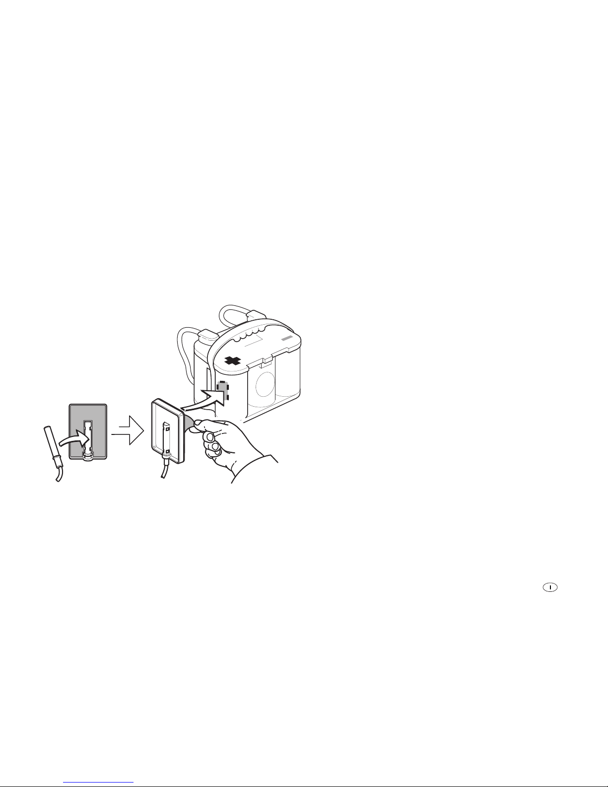
51
Sensore temperatura
Per il caricamento della batteria a temperatura controllata utilizzare il sensore temperatura Truma fornito, soprattutto per le
batterie AGM.
Applicare il sensore al centro dell’area del polo positivo sull’alloggiamento della batteria (1). A tale fine, posizionare il sensore al centro nella fessura del supporto. Rimuovere la pellicola
protettiva del supporto autoadesivo. Premere con forza il supporto nella posizione desiderata sulla batteria.
Temp. Sensor Fixer
TSF - 01
Figura 3: montaggio del sensore temperatura
Collegare il sensore temperatura (B1) all’apparecchio (collegamento X1)
Fissaggio dei cavi
Assicurare tutti i cavi (ad esempio verso fonti d’energia, utenze ed accessori) con fascette serracavi.
Schema di collegamento
Vedere pagina 2, figura A
Messa in funzione
L'apparecchio è in funzione non appena avviene il collegamento di una batteria o di un modulo solare (osservare la sequenza di collegamento).
Impostazione del tipo di batteria
Impostare il tipo di batteria utilizzato (batteria 1) (vedere
«Interrogazione / modifica delle impostazioni – Tipo di
batteria»).
Page 52

Truma Gerätetechnik GmbH & Co. KG
Wernher-von-Braun-Straße 12
85640 Putzbrunn
Deutschland
Service
Telefon +49 (0)89-4617-2020
Telefax +49 (0)89 4617-2159
[email protected]
www.truma.com
76000-31500 · 05 · 03/2017 ©
Bei Störungen wenden Sie sich bitte an das Truma
Servicezentrum oder an einen unserer autorisierten
Servicepartner (siehe www.truma.com).
Für eine rasche Bearbeitung halten Sie bitte Gerätetyp und
Seriennummer (siehe Typenschild) bereit.
Should problems occur, please contact the Truma Service
Centre or one of our authorised service partners
(see www.truma.com).
In order to avoid delays, please have the unit model and serial
number ready (see type plate).
Veuillez vous adresser au centre de SAV Truma ou à un de
nos partenaires de SAV agréés en cas de dysfonctionnements
(voir www.truma.com).
Pour un traitement rapide de votre demande, veuillez tenir
prêts le type d’appareil et le numéro de série (voir plaque
signalétique).
In caso di guasti rivolgersi al centro di assistenza Truma o a
un nostro partner di assistenza autorizzato (consultare il sito
www.truma.com).
Affinché la richiesta possa essere elaborata rapidamente,
tenere a portata di mano il modello dell’apparecchio e il
numero di matricola (vedere targa dati).
Las instrucciones de uso y montaje en su idioma
pueden ser solicitadas al fabricante Truma o al
servicio Truma de su país.
 Loading...