

Page 1

13
Mover SE R / TE R
Safety instructions
– The SE R / TE R control systems may only be used for the
Mover SE R / TE R.
– Practice operating the Mover in an open area before using
for the first time. This to fully familiarise yourself with
the handset / mover operation.
– Always check tyres and drive rollers before using the equip-
ment; remove sharp-edged stones and the like if necessary.
– No person must be present in the caravan during operation.
– All persons (particularly children) must remain outside
the Mover operating area.
– When operating the mover, ensure that no hairs, fingers or
other body parts, clothing or any other objects carried on
the body can become trapped by moving or rotating parts
(e.g. drive rollers).
– The distance between the radio remote hand set and the
centre of the caravan when manoeuvring must not
exceed 10 m!
– In the event of malfunctions pull on the handbrake.
– To prevent the caravan from tipping, direct the tow hitch
downhill when manoeuvering down a slope.
– After manoeuvring, always apply the handbrake first, dis-
engage the drive rollers from the tyres and block the
wheels (particularly on downwards-sloping surfaces). The
Mover is not suitable for use as a parking brake for a
parked caravan.
– Ensure that remote radio control is protected from unau-
thorised access (particularly by children!).
– Never tow the caravan with the drive rollers applied. This
can cause damage to the tyres, the towing vehicle and the
drive units.
– All wheels and tyres on the caravan must be of the same
size and design.
– In order to ensure that the Mover operates correctly, the
distance between the tyres and the disengaged drive rollers
must be 20 mm. All tyres must have the same inflation pressure as per the manufacturer’s instructions (check at regular intervals!). If tyres are worn or new tyres are fitted, the
distance between the drive rollers and the tyres may need
readjusting (see “Installation of the drive units”).
– Do not use the Mover as a support when jacking up the
caravan, since this can damage the drive unit.
– Sensitive objects such as cameras, DVD-Players etc. must
not be kept in the stowage box near the control unit or the
motor cable. They can be damaged by the electromagnetic
fields.
– The empty weight of the vehicle increases by the weight of
the Movers, which reduces the payload of the vehicle.
– Remove plug from safety socket after manoeuvring, other-
wise the battery will be discharged. Standby current with
plug inserted approx. 200 mA. Standby current with plug
removed < 1 mA.
General instructions
The Mover SE R was developed for overcoming inclines of
up to approx. 25 % with a gross weight of 1200 kg and 15 %
with a gross weight of 2000 kg,
and the Mover TE R for overcoming inclines of up to approx.
25 % with a gross weight of 1200 kg and 10 % with a gross
weight of 2250 kg on a suitable surface.
Depending on the weight of the caravan, the Mover cannot
overcome obstructions that are more than about 3 cm in
height without assistance (please use wedges as a ramp).
Due to the nature of a radio signal, it can get corrupted by external terrain or objects. So there may be small areas around
the caravan where the quality of reception reduces, hence the
Mover may stop momentarily.
When the Mover is switched off using the remote control
the control unit remains in standby. In order to switch off
completely the battery must be disconnected or an isolating
switch installed.
Batteries
We recommend the use of so-called drive and lighting batteries.
Gel batteries and round cell batteries are also suitable.
These batteries are designed for high power demands and
have an extremely long service life. The maximum power
consumption of the Mover on the steepest incline and carrying the maximum weight is 150 A. The correct choice of battery depends on the usage period and the scope of use (other
consumers in caravan). For mover operation we recommend
batteries with a capacity of approx. 80 Ah or more.
Example:
A fully charged lead-acid battery with a capacity of 80 Ah allows the Mover to be operated for approximately 30 minutes
with a full load (depending on weight of caravan, battery type
and terrain). On level terrain the Mover has average power
consumption of approximately 35 A and therefore an operating time of approx. 2 hours.
The use of gel batteries or round cell batteries means that
smaller batteries can be used.
Batteries with more capacity allow the equipment to be used
for longer.
For optimum operation, we recommend the Truma Mover
PowerSet.
Function description
Always observe the operating instructions and “Safety
instructions” prior to starting! The vehicle owner is respon-
sible for correct operation of the appliance.
Please note that the Mover SE R is only suitable for
single-axle towed vehicles, and the Mover TE R is only
suitable for dual-axle towed vehicles.
The Mover is a manoeuvring system with which a caravan can
be moved without the assistance of a towing vehicle.
It consists of two separate drive units, each of which has a
12 Volt DC motor. These units are attached to the frame of the
vehicle near the wheels and are connected by lateral bars.
Once the drive rollers have been engaged to the tyres using
the remote hand set, the Mover is ready for operation. All operation takes place using the remote hand set. This transmits
radio signals to the control unit. A separate 12 V lead-acid
battery or suitable lead-gel battery (not included in scope of
delivery) supplies the control unit with current.
Page 2

14
Operating instructions
Remote handset
a = On / Off slide switch
I On (green LED illuminates)
£ Off (green LED goes off)
b = Caravan forwards (both wheels
rotate in forwards direction)
c = Caravan reverse (both wheels
rotate in reverse direction)
d = Caravan right forwards
(left wheel rotates in forwards
direction)
e = Caravan left forwards
(right wheel rotates in forwards
direction)
f = Caravan right reverse (left wheel
rotates in reverse direction)
g = Caravan left reverse (right wheel
rotates in reverse direction)
Mover SE R only
The caravan can be turned in a circle on the spot without
moving forward.
d + g = Turn caravan to the right
(left wheel rotates forwards + right wheel rotates
backwards)
e + f = Turn caravan to the left
(left wheel rotates backwards + right wheel rotates
forwards)
Mover TE R only
Turning on the spot without moving forward is not possible
because of the two axles. Pressing the d, g, e or f buttons
causes the Mover to move in a circle, whereby the outer
motor runs continuously and the inner motor pulsates.
Mover SE R / TE R
h = Two-hand operation, engage drive rollers
i = Two-hand operation, disengage drive rollers
Both buttons must always be pressed simultaneously to
engage or disengage the drive rollers.
The engaging or disengaging starts after about 3 seconds
(safety delay). The drive rollers automatically move to the end
position, even if both buttons are released.
Pressing the two buttons for disengaging whilst the
Mover is engaging in causes the engaging procedure to
be aborted. The drive rollers will disengage and automatically
move to the end position.
The remote hand set switches off:
– after approx. 2 minutes, if no button is pressed
– after approx. 7 minutes, if one of the movement buttons is
permanently held down. The green LED goes off.
To reactivate the remote control, move slide switch to “Off“ £
and then back to “On“ I
after approximately 1 second.
There is no “On / Off“ switch on the caravan to be operated.
Remote hand set LED flash codes and
acoustic signal
LED “On“ and no acoustic signal
System is ready for operation
LED “Off” and no acoustic signal
System off
(check remote hand set batteries if necessary)
LED “flashes” in combination with acoustic signal
– for approx. 5 seconds after switching the remote hand set
on, until the system is ready for operation.
– for approx. 10 seconds after switching the remote hand set
on, then it is switched off again – 13-pin safety plug not
connected to safety socket or unable to establish radio link
to controller.
– every 3 seconds if the caravan battery has a low charge
(finish manoeuvring as quickly as possible and charge
battery).
– 5 times a second (5 Hz) if the caravan battery voltage is
low. No manoeuvring is possible until the battery voltage is
above 11 V again (e.g. by means of recovery / battery charging). The drive rollers can also be disengaged with a voltage
of less than 11 V.
– approx. 2 times per second with overcurrent / over-
temperature (2 Hz). Switch remote hand set off and on
again (wait for cooling down if necessary in the event of
overtemperature).
Changing the batteries in the remote handset
Please be sure to use leak proof microbatteries only, type LR 03, AAA, AM 4,
MN 2400 (1.5 V).
When fitting new batteries
ensure the polarity is correct!
Dead and used batteries may
leak and damage the remote
handset! Remove the batteries if the
handset is not going to be used for an
extended period.
No claims under guarantee will be considered for damage
caused by leaking batteries.
Before throwing away a defective handset, it is essential that
the batteries are removed and disposed of in proper manner.
Page 3

15
Manoeuvring the caravan
Please read the “Safety instructions” before using
the Mover!
Apply handbrake with caravan uncoupled.
Unplug 13-pin plug from vehicle and plug into safety socket of
caravan.
For safety reasons the Mover can only be operated if the
13-pin plug of the caravan has been plugged into the
safety socket.
If there is a fault in both caravan brake lights, the power
circuit of the safety socket is not closed. In this case the
Mover cannot be operated.
Switch remote hand set on – green LED flashes for 5 seconds
in combination with the acoustic alarm until the control unit is
ready for operation.
Simultaneously press the two buttons (h) for engaging, which
starts after approx. 3 seconds (safety delay).
Use the position indicator to check whether both drive
rollers have been correctly applied (arrow of yellow position indicator is above the line that is closest to the tyre).
Before operating the Mover, release the handbrake.
The six direction buttons provide movement in six directions –
forward, reverse, left forward, left reverse, right forward, right
reverse.
With the Mover SE R, the “left forward” (e) and “right
reverse” (f) or “right forward” (d) and “left reverse” (g) buttons
can also be pressed simultaneously in order to turn the caravan in a circle on the spot without moving it forwards.
The soft start / stop facility means that the caravan starts
without jerking and is gently braked when stopping.
If the buttons are released or the radio signal is interfered with
or becomes too weak, the caravan stops. Your Mover cannot
be activated by radio devices or other Mover remote hand
sets.
After starting up, the Mover moves at a uniform speed. The
speed will increase a little when going downhill and decrease
a little when going uphill.
After manoeuvring, first apply the handbrake and then dis-
engage the drive rollers from the tyres.
Move slide switch on remote control to the “Off” £ position
to switch the remote control and the Mover off.
The slide switch also acts as an “Emergency stop”
switch.
Remove plug from safety socket after manoeuvring, otherwise
the battery will be discharged. Standby current with plug
inserted approx. 200 mA.
Hitching to a tow car
It is totally possible to position the caravan’s hitch to a
stationary car tow ball using the Mover, but take some care.
Use the instructions above as your guide. Use the button controls to bring the caravan to the car (car handbrake “ON“, and
car in gear). Use a button stabbing technique to exactly position the hitch directly over the ball. Lower the hitch to the ball
and engage in the normal way using the jockey wheel.
Prepare the caravan for towing as usual. The caravan must
never be towed with the drive rollers engaged.
Maintenance
Please do not allow the drive units to become soiled with
coarse road material. When you are cleaning the caravan,
spray the Mover with a water hose to dissolve mud etc. Please
ensure that no stones, twigs or the like become trapped in the
equipment. The control unit does not require maintenance.
Please keep the remote hand set in a dry place.
Every year (and/or before putting away for the winter), clean
Mover as described, dry and lightly spray the drive unit guides
with oil spray or a similar water-repelling lubricant. Do not
put lubricant on the rollers or the tyres! Engage and disengage the drive units several times to allow the lubricant
to penetrate all the guides. Do not park the caravan with the
drive rollers engaged.
To prevent the battery from becoming totally discharged during long periods of inactivity it must be disconnected and recharged before using again. Charge the caravan battery
before starting up.
It is extremely easy for you or your caravan dealer to perform
the checking and maintenance of your Mover during the
annual inspection of your caravan. If in doubt, please contact
the Truma Services (see Truma Service Booklet or
www.truma.com).
Checks
– Check the installation, wiring and connections for damage
at regular intervals. The drive units must be able to move
freely and be returned automatically to the safe idle position
when they are disengaged. If this is not the case, examine
drive units for soiling or corrosion at the guides and clean
if necessary. Undo all moving parts as required and oil or
spray with a lubricant such as WD40 to ensure that the
equipment moves correctly and provides the full range of
movement.
– After the annual inspection, check whether all motors react
properly to the buttons on the remote control.
– At least every 2 years, an expert must check the Mover for
rust, check that detachable parts are firmly attached and
check that all safety-related parts are in good working order.
Emergency disengaging function
If the caravan battery has become so discharged that a disengaging cannot be performed using electrical means, or a fault
has occurred, the drive motors can be disengaged manually.
Prise out the plastic cap (m) at the
rear end of the motor using a screwdriver. Place the socket wrench
(size 7 mm – included in scope of
delivery) onto the hexagon bolt and
disengage the drive unit by turning
anticlockwise. Repeat procedure at
the opposite side.
m
Once the battery has been recharged the rollers can be
engaged again electrically.
Page 4
16
Trouble-shooting
– Check that the batteries in the remote handset are in
immaculate condition!
– Check whether the caravan plug has been plugged into the
safety socket!
– Check whether the caravan battery is in immaculate con-
dition and is fully charged! Please note that battery performance can deteriorate considerably at cold ambient
temperatures.
– Check whether the flat fuse (20 A) for the engagement
motors is OK. If the fuse is defective, check the engagement
motor connecting cables at the controller for possible short
circuiting!
– Perform a reset (approx. 10 seconds – briefly disconnect
battery or disconnect and reconnect safety plug)!
If the fault cannot be remedied, please contact your dealer or
the Truma Service department (see Truma Service Booklet or
www.truma.com).
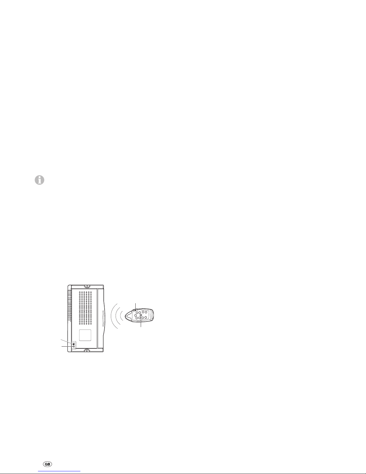
Synchronising the electronic control unit with
the radio remote hand set
The remote hand set and the control unit are synchronised with each other in the factory.
If the control unit or the remote hand set is replaced, they
must be re-synchronised as described below.
1. Check the installation in accordance with the installation
instructions and ensure that the drive rollers are not applied.
Check that the battery is properly connected, check the condition of the battery and that a voltage of 12 V is present at the
control unit. Please ensure that the caravan plug has been
plugged into the safety socket.
2. Press the reset button (k) on the control unit and hold down
(red LED – j – flashes slowly), and after approx. 5 seconds the
LED (j) starts to flash rapidly. Then release the reset button
and press and hold down the caravan reverse button on the
remote hand set (c) within 10 seconds, simultaneously switching on the remote hand set using the slide switch (a).
a
c
j
k
The remote hand set and the control unit are synchronised to
each other. After successful synchronisation, the red LED
flashes rapidly.
Manufacturer’s terms of warranty
1. Case of warranty
The manufacturer grants a warranty for malfunctions in the
appliance which are based on material or production faults.
In addition to this, the statutory warranty claims against the
seller remain valid.
A claim under warranty shall not pertain:
– for parts subject to wear and in cases of natural wear and
tear,
– as a result of using parts that are not original Truma parts in
the units,
– as a consequence of failure to respect the manufacturers
instructions for installation and use,
– as a consequence of improper handling,
– as a consequence of improper transport packing.
2. Scope of warranty
The warranty is valid for malfunctions as stated under
item 1, which occur within 24 months after conclusion of
the purchase agreement between the seller and the final
consumer. The manufacturers will make good such defects
by subsequent fulfilment, i.e. at their discretion either by
repair or replacement. In the event of manufacturers providing service under warranty, the term of the warranty shall not
re commence anew with regard to the repaired or replaced
parts; rather, the old warranty period shall continue to run.
More extensive claims, in particular claims for compensatory
damages by purchasers or third parties, shall be excluded.
This does not affect the rules of the product liability law.
The manufacturer shall bear the cost of employing the Truma
customer service for the removal of a malfunction under warranty – in particular transportation costs, travelling expenses,
job and material costs, as long as the service is carried out by
an authorised Truma-Dealer.
Additional costs based on complicated removal and installation conditions of the appliance (e.g. removal of furniture or
parts of the vehicle body) do not come under warranty.
Rollers carry 24 months warranty against manufacturing defects. Take care to remove sharp stones from your tyres prior
to using your Mover.
3. Raising the case of warranty
The manufacturer's address is:
Truma Geräte technik GmbH & Co. KG,
Wernher-von-Braun-Straße 12,
85640 Putzbrunn.
In Germany, always notify the Truma Service Centre if problems are encountered; in other countries the relevant service
partners should be contacted (see Truma Service Booklet or
www.truma.com). Com plaints must be specified. In addition,
the correctly completed warranty certificate must be presented or the Serial number of the appliance and the date of
purchase specified.
In order to allow the manufacturer to check whether it is a
warranty case, the end consumer must take or send the device to the manufacturer at his own risk.
In instances of the device being sent to the works, dispatch
is to be effected by freight transport. In cases under warranty,
the works shall bear the transport costs or the costs of delivery and return. If the damage is deemed not to be a warranty
case, the manufacturer shall notify the customer and shall
specify repair costs which shall not be borne by the manufacturer; in this case, the customer shall also bear the shipping
costs.
Page 5
17
Installation instructions
Read the installation instructions prior to starting work and
follow them carefully!
Please ensure that no metal chips or other contaminants get
into the controller during installation.
Intended use
The Mover SE R is designed for use on single-axle caravans
with a gross weight of up to 2000 kg,
and the Mover TE R is designed for use on dual-axle caravans with a gross weight of up to 2250 kg.
The Mover SE R / TE R weighs approx. 33 kg.
Check the towing load of your vehicle and the gross weight of
your caravan in order to establish whether they are designed
for the additional weight.
Approval
The Truma Mover SE R / TE R has design approval, and a
general operating permit (ABE) has been issued for Germany.
Acceptance by a vehicle expert is not required (except when
installing the flat frame kit). The ABE must be kept in the
vehicle.
The Mover SE R / TE R complies with the vehicle engine interference suppression directive 72/245/EEC with supplements
2004/104/EC, 2005/83/EC and 2006/28/EC and bears type
approval number: e1 03 4473
The Mover SE R / TE R complies with EMC directive 89/336/EEC
(2004/108/EC) and low voltage directive 73/23/EEC.
The remote hand set and the receiver comply with the
requirements of the R&TTE directive 1995/5/EC.
The Mover SE R / TE R satisfies the Machinery Directive
2006/42/EC.
The technical and administrative regulations of the country in
which the vehicle is initially registered must be complied with
when the Mover is being installed.
Any modifications to the unit or the use of spare parts and
accessories that are important to the operation of the system
that are not original Truma parts and failure to follow the installation and operating instructions will cancel the warranty
and indemnify Truma from any liability claims. In addition to
this, the operational approval for the device will be cancelled.
Tools and facilities required
To install the unit you will need
13 mm, 17 mm socket wrench, ring spanner or open-jawed
spanner
Torque wrench (5 – 40 Nm)
Cable cutter / Crimping tool
Power drill / screwdrivers / 25 mm hole cutter
Portable 2 tonne trolley jack and axle stands to suit
Appropriate lighting.
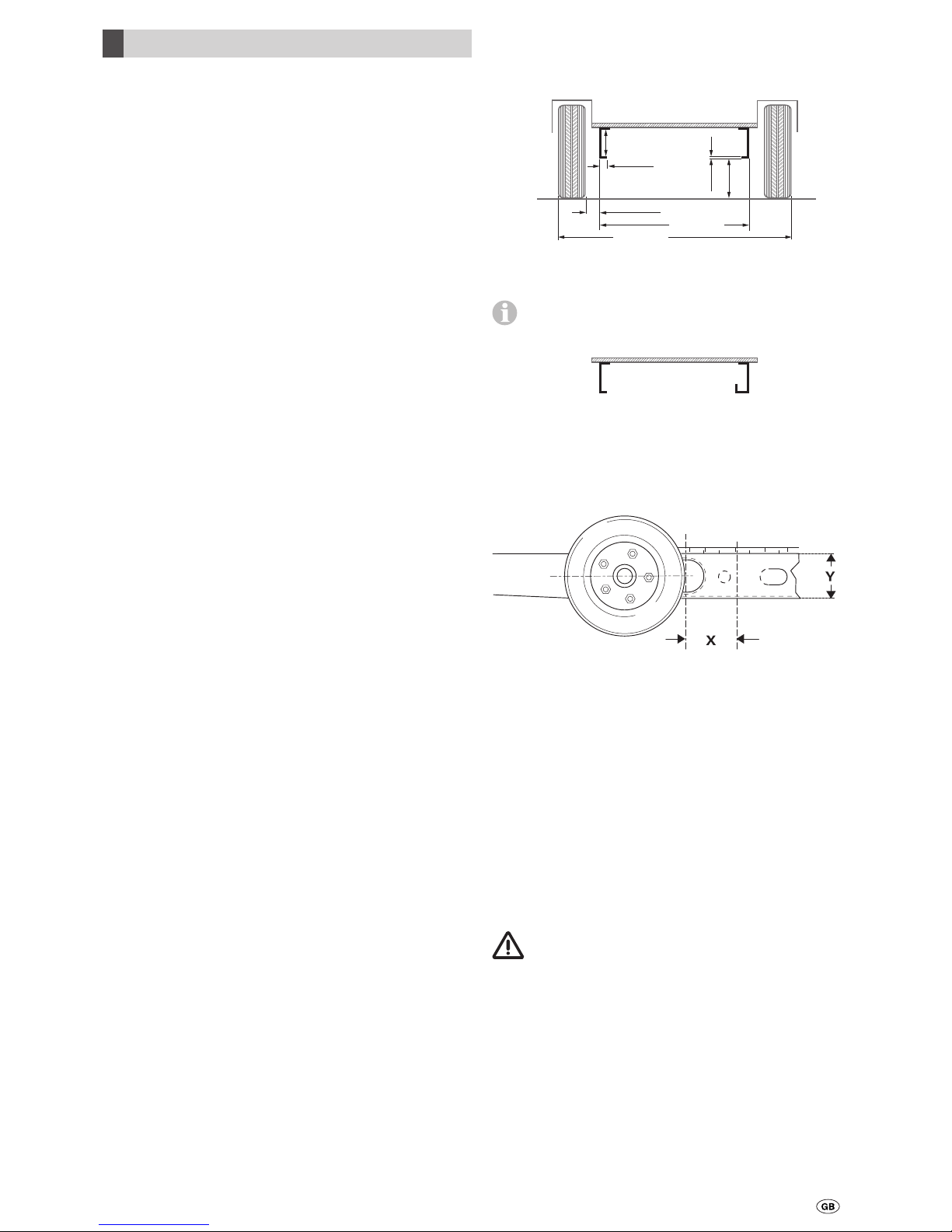
Minimum installation dimensions
The equipment can only be fitted to caravans / trailers within
the following dimensions.
min.
180*
max. 1860
max. 2400
min. 60
min. 30
max. 48
opt. 185
min. 2.8
max. 3.5
Caravan Floor
all dimensions in mm
* with fully loaded vehicle
A distinction is made between L-profiled and U-profiled
chassis as shown in the illustration.
Caravan Floor
L-Profile
U-Profile
Measuring the chassis height
Frame height (Y) measured at distance of 106 mm (X) from
the outer edge of the tyre at height of hub / middle of tyre.
Determining the installation type
1. Standard installation
Standard installation is used with a U-profile or L-profile chassis and a frame height (Y) of approx. 185 mm. No special
accessories are required.
2. Installation with chassis with U-profile or L-profile
and frame height of between 140 and 185 mm
With a chassis with a frame height (Y) of 140 mm to 185 mm,
1, 2 or 3 spacer plate sets and the screw set are needed to
compensate for the height.
3. Installation with chassis with U-profiles or L-profiles
with frame height of less than 140 mm
With a chassis with a frame height (Y) of less than 140 mm a
low chassis kit must be fitted to compensate for the height.
In Germany, the low chassis kit installation must
be accepted by a vehicle expert.
4. The AL-KO Vario III / AV installation kit must be used
with the AL-KO Vario III / AV chassis with a frame thickness of
less than 2.8 mm.
5. Installation with Eriba Touring chassis
The Eriba Touring mounting set is needed for the Eriba Touring
chassis.
Page 6
18
Special accessory installation
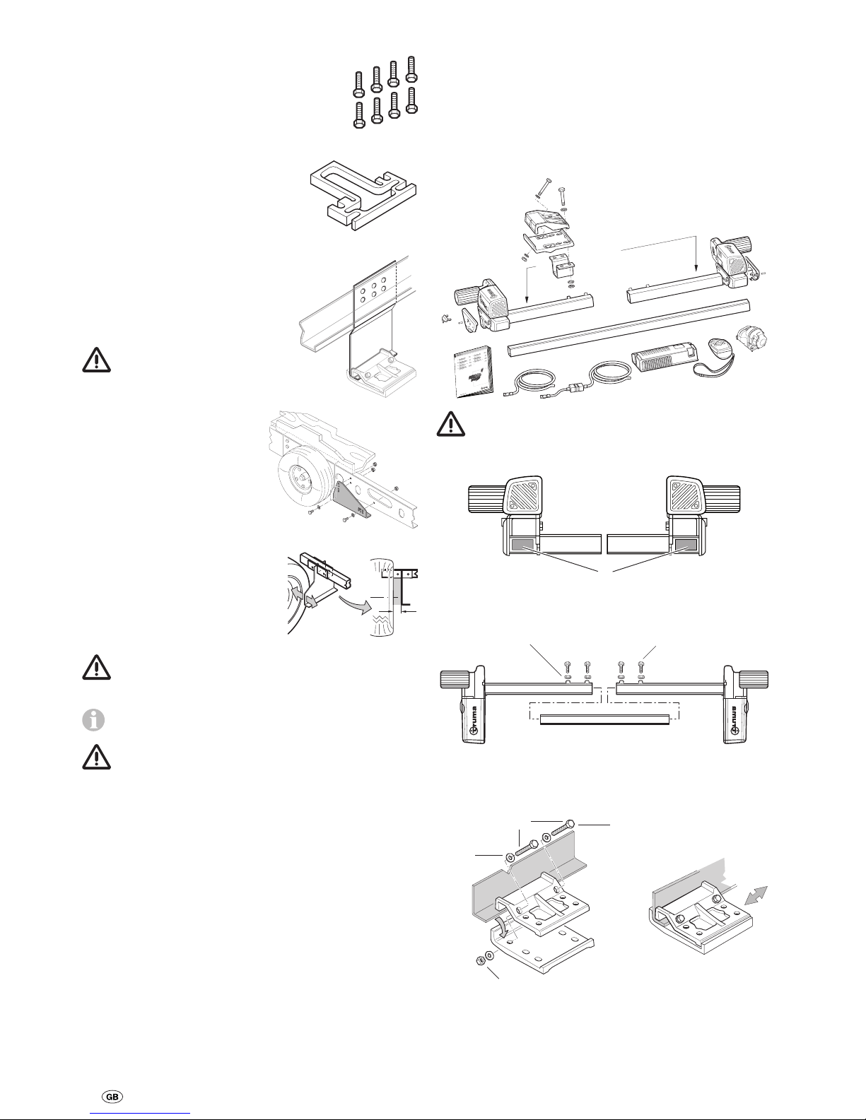
1. Set of screws
for height compensation with
spacer plates, max. 45 mm,
eight DIN 933 screws
M10 x 95 8.8, galvanized,
part no. 60010-70000.
2. Spacer plate kit
(two 15 mm spacer plates)
for height compensation
max. 45 mm (3 plates) at each
side (e.g. installed behind axle)
part no. 60010-66000.
3. Low chassis kit
for height compensation for
caravan / trailer with frame height
of less than 140 mm,
part no. 60010-64900.
In Germany, this installation kit must be accepted
by a vehicle expert.
4. AL-KO Vario III / AV
Installation kit
for caravans with
AL-KO Vario III / AV Chassis
(frame thickness less than 2.8 mm)
mandatory,
part no. 60010-21500.
5. Mover mounting set
for Eriba Touring
part no. 60030-09000.
60 - 100 mm
Installation is not possible in some cases because of
attachments to the underbody. Contact your dealer if
necessary.
Detailed installation instructions are provided with the
relevant mounting set.
The Mover SE R / TE R is not approved for installation on caravans / trailers with any other chassis!
Any drilling (exception: when using low chassis kit) or welding
to the chassis is not allowed. Under no circumstances remove
any suspension components from the chassis.
Choice of location
The Mover should preferably be installed in front of the axle,
but can also be installed behind the axle under special circumstances (e.g. lack of space). Only the bolts that are provided
must be used to secure the Mover (or the add-on parts
provided as special accessories).
Installation of the drive units
The frame of the vehicle must be kept free of rust and heavy
soiling and without any damages to the suspension
components.
The wheels and tyres that are fitted to the caravan must be of
the same size and model and inflated as per the manufacturer’s
instructions.
Remove all components from packing and place on the floor.
In order to maintain the validity of the General Operating
Permit (ABE) the provided factory plates (f) must be attached on the left and right sides of the cross strut between
the drive unit retaining plates.
f
Loosely attach the drive units to the lateral bar. The bolts
(lock nuts) must be no more than finger-tight.
Nut M8 (4 x) M8 x 30 (4 x)
Place the mounting set (b) on the vehicle frame and secure
using the two bolts (c), tight enough so that it can just about
be moved on the frame.
c
b
M8 x 60 (4 x)
Self-locking nut M8 (4 x)
Washer 8
(8 x)
Page 7
19
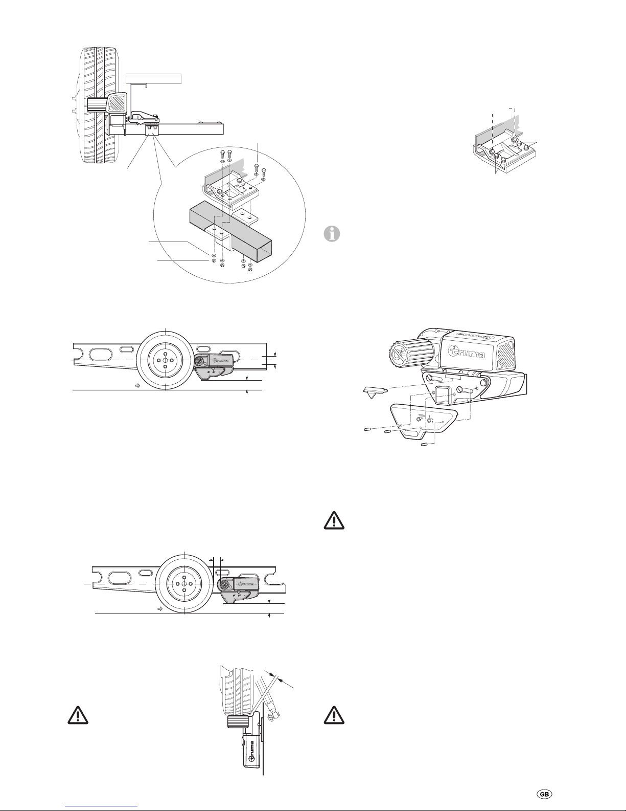
Bolt drive units with lateral bar to mounting set using U-bracket (d), tight enough so that it can just about be moved.
d
M10 x 50 (8 x)
Self-locking
nut M10 (8 x)
Washer 10
(16 x)
Position the drive rollers so that they are at approximately the
same height as the wheel hub (middle of wheel ± 30 mm).
± 30 mm
Driving direction
min. 110 mm
Truma can supply a spacer plate set for compensating for
height differences of up to 45 mm (part no. 60010-66000,
2 pcs. à 15 mm). Up to three spacer plates can be used at
each side. A bolt set (part no. 60010-70000) is needed to
attach the spacer plates.
The low chassis kit (part no. 60010-64900) must be used for
height differences of more than 45 mm. Check that there is
adequate ground clearance (min. 110 mm).
The correct distance can be set between the tyre and the roller
(20 mm) with the provided spacer by sliding the (disengaged)
drive units in the longitudinal direction. The movable middle
tube makes it possible to adapt to the width of the frame.
20 mm
min. 110 mm
Driving direction
Slide drive units in lateral direction so that the maximum
amount of tyre tread is covered.
Ensure that there is adequate
clearance between the gearbox
and the tyre / shock absorber so
that they do not touch.
The minimum clearance
with the drive units
engaged in is 10 mm.
min.
10 mm
After correctly positioning the bolts and nuts of the mounting
set, tighten slightly and then check the required distances /
clearances again. The weight of the caravan must be on the
wheels when doing this.
Move sliding middle tube to a central position (e.g. measure
at open side of middle tube with a pocket rule), tighten the
4 bolts (15 – 20 Nm) and secure the locknuts.
Re-check the distance of 20 mm
to the tyre (with weight on
wheels) and then tighten the
2 mounting set bolts (M 8) with
20 Nm and the 4 mounting set
bolts (M 10) with 40 Nm.
40 Nm
40 Nm
20 Nm
The bolt tightening order must be strictly adhered to for
correct installation.
Re-check that all 6 bolts have been tightened to the
correct torque!
Fit covering plates
Place covering plate onto housing and fix in position with
3 guide pins in each case (knock in with a hammer or screwdriver handle).
Installing the position indicator
Push the position indicator into the two holes in the gearbox.
Installation of motor cables and control unit
The Mover is only suitable for connection to 12 V batteries
(DC voltage).
Remove battery cable terminals and disconnect any
external electrical power before starting work. If you are
unsure about the electrical installation, have it checked out by
a qualified Auto Electrician.
Two high-power cables for the drive motor and a two-wire cable for the engagement motor are pre-attached to each motor.
Mark the respective motor connecting cables (motor A or B
– see also wiring diagram) and temporarily route to the intended control unit installation position on the underbody of the
caravan. An example of a suitable location for the control unit
is in a bed stowage box in close proximity to the manoeuvring
system, at least 40 cm away from the battery.
Insert control unit into stowage box and secure with the supplied chipboard screws (5 x 16).
Drill a 25 mm diameter hole on the floor of the caravan for
leading the cables through, approx. 150 mm from the control
unit terminal strip.
Take care to avoid any chassis members, gas pipes and
electrical wires!
Drill hole and lead cables through floor of caravan to control
unit in such a way that they cannot chafe (particularly when
leading through metal panels). This can be done using protective tubes, which will prevent the cables from being damaged.
Page 8
20
The drive motors move during operation. To com-
pensate for this, the cables should be secured loosely
with a little play in this area in order to prevent cable stretching. No cables must be routed over the control unit!
Secure cables to chassis and / or underbody using the supplied clips and screws.
Seal hole in vehicle underbody using plastic body sealant.
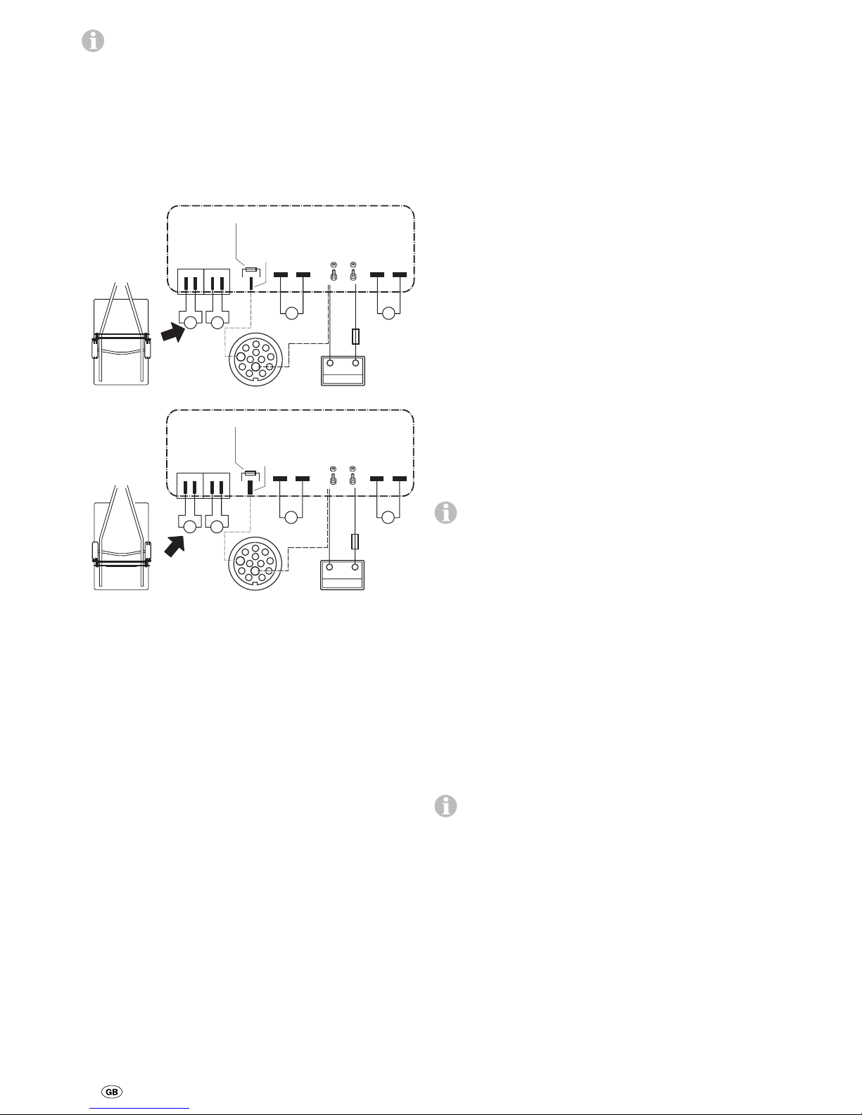
Connecting diagram
(with conventional brake lights)
Top-down
view
Safety
socket
Pin 6
Pin 3
Engagement
motors
Drive
motor
Drive
motor
Battery
Installation
in front of
axle
Safety
contact
Fuse
A
3
6
8
1
2
97
5
4
11
10
1213
– + – +
+ –
– +
B
A
1234
+
-
B
A
B
r
r
+ –
Top-down
view
Safety
socket
Pin 6
Pin 3
Engagement
motors
Drive
motor
Drive
motor
Battery
Installation
behind
axle
Safety
contact
Fuse
3
6
8
1
2
97
5
4
11
10
1213
– + – +
– +
– +
A
B
1234
+
-
B
A
r
r
– +
A
B
Connecting the drive motors
Cut motor cable of drive motor that is furthest away from
control unit to length. Shorten the motor cable of the nearest
drive motor to the same length. The two drive motor cables
must be of the same length to ensure that the drive output of
the Mover is uniform! Excess cable must be routed in wavy
lines without looping.
Crimp the provided flat plugs onto the drive motor cables.
Release flap at control unit terminal strip by pressing and connect cables as shown in wiring diagram (red = positive,
black = negative). Please ensure that the connections are
made properly!
Connecting the engagement motors
The positive connection (r) of the 2-wire motor connection
cables has been marked with a red longitudinal line along the
cable insulation.
Mark motor cables A + B and route to control unit (shorten
cables to same length if necessary).
Slide spade connector sleeve insulation over the cables
(e.g. black for motor A and transparent for motor B). Crimp on
spade connector sleeves, slide on spade connector sleeve
insulation and connect as shown in connecting diagram.
Connecting the battery
Route battery connecting cables (only use the original Truma
cables included in the delivery) to control unit and securely
attach using the provided clips and screws.
The battery connecting cables must not be extended.
They must be routed separately from the motor cables,
and must not run over the control unit.
Route battery connecting cables so that they do not chafe
(particularly at leadthroughs through metal panels). Use suitable leadthrough grommets for protection in order to prevent
damage to cables. Connect battery connecting cables to the
existing battery terminals (red = positive, black = negative).
The connection to the control unit (as per the connecting diagram) must take place in the order – nut, battery connection
ring, nut (torque 7 Nm ± 1).
Connect the fuse in the positive cable (150 A) close to the
positive contact.
Safety socket connection
with conventional brake lights
(applies to 7-pin and 13-pin sockets!)
The fact that there are two conventional brake lights and
a third brake light with LED technology does not affect
this connection.
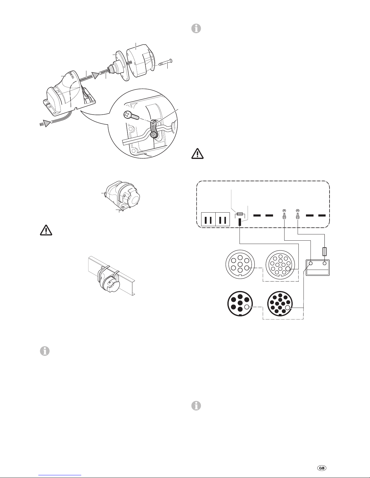
Route the provided 2-wire cable (10 m) with the wire-end ferrules through the socket holder (g) and the rubber sleeve (h).
Open cover and push socket connection out of socket housing (i).
Connect wire with longitudinal red stripe to pin 6 and black
wire to pin 3 (pin designation printed on connection and on
inside of cover).
Re-insert socket connection into socket housing (i).
Screw socket housing (i) to socket holder (g) using 3 sheet
metal screws (j). (Several alternative positions are available by
using the mounting holes in the socket holder and rotating the
rubber seal.)
Page 9
21
Loosely route cable through strain relief (k) and secure with
2 sheet metal screws. Depending on the installation situation,
the cable can be led out of the socket holder through one of
the three recesses.
j
B 3,9 x 33
(3 x)
i
h
Pin 3
Pin 6
g
B 3,5 x 9,5
k
Secure safety socket to the (plastic) shaft cover of the caravan with 4 bolts, nuts and washers.
M4 x 16
(4 x)
Washer 4,3
(4 x)
Nut M4 (4 x)
No holes must be drilled in the chassis.
Alternatively, the safety socket can be secured using the two
worm drive hose clamps.
Route wire connected to pin 6 (with red stripe) to control unit
(shorten if necessary), crimp on a flat plug and connect as
shown in the connecting diagram.
Route wire connected to pin 3 (black) to control unit (shorten
if necessary), crimp on a ring and screw to negative battery
terminal as shown in connecting diagram.
The connection to the control unit must be made in the
order – nut, battery negative terminal ring, nut, cable
pin 3 ring, nut.
Re-check whether all cables are correctly connected, attached
using the provided clips and cannot chafe.
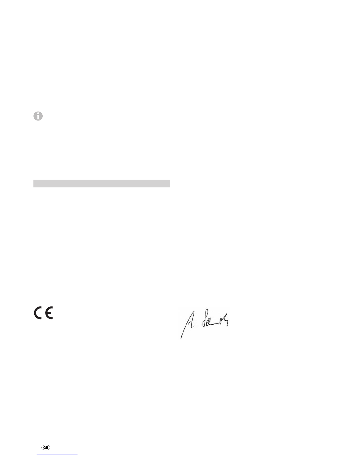
Safety socket connection with LED brake lights
This connection must always be used if all brake lights
are of the LED variety! With two conventional brake
lights and a third brake light with LED technology, the connection is made as described in “Safety socket connection with
conventional brake lights”.
7-pin safety socket
Connect pin 3 of the caravan plug to the negative battery
terminal.
Connect pin 3 of the safety socket to the controller (with one
wire of the 2-wire cable).
13-pin safety socket
Connect pin 11 of the caravan plug to the negative battery
terminal.
Connect pin 11 of the safety socket to the controller (with one
wire of the 2-wire cable).
If it is not possible to make a connection using pin 11 (pin
missing, for example), use pin 3 as an alternative.
It must be ensured that ground connections pin 11
and pin 3 are not interconnected in an electrically
conductive manner at the trailer side!
Connecting diagram with LED brake lights
1
+
-
Safety
socket
Engagement
motors
Drive
motor
Drivemotor
Battery
1
– + – +
– +
234
Caravan
plug
13-pin
3
11
8
1
2
97
5
4
6
10
1213
7-pin
3
4
6
7
1
5
2
11
3
8
1
2
97
5
4
6
10
1213
6
4
7
1
523
Safety
contact
Fuse
Commissioning the Mover
Ensure the battery used to operate the Mover is fully charged.
Park the caravan outside on an open, level surface and apply
the handbrake. Ensure that the rollers are disengaged from
the road tyres and the corner steadies are raised.
Connect battery terminals to battery, check that all cables are
secure and not hot or indicating signs of short circuits, etc.
Plug the 13-pin plug into the safety socket.
If there is a fault in both caravan brake lights, the power
circuit of the safety socket is not closed. In this case the
Mover cannot be operated.
Move slide switch on remote hand set to the “On” I position.
This switches the remote hand set on – green LED flashes for
5 seconds in combination with the acoustic alarm until the
control unit is ready for operation. If LED does not illuminate,
check polarity and condition of batteries in remote hand set.
Page 10
22
The remote hand set switches itself off after about 2 minutes
if no buttons are pressed.
Check whether both drive motors are stationary. Press the
“forwards” button with the remote hand set switched on –
both drive motors must now move in the forward direction.
Engage the drive rollers against the tyres by using the remote
hand set.
Please ensure that there are no obstructions beneath the caravan, then release the handbrake. Now check all functionality
as per the operating instructions.
Apply caravan handbrake. Disengage the drive rollers and
move slide switch on remote hand set to the “Off” £ position
to switch the remote hand set and the Mover off. Re-check
distance between drive rollers and tyres. Adjust if necessary.
The distance between the disengaged drive rollers and
the tyres is 20 mm.
Warning information
The yellow sticker with the warning information, which is
enclosed with the appliance, must be affixed by the installer
or vehicle owner to a place in the vehicle where it is clearly
visible to all users (e.g. on the wardrobe door)! Ask Truma to
send you a sticker, if necessary.
Technical data Mover SE R / TE R
Operational voltage
12 V DC
Current consumption
average approx. 35 A maximum 150 A
Stand by consumption
< 15 mA
Remote hand set frequency
Class 1, 868 MHz
Speed
approx. 17 cm per second (depending on weight and incline)
Weight
approx. 33 kg
Fuse engagement motors
Blade fuse 20 A
Fuse in positive supply cable
150 A
Area of operation Mover SE R
Single axle caravans with a total weight up to 2000 kg
Area of operation Mover TE R
Dual axle caravans with a total weight up to 2250 kg
Right to effect technical modifications reserved!
Conformity Declaration
1. Manufacturer master data
Name: Truma Gerätetechnik GmbH & Co. KG
Address: Wernher-von-Braun-Str. 12, D-85640 Putzbrunn
2. Equipment identification
Model / Version:
Mover S, Mover SE, Mover TE, Mover H SE, Mover H TE,
Mover SR, Mover SE R, Mover TE R manoeuvring aid
3. Complies with the requirements of the following
EC directives
3.1 R&TTE directive (1999/5/EC)
3.2 Low voltage directive (73/23/EEC)
3.3 EMC directive (89/336/EEC, 2004/108/EC)
3.4 Interference suppression in motor vehicles
(72/245/EEC, 2006/28/EC)
3.5 Machinery Directive 2006/42/EC
and bears the type approval number e1 03 4473 and the CE
symbol.
Mover S:
class 1, optional frequency 434 MHz or 868 MHz.
Mover SE / Mover TE / Mover H SE / Mover H TE / Mover SR /
Mover SE R / Mover TE R:
Class 1, frequency 868 MHz.
Countries:
AT, BE, BG, CH, CY, CZ, DE, DK, EE, ES, FI, FR, GB, GR, HU,
IE, IS, IT, LT, LU, LV, MT, NL, NO, PL, PT, RO, SE, SI, SK.
4. Basis of proof of conformity
EN300220-2:2006, EN300220-1:2006 (R&TTE art. 3.2),
EN301489-1:2005, EN301489-3:2002 (EMC art. 3.1b),
EN61000-4-2:2001, EN61000-4-3:2006, EN61000-4-6:2001,
EN55022:2003 (Class B), ISO 7637-2:2004,
EN60950:2001, 2006/28/EC, 2006/42/EC
5. Monitoring body
Federal Office for Motor Traffic
6. Information concerning position of undersigned
Signature: Dr. Schmoll
Executive Manager, Technology Putzbrunn, 15.12.2008
 Loading...