

Page 1
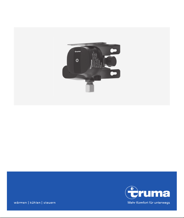
MonoControl CS
EN Operating instructions To be kept in the vehicle Page 02
Page 2

MonoControlCS
Table of contents
Symbols used .................................................................................... 3
Intended use ................................................................................... 3
Safety instructions ........................................................................ 4
Operating instructions
Start-up ............................................................................................ 7
Crash sensor ................................................................................... 8
Changing the gas cylinder ........................................................... 8
Hose change ................................................................................... 9
Checking for leaks in the high-pressure section ................... 10
Checking for leaks in the low-pressure section .................... 10
Maintenance ................................................................................. 12
Accessories ................................................................................... 13
Technical data .............................................................................. 14
Manufacturer’s Warranty
(European Union) ......................................................................... 15
2 EN
Page 3

Symbols used
The unit may only be installed and repaired by
an expert. Experts are persons who, based on
their specialist instruction and training, their
knowledge and experience with Truma products
and the relevant standards, can carry out the
necessary work properly and identify potential
hazards.
Symbol indicates possible hazards.
Note containing information and tips.
Intended use
MonoControl CS is a safety gas pressure regulator for caravans and motor homes. The gas pressure regulator ensures a uniform output pressure
of 30 mbar with a permissible inlet pressure range of 0.3 – 16bar.
The integrated crash sensor (CS) interrupts the flow of gas in the
event of an accident with directly acting deceleration of 4.0
The MonoControlCS gas pressure regulator with safety valve is a
single-stage gas pressure regulator. If the gas pressure regulator is
not working properly, for example due to dirt or other foreign material
on the valve, the safety valve opens and blows off to a pressure of
110mbar.
g
± 1.0g.
3EN
Page 4

Using the MonoControl CS in closed rooms (e.g. at home), on boats
or in EX Zone 0 (e.g. tankers) is prohibited.
The national regulations must be observed if there is a possibility of it
being used in mobile homes. Its use in mobile homes is prohibited in
Germany.
An automatic PRV* safety device integrated in the MonoControl CS
with limited flow protects the connected consumers against impermissibly high pressure. As soon as an impermissibly high pressure
arises on the output side, the PRV opens and blows out the overpressure into the air. The PRV closes automatically after the pressure is
reduced.
* = Pressure Relief Valve
MonoControlCS must not be used for commercial purposes.
Safety instructions
– Do not connect any electrical appliances or other potential ignition
sources if you can smell gas or if there is a leak in the gas system.
Close the cylinder valve, have the gas system repaired by an expert
immediately and do not open the valve in the meantime.
– The use of upright gas cylinders from which gas is extracted in
the gas phase is mandatory when operating the MonoControl CS
gas pressure regulator. Gas cylinders from which gas is taken in the
liquid phase (e.g. for fork lifts) must not be used, since they would
result in damage to the gas system.
4 EN
Page 5

– A gas filter must be installed upstream of the gas pressure regula-
tor inlet to provide reliable protection against dirt / oiling. A set of
operating and installation instructions is supplied with the gas filter.
– A high-pressure hose with hose rupture protection (HRP) is manda-
tory for connecting the gas cylinder to the gas pressure regulator or
gas filter. For this, Truma provides the necessary high-pressure hoses with the most commonly-used connection variants for European
gas cylinders (see www.truma.com).
– In normal conditions of use, in order to ensure correct operation of
the installation it is recommended that this device is changed within 10 years of the date of manufacture. National regulations must
be observed. The operator is responsible for this.
Operating the gas system while driving:
– The appliance manufacturer’s instructions must be followed before
operating a liquid gas appliance while driving.
– For heating while driving, the regulation (EC) No. 661/2009 and the
binding UN/ECE regulation R 122 stipulate a safety shut-off device
for motor homes and caravans.
The MonoControl CS gas pressure regulator satisfies this requirement.
Installing a safety shut-off device such as the MonoControl CS gas
pressure regulator with appropriately configured gas installation
means that a type-tested liquid gas heater may be used in line with
the aforementioned regulation while driving throughout Europe.
National regulations and rules must be followed.
5EN
Page 6
– For vehicles manufactured before 01/2007 there are no restrictions
for operating the gas system while driving *.
* Except for France:
In France, operation of a gas system while driving is only permitted
in type-tested vehicles with first registration as of 01.01.2007. In
older vehicles the operation of the gas system while driving is also
non-permissible in combination with a safety shut-off device.
– Gas cylinders that are not connected to the gas installation must
be closed at all times and provided with protection caps. Connected gas cylinders are considered to be operating materials and not
hazardous materials (ADR exemption in accordance with sections
1.1.3.1 and 1.1.3.2 e).
Operating instructions
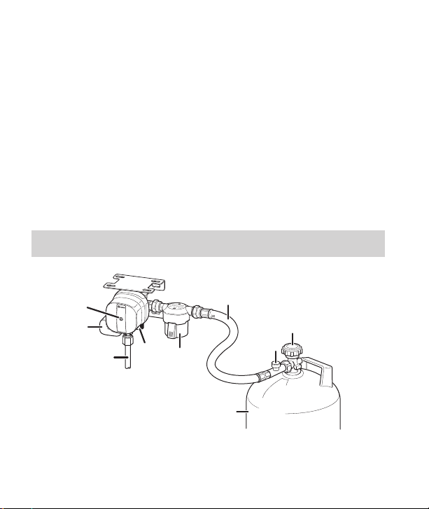
Figure 1a
6 EN
7
6
10
8
5
4
1
3
2
Page 7
9
11
12
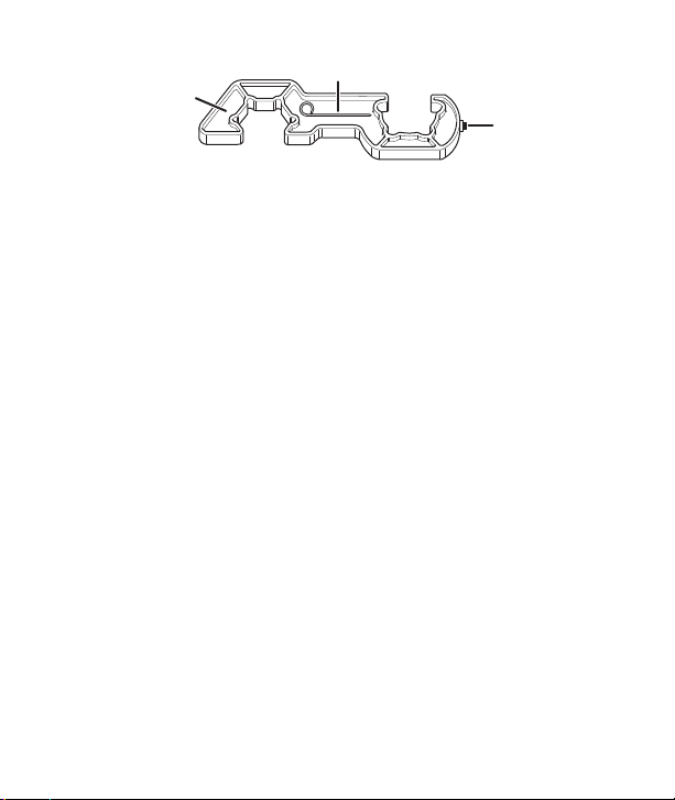
Figure 1b
1 = Cylinder valve
2 = Gas cylinder
3 = Hose rupture protection (HRP)
4 = High-pressure hose
5 = Gas filter
6 = MonoControl CS
7 = Yellow reset button of the crash sensor
8 = Steel / copper tube
9 = Triggering element for the crash sensor
10 = Screw cap (test connection)
11 = Screw aid a/f 23 / KF
12 = Torx T20 (on the screw aid)
Start-up
– Open the gas remote switch if present.
– Connect the gas cylinder (2) and ensure that the hose connection is
in perfect condition.
– Open the cylinder valve(1).
– Firmly press the hose rupture protection (figure1a–3) on the
high-pressure hose for about 5 seconds.
7EN
Page 8
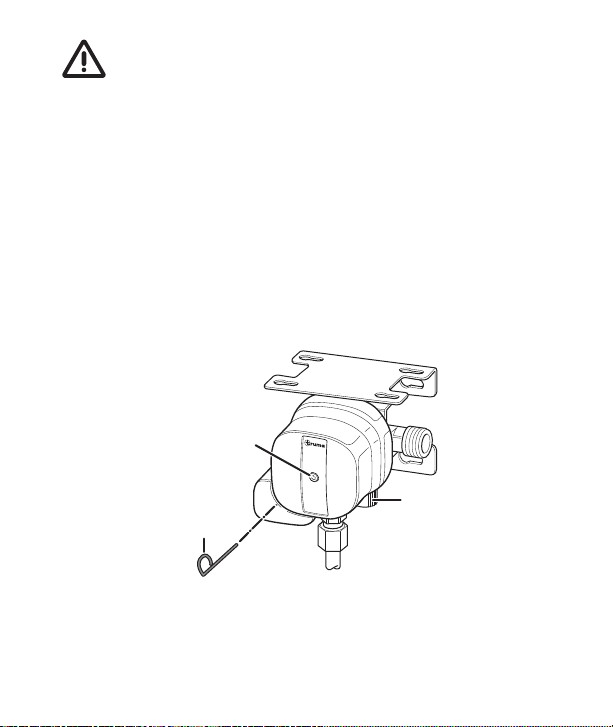
– If the yellow reset button (7) is not pressed (“not ready for opera-
tion” position), reset the crash sensor.
Crash sensor
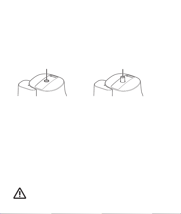
The crash sensor has a reset button, the position of which indicates
its status: “Ready for operation” position (Figure2a) or “not ready for
operation” position (Figure2b).
7
Figure 2a Figure 2b
To reset, press the yellow reset button (7) firmly, turn it slightly clockwise, hold it for 5 seconds and ensure that it stays in the “ready for
operation” position (Figure 2a).
If the reset is not successful, use the Torx T20(12) on the screw aid (11)
to support the clockwise rotation.
7
Changing the gas cylinder
Use the included screw aid (11) to attach and remove the high-pressure hose (4). It will help you generate the necessary tightening
torque and will prevent damage to the union that may otherwise result from using an improper tool.
Residual gas: No smoking, no naked flames!
8 EN
Page 9
– Close the valve (1) of the empty gas cylinder (2).
– Remove the high-pressure hose (4) from the gas cylinder (2) and
remove the clip-on adapter, if present.
– Attach the high-pressure hose to the full gas cylinder and fit the clip-
on adapter, if present. Change the filter pad of the gas filter.
– Open the full gas cylinder’s valve (1).
– Press the hose rupture protection (figure1a–3) and if necessary
the yellow reset button (7), turn it slightly clockwise and hold it for
5seconds.
After any intervention, check the hose connection to the cylinder valve for leaks (see “Checking for leaks in the high-pressure
section”).
Hose change
Use the included screw aid (11) to attach and remove the high-pressure hose (4). It will help you generate the necessary tightening
torque and will prevent damage to the union that may otherwise result from using an improper tool.
Residual gas: No smoking, no naked flames!
– Close the gas cylinder valve (1).
– Unscrew the high-pressure hose (4) from the gas cylinder (2 / or the
clip-on adapter) and from the gas filter / MonoControl CS inlet.
9EN
Page 10

When changing the hose, ensure that the seal provided with
the hose (hose outlet – gas filter / regulator inlet) is correctly
installed and not damaged.
We recommend that the flat gasket G 13 (part no. 50020-76300)
be replaced every time the hose is changed.
– Screw the country-specific high-pressure hose (4) to the gas filter(5)/
MonoControl CS inlet and to the cylinder (2 / or the clip-on adapter).
– Open the cylinder valve(1).
– Press the hose rupture protection (figure1a–3) and if necessary
the yellow reset button (7), turn it slightly clockwise and hold it for
5seconds.
– After any intervention, check the hose connection on the cylinder
valve and at the gas filter / MonoControlCS inlet for leaks (see
“Checking for leaks in the high-pressure section”).
Checking for leaks in the high-pressure section
The screw joint of the high-pressure hose at the gas cylinder valve
and on the gas filter / MonoControl CS must be checked for leaks
using suitable means such as a leak-finder spray in accordance with
EN 14291. The operator is responsible for this.
Checking for leaks in the low-pressure section
(maximum test pressure 150 mbar)
10 EN
Page 11
The test must be conducted by a technician
The gas hose and gas cylinder must be connected.
– Turn off all consumers.
– Open stop valves and, if present, the gas remote switch.
– Press in the triggering element of the crash sensor (9) sufficiently
far that the yellow reset button(7) comes out so that the crash sensor is in the “not ready for operation” position (figure 2b).
– Remove the screw cap (10) from the test connection and connect
the test pump with test hose to the test connection.
7
10
9
Figure 3: MonoControl CS
– Check for leaks (e.g in Germany in accordance with G 607).
11EN
Page 12

– If there is a gas system leak, close the cylinder valve, have the gas
system repaired by an expert immediately and do not open the
valve any more in the meantime.
– Unscrew the pump from the test connection and screw the screw
cap back onto the test connection.
– Press the yellow reset button(7), turn it slightly clockwise, hold it
for 5 seconds and ensure that it remains in the “ready for operation” position (see Figure2a).
– It is essential to reattach the screw cap (10) every time after it has
been removed.
Maintenance
The MonoControl CS gas pressure regulator is maintenance-free.
In Germany, the gas system must be retested every 2 years by a liquefied gas specialist (DVFG, TÜV, DEKRA). The test must be confirmed
on the respective test certificate (G 607).
In countries where testing is not mandatory, we recommend that the
gas system be tested every 2 years for your own safety.
The filter pad in the gas filter must be replaced every time the gas cylinder is replaced (see gas filter operating instructions).
12 EN
Page 13

Accessories
High-pressure hoses (Art. No. list – see www.truma.com)
with hose rupture protection and country-specific connections
Flat gasket G.13 (part no. 50020-76300)
for high-pressure connection, M20x1.5 (G.13)
Plug-fit EisEx 12 V (part no. 53101-01)
Gas remote switch GS 8 (Art. No. 57014-01)
Gas remote switch GS 10 (Art. No. 57024-01)
both for shutting off the gas supply from inside the vehicle
Gas filter (Art. No. 50603-01)
suitable for all wall-mounted gas pressure regulators with inlet fitting
M20 x 1.5 (male thread – G.13). Install upstream of the gas pressure
regulator.
13EN
Page 14
Technical data
(determined in accordance with EN 16129:2013 or Truma test conditions)
Gas type
Liquefied gas (propane / butane)
Admission pressure
0.3 – 16bar
Output pressure
30 mbar
Regulator capacity
1.5 kg/h
Regulator inlet
Male thread M20 x 1,5 (G.13)
Regulator outlet
Olive screw connection 8 mm or 10 mm (H.9)
Recommended tightening torque
3–5Nm for union nut M20x1.5 (G.13);
14–19Nm for olive screw connection 8mm;
16–21Nm for olive screw connection 10mm
Horizontal triggering value
g
± 1.0
4.0
Operating temperature
-20 °C to +50 °C
Product ID number: CE-0085CT0438
g
Subject to technical changes.
14 EN
Page 15

Manufacturer’s Warranty
(European Union)
1. Scope of Manufacturer’s Warranty
As the Manufacturer of the appliance, Truma undertakes a warranty
towards the Consumer that covers any material and/or manufacturing
defects of the appliance.
This Warranty is applicable in EU member states as well as in Iceland,
Norway, Switzerland and Turkey. A Consumer is the natural person
who was the first one to purchase the appliance from the Manufacturer, OEM or dealer and who neither resold the appliance in a commercial or self-employed professional capacity nor installed it for a
third party in such a capacity.
The Manufacturer’s Warranty covers any of the aforementioned
defects that occur within 24 months upon concluding the purchase
agreement between the seller and the Consumer. The Manufacturer
or an authorised service partner undertakes to remedy such defects
through subsequent fulfilment, i.e. at its discretion either by repairing
or replacing the defective item. Defective parts shall become the
property of the Manufacturer or the authorised service partner. If the
appliance is no longer manufactured at the time of defect notification
and if replacement delivery has been opted for, then the manufacturer
may deliver a similar product.
If the Manufacturer remedies a defect under its Warranty commitment, the term of the Warranty shall not start again with regard to the
repaired or replaced parts; rather, the original warranty period shall
continue to be applicable to the appliance.
15EN
Page 16

Only the Manufacturer itself and an authorised service partner shall
be entitled to conduct a warranty job. Any costs that occur in the
event of a warranty claim shall be settled directly between the authorised service partner and the Manufacturer. The Warranty does not
cover additional costs arising from complicated removal or installation
jobs on the appliance (e.g. dismantling of furnishings or parts of the
vehicle body), and neither does it cover travel expenses incurred by
the authorised service partner or the Manufacturer.
No further-reaching claims shall be permitted, especially damage claims presented by the Consumer or third parties. This shall
not affect the provisions of the German Product Liability Act
(Produkthaftungsgesetz).
The voluntary manufacturer’s warranty does not affect the consumer’s
legally valid claims for defects against the seller in the relevant country
of purchase. In individual countries there may be warranties that can
be issued by the relevant dealer (official distributor, Truma Partner).
In such cases the warranty can be implemented directly through the
dealer from whom the Consumer bought the appliance. The warranty
regulations of the country in which the appliance was purchased by
the Consumer for the first time shall also be applicable.
2. Warranty exclusions
No warranty claim shall be applicable under the following
circumstances:
– Improper, unsuitable, faulty or negligent use and any use that is not
compliant with the intended purpose
– Improper installation, assembly or commissioning, contrary to op-
erating or installation instructions
16 EN
Page 17

– Improper operation or operation contrary to operating or installa-
tion instructions, particularly any disregard for maintenance, care
or warning notes,
– Instances where installations, repairs or any other procedures have
been conducted by non-authorised parties
– Consumable materials and parts which are subject to natural wear
and tear
– Installation of replacement, supplementary or accessory parts
that are not original manufacturer’s parts or which have not been
approved by the manufacturer. This applies in particular if the appliance is subject to networked control, if the control units or the
software have not been approved by Truma or if the Truma control
unit (e.g. Truma CP plus or Truma iNet Box) has not been exclusively used for controlling Truma appliances or appliances approved by
Truma.
– As a consequence of damage arising from foreign substances (e.g.
oil, or plasticisers in the gas), chemical or electrochemical influences
in the water, or cases when the appliance has come into contact
with unsuitable substances (e.g. chemical products, flammable
substances or unsuitable cleaning agents)
– Damage caused by abnormal environmental or unsuitable operat-
ing conditions
– Damage caused by force majeure or natural disasters or any other
influences not within Truma’s responsibility
– Damage resulting from improper transport
– End customer’s or third-party modifications of the appliance, in-
cluding any replacement, supplementary or accessory parts, or
installation of the same, especially concerning the exhaust gas
system or the cowl.
17EN
Page 18

3. Making a warranty claim
The warranty must be claimed with an authorised service partner or
at the Truma Service Centre. All the relevant addresses and phone
numbers can be found at www.truma.com, in the “Service” section.
The Manufacturer‘s address is:
Truma Gerätetechnik GmbH & Co. KG
Truma Servicezentrum
Wernher-von-Braun-Straße 12
85640 Putzbrunn, Germany
To ensure a smooth procedure, we would be grateful if you could
have the following details ready before contacting us:
– Detailed description of the defect
– Serial number of the appliance
– Date of purchase
The authorised service partner or the Truma Service Centre will then
specify the further procedure. To avoid transport damage, the affected appliance must only be shipped by prior arrangement with the
authorised service partner or the Truma Service Centre.
If the warranty claim is recognised by the Manufacturer, then the
transport expenses shall be borne by the same. If no warranty claim is
applicable, the Consumer will be notified accordingly and any repair
and transport expenses shall then be the Consumer’s liability. We ask
you not to send in an appliance without prior arrangement.
18 EN
Page 19

DE Bei Störungen wenden Sie sich bitte an das Truma Servicezentrum oder an
einen unserer autorisierten Servicepartner (siehe www.truma.com). Für eine
rasche Bearbeitung halten Sie bitte Gerätetyp und Seriennummer (siehe
Typenschild) bereit.
EN Should problems occur, please contact the Truma Service Centre or one of our
authorised service partners (see www.truma.com). In order to avoid delays,
please have the unit model and serial number ready (see type plate).
FR Veuillez vous adresser au centre de SAV Truma ou à un de nos Service Partner
agréés en cas de dysfonctionnements (voir www.truma.com). Pour un traitement
rapide de votre demande, veuillez tenir prêts le type d’appareil et le numéro de
série (voir plaque signalétique).
IT In caso di guasti rivolgersi al centro di assistenza Truma o a un nostro
ServicePartner autorizzato (consultare il sito www.truma.com). Affinché la
richiesta possa essere elaborata rapidamente, tenere a portata di mano il
modello dell’apparecchio e il numero di matricola (vedere targa dati).
Truma Gerätetechnik
GmbH & Co. KG
Wernher-von-Braun-Straße 12
85640 Putzbrunn
Deutschland
Service
50020-00309 · 02 · 04/2019 · ©
 Loading...