

Page 1

50020-21200 · 02 · 03/2006 · 6’B · ©
Gebrauchsanweisung Seite 2
Einbauanweisung
Im Fahrzeug mitzuführen!
Operating instructions Page 6
Installation instructions
To be kept in the vehicle!
Mode d’emploi Page 9
Instructions de montage
À garder dans le véhicule !
Gebruiksaanwijzing Pagina 13
Inbouwhandleiding
Moet in uw voertuig meegenomen worden!
Duomatic L plus
AB
Duomatic L Plus
Version „DE“
Truma Gerätetechnik
GmbH & Co. KG
Wernher-von-Braun-Straße 12
85640 Putzbrunn
Service
Telefon +49 (0)89 4617-2142
Telefax +49 (0)89 4617-1259
[email protected]
www.truma.com
Page 2
B
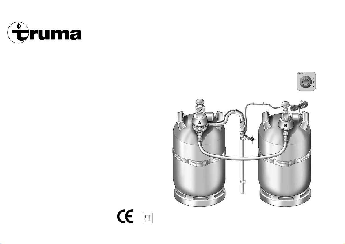
Duomatic L Plus
Gasdruckregler-Set mit Umschaltautomatik
und Fernanzeige für die Zweiflaschenanlage
Gas pressure regulator set with automatic
switchover and remote display for two-cylinder
system
Kit de détendeurs de gaz avec commutation
automatique et téléaffichage pour une
installation à deux bouteilles
Gasdrukregelaar-set met automatische
omschakeling en afstandsindicatie voor
tweeflesseninstallatie
Duomatic L plus
AB
Page 3
C
A
B
max. 65 cm
14
2
5
1
55 mm
A
3
6
4
B
9
15
16
12 V
12
8
9
13
7
10
11
11
Page 4
2
Gebrauchsanweisung
Das Gasdruckregler-Set
Duomatic L Plus besteht aus
einem Zentralregler „A“ und
einem Umschaltregler „B“.
Diese gewährleisten einen
gleichmäßigen Gasdruck
(30 oder 50 mbar), unabhängig davon, welche der beiden
Flaschen Gas liefert.
Die Kontrolllampen an der im
Innenraum angebrachten
Fernanzeige informieren Sie,
ob die Gasflaschen betriebsbereit sind.
Am Umschaltregler „B“ können Sie mit dem Drehknopf
(1) bestimmen, welche der
Gasflaschen jeweils als Betriebs- oder Reserveflasche
verwendet werden soll.
Steht z.B. der Drehknopf (1)
im roten Bereich, wird vorrangig Gas aus der Flasche
mit dem Zentralregler „A“
entnommen. Die Gasflasche
mit dem Umschaltregler „B“
dient dann als Reserveflasche. Steht dagegen der
Drehknopf (1) im grünen Bereich, wird im umgekehrten
Sinne vorrangig Gas der
Flasche mit dem Umschaltregler „B“ entnommen und
die Gasflasche mit Zentralregler „A“ dient als Reserveflasche.
Drehknopf immer bis
zum Anschlag drehen.
Die am Drehknopf festgelegte
Betriebsflasche wird immer
zuerst entleert. Das Gasdruckregler-Set schaltet dann automatisch auf die vorher festgelegte Reserveflasche um.
Bei eingeschalteter Fernanzeige erlischt die entsprechende Kontrolllampe („A“
oder „B“) und signalisiert
eine leere Gasflasche.
Wichtige Hinweise
1. Gasflaschen immer senkrecht stellen und gegen Umfallen sichern (insbesondere
33 kg-Flaschen)!
2. Die Regler sind mit einem
Kombinationsanschluss ausgestattet und eignen sich für
handelsübliche 3 kg-, 5 kg-,
11 kg-, und 33 kg-Gasflaschen.
3. Gasschläuche nicht
knicken oder stark biegen!
4. Soll die Gasanlage mit nur
einer Gasflasche (z.B. im
Sommer) betrieben werden,
ist der Zentralregler „A“ zu
verwenden. Der Drehknopf
(1) am Umschaltregler „B“ ist
in den roten Bereich zu drehen. Den nicht verwendeten
Umschaltregler „B“ am Reglerhalter (14) einhängen, um
diesen vor Beschädigungen
zu schützen.
5. Das Manometer (2) am
Zentralregler zeigt nicht den
Gasflascheninhalt, sondern
den momentanen (von der
Umgebungstemperatur abhängigen) Druck in der Gasflasche an. Zur Inhaltsmessung der Gasflaschen bietet
Truma das Ultraschall-Füllstandsmessgerät Sonatic
bzw. Sonatic Duo an. Bitte
informieren Sie sich hierzu im
Fachhandel.
6. Druckregelgeräte und
Schlauchleitungen sind spätestens 10 Jahre nach Herstellerdatum gegen neue auszuwechseln. Der Betreiber ist
dafür verantwortlich.
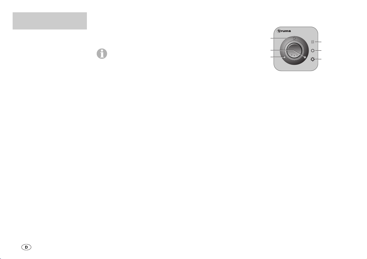
Inbetriebnahme
a = Ein (Sommerbetrieb)
b=Aus
c = Ein und Heizen
(Winterbetrieb)
d = Betriebsanzeige
e = Kontrolllampe A
f = Kontrolllampe B
Sommerbetrieb:
Schalter nach unten (a), die
Betriebsanzeige (d) leuchtet.
Die Kontrolllampen A und B
leuchten, wenn die Gasflaschen betriebsbereit sind.
Winterbetrieb:
Schalter nach oben (c). Die
Betriebsanzeige (d) leuchtet
und die Gasdruckregler werden zusätzlich beheizt, um
eine störungsfreie Gasversorgung im Winter zu gewährleisten (Stromaufnahme 640 mA).
Die Kontrolllampen A und B
leuchten, wenn die Gasflaschen betriebsbereit sind.
Duomatic L Plus
d
f
e
A
c
b
a
B
Page 5
3
Technische Daten
Spannung: 12 V
Stromaufnahme
Sommerbetrieb: 20 mA
Winterbetrieb: 620 mA
Betriebsdruck
Zentralregler:
30 oder 50 mbar
Umschaltregler:
100 bzw. 220 mbar
(abhängig von der Position
des Umschaltventils)
Durchflussmenge:
1,5 kg/h
Reglerausgangsanschluss:
Außengewinde H.4
(entspricht 1/4“ links)
Konformitätserklärung:
Das Truma GasdruckreglerSet Duomatic L Plus entspricht der DruckgeräteRichtlinie 97/23/EG unter
Anwendung der EN 12864/D
und EN 13786/B. Zusätzlich
ist das Gasdruckregler-Set
mit einem Sicherheitsventil
ausgestattet, so dass bei einem Defekt kein Druck über
100 mbar an die Geräte
kommen kann.
Produkt-Ident-Nummer:
CE-0085BN0539
EWG-Typgenehmigung:
e1 022603
Ausschalten:
Schalter in Mittelstellung (b).
Am Bedienteil werden
nur die elektrischen
Funktionen ein- und ausgeschaltet. Die Gasversorgung
selbst wird mechanisch an
den Gasflaschen auf- bzw. zugedreht. Zur zentralen Absperrung der Gasversorgung
– vom Innenraum aus – bietet
Truma einen Gasfernschalter
als Zubehör an. Bitte informieren Sie sich hierzu im
Fachhandel.
Flaschenwechsel
Das Gasdruckregler-Set bietet Ihnen die Möglichkeit,
eine leere Gasflasche auszuwechseln, ohne den Betrieb
der Verbrauchseinrichtungen
zu unterbrechen (Ihre Geräte
werden aus der Reserveflasche weiterversorgt).
Ist eine Kontrolllampe (A oder
B) erloschen, ist die entsprechende Gasflasche leer.
Ventil an der leeren Gasflasche schließen und Regler
von der Flasche abschrauben.
Beim Flaschenwechsel
nicht rauchen und
offene Flammen vermeiden!
Nachdem Sie die leere Gasflasche gewechselt haben,
sollten Sie am Drehknopf (1)
mit einer einfachen Drehung
um 180° die Gasentnahme
wechseln. Die ehemalige
Reserveflasche wird nun zur
Betriebsflasche. Die neue,
voll gefüllte Gasflasche steht
dann als Reserve zur Verfügung.
Leckprüfung
1. Alle Geräte abstellen.
2. Gasflaschen und Schnellschlussventile in den Gasleitungen öffnen.
3. Druck am Manometer (2)
ablesen und die Gasflaschen
wieder schließen.
4. Zeigt das Manometer (2)
nach 10 Minuten immer noch
den gleichen Druck, ist die
Gasanlage dicht. Fällt der
Druck ab, ist die Gasanlage
undicht und muss unver-
züglich von einem Fachmann
in Ordnung gebracht werden.
Flaschenventile nicht mehr
öffnen!
Diese Leckprüfung
gibt nur einen groben
Überblick und ersetzt nicht
die regelmäßig wiederkehrende Gasprüfung!
Page 6
4
Einbauanweisung
Der Betriebssdruck der
Duomatic L Plus
(30 oder 50 mbar – siehe Aufdruck am Zentralregler „A“)
muss mit dem Betriebsdruck
der im Fahrzeug eingebauten
Geräte übereinstimmen!
Einbau nur vom Fachmann!
Die Duomatic L Plus ist nur
zulässig für Wohnwagen und
Reisemobile mit Aufstellung
der Gasflaschen im Freien
bzw. in Schränken, die gegen
den Fahrzeug-Innenraum
dicht ausgeführt sind!
Der Einbau in gewerblich genutzten Fahrzeugen, in geschlossenen Räumen (Haushalt), in Mobilheimen oder
auf Booten ist nicht zulässig.
Bei Verwendung von fahrzeug- bzw. herstellerspezifischen Bedienteilen muss der
elektrische Anschluss gemäß
der Truma-Schnittstellenbeschreibung erfolgen.
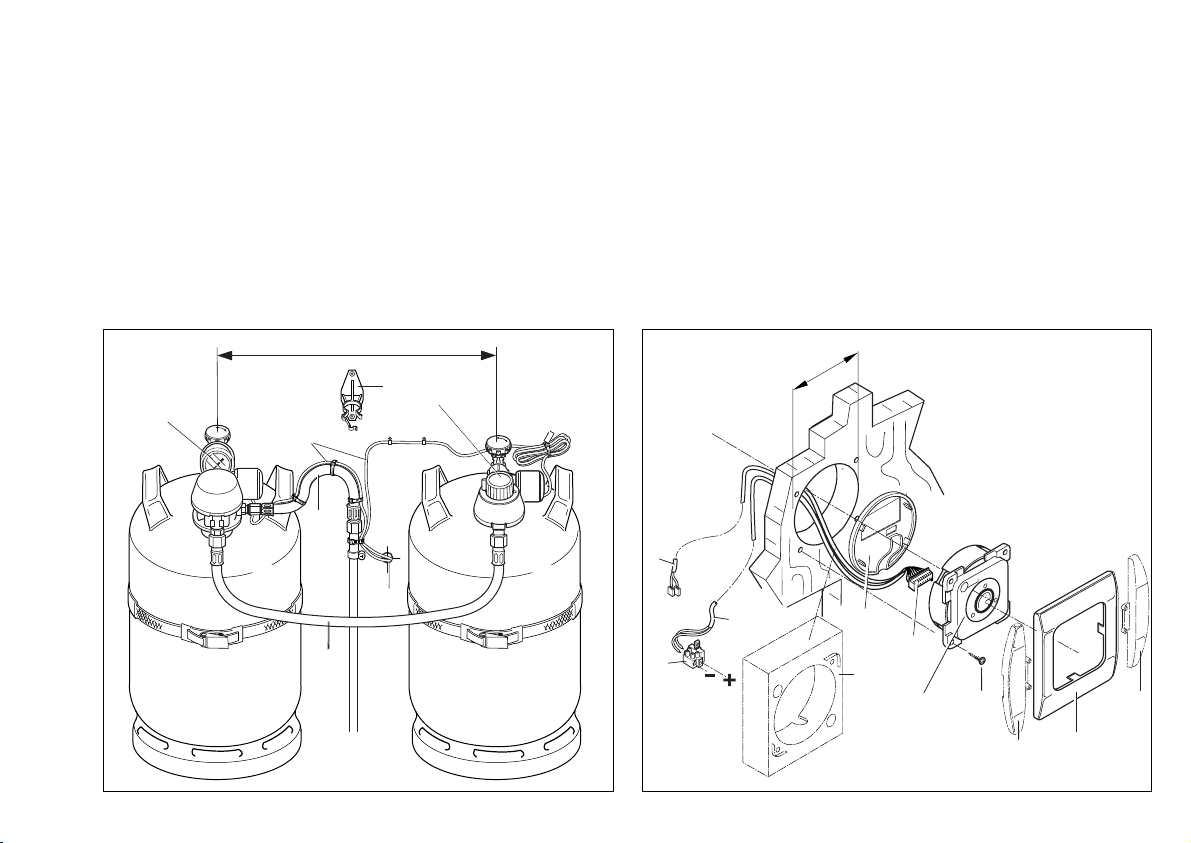
1. Bild A: Zentralregler „A“
und Umschaltregler „B“ so an
die Gasflaschen anschließen,
dass die Schutzkappen nach
Möglichkeit oben sind (Linksgewinde!) – Anschluss nur
von Hand, keine Werkzeuge
verwenden!
2. Vorhandenen Gasschlauch
(3) am Zentralregler „A“
anschrauben.
3. Verbindungsschlauch (4)
an den Reglern „A“ und „B“
anschrauben.
Für die Verbindung der
Regler „A“ und „B“ bei
einem Flaschenabstand von
mehr als 65 cm bietet Truma
einen Ergänzungssatz (Art.Nr. 50020-26900) als Sonderzubehör an.
4. Reglerhalter (14) an geeigneter Stelle an der Fahrzeugwand anbringen.
5. Loch Ø 15 mm für die
Kabeldurchführung (min.
50 cm über dem Boden des
Flaschenkastens) zum Innenraum bohren.
6. Die Regleranschlusskabel
(5) durch die Bohrung (6)
führen und im Flaschenkasten mit Schellen befestigen.
Für die Durchführung (6)
Gummitülle oder Karosseriedichtmittel verwenden.
Die Verbindung der
Anschlusskabel darf
nicht im Flaschenkasten
sein!
7. Bild B: Platz für das Be-
dienteil (7) an gut sichtbarer
Stelle vorsehen (Länge des
Anschlusskabels 6 m) und
ein Loch Ø 55 mm bohren.
Als Einbauzubehör sind
für das Bedienteil (7)
ein Aufputzrahmen (8 – Art.Nr. 40000-52600) und für das
Anschlusskabel (9) eine Verlängerung 5 m (Art.-Nr.
34300-01) erhältlich. Als optischer Abschluss zum Abdeckrahmen (10) sind Seitenteile (11) in verschiedenen
Farben erhältlich.
8. Anschlusskabel (9) am
Bedienteil (7) anstecken und
anschließend die hintere
Abdeckkappe (12) als
Zugentlastung aufsetzen.
9. Das Kabel (9) nach hinten
durch die Bohrung führen
und entsprechend zum Gasflaschenkasten bzw. zur
Zentralelektrik 12 V führen.
10. Bedienteil (7) mit 4
Schrauben (13) befestigen
und Abdeckrahmen (10)
aufstecken.
11. Anschlusskabel (9) mit
den Regleranschlusskabeln
(5) außerhalb des Fla-
schenkastens verbinden
(schwarz mit schwarz und
weiß mit weiß).
Elektrischer
Anschluss 12 V
Zuleitung 12 V (15) mit
beiliegender Sicherung
1A(16) absichern.
(Sicherung bei industrieller
Großverpackung nicht im
Lieferumfang!)
Rot = Plus
Blau = Minus
Page 7

5
Funktionsprüfung
Nach dem Einbau muss die
Dichtigkeit der Duomatic
L Plus mit einem geeigneten
Lecksuchmittel geprüft werden. Die weiterführende Gasanlage muss nach der Druckabfallmethode geprüft werden.
Eine ggfs. vorhandene Prüfbescheinigung (in Deutschland z.B. gemäß DVGW-Arbeitsblatt G 607 Pflicht!)
muss entsprechend ergänzt
werden.
Anschließend gemäß der
Gebrauchsanweisung sämtliche Funktionen des Gerätes
prüfen.
Die Gebrauchsanweisung
ist dem Betreiber auszuhändigen!
Page 8
6
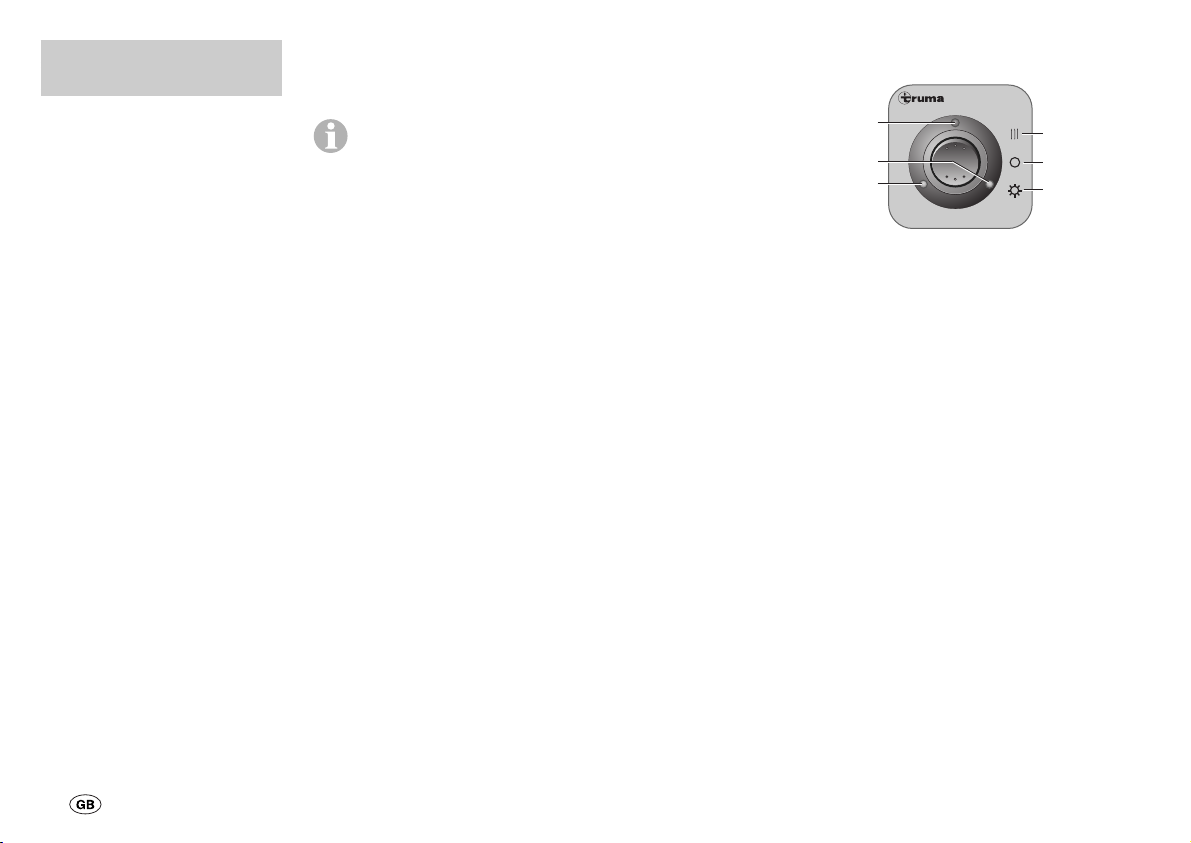
Commissioning
a = On (summer mode)
b = Off
c = On and heating
(winter mode)
d = Equipment-on lamp
e = Indicator lamp A
f = Indicator lamp B
Summer mode:
Switch down (a), equipmenton lamp (d) illuminates.
Indicator lamps A and B illuminate if the gas cylinders
are ready for operation.
Winter mode:
Switch up (c). The equipment-on (d) illuminates and
the gas pressure regulators
are also heated in order to
provide a problem-free gas
supply in winter (power consumption 640 mA). Indicator
lamps A and B illuminate
when the gas cylinders are
ready for operation.
Operating
instructions
The Duomatic L Plus gas
pressure regulator kit consists of a central regulator
„A” and a changeover regulator „B”. This arrangement
provides consistent gas pressure (30 or 50 mbar), irrespective of which cylinder is
supplying the gas.
The indicator lamps on the
remote display in the interior
show whether the gas cylinders are ready for operation.
The rotary knob (1) at
changeover regulator „B” can
be used to control which of
the gas cylinders is the used
or spare cylinder.
If the rotary knob (1) is in the
red area, priority will be given
to obtaining gas from the
cylinder with the central regulator „A”. The gas cylinder
with changeover regulator
„B” then serves as the spare
cylinder. However, if the rotary knob (1) is in the green
area, priority will be given to
obtaining gas from the cylinder with changeover regulator „B” and the gas cylinder
with central regulator „A”
then serves as the spare
cylinder.
Always turn rotary knob
as far as it will go.
The used cylinder will always
be emptied first. The gas
pressure regulator set then
automatically switches to the
previously defined spare
cylinder.
When the remote display is
switched on the relevant indicator lamp („A“ or „B“) goes
off, signalling an empty gas
cylinder.
Important notes
1. Always stand gas cylinders
upright and safeguard from
falling over (particularly 33 kg
cylinders)!
2. The regulators are
equipped with a combination
connector and are suitable
for commercially available
3 kg, 5 kg, 11 kg and 33 kg
gas cylinders.
3. Do not kink gas hoses or
subject to excessive bending!
4. If the gas system is to be operated with one cylinder only
(e.g. in summer), use the central regulator „A”. The rotary
knob (1) on the changeover
regulator „B” must be turned
to the red area. Hook the unused changeover regulator „B”
onto the regulator holder (14)
to prevent it from being
damaged.
5. The pressure gauge (2)
does not indicate how much
gas is in the cylinder, but the
current pressure in the gas
cylinder (depending on ambient temperature). Truma can
supply the Sonatic or Sonatic
Duo ultrasound filling level
measuring device for measuring the contents of the gas
cylinders. Information can be
obtained from your specialist
dealer.
6. Pressure control devices
and hoses must be replaced
with new ones no more than
10 years after their date of
manufacture. This is the responsibility of the operator.
Duomatic L Plus
d
f
e
A
c
b
a
B
Page 9
7
Switching off:
Switch in middle position (b).
Only electrical functions
are switched on and off
using the control panel. The
gas supply itself is mechanically opened and closed at
the gas cylinders. Truma provides a remote gas switch for
shutting off the gas supply
from a central location.
Please seek advice from a
specialist dealer.
Changing cylinders
The gas pressure regulator kit
provides you with a facility
for replacing an empty gas
cylinder without interrupting
consumer operation (equipment is supplied with gas
from spare cylinder).
If an indicator palm goes off
(„A“ or „B“), the relevant gas
cylinder is empty. Close valve
at empty gas cylinder and unscrew regulator from cylinder.
When changing cylin-
ders, do not smoke
and keep away from naked
flames!
After changing an empty
gas cylinder, switch the gas
supply to the other cylinder
by simply turning the rotary
knob (1) by 180°. The previous spare cylinder now becomes the used cylinder. The
new, full gas cylinder is now
available as the spare cylinder.
Leak test
1. Turn all equipment off.
2. Open gas cylinders and
rapid shut-off valves in gas
pipes.
3. Read off pressure at pressure gauge (2) and close gas
cylinders again.
4. If the pressure gauge (2) is
still indicating the same
pressure after 10 minutes,
the gas system is leak-free.
If the pressure drops the
gas system is leaking and
must be repaired by an expert immediately. Do not
open bottle valves again!
This leak test only
provides a rough indication and is not a substitute
for the proper regular gas
test!
Technical data
Voltage: 12 V
Power consumption
Summer mode: 20 mA
Winter mode: 620 mA
Operating pressure
Central regulator:
30 or 50 mbar
Changeover regulator: 100 or
220 mbar (depending on
changeover valve position)
Flow rate: 1.5 kg/h
Regulator outlet
connection:
Outer thread H.4
(corresponds to 1/4“
anticlockwise)
Conformity declaration:
The Truma Duomatic L Plus
gas pressure regulator set
complies with the pressurised equipment directive
97/23/EC, with use of
EN 12864/D and EN 13786/B.
The gas pressure regulator
set is equipped with a safety
valve so that pressures in
excess of 100 mbar cannot
reach the equipment if a fault
occurs.
Product identification
number: CE-0085BN0539
EEC type approval:
e1 022603
Page 10
8
Electrical
connection 12 V
Protect 12 V lead (15)
using provided 1 A
fuse (16). (Fuse not included
in scope of delivery of large
industrial box!)
Red = Plus
Blue = Minus
Function test
After installation, the tightness of the Duomatic L Plus
must be checked using suitable leak-finding equipment.
The rest of the gas system
must be tested using the
pressure drop method.
Any test certificate that is
available (mandatory in
Germany in accordance with
DVGW worksheet G 607, for
example!) must be updated
accordingly.
Then check all equipment
functions as described in the
operating instructions.
The operating instructions
must be handed to the
operator!
Installation
instructions
The operating pressure
of the Duomatic L Plus
(30 or 50 mbar – see printing
on central regulator „A”)
must correspond with the operating pressure of the equipment installed in the vehicle!
Equipment must always
be installed by an expert!
The Duomatic L Plus is only
approved for caravans and
campers where the gas cylinders are placed in the open or
in cupboards that are sealed
from the vehicle interior!
Installation in commercially
used vehicles, closed spaces
(households), mobile homes
(statics) or boats is not permitted.
When using vehicle-specific
or manufacturer-specific control equipment the electrical
connection must be made in
accordance with the Truma
interface description.
1. Figure A: Connect central
regulator „A” and changeover
regulator „B” to gas bottles
with protective caps on top if
possible (anticlockwise
thread!) – Always connect
by hand, do not use tools!
2. Screw existing gas hose (3)
to central regulator „A”.
3. Screw connecting hose (4)
to regulators „A” and „B”.
An extension kit (Art.
no. 50020-26900) is
available from Truma as a
special accessory for connecting regulators „A“ and
„B“ where the cylinders are
more than 65 cm apart.
4. Attach regulator bracket
(14) to wall of vehicle in a
suitable position.
5. Drill hole Ø 15 mm for cable leadthrough (min. 50 cm
above bottom of cylinder
box) to interior.
6. Lead regulator connecting
cable (5) through hole (6)
and attach in cylinder box
using clamps. Use rubber
grommet or body sealant for
leadthrough (6).
The connection to
the connecting cable
must not be in the cylinder
box!
7. Figure B: Make room for
control panel (7) in clearly
visible position (connecting
cable length 6 m) and drill
Ø 55 mm hole.
A surface-type frame
(8 – Art. no. 4000052600 and a 5 m extension
Art. no. 34300-01 for the connecting cable (9) are available
for the control panel (7) as
accessories. Side panels (11)
in different colours are available for finishing off the
covering frame (10).
8. Attach connecting cable
(9) to control panel (7) and
then put rear covering cap on
(12) as a strain reliever.
9. Lead cable (9) towards rear
through hole and lead accordingly to gas cylinder box and
12 V central electrical system.
10. Attach control panel (7)
using 4 screws (13) and fit
covering frame (10).
11. Attach connecting cable
(9) to regulator connecting
cables (5) outside cylinder
box (black to black and white
to white).
Page 11
9
Mode d’emploi
Le kit de détendeurs de gaz
Duomatic L Plus se compose
d’un détendeur central « A »
et d’un détendeur de commutation « B » assurant une
pression de gaz homogène
(30 ou 50 mbars) quelle que
soit la bouteille fournissant le
gaz.
Les lampes-témoins sur le téléaffichage placé à l’intérieur
vous indiquent si les bouteilles de gaz sont prêtes à
fonctionner.
Avec le détendeur de commutation « B », vous pouvez
définir à l’aide du bouton rotatif (1) quelle bouteille doit
être utilisée comme bouteille
de service ou de réserve.
Si, par exemple, le bouton rotatif (1) est situé dans la zone
rouge, le gaz sera d’abord extrait de la bouteille avec le détendeur central « A ». La bouteille de gaz avec le détendeur de commutation « B »
sert alors de bouteille de réserve. Si le bouton rotatif (1)
se situe en revanche dans la
zone verte, le gaz sera à l’inverse d’abord extrait de la
bouteille avec le détendeur
de commutation « B » et la
bouteille de gaz avec le détendeur central « A » servira
de bouteille de réserve.
Toujours tourner le bou-
ton jusqu'à la butée.
La bouteille de service définie
à l’aide du bouton rotatif est
vidée en premier. Le kit de
détendeurs de gaz commute
ensuite automatiquement sur
la bouteille de réserve déterminée au préalable.
Lorsque le téléaffichage est
allumé, la lampe-témoin correspondante (A ou B) s’éteint
et indique que la bouteille de
gaz est vide.
Remarques
importantes
1. Placer toujours les bouteilles de gaz à la verticale et
les protéger contre tout basculement (en particulier les
bouteilles de 33 kg) !
2. Les détendeurs sont équipés d’un raccordement à
combinaison et conviennent
pour les bouteilles de gaz de
3, 5, 11 et 33 kg courantes.
3. Ne pas plier ni fléchir
fortement les tuyaux de gaz !
4. Si l’installation de gaz est
utilisée avec une seule bouteille de gaz (p. ex. en été),
utiliser le détendeur central
« A ». Le bouton rotatif (1) du
détendeur de commutation
« B » doit être tourné dans la
zone rouge. Accrocher le détendeur de commutation « B »
non utilisé sur le support de
détendeur (14) afin de le protéger de tout endommagement.
5. Les manomètres (2) n’indiquent pas le contenu de la
bouteille de gaz mais la pression momentanée dans la
bouteille de gaz (dépendant
de la température ambiante).
Pour mesurer le contenu des
bouteilles de gaz, Truma propose l’instrument de mesure
du niveau de remplissage à
ultrasons Sonatic ou Sonatic
Duo. Veuillez vous informer
dans le commerce spécialisé
à ce sujet.
6. Il incombe à l'exploitant de
remplacer à neuf les détendeurs et conduites de tuyaux
au plus tard 10 ans après leur
date de fabrication. L’exploitant est responsable de cela.
Mise en service
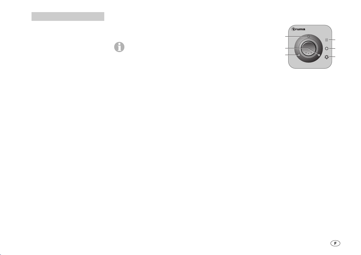
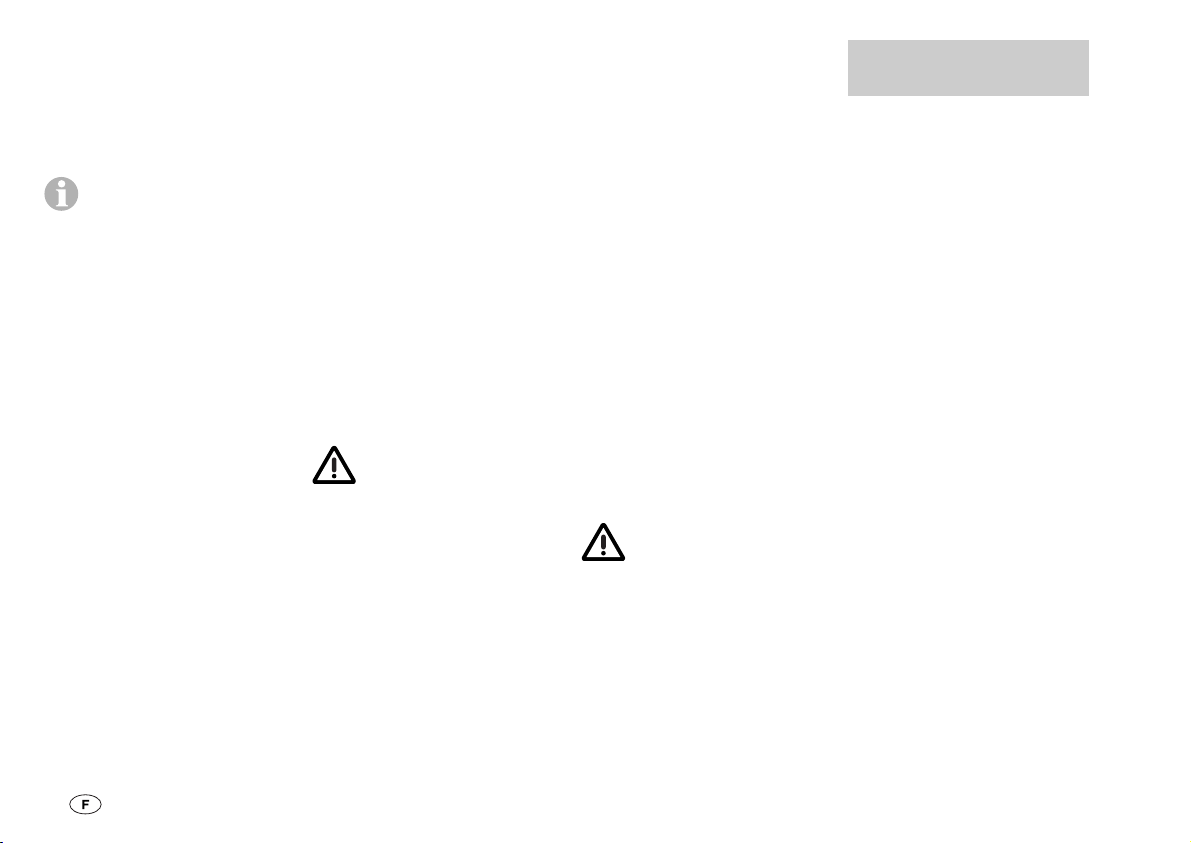
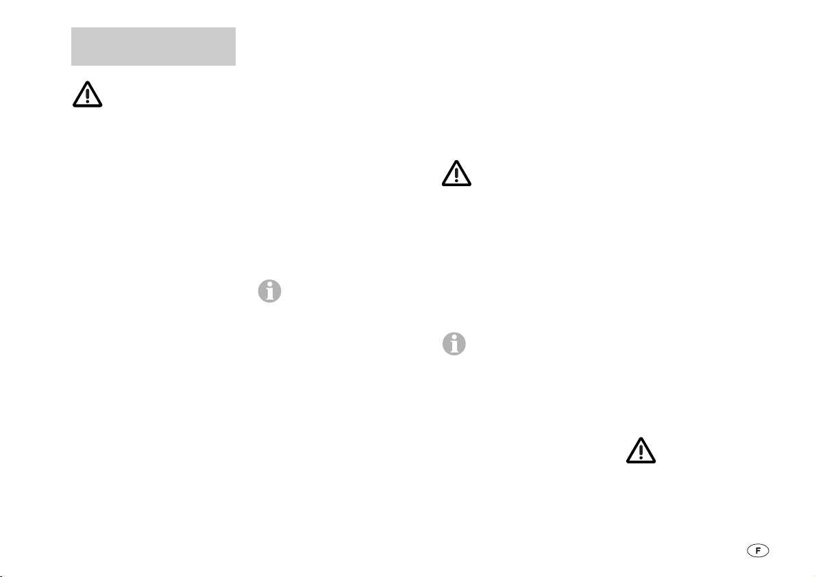
a = On (service été)
b = Off
c = On et chauffage
(service hiver)
d = Affichage du service
e = Lampe-témoin A
f = Lampe-témoin B
Service été :
Le commutateur est vers le
bas (a), l’affichage de service
(d) est allumé. Les lampes-témoins A et B sont allumées si
les bouteilles de gaz sont
prêtes à fonctionner.
Service hiver :
Le commutateur est vers le
haut (c). L’affichage de service (d) est allumé et les détendeurs de pression de gaz
sont chauffés en supplément
afin de garantir une alimentation irréprochable du gaz en
hiver (consommation de courant 640 mA). Les lampes-témoins A et B sont allumées si
Duomatic L Plus
d
f
e
A
c
b
a
B
Page 12
10
Caractéristiques
techniques
Tension : 12 V
Consommation de courant
Service été : 20 mA
Service hiver : 620 mA
Pression de service
Détendeur central :
30 ou 50 mbars
Détendeur de commutation :
100 ou 220 mbars (selon
la position de la valve de
commutation).
Débit : 1,5 kg/h
Raccordement de sortie
détendeur : Filet extérieur H.4
(correspond à 1/4“ gauche).
Déclaration de conformité :
Le kit de détendeurs de gaz
Truma Duomatic L Plus correspond à la directive sur les
appareils à pression 97/23/EG
avec application de
EN 12864/D et EN 13786/B.
Le kit de détendeurs de gaz
est en outre équipé d’une
soupape de sûreté de sorte
qu’il est impossible d’avoir
une pression de plus de
100 mbars sur les appareils
en cas de défaut.
Numéro d’identification du
produit : CE-0085BN0539
Homologation CEE :
e1 022603
les bouteilles de gaz sont
prêtes à fonctionner.
Eteindre :
Commutateur en position
médiane (b).
La pièce de commande
permet uniquement
d’allumer et d’éteindre les
fonctions électriques. L’alimentation en gaz en elle-même est ouverte ou fermée de
façon mécanique sur les bouteilles de gaz. Pour le blocage
central de l’alimentation en
gaz – depuis intérieur –
Truma propose comme accessoire un commutateur de
gaz à distance. Veuillez vous
informer dans le commerce
spécialisé à ce sujet.
Changement de
bouteilles
Le kit de détendeurs de gaz
vous donne la possibilité de
changer une bouteille de gaz
vide sans interrompre le fonctionnement des dispositifs de
consommation (vos appareils
sont alimentés par la bouteille de réserve).
Si une lampe-témoin est
éteinte (A ou B), c’est que la
bouteille de gaz correspondante est vide. Fermer la valve de la bouteille de gaz vide
et dévisser le détendeur de la
bouteille.
Lors du changement
de bouteilles, ne pas
fumer et ne pas avoir de
flamme nue !
Une fois la bouteille de gaz
vide remplacée, il est
conseillé de changer le prélèvement de gaz sur le bouton
rotatif (1) par une simple rotation de 180°. La bouteille de
réserve devient alors la bouteille de service. La nouvelle
bouteille de gaz totalement
remplie est alors disponible
en réserve.
Contrôle des fuites
1. Eteindre tous les appareils.
2. Ouvrir les bouteilles de gaz
et les soupapes à fermeture
rapide dans les conduites de
gaz.
3. Lire la pression sur le manomètre (2) puis refermer les
bouteilles de gaz.
4. Si le manomètre (2) indique toujours la même
pression au bout de 10 minutes, l’installation de gaz est
étanche. Si la pression di-
minue, l’installation de gaz
n’est pas étanche et doit impérativement être remise en
état par un spécialiste.
Ne plus rouvrir les valves
des bouteilles de gaz !
Ce contrôle de fuite
donne uniquement
une idée approximative et ne
remplace aucunement le
contrôle régulier du gaz !
Page 13
11
Instructions de
montage
La pression de service
de Duomatic L Plus
(30 ou 50 mbars – voir étiquette sur le détendeur central « A ») doit correspondre
à la pression de service des
appareils intégrés dans le
véhicule !
Montage uniquement par
un spécialiste !
Duomatic L Plus ne peut être
utilisé que dans les caravanes
et les camping-cars avec mise en place de bouteilles de
gaz à l’extérieur ou dans des
placards hermétiques vis-àvis de l’habitacle!
Le montage dans des véhicules à utilisation professionnelle, dans des locaux fermés
(foyer), dans des mobilehomes ou sur des bateaux
n’est pas admis.
En cas d’utilisation d’unités
de commande spécifiques au
véhicule ou au fabricant, effectuer le raccordement
électrique conformément à
la description d’interfaces
Truma.
1. Fig. A : raccorder le détendeur central « A » et le
détendeur de commutation
« B » aux bouteilles de gaz de
sorte que les couvercles protecteurs se trouvent si possible en haut (filet à gauche !).
– raccordement manuel
uniquement, ne pas
utiliser d’outils !
2. Visser le tuyau de gaz
existant (3) sur le détendeur
central « A ».
3. Visser le tuyau de raccordement (4) sur les détendeurs
« A » et « B ».
Pour la liaison des dé-
tendeurs « A » et « B »
avec une distance entre les
bouteilles de plus de 65 cm,
Truma propose un jeu complémentaire (N° d’art. 50020-
26900) en accessoire spécial.
4. Poser le support de régulateur (14) sur un endroit approprié de la paroi du véhicule.
5. Percer un trou de Ø 15 mm
vers l’intérieur pour le passage de câble (min. 50 cm audessus du fond du caisson de
bouteilles).
6. Faire passer les câbles de
raccordement du détendeur
(5) à travers le trou (6) et les
immobiliser dans le caisson
de bouteilles avec des brides.
Pour le passage (6), utiliser
une douille en caoutchouc ou
un produit d’étanchéité pour
carrosserie.
Le raccord des
câbles de raccordement ne doit pas se
trouver dans le caisson de
bouteilles !
7. Fig. B : prévoir de la place
pour l’unité de commande (7)
à un endroit bien visible (longueur du câble de raccordement 6 m) et percer un trou
de Ø 55 mm.
Un cadre apparent (8)
N° d’art. 40000-52600
pour la pièce de commande
(7) et une rallonge de 5 m
N° d’art. 34300-01 pour le
câble de raccordement sont
disponibles en accessoires.
Des parties latérales (11) sont
disponibles en différentes
couleurs pour la finition
optique du cadre de
recouvrement (10).
8. Enficher le câble de raccordement (9) sur la pièce de
commande (7) et mettre ensuite en place le couvercle de
recouvrement arrière (12)
comme décharge de traction.
9. Faire passer le câble (9)
vers l’arrière à travers l’orifice
et l’amener vers le caisson de
bouteilles de gaz ou le dispositif électrique central 12 V.
10. Fixer la pièce de commande (7) à l’aide de 4 vis
(13) et enficher le cadre de
recouvrement (10).
11. Raccorder le câble de raccordement (9) avec les câbles
de raccordement du détendeur (5) en dehors du cais-
son des bouteilles (noir
avec noir et blanc avec
blanc).
Branchement
électrique 12 V
Protéger la ligne 12 V
(15) avec le fusible 1 A
(16) fourni. (Pour les gros
conditionnements industriels,
fusible non fourni !)
Rouge = Plus
Bleu = Moins
Page 14

12
Contrôle du
fonctionnement
Suite au montage, l’étanchéité du Duomatic L Plus doit
être contrôlée à l’aide d’un
produit de détection de
fuites. Le reste de l’installation de gaz doit être contrôlé
à l’aide de la méthode de la
baisse de pression.
Une éventuelle certification
de contrôle (en Allemagne,
p. ex., conformément à la
fiche de travail DVGW G 607
obligatoire !) doit être
complétée en conséquence.
Contrôler ensuite l’ensemble
des fonctions de l’appareil
conformément au mode
d’emploi.
Remettre le mode d’emploi à la personne utilisant
le système !
Page 15
13
Gebruiksaanwijzing
De gasdrukregelaar-set
Duomatic L Plus bestaat uit
een centrale regelaar „A“ en
een omschakelregelaar „B“.
Deze garanderen een gelijkmatige gasdruk (30 of
50 mbar), onafhankelijk van
het feit welke van de beide
flessen gas levert.
De controlelampen op de in
het interieur aangebrachte afstandsindicatie informeren u
of de gasflessen gereed zijn
voor gebruik.
Op de omschakelregelaar „B“
kunt u met de draaiknop (1)
bepalen, welke van de gasflessen telkens als gebruiksof reservefles gebruikt moet
worden.
Staat b.v. de draaiknop (1) in
het rode bereik, dan wordt in
de eerste plaats gas uit de
fles met de centrale regelaar
„A“ genomen. De gasfles
met de omschakelregelaar
„B“ dient dan als reservefles.
Staat daarentegen de draaiknop (1) in het groene bereik,
dan wordt in de eerste plaats
gas van de fles met de
omschakelregelaar „B“ genomen en de gasfles met centrale regelaar „A“ dient als
reservefles.
Draaiknop altijd tot de
aanslag draaien.
De op de draaiknop vastgelegde gebruiksfles wordt altijd eerst leeggemaakt. De
gasdrukregelaar-set schakelt
dan automatisch om naar de
tevoren vastgelegde
reservefles.
Bij ingeschakelde afstandsindicatie dooft de betreffende
controlelamp (A of B) en
signaleert een lege gasfles.
Belangrijke
aanwijzingen
1. Gasflessen altijd verticaal
zetten en tegen omvallen
beveiligen (met name 33 kgflessen)!
2. De regelaars zijn uitgerust
met een combinatie-aansluiting en zijn geschikt voor in
de handel gebruikelijke 3 kg-,
5 kg-, 11 kg-, en 33 kg-gasflessen.
3. Gasslangen niet knikken of
sterk buigen!
4. Moet de gasinstallatie met
slechts één gasfles (b.v. in de
zomer) gebruikt worden, dan
moet de centrale regelaar „A“
gebruikt worden. De draaiknop (1) op de omschakelregelaar „B“ moet in het rode
bereik gedraaid worden. De
niet gebruikte omschakelregelaar „B“ aan de regelaarhouder (14) hangen, om
deze te beschermen tegen
beschadigingen.
5. De manometers (2) geven
niet de inhoud van de gasfles
aan, maar de momentele (van
de omgevingstemperatuur afhankelijke) druk in de gasfles.
Voor de meting van de inhoud van de gasflessen biedt
Truma de ultrasoon-niveaumeter Sonatic resp. Sonatic
Duo aan. Vraag ernaar bij uw
speciaalzaak.
6. Drukregelapparatuur en
slangleidingen dienen uiterlijk
10 jaar na de fabricagedatum
vervangen te worden door
nieuwe. Hiervoor is de gebruiker verantwoordelijk.
Inbedrijfstelling
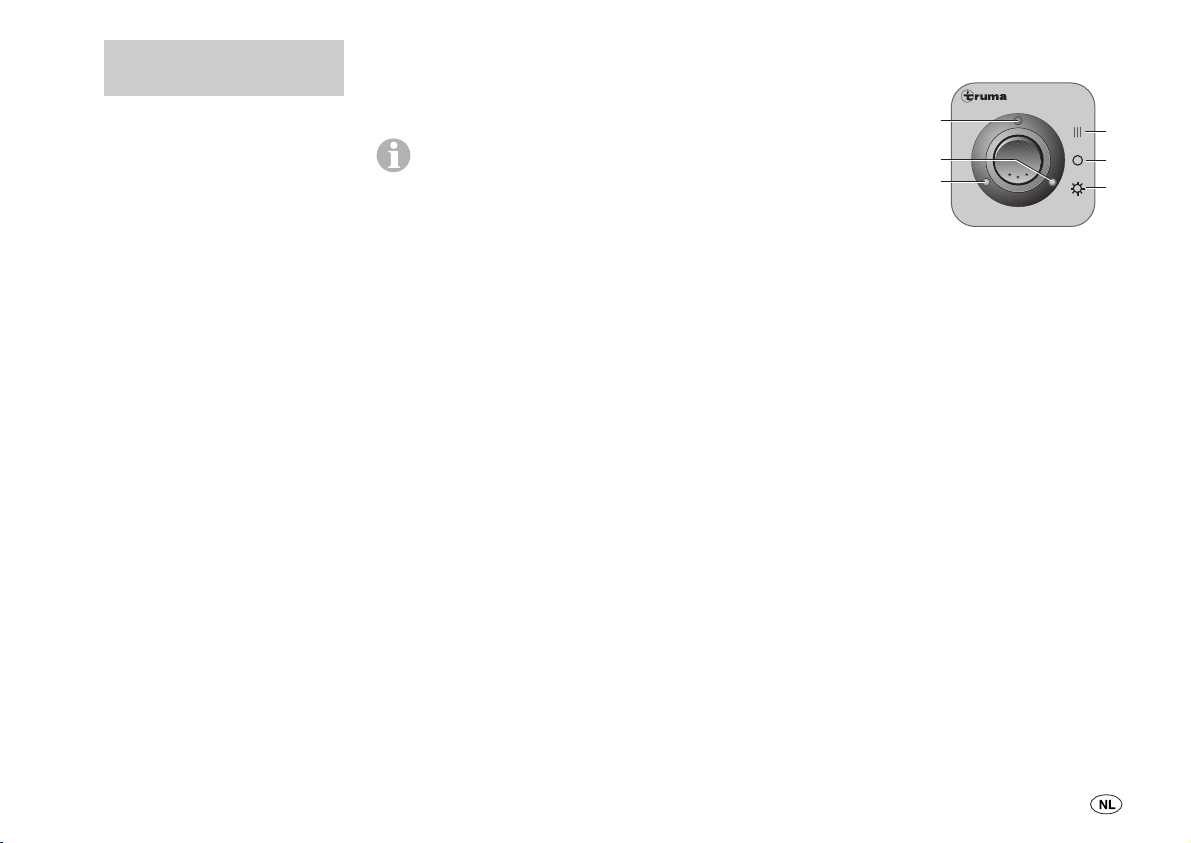
a = aan (zomerstand)
b = uit
c = aan en verwarmen
(winterstand)
d = werkingsindicatie
e = controlelamp A
f = controlelamp B
Zomerstand:
Schakelaar omlaag (a), de
werkingsindicatie (d) brandt.
De controlelampen A en B
branden, wanneer de gasflessen gereed zijn voor gebruik.
Winterstand:
Schakelaar omhoog (c). De
werkingsindicatie (d) brandt
en de gasdrukregelaars worden extra verwarmd, om een
storingvrije gastoevoer in de
winter te waarborgen (opgenomen stroom 640 mA). De
controlelampen A en B branden, wanneer de gasflessen
gereed zijn voor gebruik.
Duomatic L Plus
d
f
e
A
c
b
a
B
Page 16
14
Technische
gegevens
Spanning: 12 V
Opgenomen stroom
zomerstand: 20 mA
winterstand: 620 mA
Werkdruk
centrale regelaar:
30 of 50 mbar
omschakelregelaar:
100 resp. 220 mbar
(afhankelijk van de positie
van de omschakelklep)
Doorstroomhoeveelheid:
1,5 kg/h
Regelaaruitgangsaansluiting:
buitenschroefdraad H.4
(komt overeen met 1/4“ links)
Conformiteitsverklaring:
De Truma gasdrukregelaarset Duomatic L Plus voldoet
aan de drukapparatuur-richtlijn 97/23/EG met gebruikmaking van EN 12864/D en
EN 13786/B. Bovendien is de
gasdrukregelaar-set uitgerust
met een veiligheidsklep, zodat bij een defect geen druk
boven 100 mbar bij de
apparaten kan komen.
Product-ID-nummer:
CE-0085BN0539
EEG-typegoedkeuring:
e1 022603
Uitschakelen:
Schakelaar in middenstand
(b).
Op het bedieningspa-
neel worden alleen de
elektrische functies in- en uitgeschakeld. De gastoevoer
zelf wordt mechanisch op de
gasflessen open- resp. dichtgedraaid. Voor de centrale afsluiting van de gastoevoer
– vanuit het interieur – biedt
Truma een gasafstandsschakelaar als toebehoren aan.
Vraag ernaar bij uw
speciaalzaak.
Flessenwissel
De gasdrukregelaar-set biedt
u de mogelijkheid, een lege
gasfles te vervangen, zonder
de werking van de verbruiksinrichtingen te onderbreken
(uw apparaten worden verder
verzorgd uit de reservefles).
Is een controlelamp (A of B)
uitgegaan, dan is de betreffende gasfles leeg. Ventiel op de
lege gasfles sluiten en regelaar van de fles schroeven.
Bij de flessenwissel
niet roken en geen
open vuur!
Nadat u de lege gasfles gewisseld hebt, moet u bij de
draaiknop (1) met een eenvoudige draai van 180° de
gasafname wisselen. De
voormalige reservefles wordt
nu de gebruiksfles. De nieuwe, volle gasfles staat dan als
reserve ter beschikking.
Lektest
1. Alle apparaten uitzetten.
2. Gasflessen en snelsluitkleppen in de gasleidingen
openen.
3. Druk op manometer (2) aflezen en de gasflessen weer
sluiten.
4. Geeft de manometer (2) na
10 minuten nog steeds de-
zelfde druk aan, dan is de
gasinstallatie dicht. Daalt de
druk, dan is de gasinstallatie
niet dicht en moet onmid-
dellijk door een vakman in orde gebracht worden. Fles-
senventielen niet meer
openen!
Deze lektest geeft
slechts een globaal
overzicht en is geen vervanging voor de regelmatig
terugkerende gascontrole!
Page 17
15
Inbouwhandleiding
De werkdruk van de
Duomatic L Plus
(30 of 50 mbar – zie opdruk
op centrale regelaar „A“)
moet overeenstemmen met
de werkdruk van de in het
voertuig ingebouwde apparaten!
Inbouw uitsluitend door
een vakman!
De Duomatic L Plus is alleen
toegelaten voor caravans en
reisauto‘s met plaatsing van
de gasflessen in de buitenlucht resp. in kasten die t.o.v.
het voertuiginterieur dicht
uitgevoerd!
De inbouw in bedrijfsmatig
gebruikte voertuigen, in gesloten ruimten (huishouden),
in mobiel huis of op boten is
niet toegestaan.
Bij gebruik van voertuigresp. fabrikantspecifieke bedieningsdelen, moet de elektrische aansluiting conform
de Truma-interfacebeschrijving plaatsvinden.
1. Afb. A: Centrale regelaar
„A” en omschakelregelaar
„B” zodanig op de gasflessen
aansluiten, dat indien mogelijk de beschermkappen boven zijn (linksschroefdraad!).
– aansluiting alleen met de
hand, geen gereedschappen gebruiken!
2. Aanwezige gasslang (3)
op de centrale regelaar „A“
schroeven.
3. Verbindingsslang (4) op
de regelaars „A” en „B”
schroeven.
Voor de verbinding van
de regelaars „A” en „B”
bij een flessenafstand van
meer dan 65 cm biedt Truma
een aanvullingsset (art.-nr.
50020-26900) als speciaal
toebehoren aan.
4. Regelaarhouder (14) aanbrengen op geschikte plek op
de voertuigwand.
5. Gat Ø 15 mm boren voor
de kabeldoorvoer (min. 50 cm
boven de bodem van de flessenbak) naar het interieur.
6. De regelaaraansluitkabel
(5) door het gat (6) leiden en
in de flessenbak met klemmen bevestigen. Voor de
doorvoer (6) rubber doorvoerbuisje of carosserie-afdichtingsmiddel gebruiken.
De verbinding van
de aansluitkabels
mag zich niet in de flessenbak bevinden!
7. Afb. B: Plaats voor het be-
dieningsdeel (7) op een goed
zichtbare plek plannen (lengte van de aansluitkabel 6 m)
en een gat Ø 55 mm boren.
Als inbouwtoebehoren
zijn voor het bedieningspaneel (7) een opbouwraampje (8) artikelnr. 40000-52600
en voor de aansluitkabel (9)
een verlengkabel 5 m art.-nr.
34300-01 verkrijgbaar. Bij het
afdekraampje (10) zijn zijdelen (11) in verschillende kleuren verkrijgbaar voor een
optisch mooie afwerking.
8. Aansluitkabel (9) op het
bedieningspaneel (7) steken
en vervolgens de achterste
afdekkap (12) als trekontlasting aanbrengen.
9. De kabel (9) naar achteren
door het gat leiden en dienovereenkomstig naar de gasflessenbak resp. naar de
centrale elektrische installatie
12 V leiden.
10. Bedieningspaneel (7) met
4 schroeven (13) bevestigen
en afdekraampje (10) erop
steken.
11. Aansluitkabel (9) met de
regelaaraansluitkabels (5)
buiten de flessenbak verbinden (zwart met zwart en
wit met wit).
Elektrische
aansluiting 12 V
Toevoerleiding 12 V
(15) beveiligen met bij-
gevoegde zekering 1 A (16).
(Zekering bij industriële
grootverpakking niet bij de
levering inbegrepen!)
rood = plus
blauw= min
Page 18

16
Functiecontrole
Na de inbouw moet de dichtheid van de Duomatic L Plus
met een geschikt lekdetectiemiddel gecontroleerd worden. De verder gaande gasinstallatie moet volgens de
drukverminderingsmethode
gecontroleerd worden.
Een evt. aanwezig keuringscertificaat (in Duitsland b.v.
conform DVGW-werkblad
G 607 verplicht!) moet dienovereenkomstig aangevuld
worden.
Vervolgens conform de gebruiksaanwijzing alle functies
van het apparaat controleren.
De gebruiksaanwijzing
moet aan de gebruiker
overhandigd worden!
 Loading...