

Page 1
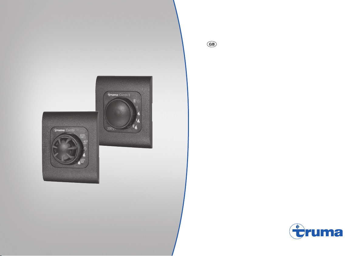
Truma CP (E) classic
Operating instructions Page 2
To be kept in the vehicle!
Page 2
CP (E) classic control panels
Table of contents
Symbols used ........................................................................ 2
Intended use ....................................................................... 2
Operating instructions
Safety instructions ............................................................ 3
Display and control elements .......................................... 3
CP classiccontrol panel ......................................................... 3
CP E classic power selector switch ...................................... 3
Start-up ................................................................................ 4
Hot water mode .................................................................... 4
Heating mode ........................................................................ 4
Switching off ...................................................................... 5
Fault ...................................................................................... 5
Gas or diesel mode ............................................................... 5
Electric mode ........................................................................ 5
Mixed mode .......................................................................... 6
Accessories ......................................................................... 6
Troubleshooting guide (Combi Gas heater) ................... 7
Troubleshooting guide (Combi Diesel heater) .............. 9
Technical data ................................................................... 11
Maintenance ..................................................................... 11
Disposal ............................................................................. 11
Symbols used
The appliance must only be installed and repaired
by an expert.
Note containing information and tips.
Observe the ESD regulations! Electrostatic charging
can destroy the electronics. Ensure that potential com-
pensation is present before touching the electronics.
Intended use
CP classic control panel
The control panel can be used to adjust the room and water
temperature on a Truma Combi (E) heater.
CP E classic power selector switch
(Combi Diesel E only)
The power selector switch can be used to select between
the power types diesel and / or electrical power on a
TrumaCombi Diesel E heater (with heating elements for
electric mode). The CP classic control panel is also required.
The control panels are intended for installation in caravans
and motor homes. Installation in boats is not permitted.
2
Page 3
Operating instructions
Safety instructions
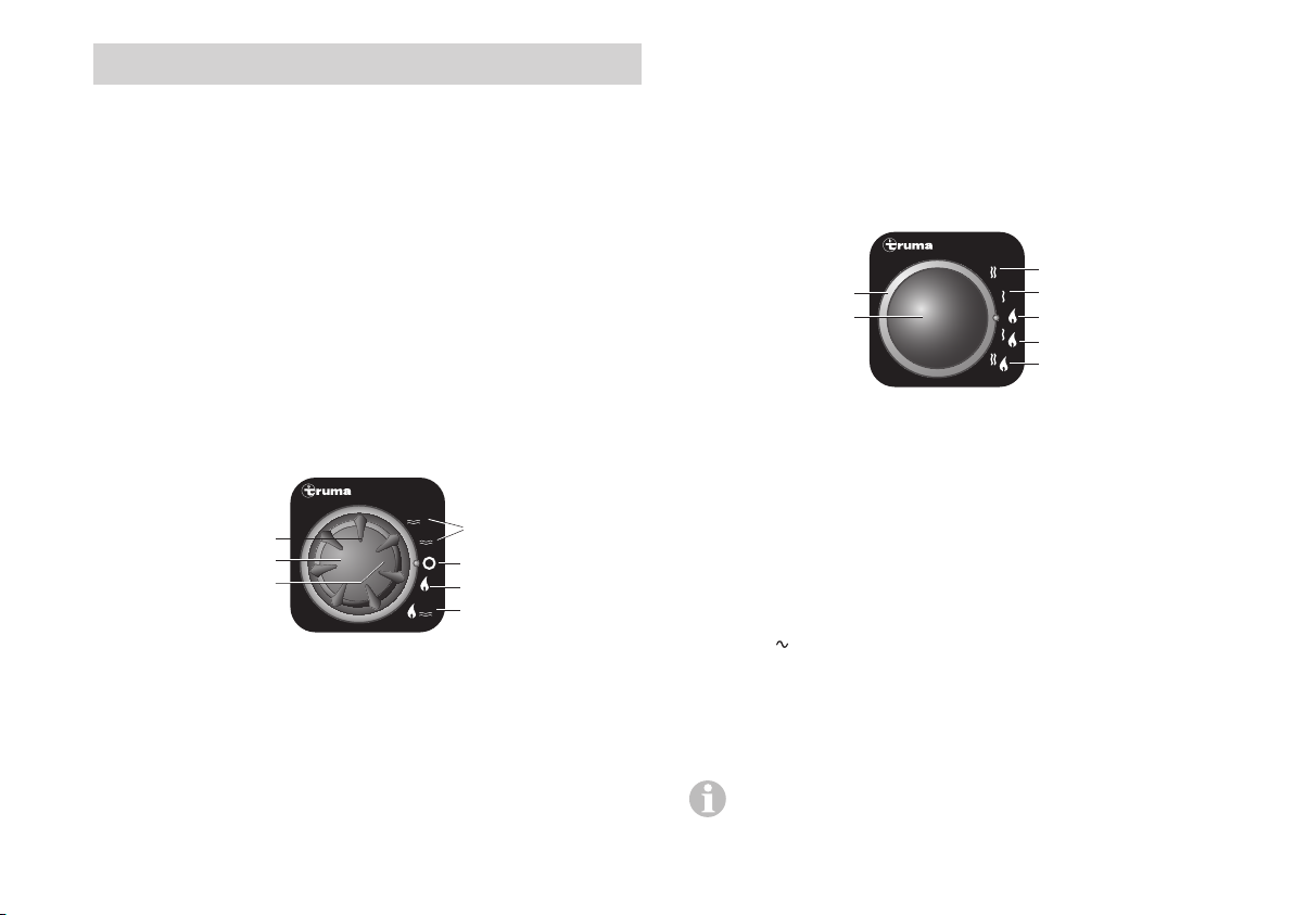
f = Rotary switch “Off”
g = Yellow LED lit, “Boiler heat-up phase”,
yellow LED flashing “Warning”
r = Red LED lit, red LED flashing “Fault”
– The heater or control panel must not be used unless it is in
perfect working order.
– Repairs must be carried out immediately. Only carry out
repairs yourself if the solution is described in the troubleshooting guide of this operating instructions.
– Do not make repairs or modifications to the heater or the
control panel!
– A defective heater or defective control panel may only be
repaired by the manufacturer or his service department.
Display and control elements
CP classiccontrol panel
Combi
°
60
7
5
a
g, h
b
3
2
4
9
3
1
5
1
a = Control knob for room temperature (1 – 5)
b = Green LED lit, “On”
c = Hot water mode
(Water temperature 40 °C or 60 °C)
d = Heating mode
(heating without water temperature monitoring or with
drained water system)
e = Heating mode
(heating with water temperature monitoring)
c
°
40
f
d
°
60
e
CP E classic power selector switch
(Combi Diesel E only)
Combi E
j
i
o
230 V~
i = Power selection rotary switch
j = Electric mode 230 V, 1800 W
k = Electric mode 230 V, 900 W
l = Diesel mode
m = Mixed mode* (diesel or electric mode 900 W)
m = Mixed mode* (diesel and electric mode 1800 W)
o = Yellow LED lit “Electric mode”
* Hot water mode
In hot water mode, the heater automatically selects electric
mode with the preset electric power of 900 W or 1800 W. If
the 230 V power supply is disconnected or fails, the heater automatically switches over to diesel mode.
Heating mode:
Electric mode has priority in heating mode. If the electrical
heating output is insufficient, diesel mode is enabled.
Switching on the electric heating elements as well
does not increase the maximum heating power.
k
l
m
n
3
Page 4

Start-up
Heating mode
Heating mode is possible with or without water
content depending on the operating mode.
Hot water mode
This operating mode can only be used if the boiler has
been filled.
Appliances with electrical heating elements
Select diesel or electric mode using the power selector switch.
Illumination of the yellow LED (o) at the power selector switch
indicates that the appliance is operating with 230 V .
Mixed mode (diesel and electric mode) is not possible
in hot water mode. With this setting, the appliance automatically selects electric mode with the preset operating
level of 900 W or 1800 W. If the 230 V power supply is
disconnected or fails, the heater automatically switches
over to diesel mode.
Move the rotary switch on the control panel to position (c –
hot water mode) 40 °C or 60 °C. The green (b) and yellow (g)
LEDs light up.
After reaching the set water temperature (40 °C or 60 °C),
the heater will switch off and the yellow LED (g) will be
extinguished.
Appliances with electrical heating elements
Select diesel, electric or mixed mode using the power
selector switch. Illumination of the yellow LED (o) at the
power selector switch indicates that the appliance is
operating with 230 V .
– Heating with water temperature monitoring
Move rotary switch on control panel to “On” position (e).
Set the control knob (a) to the desired thermostat setting (1 – 5).
The green LED (b) for operation is lit and simultaneously indicates the position of the selected room temperature. The
yellow LED (g) indicates the water‘s heat-up phase.
The appliance automatically selects the required operating level
according to the temperature difference between the setting
on the control panel and the current room temperature. After
the room temperature set on the control panel is reached, the
heater switches back to the lowest setting and heats the water
content to 60 °C. After the water temperature is reached, the
heater switches itself off and the yellow LED(g) goes out.
– Heating without water temperature monitoring
Move rotary switch on control panel to “On” position (d).
Set the control knob (a) to the desired thermostat setting (1 – 5).
The green LED (b) for operation is lit and simultaneously indicates the position of the selected room temperature. The
yellow LED (g – water heat-up phase) will be lit only when the
water temperature is below 5 °C!
4
Page 5

The appliance automatically selects the required operating
level according to the temperature difference between the setting on the control panel and the current room temperature.
Once the room temperature selected on the control panel has
been reached, the heater switches off. The warm air fan will
continue to run at a low speed as long as the blow-out temperature (on the appliance) is higher than 40 °C.
If the boiler has been filled, the water is automatically heated
as well. The water temperature then depends on the heat output and the time taken to reach the set room temperature.
– Heating with drained water system
Appliances with gas mode
If the appliance is not going to be used for a long period of
time, close the quick-acting valve in the gas supply line and
turn off the gas cylinder.
Fault
Gas or diesel mode
In the event of a fault the red LED (h) or the yellow LED (g) on
the control panel will flash.
Move rotary switch on control panel to “On” position (d).
Set the control knob (a) to the desired thermostat setting (1 – 5).
The green LED (b) for operation is lit and simultaneously indicates the position of the selected room temperature. The yellow LED (g) will only be lit if the temperature of the appliance
is below 5 °C!
Depending on the operating mode, the appliance will automatically select the required operating level according to the
temperature difference between the setting on the control
panel and the current room temperature. Once the room temperature selected on the control panel has been reached, the
heater switches off. The warm air fan will continue to run at a
low speed as long as the blow-out temperature (on the appliance) is higher than 40 °C.
Switching off
Switch off heater at control panel using rotary switch (position f).
The green LED (b) goes off.
Always drain water contents if there is a risk of frost!
Refer to the troubleshooting guide for possible causes.
A reset (fault reset) is carried out by switching off – waiting
until all LED’s on the control panel have stopped flashing –
and then switching the heater on again.
If the window to which a window switch is mounted is
opened, the heater stops operating and the yellow LED (g)
flashes 3 times. The heater continues operating when the window is closed.
Electric mode
(Combi Diesel E only)
The yellow LED (o) goes off on the power selector switch, and
the yellow LED (g) or the red LED (h) flashes on the control panel.
Refer to the troubleshooting guide for possible causes.
If, during operation, the 230 V voltage supply is inter-
rupted only briefly (approx. 1 second), the heater then
continues in electric mode.
5
Page 6
Mixed mode
(Combi Diesel E only)
Fault in the 230 V power supply
The yellow LED (o) on the power selector switch goes off and
the yellow LED (g) on the control panel flashes 2 x.
Refer to the troubleshooting guide for possible causes.
If the 230 V power supply is interrupted during mixed mode,
the heater will automatically switch to diesel mode. As soon
as the 230 V power supply has been restored, the heater
automatically switches back to mixed mode.
Fault in the combustion procedure
The yellow LED (o) on the power selector switch illuminates
and the red LED (h) or the yellow LED (g) on the control panel
flashes.
Refer to the troubleshooting guide for possible causes.
If the flame goes out during mixed mode (e.g. empty gas cylinder
or closed exhaust outlet), the heater automatically switches
to electric mode. For the heater to operate in mixed mode
again, the cause of the fault must be remedied and the heater
switched off and on again at the control panel (faultreset).
Accessories
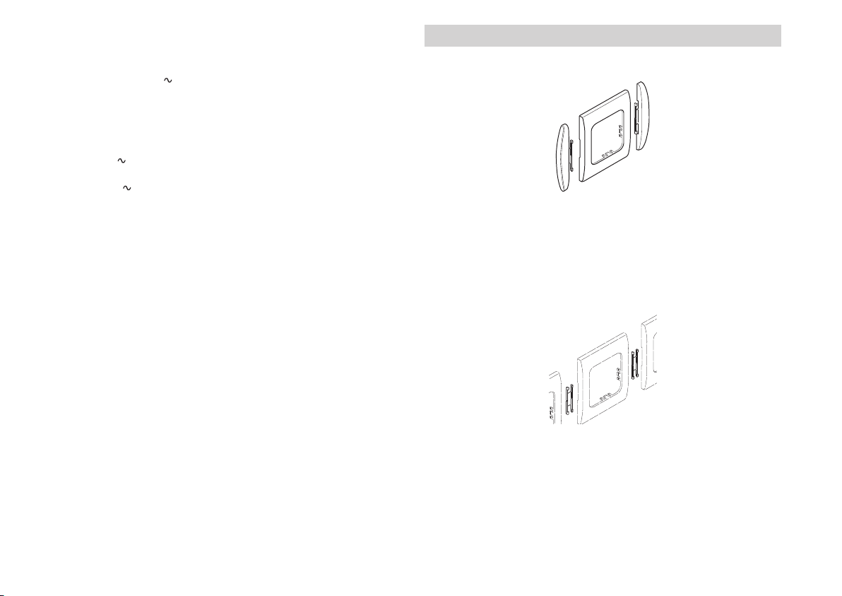
Cover frames are available as accessories.
For the visual finish, side parts are available to match the
cover frame. Please contact your specialist dealer in this
connection.
Line-up clip, 1 pc. (part no. 34000-65900) for connecting two
cover frames.
Other accessories (without picture) for control panel:
– Control panel cable in various lengths (maximum 10 m)
6
Page 7

Troubleshooting guide (Combi Gas heater)
Flashing code at the analogue CP classic control panel
Flash sequence LED:
– On / Off: 0.5 seconds
Pause between flash sequence: 5 seconds
Fault Cause Remedy
No LED is on, the appliance is
switched on and is supplied with operating voltage
No LED illuminates after switching on – No operating voltage
The green LED illuminates when
the appliance is switched on, but
the heater does not operate
After switching on the heater, the
green LED illuminates and the
yellow LED flashes 1 x
(heater continues operating)
yellow LED flashes 2 x
(heater not functioning)
yellow LED flashes 3 x
– Automatic restart is blocked, e.g.
after a power failure.
– Appliance fuse or vehicle fuse
defective
– The temperature setting on the con-
trol panel is lower than the room
temperature
– Risk of low voltage
Battery voltage too low
< 10.4 V
– Low voltage
Battery voltage too low
< 10.0 V
– Overvoltage > 16.4 V – Check battery voltage and voltage sources such as
– Open window above cowl
(window switch)
– Reset (fault reset) by switching off, waiting 5 seconds and
then switching on again
– Check 12 V battery voltage, charge battery if necessary
– Check all electrical plug connections
– Check fuse of appliance or vehicle and replace if necessary
(see fuses)
– Select higher room temperature at the control panel
– Charge battery
– Charge battery. If necessary replace old battery
the charger
– Close window
7
Page 8

Fault Cause Remedy
yellow LED flashes 4 x
(after operating for a longer period of
time, the heater switches to failure)
yellow LED flashes 5 x – Room temperature sensor or cable faulty – Contact Truma Service
yellow LED flashes 7 x – Control panel or control panel cable
yellow LED flashes 8 x – FrostControl heating element has a
yellow LED flashes 9 x
(approx. 30 seconds after switching
on the heater)
(after operating for a longer period of
time, the heater switches to failure)
Red LED flashes 1 – 8 times – Heater fault – Please contact Truma Service.
Green LED still illuminated after
the heater has been switched off
Room heating does not react to
adjustment immediately
After switching on the green and
the red LED illuminate
– Summer mode with empty water
container
– Warm air outlets blocked – Check the individual outlet openings
– Circulated air intake blocked – Remove the circulated air intake blockage
defective
short circuit
– Gas cylinder or quick-acting valve in
the gas supply line closed
– Gas cylinder empty – Replacing a gas cylinder
– Gas pressure regulation system iced up – Use regulator heater (EisEx)
– Butane content in the gas cylinder too
high
– After-running is active to reduce the
temperature of the appliance
– After-running is active to reduce the
temperature of the appliance
– Faulty electronics – Contact Truma Service
– Switch appliance off and allow to cool,
fill boiler with water
– Contact Truma Service
– Disconnect heating element plug from electronic control
unit, replace heating element
– Check gas supply and open valves
– Use propane (butane is unsuitable for heating, particularly
at temperatures below 10°C)
Determine the flashing code (short, long) if necessary:
red LED on heater electronics.
– No fault. After-run switches itself off after max. 5 minutes
– No fault. After-run switches itself off after max. 5 minutes
If these actions do not remedy the problem, please contact Truma Service.
8
Page 9

Troubleshooting guide (Combi Diesel heater)
Flashing code at the analogue CP classic control panel
Flash sequence LED:
– On / Off: 0.5 seconds
Pause between flash sequence: 5 seconds
Fault Cause Remedy
No LED illuminates after
switching on
The green LED illuminates when
the appliance is switched on, but
the heater does not operate
Green LED flashes (with 5 Hz) after
the heater has been switched off
Red LED flashes 6 x – Lack of fuel due to insufficient fuel
Red LED flashes (except 6 times)
or red LED permanently on
Yellow LED flashes 1 x – Risk of low voltage
Yellow LED flashes 2 x – Undervoltage < 10.2 V – Check battery voltage, charge if necessary
Yellow LED flashes 2 x – Overvoltage > 16.4 V – Check battery voltage and voltage sources such as
– No operating voltage
– Appliance fuse or vehicle fuse
defective
– The temperature setting on the
control panel is lower than the
room temperature
– After-running is active to re-
duce the temperature of the
appliance
tank filling, tank has run empty
and / or vehicle is on a slope
– Heater malfunction – Contact Truma Service
< 11.5 V
– Check 12 V battery voltage, charge battery if necessary
– Check all electrical plug connections
– Check fuse of appliance or vehicle, replace if necessary (see fuses)
– Select higher room temperature at the control panel
– No fault, after-run switches itself off after max. 5 minutes
– Fill tank with fuel, then fill fuel line as described in “Initial start-up”
– Use the electrical power from the battery sparingly,
e.g. restrict lighting
– Charge battery
– Short-term immediate action, switch off major consumers
or start up vehicle engine until the heater starts running
(approx. 4 minutes)
– Battery capacity inadequate, if necessary exchange old battery
the charger
9
Page 10
Fault Cause Remedy
(only on Combi D 6 E) – No 230 V operating voltage
– 230 V fuse defective
– Longer period of non-use, e.g.
over the winter months
– Overheating protection has
been triggered
Yellow LED flashes 3 x – Open window above cowl
(window switch)
Yellow LED flashes 4 x – Warm air temperature and / or
water temperature exceeded:
– Not all warm air ducts are
connected
– Warm air outlets blocked
– Circulated air intake blocked
– Summer mode with empty
water container
Yellow LED flashes 5 x – Room temperature sensor or
cable defective
Yellow LED flashes 6 x – Water temperature exceeded in
summer mode
Yellow LED flashes 7 x – Control panel or control panel
cable defective
Yellow LED flashes 8 x – FrostControl heating element
has a short circuit
– Restore 230 V operating voltage
– Replace 230 V fuse
– Operate the heater in diesel mode for approx. 30 minutes – then
switch over to electric mode
– Reset the overheating protection, allow the heater to cool, remove
the connection cover and press the reset button
– Close windows
– Check whether the 4 warm air ducts are connected
– Check the individual outlet openings
– Remove the circulated air intake blockage
– Fill boiler with water
– Contact Truma Service
– Fill boiler with water
– Contact Truma Service
– Disconnect heating element plug from electronic control unit,
replace heating element
If these actions do not remedy the problem, please contact Truma Service.
10
Page 11
Technical data
Dimensions (LxWxH) 53 x 53 x 44 mm
Subject to technical changes.
Maintenance
The control panels are maintenance free.
Disposal
The appliance must be disposed of in accordance with the administrative regulations of the respective country in which it is
used. National regulations and laws (in Germany, for example,
the End-of-life Vehicle Regulation) must be observed.
11
Page 12

Should problems occur, please contact the Truma Service
Centre or one of our authorised service partners
(see www.truma.com).
In order to avoid delays, please have the unit model and serial
number ready (see type plate).
©
34020-00439 · 00 ·07/2017 ·
Truma Gerätetechnik GmbH & Co. KG
Wernher-von-Braun-Straße 12
85640 Putzbrunn
Deutschland
Service
Telefon +49 (0)89 4617-2020
Telefax +49 (0)89 4617-2159
[email protected]
www.truma.com
 Loading...