

Truma Combi eco, Combi eco plus, Combi comfort, Combi comfort plus Operating Instructions Manual
Page 1

*
Truma Combi®
LP Gas Furnace with Supplementary Indirect Water Heating
Operating instructions
FIRE OR EXPLOSION HAZARD
Failure to follow safety warnings exactly
could result in serious injury, death or
property damage.
Do not store or use gasoline or other
flammable vapors and liquids in the vicinity of this or any other appliance.
WHAT TO DO IF YOU SMELL GAS
• Evacuate all persons from the vehicle.
• Shut off the gas supply at the gas container or source.
• Do not touch any electrical switch, or use
any phone or radio in the vehicle.
• Do not start the vehicle’s engine or electric
generator.
• Contact the nearest gas supplier or certified service technician for repairs.
• If you cannot reach a gas supplier or certified service technician, contact the nearest
fire department.
• Do not turn on the gas supply until gas
leaks have been repaired.
To be kept in the vehicle.
This document is part of the furnace.
Conforms to ANSI Std. Z21.47
Certified to CSA Std. 2.3
4010007
* Patent
Pending
Installation and service must be performed by
a qualified installer, service agency, or the gas
supplier.
Page 2

Table of Contents
Trademark information ........................................................ 2
Intended use .......................................................................... 2
Prohibited use ........................................................................ 2
Mounting arrangement / Accessories ................................ 3
Furnace diagram .................................................................... 4
California Proposition 65 lists chemical sub-
stances known to the state to cause cancer,
birth defects, death, serious illness or other reproductive harm. This product may contain such
substances, be their origin from fuel combustion (gas) or components of the product itself.
Consumer Safety Information
Safety symbols and signal words ...................................... 6
Safety behavior and practices ............................................. 6
Safety features ...................................................................... 8
Operating Instructions
How the Combi furnace works ........................................... 8
Selectable modes of operation ................................................. 9
Selectable modes of power input ............................................. 9
Switch for gas shut-off valve .............................................. 9
Room temperature sensor ................................................. 10
Truma pressure relief/drain valve ..................................... 10
Opening the Truma pressure relief/drain valve ....................... 10
Closing the Truma pressure relief/drain valve ........................ 10
Starting the Combi furnace ............................................... 11
Inspections before each use .................................................. 11
Filling the water container ...................................................... 11
Switching on the furnace ....................................................... 12
Shutdown ............................................................................. 12
Switching off the furnace ....................................................... 12
Draining the water container .................................................. 13
Winterizing ........................................................................... 13
Optional: Winterizing the RV with a winterizing fluid ............. 13
Winter operation ................................................................. 13
Combi Technical Data ........................................................ 14
“ Combi” MANUFACTURER’S LIMITED WARRANTY .... 15
Maintenance and service ................................................... 16
Decalcifying and cleaning the water container ...................... 16
Truma pressure relief/drain valve ........................................... 17
Replacing the 12-volt fuse ...................................................... 17
Troubleshooting .................................................................. 18
Appendix ............................................................................... 19
Trademark information
Truma Combi® referred to as Combi below.
Intended use
The Combi LP gas furnace* with supplementary indirect water heating may be used only in
recreational vehicles (RVs) for heating the room
and the faucet water.
Recreational vehicles (RVs) are designed as
temporary living quarters for recreation, travel
and/or camping. RVs have their own power or
are towed by another vehicle.
*Models
• Combi eco
• Combi eco plus
• Combi comfort
• Combi comfort plus
The Combi eco plus and Combi comfort plus
furnaces also feature electrical heating elements
for a supply voltage of 120 V.
Prohibited use
Any use other than the intended use (see above)
is prohibited.
Examples of prohibited use:
• Use in a marine environment.
• Use as part of a space heating system.
• Use in mobile homes.
• Use in food trucks or roadside food vending
vehicles.
• Use in construction trailers.
2
Page 3

Mounting arrangement / Accessories
This is a typical installation for illustration. The installation in your vehicle may vary.
The illustration is not to scale.
B
C
I
Fig. 1
H
7
0
D
A
G
F
K
J
E
Legend
A Combi furnace
B CPplus control panel
C Room temperature sensor
D Opening for circulated air intake
(with mounted grid (optional))
E Truma pressure relief/drain valve
F Wall cowl with exhaust venting system
(tube in tube)
G Warm air ducts with insulation sleeve
H Warm air end outlet with air throttle
I Wall outlet vent
J Non-return valve (optional)
K Truma water pressure regulator (optional)
3
Page 4

Furnace diagram
14
12
1 (top)
4
32
5
18
6
Fig. 2
17
16
15
10
7
8
13
5
19
20b
4
20a
11
1 (top)
10
9
Fig. 3
4
3
11
2
6
7
10
18
6
7
9
19
9
8
Page 5

Key
1 Combi furnace with supplementary indi-
rect water heating
2 Connection for combustion air supply
tube
3 Connection for exhaust tube
4 Switch for gas shut-off valve
5 Connection cover
6 Warm air outlets (upper)
7 Warm air outlets (lower)
8 3-pole 120 volt electrical plug
(only on Combi eco plus and
Combi comfort plus models)
9 Plastic frame feet
10 Aluminum frame feet
11 Circulated air fan
12 Fan for combustion air
13 Cold water connection (inlet)
14 Hot water connection (outlet)
15 Gas shut-off valve (behind the cover)
16 Gas connection (inlet)
17 Test connection (gas) (behind the cover)
18 Electronics housing cover
19 Recessed grips
20a Original type plate
20b Duplicate type plate
5
Page 6

Consumer Safety Information
Safety symbols and signal words
This is the safety alert symbol. This symbol
alerts you to potential hazards that can kill or
hurt you and others.
• Keep the area around the Combi furnace free
from combustible materials, gasoline, and
other flammable vapors or liquids such as
pressurized dispensers or wax candles.
• Keep the area in front of the warm air outlets
(Fig.1 – H) free of combustible or heat-sensitive materials. Do not put any material into
the warm air outlets.
indicates a hazardous situation
which, if not avoided, will result in death or
serious injury.
indicates a hazardous situation
which, if not avoided, could result in death or
serious injury.
indicates a hazardous situation
which, if not avoided, could result in minor or
moderate injury.
is used to address practices not
related to physical injury.
Other important information or tips
Safety behavior and practices
Ensuring a safe operating environment
• Danger of suffocation! To ensure dis-
sipation of exhaust gases, operate the
Combi furnace outdoors only.
– Never use in enclosed spaces or tents or
breathe in the exhaust gases.
– If installing an airtight awning, make sure
that the exhaust system terminates to the
outdoors.
– If the RV is parked in an enclosed space:
– Block the flow of fuel to the Combi
furnace.
– Deactivate the time switch.
– Switch off the Combi furnace at the con-
trol panel.
– Ensure that the Combi furnace cannot be
switched on through the Truma App un-
der any circumstances.
• Use the Combi furnace only with a functional LP gas and carbon monoxide detector
installed in the RV. For installation, operation
and function test follow the manufacturer’s
guidelines.
• In order to avoid overheating of the Combi
furnace, keep the air inlets of the Combi
furnace (Fig.2 – 11), the air openings to the
area in which the Combifurnace is installed
(Fig.1 – D) and the spacing around the
Combi furnace free of obstruction.
• To ensure clean combustion, keep the wall
cowl free of obstruction. Do not lean any objects against the wall cowl (Fig.1 – F).
• Danger of hot surfaces. The temperature of
the exhaust gases can reach 320°F (160°C).
Do not touch the area around the wall cowl
and do not lean any objects against the wall
cowl or the RV.
Responsibilities of the operator
• The operator is responsible for the water filled
into the Combi water container and its quality.
• The operator is responsible for protecting the
Combi furnace against freezing.
Safe operation
• Use with LP gas (propane) only. Butane or
any mixtures containing more than 10% of
butane must not be used.
– LPG tanks must be filled by a qualified gas
supplier only.
• Danger of damage to the gas system! For
the operation of gas pressure regulation systems, gas-burning devices or gas systems
only gas cylinders that supply gas in the
gaseous phase may be used. Gas cylinders
which supply gas in the liquid phase are
prohibited.
• Ensure that the interior of the RV is sufficiently vented. The Combi furnace might
briefly emit smoke and an odor because of
dust or dirt when it is switched on, especially
if it has not been used in a long time.
– For using the Combi furnace in hot water
mode (140°F (60°C)), let it heat up several
times.
6
Page 7

• Hot air can be dangerous, especially for infants, children, the elderly, or infirm. It can
cause burns:
– Ventilation air can reach 250°F (121°C) at
the warm air outlets. Always check the air
temperature before varying the air throttle
position (Fig.1 – H).
• Hot water can be dangerous, especially for
infants, children, the elderly, or infirm. It can
cause severe burns:
– Never actuate the pressure relief/drain
valve (Fig.1 – E) as long as the Combi furnace is under water pressure and/or still
hot.
– Always check the water temperature be-
fore entering a shower or bath.
Safe handling of malfunctions
• Switch OFF the gas supply and the Combi
furnace if anything seems to be out of the
ordinary.
• Danger of fire or explosion when attempting
to use a flood-damaged Combi furnace or
if the RV has been involved in an accident!
A qualified service technician must inspect
the furnace. In the case of moisture damage,
the qualified service technician must replace
damaged gas controls, control system parts
and/or electrical parts, or provide a new
furnace.
• Only a qualified service technician may perform repairs.
• How long before hot water causes skin
damage?
Temperature
°F (°C)
155 (68) 1 second
148 (64) 2 seconds
140 (60) 5 seconds
133 (56) 15 seconds
127 (52) 1 minute
124 (51) 3 minutes
120 (48) 5 minutes
100 (37) safe bathing temperature
Source: Moritz, A.R. / Herriques, F.C.: Studies of thermal injuries: the
relative importance of time and surface temperature in causation of cutaneous burns
A. J. Pathol 1947; 23: 695 - 720
Time before skin becomes
scalded
• Children up to 17 years of age as well as
people with physical, sensory, or mental
disabilities and/or people who are inexperienced or unknowledgeable may use the
Combi furnace only if they are supervised or
have been instructed in the safe use. They
must also understand the risks associated
with using it. Children must not play with the
Combi furnace.
• Have a qualified service technician immediately remedy any malfunctions.
– Remedy a malfunction yourself only if a
remedy is specified in the troubleshooting
chart in these operating instructions (refer
to “Troubleshooting” on page18).
• After any misfire, a qualified service technician must inspect the Combi furnace and the
exhaust tube.
Safe maintenance and repair
• Only a qualified service technician may clean
and maintain the furnace.
• Any alteration to the Combi furnace or its
controls can cause unforeseen serious hazards and will void the warranty.
• After a long period of winterizing: Flush all
hot/cold water hoses and the Combi furnace
thoroughly with drinking water before using
it.
Safe operation while moving the RV
• Shut OFF gas and the LPG tank when moving the RV. This disables all gas appliances
and pilot lights. Gas appliances must never
be operated while vehicle is in motion.
• Shut OFF the Combi furnace when refueling
or pumping gas.
• To avoid damage, make sure no spray water
enters the Combi furnace when cleaning the
RV, e.g., do not spray directly into the wall
cowl.
7
Page 8

Safety features
The Combi furnace is equipped with the
following safety devices:
Switch for gas shut-off valve
The switch (Fig. 2 – 4) shuts off the power to
the safety gas valve and the gas supply to the
furnace. If you want to make sure that the gas
supply to the furnace is off, turn the switch to
the OFF position.
Flame monitoring
If the flame goes out, the gas supply is switched
off.
Operating Instructions
Read and follow the “
Information
furnace.
Always use the CP plus control panel to
operate the Combi furnace. Operating instructions are supplied with the CPplus
control panel.
” before operating the Combi
Danger of faulty operation!
ConsumerSafety
Low-voltage shut down
If the voltage drops below 10VDC, the gas supply is switched off.
Overcurrent protection
If there is a short curcuit in the Combi furnace
(>10 A), a fuse on the control unit is activated
and the Combi furnace is switched off.
Monitoring of hot water temperature
A water over temperature switch avoids excessively high water temperatures.
Monitoring of hot air temperature
An air over temperature switch avoids excessively high air temperatures.
Scalding injuries caused by hot water!
Water temperatures over 127ºF (52ºC) can
cause severe burns or scalding and in extreme
cases even death.
Water in the hot water container can become
as hot as 162°F (72°C) during operation. If
there is a malfunction, the water can reach
205°F (96°C).
• Always use potable water to fill the hot
water container. The person operating the
furnace is responsible for the quality of this
water.
• Before using a hot water faucet or using
the shower, allow the hot water to run until
the water temperature no longer increases
and mix with cold water.
• Test the temperature of the water before
placing a child in the bath or shower.
• Do not leave a child or an infirm person in
the bath unsupervised.
How the Combi furnace works
The Combi furnace was developed exclusively
for use in recreational vehicles (RVs).
The Combi is a furnace with a supplementary,
indirect hot water generator.
All Combi models are powered by propane and
a 12V power supply.
The Combi eco plus and Combi comfort plus
models are also powered by electrical heating
elements for operation at a supply voltage of
120 VAC.
8
Page 9
Room air is drawn into the furnace by a fan,
heated up and conveyed via flexible ducts to the
RV’s interior.
The Combi furnace with supplementary water
heating is installed between the RV’s fresh water supply line and its hot water system.
The water pressure on the inlet side must be
limited to 40.6psi (2.8bar). If necessary, install
a Truma water pressure regulator (Fig. 1 – K).
Selectable modes of power input
The CPplus control panel is used to select various modes of energy for the Combi eco plus
and Combi comfort plus models.
No Combi furnace operates in any mode without a 12VDC power supply.
1. LP gas for gas mode
All Combi furnaces run on LP gas (propane).
A comfortable water temperature at the shower
head is reached by mixing in cold water.
A wall cowl allows combustion air to flow into
the furnace and exhaust gas to flow out. The
wall cowl and the furnace are connected by a
tube in the tube exhaust venting system: an exhaust tube inside and a combustion air intake
tube outside.
Damage to the Combi furnace caused
by freezing! The Combi furnace does not have
a frost-protection function. If the heating is not
used and there is a risk of freezing, all water
must be drained from the water container (refer
to “Draining the water container” on page13).
Selectable modes of operation
The CPplus control panel (Fig. 1 – B) is used to
switch between modes of operation (refer to the
CP plus manual for additional instructions).
2. Electricity for electric mode
The Combi eco plus and Combi comfort plus
furnaces can be powered by electricity if the
RV is connected to a mains power supply or a
generator.
Only a 120V sine-wave-generator
may be used to avoid damage to the Combi.
3. LP gas and electricity (mixed mode)
The Combi eco plus and Combi comfort plus
furnaces run simultaneously on LP gas (propane) and electricity. Mixed mode is available
in heating mode only.
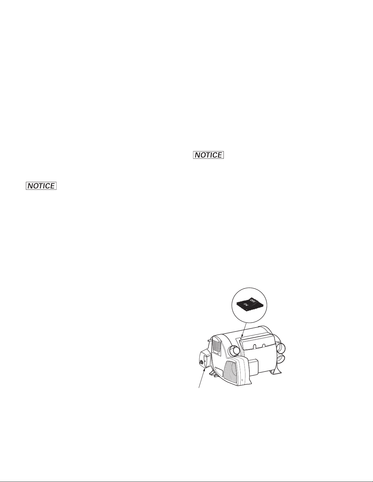
Switch for gas shut-off valve
The switch (Fig. 4) shuts off the power to the
safety gas shut-off valve and with this the gas
supply to the Combi furnace. To make sure that
the gas supply to the furnace is off, turn the
switch to the OFF position.
1. Heating mode
The furnace automatically selects the proper
operating level based on the difference between
the desired temperature set at the control panel
and the current room temperature. If there is
any water in the water container, it will be heated automatically. The water temperature will
not be regulated, but it will reach a maximum of
162°F (72°C).
2. Hot water mode
(only if water container contains water)
Hot water mode is ideal if only hot water is required. The lowest burner setting suffices for
heating water. In hot water mode, the burner will
switch off as soon as the water reaches the temperature selected in the CPplus control panel.
Both modes of operation can be combined.
Switch
for gas shut-o valve
Gas shut-o valve
Fig. 4
Switch positions of the switch for gas shut-off
valve:
Off = gas shut-off valve is closed
On = gas shut-off valve is open
9
Page 10
Room temperature sensor
A room temperature sensor (Fig. 1 – C) measures the temperature inside the RV.
The installation location for the room temperature sensor depends on the RV and will be chosen by the RV manufacturer.
1
2
3
Fig. 5
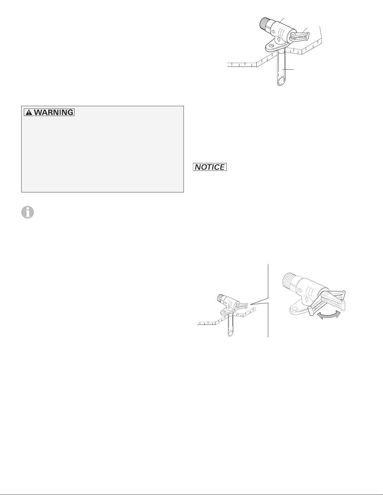
Truma pressure relief/drain valve
Risk of scalding injury from hot water
and/or tampering with the pressure relief/
drain valve!
• Never actuate the pressure relief/drain valve
as long as the Combi furnace is still hot.
• Do not place a plug or reducing coupling
on the outlet part of the valve. If you use a
discharge line, allow the valve and the line
to drain completely.
– The Truma pressure relief/drain valve pro-
vides both the pressure relief function and
a drain function.
– The pressure relief/drain valve is a safety
component and must not be removed for
any reason other than replacement.
– The pressure relief/drain valve is not ser-
viceable; if defective, it must be replaced.
It must be replaced by a certified service
technician.
– It must be replaced by a pressure relief/
drain valve rated for
65.25 psi (4.5 bar) CSA-certified and
registered.
– Tampering with the pressure relief/drain
valve will void the warranty.
1 Truma pressure relief/drain valve
2 Lever
3 Drainage socket (extends through RV’s
undercarriage to outside)
Opening the Truma pressure relief/
drain valve
Danger of damage to the Combi and
the RV due to an obstructed drainage socket!
The drainage socket (Fig. 5 – 3) must be unobstructed and kept clear of obstructions such as
slush, ice, or leaves to ensure that water can
drain properly. No warranty claims for frost damage will be accepted.
• Move the lever so that it is in the “draining”
position (Fig. 6 – c). Water will drain from the
hot water container via the drainage socket(Fig. 5 – 3).
b
c
a
Fig. 6
The Combi furnace with supplementary indirect
water heating must be installed with a pressure
relief valve (Fig. 5) that complies with the standard for Relief Valves for Hot Water Systems,
ANSI Z21.22.
10
a,b = lever in “valve closed during furnace
operation” position
c = lever in “draining” position
Closing the Truma pressure relief/
drain valve
• Move the lever so that it is in the “closed”
position (Fig. 6 – a or 6 – b)
Page 11
Starting the Combi furnace
Danger of over-temperature and toxic exhaust gases!
• Use with LP gas (propane) only. Butane or
any mixtures containing more than 10% of
butane must not be used.
• Keep the air inlet and exhaust gas outlet
free of obstructions. Do not lean any objects against the wall cowl on the RV or
place any objects within a range of 2 feet
(61 cm) of the wall cowl.
Danger of combustion and damage to
persons and the RV!
• Keep the area around the Combi furnace
free from combustible materials, gasoline,
and other flammable vapors or liquids.
• Switch the gas supply and the Combi furnace off
– if anything seems to be out of the ordinary.
– if you smell gas.
– if you move the RV.
– before entering a gas station.
– before entering a tunnel.
– before entering a ferry boat.
:
• The warm air outlets (Fig. 1 – H), the wall
outlet vents (Fig. 1 – I) and the openings
for the circulated air intake (Fig. 1 – D and
Fig.2– 11) must be free from obstructions
to ensure that the furnace functions properly.
Any obstructions might cause the furnace
to overheat. If this happens, the built-in temperature limiter will interrupt the flow of gas
to the furnace. Once the furnace has cooled,
it will switch on again automatically.
• Access to adequate quantities of LPgas
(fuel inlet pressure 11–13in. wc
(27.4–32.4mbar)) and 12V power must be
available.
The Combi eco plus and Combi comfort plus
models
• Make sure that the supply voltage’s fuse
protection of the campground suffices for
operating the furnace in electric mode. The
furnace needs up to 1,700W (14.2A) in operating mode2. If the supply voltage’s fuse
protection is not sufficient, the furnace can
be operated in operating mode1 with up to
850W (7.1A).
Danger of damage to the power
cord due to overheating! If you use an extension cord on a cable drum to connect the
RV to the campground power system, make
sure the cord is fully extended.
Inspections before each use
Check the Combi furnace for the following
points before each use. In case of damage, contact an authorized Truma service provider and
do not operate the Combi furnace.
• Inspect the furnace (Fig. 1 – A), exhaust
venting system (Fig.1 – F), and wall cowl
(Fig.1 – F) for damage. Verify that connections are tight and fasteners are secure.
• The wall cowl (Fig. 1 – F) for drawing in combustion air and emitting exhaust must be
free from obstructions such as slush, ice or
leaves. The furnace will not function properly
if the combustion-air inlet or exhaust tube is
partially or completely obstructed.
Filling the water container
Damage to the water container!
If you want to connect your system to city water, make sure that a suitable pressure reducer
is installed (Fig.1–K). The water container
must not be filled with a pressure exceeding
40.6psi (2.8bar).
1. Close the pressure relief/drain valve, if open
(refer to “Closing the Truma pressure relief/
drain valve” on page 10).
2. Close open bypass lines, if present.
3. Turn on the fresh water supply or switch on
the water pump.
4. Fill the plumbing system:
– Open all water-release points, e.g. cold and
hot water faucets, showers, toilets.
– Once water flows, the plumbing system is
ventilated and filled. Close all water-release
points.
11
Page 12
Switching on the furnace
For the furnace to work properly, there must
be enough LP gas (propane>11in.wc) and
12VDC power. Optionally, for electric or
mixed mode with the
C
ombi comfort plus
power supply is needed.
1. Switch on the furnace’s 12VDC power supply.
2. If necessary, fill the water container with water (refer to “Filling the water container” on
page 11). If no hot water is needed, the
Combi furnace can be operated without being filled.
3. Make sure the supply of LP gas is turned on
at the tank.
4. Make sure the gas shut-off valve is switched
on (refer to “Switch for gas shut-off valve”
on page9).
Operation without gas supply is
possible for the Combi eco plus and
the Combicomfort plus. The maximum
heating power is then 1,700W.
5. Use the CPplus control panel to switch on
the Combi furnace (refer to the CPplus manual for additional instructions).
Combi eco plus
, an additional 120VAC
and
– There may be a variation between the tem-
perature delivered from the Combi furnace
and the temperature at the faucet due to
water conditions or the length of pipe from
the Combi furnace.
– The presence of a flow restrictor in the hot
water line may limit the water flow.
6. If using hot water:
– Use the CPplus control panel to select the
desired water temperature level.
– To obtain the desired water temperature at
the faucet or in the shower, mix cold and
hot water.
– Make sure that the water temperature has
stabilized before any person or animal enters the shower.
Scalding injuries caused by hot air!
Ventilation air can reach 250ºF (121ºC) at the
warm air outlet and it can cause severe burns
or scalding and in extreme cases even death.
• Always check the air temperature before
varying the air throttle position (Fig.1 – H).
7. If using hot air:
– Use the CPplus control panel to set the de-
sired room temperature.
Scalding injuries caused by hot water!
Water temperatures over 127ºF (52ºC) can
cause severe burns or scalding and in extreme
cases even death.
• Before using a hot water faucet or using
the shower, mix with cold water and allow
the hot water to run until the water temperature no longer increases.
• Test the temperature of the water before
placing a child in the bath or shower.
• Do not leave a child or an infirm person in
the bath unsupervised.
Shutdown
Switching off the furnace
1. Switch off the Combi furnace using the
CPplus control panel. Due to internal processes, it may take some time until the furnace is completely shut down.
2. If the Combi furnace and any other gas-powered device is not needed anymore, turn off
the LP gas supply.
3. Switch off the Combi furnace’s electrical
power supply.
If you intend to put the RV into storage
or if you switch off the Combi furnace
during freezing temperatures, refer to
“Winterizing” on page13.
12
Page 13

Draining the water container
Damage to the Combi furnace
caused by freezing!
• The Combi furnace does not have a frost-protection function. The water container must be
drained if the recreational vehicle (RV) will not
be used whenever there is a risk of frost.
No warranty claims for frost damage are
accepted.
Optional: Winterizing the RV with a
winterizing fluid
Winterizing the RV with a winterizing fluid
is only possible with an installed bypass
kit (not in scope of supply), refer to the
RVmanual.
1. Drain the water container (refer to “Draining
the water container” on page13).
To make sure that all water drains properly from the water container, place
a big enough vessel underneath the
drainage socket of the pressure relief/
drain valve (>2.64 gallons (10liters)).
1. Use the main switch or pump switch to
switch off the power to the water-pump
assembly.
2. Turn off or disconnect the city water connection, if present.
3. Open all water release points, e.g. cold and
hot water faucets, showers, toilets.
4. Open the pressure relief/drain valve (refer
to “Opening the Truma pressure relief/drain
valve” on page 10).
The water container will drain via the drainage
socket of the pressure relief/drain valve.
2. Turn the valves of the bypass kit according to the supplier’s or RV manufacturer’s
guidelines.
3. Flush the water system with a suitable winterizing fluid according to the supplier’s or
RV manufacturer’s guidelines.
Before using the Combi furnace again
in hot water mode, remove the winterizing fluid and flush the water system
with potable water.
Winter operation
To operate the Combi furnace in potentially
freezing conditions, the following requirements
must be ensured:
• There must be sufficient LP gas (propane; fuel
inlet pressure 11–13in.wc (27.4–32.4mbar))
in the tank.
Winterizing
Severe damage to the plumbing
components and the Combi furnace!
Damage due to freezing or an unsuitable winterizing fluid is not covered by warranty.
• Follow the recommendations below if the
Combi furnace will be stored under freezing
conditions or for an extended period of time.
• Winterize the Combi furnace at the start of
the winter season or before traveling to a location where freezing conditions are likely.
For winterizing, drain the Combi furnace, refer
to “Draining the water container” on page13.
After draining the water, the Combi furnace is
protected against freezing conditions.
• In addition, the Combi eco plus and
Combicomfort plus models require a supply
voltage of 120V if they are to be operated in
electric or mixed mode.
• For hot water operation, the water container
must be filled (refer to “Filling the water
container” on page11). You must leave
the furnace powered ON whenever freezing
might occur.
Winter operation will not protect the RV’s entire
plumbing system. The RV must be designed for
freezing conditions.
13
Page 14
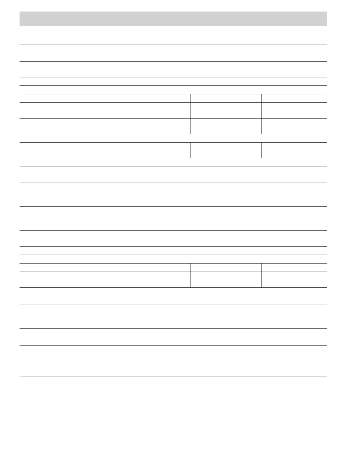
Combi Technical Data
Fuel LP gas (propane only)
Inlet pressure 11–13in. wc (27.4–32.4mbar)
Manifold pressure 10 in. wc (24.9mbar)
Duct static pressure minimum of 0.00in. wc (0.0mbar)
maximum of 0.65in. wc (1.6mbar)
Temperature rise <150°F (83°C)
Energy Input Rate / Gas Consumption
LP gas mode Operating level 1 Operating level 2 Operating level 3
Combi eco
Combi eco plus
Combi comfort
Combi comfort plus
Electric mode
Combi eco plus
Combi comfort plus
Mixed mode LP gas + electric
Combi eco plus
(maximum)
Combi comfort plus
(maximum)
Power supply
Power consumption at 12 VDC (DC < 1Vpp)
Combi eco
Combi eco plus
Combi comfort
Combi comfort plus
Water heating only max. 0.9A
Power consumption at 120 VAC / 60Hz (mains connection or sine wave generator)
Combi eco plus
Combi comfort plus
Hot Water System
Capacity of water container 2.64 gallons (10 liters)
Water heating time from
59°F (15°C) to 140°F (60°C)
Water inlet pressure max. 40.6psi (2.8bar)
System operating pressure max. 65.3psi (4.5bar)
Shipping weight (without water and without peripheral equipment)
Combi eco
Combi comfort
Combi eco plus
Combi comfort plus
7,500BTU/h (2.2kW)
5.3oz/h (150g/h)
7,500BTU/h (2.2kW)
5.3oz./h (150g/h)
850W 1,700W –
7,500 BTU/h (2.2kW) + 1,700 W
14,300 BTU/h (4.2kW) + 1,700 W
transient: max. 6.1 A
(average power consumption: approx. 1.6 A)
transient: max. 6.1 A
(average power consumption: approx. 1.8 A)
Operating level 1 Operating level 2 Operating level 3
7.1A 14.2A –
approx. 23 minutes in hot water mode (measured according to
EN15033)
35.1 lbs.(15.9 kg)
37.0 lbs.(16.8 kg)
14,300BTU/h (4.2kW)
10oz/h (290g/h)
14,300BTU/h (4.2kW)
10oz/h (290g/h)
–
20,400BTU/h (6kW)
14oz/h (410g/h)
14
Page 15

Truma Gerätetechnik GmbH & Co. KG
(“Truma”)
“ Combi” MANUFACTURER’S
LIMITED WARRANTY
This limited warranty pertains solely to the
“ Combi” (the “Product”) manufactured by
Truma and sold through its affiliates and dealers in North America.
Truma warrants subject to the below stated
conditions that the Product will be free from
defects in material and workmanship, and will
perform in accordance with the technical specifications set forth in the description of the Product for a period of twelve (12) months for newly
manufactured parts from the original date of
purchase. The original purchaser is advised
to register the Product within two (2) months
of purchase at www.truma.net in order to
receive an extended warranty of an additional
twelve (12) months. This limited warranty shall
only apply if the Product was properly installed
according to the installation instructions provided and in compliance with applicable codes.
During the warranty period, Truma will repair or
replace, at its own discretion and costs, the defective Product or parts or components of such
Product reported to Truma and which Truma
determines was defective due to a warranty
defect. Costs of diagnosis for a warranty defect
are borne by Truma. Other costs of diagnosis
are not included in this warranty. At the discretion of Truma, the replacement of the Product
or parts or components thereof (i) may be newly
manufactured, (ii) may be assembled from new
or serviceable used parts that are equivalent to
new parts in performance, or (iii) may have been
previously installed.
The customer shall not attempt to repair
the Product or resolve the problem without
the prior consent of Truma. Any attempt
by the customer to repair the Product or
resolve the problem without the prior consent of Truma will void this warranty.
This limited warranty does not cover any defects
attributable in whole or in part to (i) non-Truma
products and services and / or alterations of outof-specification supplies, (ii) accidents, misuse,
negligence or failure of the customer to follow
instructions for the proper use, care and cleaning of the Product, (iii) damages caused in gas
(September 2014)
pressure regulation systems due to foreign substances in the gas (i.e. oil, plasticizers), (iv) external factors (e.g., fire, flood, severe weather),
(v) failure of proper transport packaging, or (vi)
failure by the purchaser to comply with Truma’s
installation and user manual regarding the
Product.
All warranty claims must be reported to Truma’s
authorized warranty service center in the United
States:
Truma Corp Service Center,
825 East Jackson Blvd., Elkhart, IN 46516,
toll free: (855) 558-7862, fax. (574) 538-2426,
[email protected], www.truma.net
The purchaser shall provide the following
information regarding the potential warranty claim
(i) serial number of the defective device, (ii) proof
of purchase, (iii) purchaser’s contact information.
EXCEPT AS EXPRESSLY STATED AND SET
FORTH HEREIN, THERE ARE NO WARRANTIES
OR REPRESENTATIONS, EXPRESS OR IMPLIED,
CONCERNING THE PRODUCT AND NO SUCH
WARRANTIES OR REPRESENTATIONS SHALL
BE IMPLIED UNDER ANY APPLICABLE LAW,
IN EQUITY OR OTHERWISE, INCLUDING
WITHOUT LIMITATION, A WARRANTY OF
MERCHANTABILITY, A WARRANTY OF
FITNESS FOR A PARTICULAR PURPOSE, OR
ANY OTHER WARRANTY WHICH MAY BE
IMPLIED UNDER COMMON LAW OR UNDER
THE UNIFORM COMMERCIAL CODE OF ANY
STATE OR OTHER JURISDICTION OF THE
UNITED STATES OF AMERICA.
Unless further limited herein, the entire liability
of Truma and the customer’s exclusive remedy
for damages from any cause related to or
arising out of a warranty defect, regardless of
the form of action, whether in contract or in
tort, will not exceed the amount of the purchase
price for each purchase order for the Product
which is the subject matter or directly related to
the causes of action asserted.
Unless prohibited under applicable state law, in
no event will Truma, its agents, subcontractors,
affiliates, suppliers and employees be liable for
(a) any incidental, indirect, special or consequential damages, including, but not limited to,
loss of use, revenue, profits or savings, substitute rental or for any other reason, even if Truma
knew or should have known of the possibility of
such losses or damages, (b) claims, demands
or actions against the customer by any person,
except as provided by applicable law.
15
Page 16
Maintenance and service
Repairs must be performed by a qualified service technician. Truma recommends that the
Combi furnace be inspected annually by a qualified service technician.
Danger of electrical shock, fire, scalding
and/or explosion hazard!
Failure to follow safety warnings exactly and
improper servicing could result in dangerous
operation, serious injury, death or property
damage.
• Before servicing, disconnect all electrical
power to the Combi furnace.
Decalcifying and cleaning the water
container
Truma recommends decalcifying and
cleaning the water container at least twice
a year for hygienic reasons. Only use specialized and suitable products. Do not use
chlorine-based products. Read and follow
the instructions of the decalcifying agent’s
manufacturer.
1. For decalcifying the water container, fill the
water container with citric acid and let it
work for some time.
2. Fill citric acid into the fresh water supply and
dilute it with fresh water according to the
supplier’s specification.
• When servicing controls, label all wires
prior to disconnecting. Reconnect wires
correctly.
• Turn off the LP gas supply at the tank.
• Allow the Combi furnace to cool.
• Never actuate the pressure relief valve as
long as the Combi furnace is under water
pressure and/or still warm.
• Verify proper operation after servicing.
Danger of injuries due to sharp edges!
• Always wear protective gloves to avoid
injuries from sharp edges during maintenance work.
There are no serviceable parts inside.
3. Add more than 2.64gallons (10liters) of water to fill up the water container of the Combi
furnace.
4. Drain the mixture of citric acid and water
from the water container (refer to “Draining the water container” on page13) and
flush it with fresh water (refer to “Filling the
water container” on page11).
In order to avoid growth of micro-organisms, regularly heat the water in the boiler
to 158 °F (70 °C) as follows:
– Select energy mode “LP gas” on CPplus
control panel.
– Select the hot water level “boost” on
CPplus control panel.
– When the water temperature is reached
(the display does not flash anymore),
leave the heating switched on for another
30minutes without withdrawing water
from the system. The residual heat in the
device will heat the water to up to 158°F
(70°C).
In case of a defect please contact the Truma
Service Center at 1-855-558-7862 or one of
our authorized service partners to replace the
complete furnace.
For details see www.truma.net.
16
Page 17
Truma pressure relief/drain valve
Risk of scalding injury from hot water
and/or tampering with the pressure relief/
drain valve!
• Never actuate the lever as long as the
Combi furnace is under water pressure
and/or still hot.
• Do not place a plug or reducing coupling
on the outlet part of the valve. If you use a
discharge line, allow the valve and the line
to drain completely.
– The Truma pressure relief/drain valve pro-
vides both the pressure relief function and
a drain function.
– The pressure relief/drain valve is a safety
component and must not be removed for
any reason other than replacement.
– The pressure relief/drain valve is not ser-
viceable; if defective, it must be replaced.
It must be replaced by a certified service
technician.
– It must be replaced by a pressure relief/
drain valve rated for 65.25 psi (4.5 bar)
CSA-certified and registered.
– Tampering with the pressure relief/drain
valve will void the warranty.
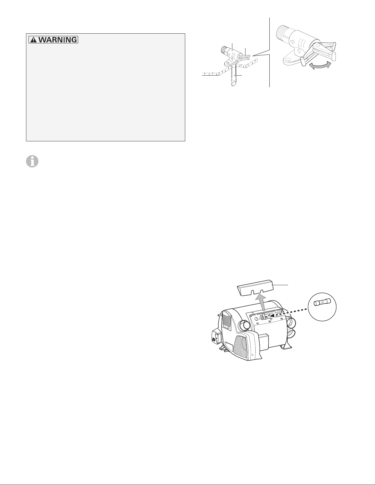
1
2
a
3
b
c
Fig. 7
a,b = lever in “valve closed during furnace op-
eration” position
c = lever in “draining” position
Replacing the 12-volt fuse
Only a qualified service technician may perform
this task.
The fuse is on the printed circuit board underneath the connection cover.
• While detaching or reattaching the connection cover (Fig. 8 – 5), take care to neither
dislodge nor pinch the connector cables.
• A defective fuse must be replaced with the
same make and model of fuse.
10AT time-lag, 5X20 mm. IEC60127-2 Standard
5
• Operate the valve manually at least once per
year to ensure that water channels are clear.
• Before lifting the lever (Fig.7–2), make sure
that the discharge line is securely attached
and properly installed, to prevent injury and
property damage.
• If no water flows when the lever is operated,
check the water supply.
– The water pump must be turned on or the
RV must be connected to city water.
• The pressure relief/drain valve should be inspected every three years by a qualified service technician and be replaced if necessary.
T 10 A
Fig. 8
17
Page 18

Troubleshooting
Faults occurring during operation of the Combi furnace are displayed as an error code on the
CP plus control panel (refer to the Troubleshooting section in the CP plus manual for additional
instructions). The potential cause as well as a solution is described according to the error code
in the CP plus manual.
The potential causes for problems with the water system and the Combi furnace are described
below:
Problem Potential cause Solution
Water heats up too slowly. Lime scale (hard water calcifi-
cation) in the water container.
Water drains. / The hot
water container cannot be
refilled.
The water container cannot
be emptied even though
the pressure relief/drain
valve is open.
Water is dripping / flowing
from the drainage socket
of the pressure relief/drain
valve.
The pressure relief/drain valve
is open.
The drainage socket of the
pressure relief/drain valve is
obstructed.
Water pressure in the water
system is too high.
Decalcify the water container
(refer to “Decalcifying and cleaning
the water container” on page16).
Close the pressure relief/drain valve.
Remove any obstructions such as
slush, ice, or leaves from the opening of the drainage socket.
Make sure that the faucets are
opened in the position “hot”.
Check the pump pressure (a maximum of 40.6 psi (2.8 bar)). Adjust
the pump pressure if necessary. Replace the water pump if an adjustment is not possible.
If you want to connect your system
to city water, make sure that a water
pressure regulator is installed to avoid
filling the water container with a pressure exceeding 40.6 psi (2.8 bar).
Water is slowly dripping
from the drainage socket
of the
valve.
Water escaping at pressure
relief/drain valve.
If none of the measures in the troubleshooting chart proves successful, please contact your dealer,
the Truma Service Center at 1-855-558-7862 or one of our authorized service partners.
18
pressure relief/drain
The pressure inside the water
container rises above a water
pressure of approx. 65,25psi
(4.5 bar) – Truma pressure relief/drain valve installed.
Water pressure in the water
system is too high.
Lime or dirt under the pressure relief/drain valve seat.
The Truma pressure relief/drain
valve protects the water container
against a pressure greater than
65,25psi (4.5 bar). This is not a
fault.
Install a water pressure regulator at
the fresh water supply. This must be
performed only by a qualified service technician.
Rinse the pressure relief/drain valve
to remove contamination from the
valve seat (refer to “Draining the
water container” on page13).
Replace the pressure relief/drain valve.
This must be performed only by a
qualified service technician.
Page 19
Appendix
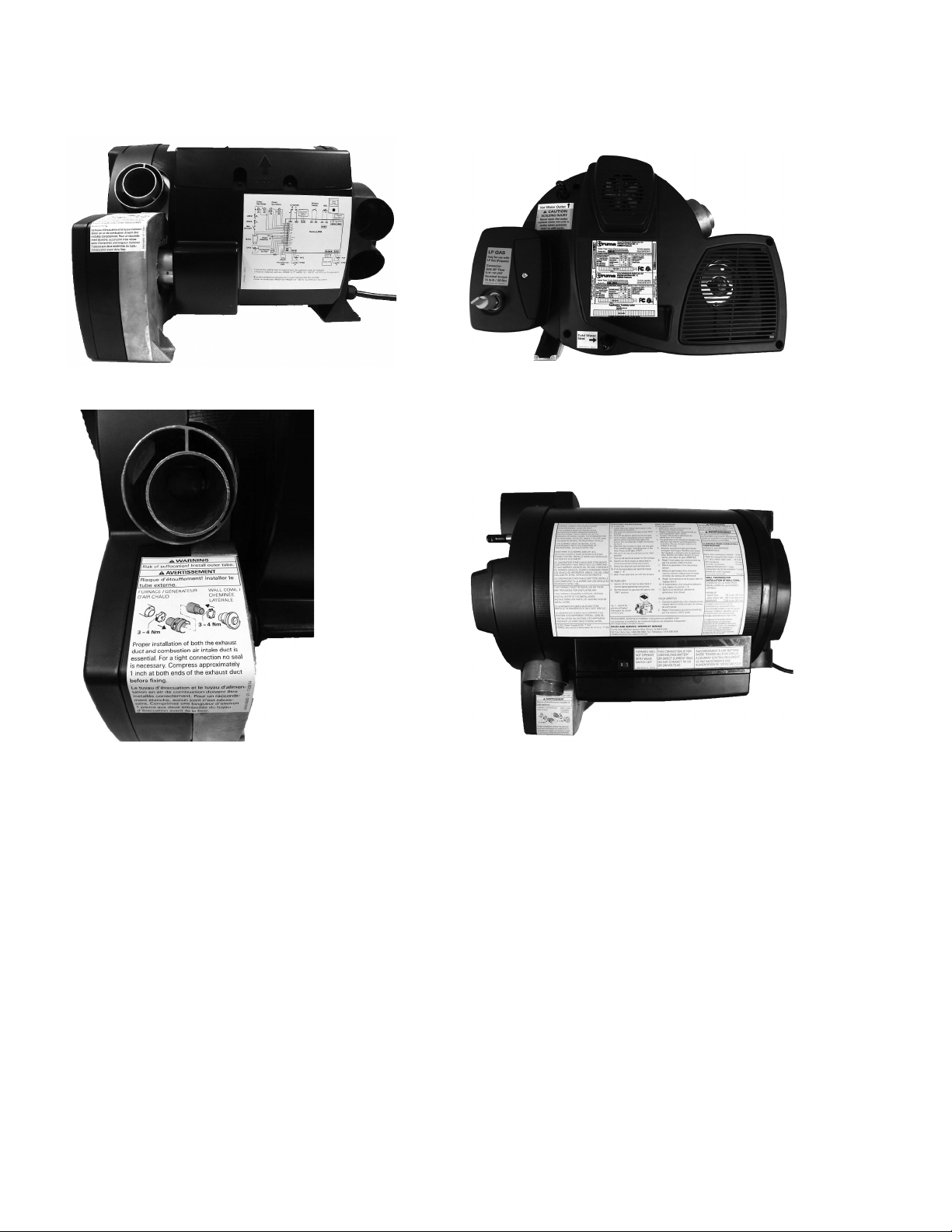
The following pictures show the labels on the Combi furnace. If any of the labels are missing or unreadable, please contact the Truma Service Center on 1-855-558-7862.
Fig. 9 Fig. 10
Fig. 11 Fig. 12
19
Page 20

In case you encounter any problems,
please contact the Truma Service Center
at 855-558-7862 or one of our authorized
service partners. For details see
www.truma.net.
Please have the model number and serial
number (on furnace’s type plate) handy
when you call.
©
34020-00384 · 00 · 03/2017 ·
Truma reserves the right to make technical modifications
Manufacturing
Truma Gerätetechnik GmbH & Co. KG
Wernher-von-Braun-Straße 12
85640 Putzbrunn
Germany
www.truma.com
Sales
Truma Corp
825 East Jackson Blvd.
Elkhart, IN 46516
USA
Toll Free 1-855-558-7862
Fax 1-574-538-2426
[email protected]
www.truma.net
 Loading...