

Page 1
Operating instructions Page 2
Installation instructions Page 11
To be kept in the vehicle!
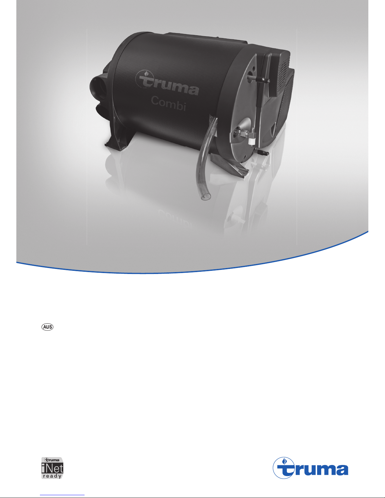
Truma Combi® 2 E / 4 E AU
Page 2
2
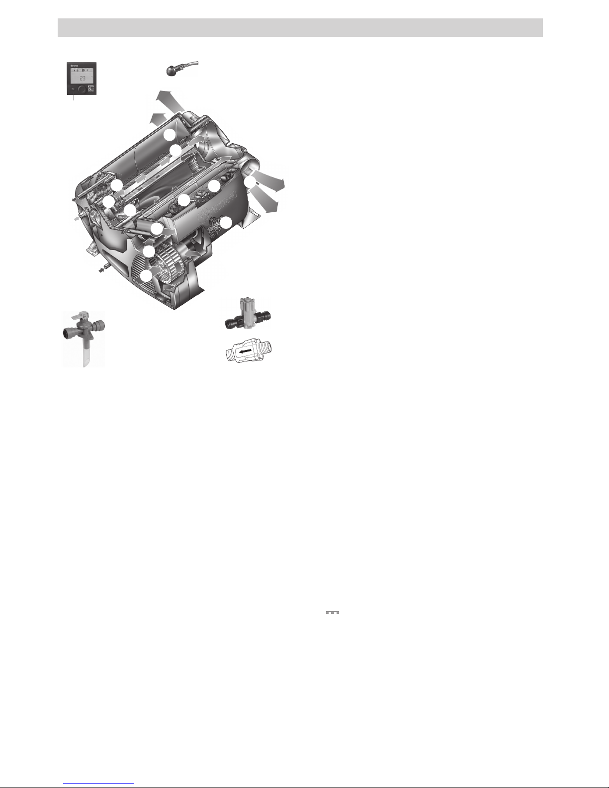
Truma Combi® 2 E / 4 E (Australia)
1 Control panel (digital)
2 Room temperature sensor
3 Cold water connection
4 Hot water connection
5 Gas connection (with pressure test point – not shown)
6 Hot air outlets
7 Recirculated air intake
8 Waste gas discharge
9 Combustion air infeed
10 Electronic control unit
11 Water container (10 litres)
12 Burner
13 Heat exchanger
14 Power electronics
15 Heating elements 240 V
16 Overheating switch 240 V
17 Drain valve
18 Water pressure reducer (A and B)
19 P&T relief valve
1
17
2
3
5
7
8
9
10
10
14
15
16
4
12
13
6
6
18
19
A
B
Fig. 1
Table of contents
Symbols used ........................................................................ 3
Safety instructions ............................................................ 3
Function description ......................................................... 5
Operating instructions
Control panels .................................................................... 6
Room temperature sensor ................................................ 6
Drain valve .......................................................................... 6
P&T relief valve
(Pressure and temperature relief valve) ......................... 6
Filling the hot water system ............................................ 6
Draining the hot water system ........................................ 7
Start-up ................................................................................ 7
Switching off ...................................................................... 7
Maintenance ....................................................................... 7
Fuses .................................................................................... 7
Fuse 12 V ............................................................................... 7
Fuse 240V ............................................................................. 7
Overheating protection 240 V ............................................... 8
Faults .................................................................................... 8
Troubleshooting guide (water supply) ................................... 8
Technical data ..................................................................... 9
Accessories ......................................................................... 9
Truma warranty policy ................................................... 10
Installation instructions
Intended use ........................................................................ 11
Approval .............................................................................. 11
Regulations ......................................................................... 11
Selecting a location ......................................................... 11
Securing the device ......................................................... 12
Exhaust gas removal ....................................................... 12
Installing the wall cowl ........................................................ 12
Connecting the exhaust double duct to the device ............ 13
Recirculated air intake .................................................... 13
Warm air distribution ...................................................... 13
Gas connection ................................................................. 14
Water connection ............................................................ 14
Mounting of the discharge pipe .......................................... 15
Mounting the drain valve .................................................... 15
Installation of the pressure reducer .................................... 15
Water pipe routing .............................................................. 15
Installing the room temperature sensor ...................... 16
Installing the control panel ............................................ 16
Electrical connections ..................................................... 16
12V
voltage supply ...................................................... 17
Room temperature sensor .................................................. 17
Control panel / air conditioning system .............................. 17
Electrical connection 230 ~ / 240 V ~ – option – ........ 17
Function test ..................................................................... 17
Warnings ........................................................................... 17
Trademark information
Truma Combi®, referred to as Combi below.
Page 3

3
Symbols used
The unit must only be installed and repaired by an
expert.
Symbol indicates a possible hazard.
Comment including information and tips.
Observe the ESD regulations! An electrostatic charge
can destroy the electronics. Ensure potential equalisa-
tion before touching the electronics.
Safety instructions
If the gas system is leaking or if there is a
smell of gas:
– extinguish all open flames
– open windows and door
– close all quick-acting valves and gas
cylinders
– do not smoke
– do not activate any electric switches
– ask an expert to inspect the entire system!
Ensuring a safe operating environment
– The unit may be operated only with appropri-
ate Truma control panels and accessories.
– Danger of suffocation! To ensure dissipa-
tion of exhaust gases, operate the appliance
outdoors only. Never use in enclosed spaces
or tents or breathe in the exhaust gases.
– If the cowl has been placed near or directly
beneath an opening window, the appliance
must be equipped with an automatic shut-off
device in order to prevent operation with the
window open.
– Do not place articles on or against this
appliance.
– Do not use or store flammable materials
near this appliance.
– Do not spray aerosols in the vicinity of this
appliance while it is in operation.
– Do not modify this appliance.
– Do not use any after market air filters or
air grills. The use of such components may
cause the unit to overheat.
– Keep flammable materials away from the ar-
ea in front of the hot air outlets. Never block
the hot air outlets.
– In order to avoid overheating of the appliance
keep the air inlets of the device, the air openings to the area in which the appliance is installed and the spacing around the appliance
free of obstruction.
– Keep the cowl for the exhaust duct and com-
bustion air intake free of blockages (slush,
ice, leaves etc.) at all times.
– Warning: Air from the discharge vent may
be hot. Do not place combustible materials
directly in front of the discharge vent. Keep
curtains, bedding and other flammable materials away from the vent.
– Water may drip from the discharge pipe of
the P&T relief valve and this pipe must be
left open to the atmosphere.
– Any discharge pipe connected to the
P&T relief valve is to be installed in a continuously downward direction and in a frost
free ambient.
Obligations of the operator / vehicle owner
– The operator is responsible for the water
filled into the Combi water container and its
quality.
– The vehicle owner is responsible for correct
operation of the appliance.
– The installer or vehicle owner must apply the
yellow sticker with the warning information,
which is enclosed with the appliance, to a
place in the vehicle where it is clearly visible to all users (e.g. on the wardrobe door)!
Ask Dometic Service to send you stickers, if
necessary.
– For your own safety it is absolutely neces-
sary to have the complete gas installation
regularly checked by an expert (at least
every 2 years). The vehicle owner is always
responsible for arranging the gas inspection.
– Check gas hoses regularly and have them
replaced if they become brittle.
Page 4

4
– The use of upright gas cylinders from which
gas is taken in the gas phase is mandatory
for the operation of gas regulators, gas equipment and gas systems. Gas cylinders from
which gas is taken in the liquid phase (e. g.
for forklifts) must not be used, since they
would result in damage to the gas system.
– The operating pressure for the gas supply
is 2.75 kPa and must correspond to the operating pressure of the appliance (see type
plate).
– LPG systems and pressure regulators must
comply with the technical and administrative
regulations of the country in which the appliance is used (AS/NZS 5601).
– We recommend the gas pressure control
system Truma MonoControl CS for vehicles
and the Truma gas pressure control system DuoControl CS for dual-cylinder gas
systems.
– The flow rate of the pressure control device
must correspond to at least the maximum
consumption of all devices installed by the
system manufacturer.
– At temperatures of around 0 °C or less the
gas pressure regulator and the changeover
valve should be operated using the EisEx
regulator heater.
– Controller connecting hoses that meet na-
tional regulations must always be used in the
respective country for which the equipment
is destined.
– Ensure that the inside of the vehicle is suf-
ficiently ventilated. When the unit is started
up, there may be some smoke and/or smell
due to dust or dirt. Especially if it has not
been used for a long time.
– This device may be used by children aged
8 years or above and by persons with
reduced physical, sensory or mental capabilities or lack of experience and / or
knowledge, provided that they are being supervised or have been given instruction with
regard to the safe use of the device and have
understood the potential risks. Children must
not use the device as a toy.
– The integrity and tight fit of the exhaust gas
double duct must be checked regularly, particularly at the end of long trips. Also check
the mounting of the appliance and the cowl.
Safe operation while driving
– Shut OFF gas and the LPG tank when mov-
ing the RV. This disables all gas appliances
and pilot lights. Gas appliances must never
be operated while vehicle is in motion.
– Liquefied gas equipment may not be used
when refuelling, in multi-storey car parks, in
garages, or on ferries.
– If the heater is not being used, always drain
the water if there is a risk of frost. No war-
ranty claims for frost damage will be
accepted.
– To prevent damage to the device from spray
water, such as when cleaning the vehicle, do
not spray water directly into the wall cowl.
Safe handling of malfunctions
– If you notice unusual sounds or smells, close
the gas supply and switch the Combi off.
– Danger of fire / explosion if you attempt to
use a Combi that has been damaged by
flooding or if the vehicle has been involved
in an accident. A damaged Combi must be
repaired by an expert or be replaced.
– The damaged Combi may have to be re-
placed with a new one.
– Only carry out repairs yourself if the solution
is described in the troubleshooting guide of
this manual.
– Following a blow-back (misfire) always have
the exhaust duct checked by an expert.
Safe maintenance and repair
– The unit may only be repaired and cleaned
by authorised persons.
– Children must not carry out maintenance, re-
pair or cleaning work.
Page 5

5
– Guarantee claims, warranty claims and ac-
ceptance of liability will be ruled out in the
event of the following:
– modifications to the unit (including
accessories),
– modifications to the exhaust duct and the
cowl,
– failure to use original Truma parts as re-
placement parts and accessories,
– failure to follow the installation and operat-
ing instructions.
– It also becomes illegal to use the appliance,
and in some countries this even makes it il-
legal to use the vehicle.
– With a new Combi or if the unit has not been
used for some time, rinse all hot/cold water
hoses with drinking water thoroughly before
use.
Function description
The Combi 2 E / 4 E (Australia) liquefied gas heater is a warmair heater with integrated hot water system (10 litre capacity).
The burner is fan-assisted, which ensures that operation is
problem-free, even when on the move. The unit also has heating elements for electrical operation.
In heating and hot water mode the heater can be used to
heat the room and heat water at the same time. If only hot
water is required, select hot water mode.
3 different options are available for operating the unit:
– gas mode only
LPG for autonomous use
– electrical mode only
240 V for stationary use on camp sites
– or gas and electrical mode – mixed mode
Only possible in heating and hot water mode.
Heating and hot water mode
In heating and hot water mode, the unit automatically
selects the required operating level according to the temperature difference between the temperature set on the control
panel and the current room temperature. If the hot water system has been filled, the water is automatically heated as well.
The water temperature depends on the selected operating
mode and the heater output.
All 3 energy selection options can be used for winter
deployment.
– In gas mode the unit automatically selects the operating
level that is required.
– In electrical mode output of 980 W (4.1 A) or 1960 W (8.1 A)
can be manually preselected in accordance with the fuse protection at the camp site.
If more output is required (e.g. heating up or low outside
temperatures) gas or mixed mode should be selected so
that enough heating power is always available.
– In mixed mode 240 V electrical mode is preferred if the
power requirement is low (e.g. for maintaining the room
temperature). The gas burner is not enabled until the power
requirement is higher, and is the first to switch off during
heat-up operation.
Hot water mode
(with filled hot water system only)
Gas mode or 240 V electrical mode is used to generate hot
water. The water temperature can be set to 60 °C.
– In gas mode the water is heated at the lowest burner
setting. Once the water temperature has been reached,
theburner switches off.
– In electrical mode output of 980 W (4.1 A) or 1960 W (8.1 A)
can be manually selected in accordance with the fuse protection at the camp site.
Mixed mode is not possible. With this setting the unit
automatically selects electrical mode. The gas burner is
not enabled.
Page 6

6
P&T relief valve
(Pressure and temperature relief valve)
Risk of scalding injury from hot water and/or tampering with the P&T relief valve!
– Do not actuate the P&T relief valve as long as the
appliance is still hot.
– Do not place a plug or reducing coupling in the dis-
charge pipe (Fig. 3a - 19a) of the P&T relief valve.
– Do not operate the water heater without a
functioning P&T relief valve.
The P&T relief valve (19) is a safety component and must
not be removed for any reason other than replacement.
The P&T relief valve is not serviceable; if defective it must be
replaced (failure to reuse an old P&T relief valve). It must be
replaced by a certified service technician.
Tampering with the P&T relief valve will void the warranty.
19a
Fig. 4
Filling the hot water system
Check whether the drain valve is closed (see “Closing the
drain valve”).
– Switch on the power for the water pump (main switch or
pump switch).
– Open hot water taps in kitchen and bathroom, (set prese-
lecting mixing taps or single-lever fittings to “hot”). Leave
the fittings open for as long as it takes for the hot water
system to displace the air and fill up and the water to flow
without interruption.
If only the cold water system is being operated without
the hot water system, the hot water system also fills up
with water. To avoid frost damage, the hot water system must
be drained via the drain valve, even if it was not operated.
In the event of frost, filling may be prevented by residual water that has frozen. The hot water system can be thawed out
again by briefly starting it up (max. 2 minutes). Frozen lines
can be thawed out by heating up the interior.
If connected to a central water supply (rural or urban
connection), a pressure reducer must be used, which
will prevent pressures of greater than 280 kPa from occurring
in the hot water system.
Read the safety instructions and operating manual carefully before starting the unit.
Operating instructions can be viewed in offline mode
with a mobile device and the Truma App. Download the
operating instructions when you have a WiFi connection and
save them on your mobile device.
Before using for the first time, it is essential to flush
the entire water supply system with clean water. If the
heater is not being used, always drain the water if there is a
risk of frost. No warranty claims for frost damage will be
accepted.
Control panels
The control panels are described in a separate operating
instruction.
Room temperature sensor
To measure the room temperature, an external room temperature sensor (2) is located in the vehicle. The position of the
sensor is determined by the vehicle manufacturer, depending
on the vehicle model. More information can be found in the
operating instructions for your vehicle.
2
Fig. 2
The temperature setting on the control panel depends on personal heating requirements and the design of the vehicle, and
must be determined individually.
Drain valve
The drain valve automatically equalises the pressure in the
event of overpressure in the system. When this occurs, the
water is drained to the outside in intermittent bursts via a
drainage socket.
This drain valve does not protect the water container
from frost damage.
c
b
a
d
Fig. 3
a = Lever in position “Operational – closed”
b = Lever in position “Operational – closed”
c = Lever in position “Drain”
d = Drainage socket (led outside through floor of vehicle)
Opening the drain valve
– Move lever to position (c) – vertical. The water from the hot
water system drains through the drainage socket (d).
The drainage socket (d) of the drain valve must be free of
blockages (slush, ice, leaves, etc.) at all times so the water
can drain easily! No warranty claims for frost damage
will be accepted.
Closing the drain valve
– Move lever to position (a) or (b) – horizontal.
Operating instructions
Page 7
7
Draining the hot water system
If the motor home / caravan is not used during the
winter, the hot water system must be drained! No
warranty claims for frost damage will be accepted.
– Switch off the power to the pump assembly (main switch or
pump switch).
– Open hot water taps in kitchen and bathroom.
In order to check the water that is flowing out, place an
appropriate container (capacity 10 litres) beneath the
drainage socket (d) of the drain valve.
– Open drain valve
(see “Opening the drain valve”).
The hot water system is now drained directly to the outside
via the drain valve. Check whether all of the water in the hot
water system (10litres) has been drained into the container
via the drain valve.
Start-up
The use of the installed control panel is described in
separate operating instructions.
The interior can be heated in gas, electrical or mixed mode,
either with or without water, depending on the setting.
Check whether the power supply fuse protection at the camp
site is adequate for the 980 W (4.1 A) or 1960 W (8.1 A) that
have been selected.
The cable drum must be fully unwound in order to prevent the
power cable from overheating.
– Check to make sure the cowl is unobstructed. Be sure to
remove any covers that may be present.
– Open gas cylinder and quick-acting valve in gas supply line.
– Fill hot water system with water if necessary (see “Filling
the hot water system”).
– Switch on heater at control panel.
Switching off
– Switch off heater at control panel.
The switch-off procedure may be delayed by several
minutes because of internal heater operations.
Always drain water if there is a risk of frost!
If the heater is not going to be used for a long period of time,
close the quick-acting valve in the gas supply line and turn off
the gas cylinder.
Maintenance
Only original Truma parts may be used for maintenance and
repair work!
Servicing should be carried out only by authorised
personnel.
Please contact Dometic Service Centre for service and repairs.
– The drain valve must be actuated regularly (at least twice
per year) in order to remove limescale deposits and to ensure that it is not blocked.
Biofilm, deposits and limescale must be removed using
chemicals to protect the unit from infestation by microorganisms. Only chloride-free products must be used in order to
prevent damage to the unit.
The effectiveness of the use of chemicals to combat microorganisms in the unit can be increased by heating the water
in the hot water system to 70°C at regular intervals.
– Select “Gas” mode.
– Set water temperature to 60 °C.
– Switch on device.
Once the water in the hot water system has reached a
temperature of 60 °C, the burner will switch off. The unit
must stay switched on for at least 30 minutes and no warm
water may be removed. The residual heat in the heat exchanger will heat the water up to 70 °C.
Fuses
Fuse 12 V
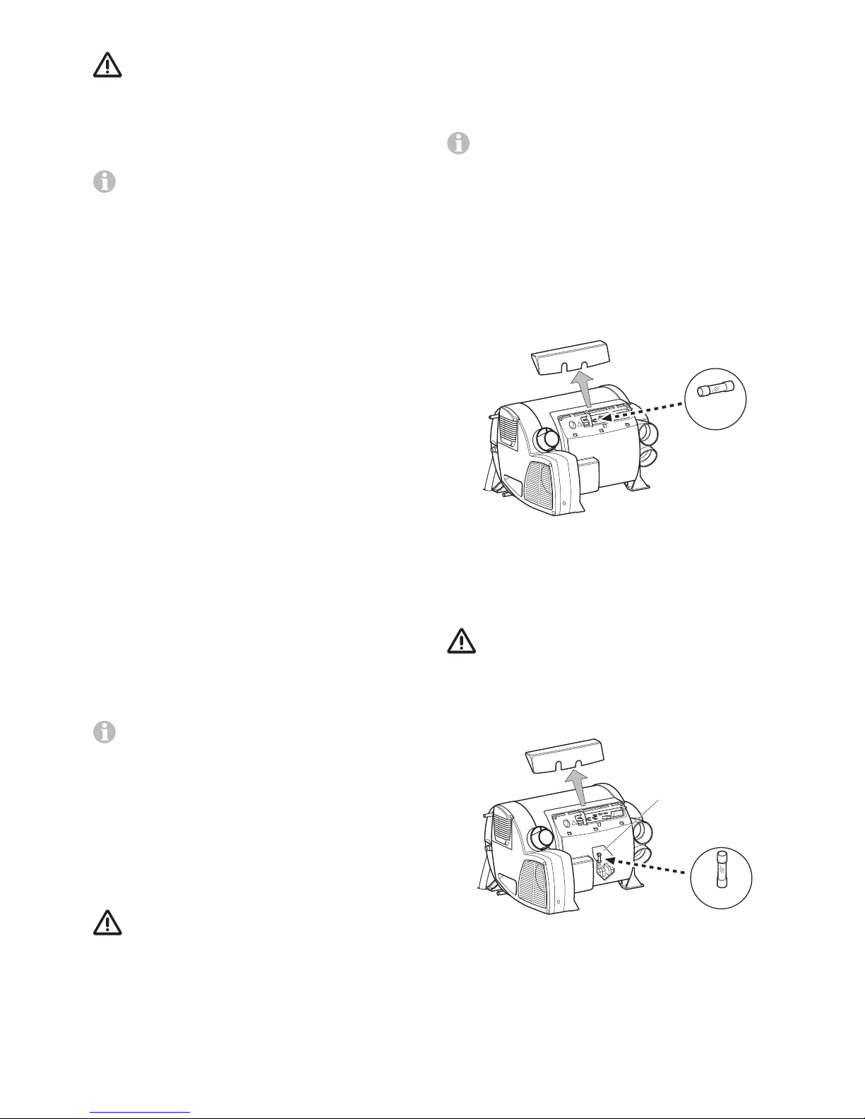
The fuse is in the electronics beneath the connection cover.
Replace the unit’s fuse only with an identical fuse.
Device fuse: 10A – slow – 5 x 20 mm
T 10 A
Fig. 5
Fuse 240V
The fuse and the power supply lines must only be replaced by
an expert!
The unit must be disconnected from the mains (all
poles) before opening the electronic housing lid.
The fuse is in the power electronics (16) beneath the
electronic housing cover.
This fine fuse must always be replaced with a fuse of the
same type: 10 A, slow, interrupting capacity “H”.
T 10 A
14
Fig. 6
Page 8
8
Overheating protection 240 V
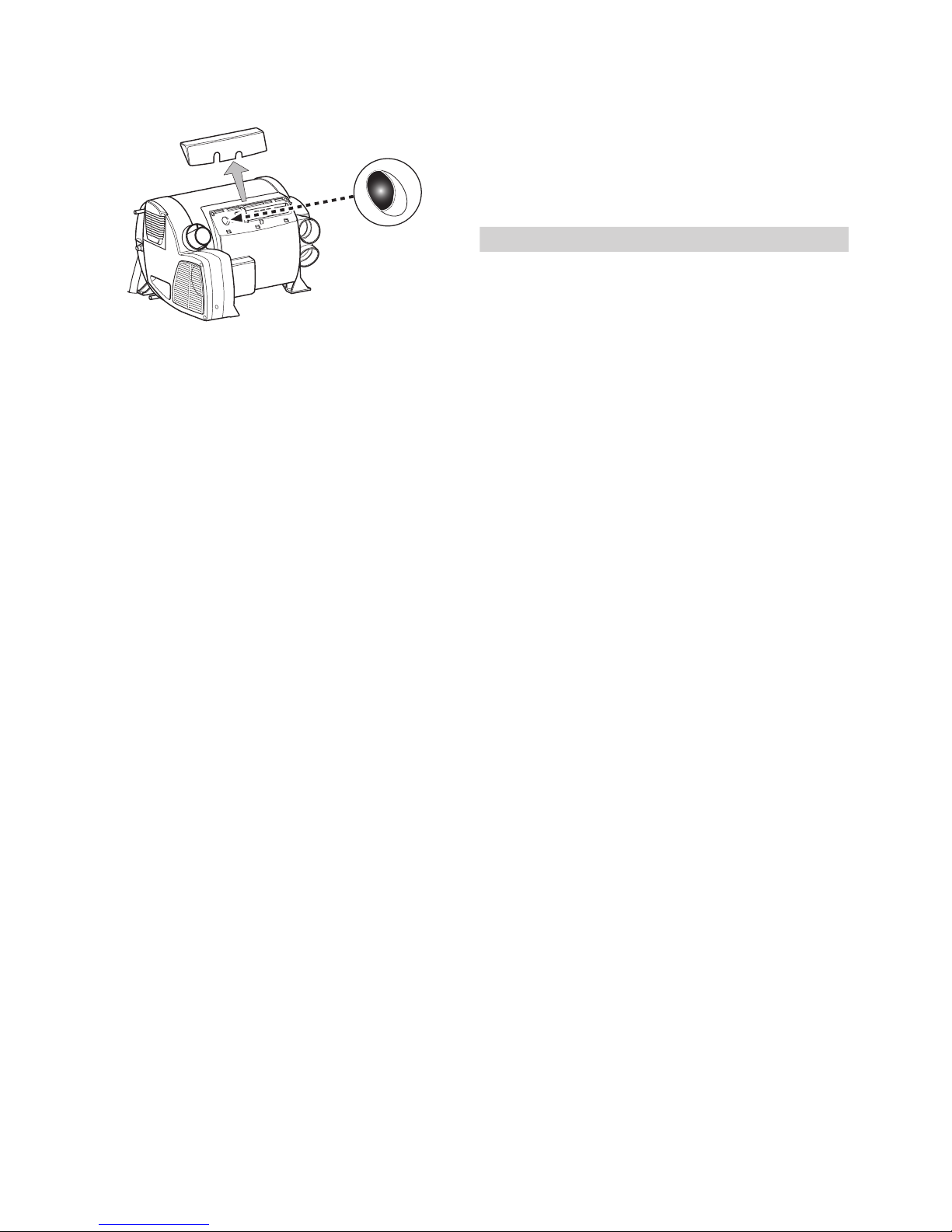
The 240 V heating facility has a mechanical overheating
switch. If the 12 V power supply is interrupted during operation or during the after-run period, for example, the temperatures within the unit could activate the overheating protection.
Fig. 7
To reset the overheating protection, allow heater to cool,
remove connection cover and press red reset button.
Faults
Faults – Heater
Descriptions of possible fault causes and a troubleshooting guide can be found in the operating instructions for the
control panel that is installed.
Faults – Water supply
Possible fault causes and a troubleshooting guide – See
“Troubleshooting guide (water supply)”.
Troubleshooting guide (water supply)
Fault Cause / Remedy
Water taking an extremely
long time to heat up.
Water container furred./
Descale water system
(see“Maintenance”).
Water running out, cannot fill
hot water system.
Drain valve open. / Close drain
valve.
Cannot empty hot water system, even though drain valve
is open.
Drain valve draining connection blocked. / Inspect
opening for blockages (slush,
ice, leaves, etc.) and remove
blockage if necessary.
Water dripping/flowing from
draining socket of drain
valve.
Water pressure too high. /
Check pump pressure (max.
280kPa). If connected to a
central water supply (rural or
urban connection), a pressure
reducer must be used, which
will prevent pressures higher
than 280 kPa entering the hot
water system.
When opening the cold water tap, hot water comes out.
Hot water flows back through
the cold water supply. / Fit a
non-return valve in the cold
water supply (refer to installation instructions “Water
connection”).
If these measures do not rectify the fault, please
contact the nearest Dometic Service Centre.
Disposal
The device must be disposed of in line with the administrative
regulations of the respective country in which it is used. National regulations and laws must be observed.
Page 9
9
Technical data
determined in accordance with EN 624 or Truma test conditions
Protection type / protection class
IP21 / class I
Type of gas
LPG (Liquefied Petroleum Gas – propane / butane)
Operating pressure
2.75kPa (see type plate)
Water capacity
10 litres
Maximum working water pressure
500 kPa
P&T relief valve setting
500 kPa – 99 °C – 10 kW
Heating up time from approx. 15 °C to approx. 60 °C
Hot water system approx. 23 minutes
(measured according to EN 15033)
Heater + hot water system approx. 90 min.
Pump pressure
max. 280 kPa
System pressure
max. 450 kPa
Nominal input (Propane)
Combi 2 E (Australia): 6.9MJ/h
Combi 4 E (Australia): 13.6MJ/h
Thermal output
Electrical operation (240V): 980W/1960 W
Mixed operation (gas and electrical): max. 3900W
Gas operation
Combi 2 E (Australia): max. 1950W
Combi 4 E (Australia): max. 3900W
Gas consumption (Propane)
Combi 2 E (Australia): 130 g/h
Combi 4 E (Australia): 130 – 260 g/h
Air delivery volume (free-blowing without hot-air pipe)
with 3 hot-air outlets max. 249 m³/h
with 4 hot-air outlets max. 287 m³/h
Current input at 12 V
Heater + hot water system
Short-term max. 5.6 A (average power consumption 1.1 A)
Heating up of hot water system: 0.4 A
Stand-by: 0.001 A
Current input at 240 V ~
4.1 A (980 W) or 8.1 A (1960 W)
Weight (not containing water)
Heater unit: 16.2 kg
Heater unit with
peripheral devices: 16.8 kg
Water pressure reducer
Flow range water: 0 – 10 litres/min.
Maximum inlet pressure: 700 kPa
Maximum outlet pressure: 200 kPa
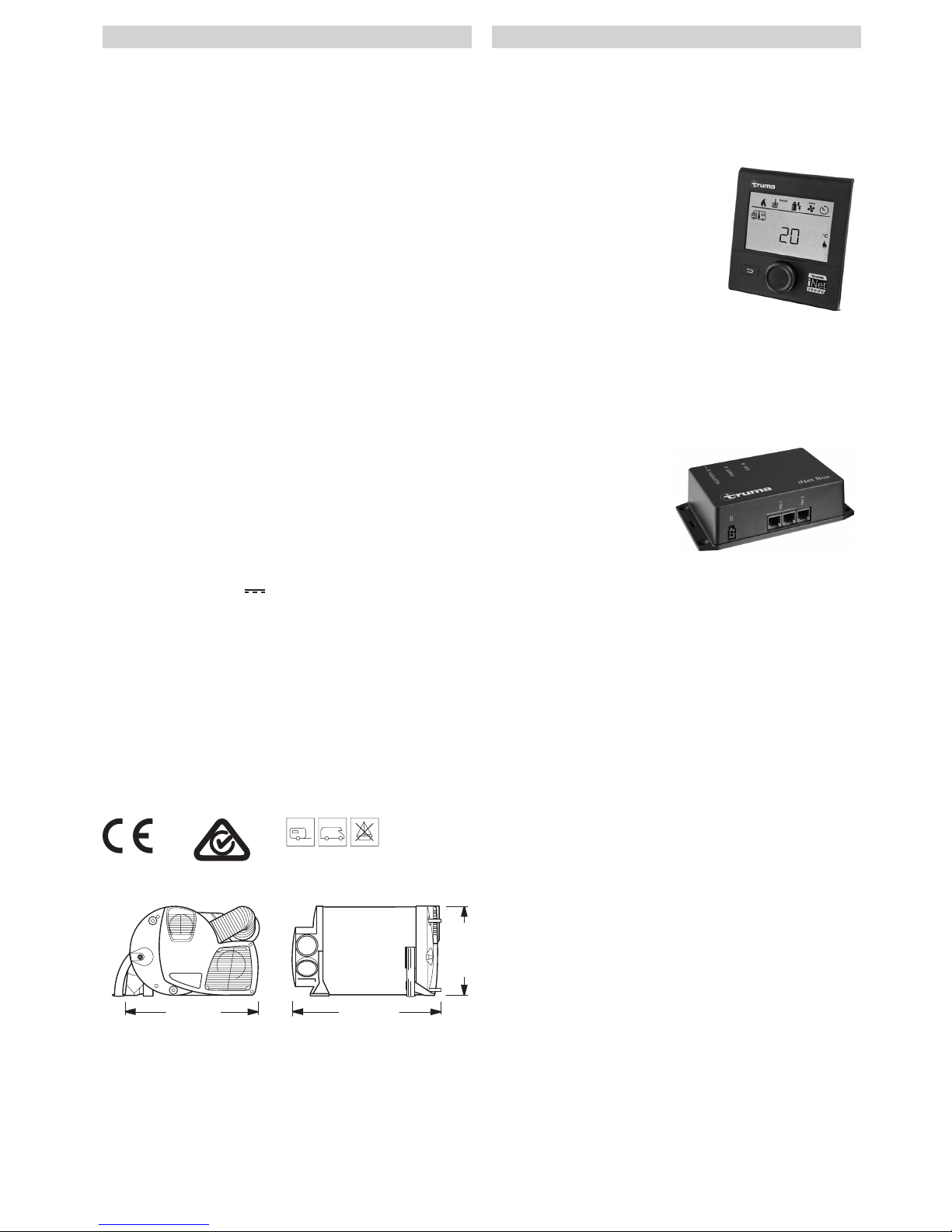
Dimensions
450 mm
510 mm
300 mm
Fig. 8
The right to make technical modifications is reserved!
Accessories
Truma CP plus
Digital control panel Truma CP plus with automatic air conditioning system for the iNet-capable Truma heaters Combi and
Truma air conditioning systems Aventa eco, Aventa comfort
(from serial number 24084022 – 04/2013), Saphir comfort RC
and Saphir compact (from serial number 23091001 – 04/2012)
– The automatic air conditio-
ning system function automatically controls the heater and the air conditioning
system until the required
temperature is reached in
the vehicle.
– With the Truma iNet Box
extension, all TIN-Buscapable Truma devices
can also be controlled
via the Truma App.
Fig. 9
Truma iNet Box
The Truma iNet Box for simple networking and control of
Truma devices with a smartphone or tablet computer using
the app.
– Simple installation and
start-up via the Truma App
– Can be extended with the
update function, which
ensures that it is always up
to date.
Fig. 10
Accessories (without picture) for control panels
– Cable available in different lengths
Page 10

10
Truma warranty policy
The warranty is given by Dometic Pty Ltd, Building 3B,
Clayton Business Park, 1508 Centre Road, Clayton, Victoria,
3168, for 12months from the date of purchase against any
defect arising from faulty materials or workmanship.
Repairs will be carried out during normal business hours only
by Dometic Pty Ltd, or its duly authorised service agents,
and are subject to the warranty conditions and exclusions
hereunder.
Warranty conditions
– The company will only provide service on presentation
of proof of purchase, on either the Truma product, or the
Caravan / RV / Pleasure Craft in which the Truma product
has been installed, to any authorised service agent. The purchaser must allow the service agent to photocopy the proof
of purchase to facilitate his claim to the manufacturer.
– Warranty repairs can only be performed by authorised ser-
vice agents and under no circumstances will Dometic reimburse repairs carried out by unauthorised persons. Tampering with any part of the product by unauthorised personnel
will automatically void the warranty.
– The product must be used solely for domestic purposes. If
the product is used for commercial purposes the warranty
is 6months only.
– Where applicable, the products must be used on the ap-
propriate electrical voltage, gas type and pressure, or fuel
source.
– If at any time during the warranty period any part or parts
are replaced with a part or parts not supplied or approved
by Truma, this warranty shall immediately become void.
Important notice
Before calling a service technician please check carefully
the operating instructions, warranty terms and conditions. If
the product fails for any of the reasons detailed therein, or is
faulty due to abuse, misuse or improper installation, then a
service fee shall be charged to the purchaser.
If you have any queries regarding the interpretation of the
warranty you should contact Dometic Pty Ltd.
Whilst this book represents service outlets at the time of
printing, changes occur from time to time. Should you have
any queries or wish to locate your nearest authorised service
agent please contact Dometic Pty Ltd.
Warranty does not cover
– Any heater which has been:
(a) Subject to misuse, neglect, accident or alteration by any
person.
(b) Damaged or destroyed by fire, flood, act of God or other
inevitable accident.
– Fair wear and tear.
– Damage from foreign substances such as dirt or liquid.
– Travelling expenses or call out fee to and from authorised
service agents’ premises.
– Accommodation or Site Expenses.
– Cleaning of the system or cleaning and adjustment of the
gas system. This is considered to be a part of normal prod-
uct maintenance.
– Non operation of the heater or resultant damage to the
unit where the heater has been operated in an out of level
situation.
– Freight cost of the appliance or parts, to or from, point of
service or transit damage.
– Dometic / Truma are not responsible for resultant loss or
damage sustained by the purchaser.
– Non operation of the appliance or resultant damage to the
unit where the appliance has not been installed, ventilated,
flued or operated in accordance with the manufacturer’s
instructions.
Apart from any warranties implied by the Trade Practices Act
1974 or any relevant State legislation all other warranties express or implied whether arising by virtue of statute or otherwise are hereby excluded.
Page 11
11
Read the installation instructions carefully
prior to starting work and observe the
instructions!
Non-compliance with installation instructions or
incorrect installation can result in endangerment
of persons and property.
This appliance shall be installed in accordance with the manu-
facturer’s installation instructions, local gas fitting regulations,
municipal building codes, electrical wiring regulations. AS/
NZS 5601 “Gas installations”, AS/NZS 3500.4 “Plumbing and
Drainage Part 4: Heated Water Services” and any other statu-
tory regulations.
This appliance delivers hot water at temperatures exceeding
50°C. Refer to AS/NZS 3500 and local regulations regarding
the need for additional hot water delivery temperature control
when hot water is supplied to sanitary fixtures primarily used
for the purpose of personal hygiene.
Please pay attention to the ESD regulations!
Intended use
The Combi 2 E / 4 E (Australia) liquefied gas heater is a warm-
air heater with integrated hot water system (10 litre capacity).
The heater comes with additional electric heating elements,
for operation with a mains voltage of 240V~.
This unit was designed for installation in motor homes and
caravans. The equipment must not be installed in buses (vehi-
cle classes M2 and M3) or vehicles for transporting hazardous
goods. If the equipment is installed in special vehicles, the ap-
plicable regulations must be followed.
Vehicles for hazardous materials
Combustion heaters for gaseous fuel are not permitted.
Approval
Declaration of conformity
The heater Combi 2 E / 4 E (Australia) is approved accord-
ing AS4552, AS4556, AS/NZS 60335.2.21+A1-A3, AS/
NZS 60335.2.30+A1, AS/NZS 60335.1+A1 and fulfils these
standards:
The heater complies with the electromagnetic compatibility
for vehicles regulation UN ECE R10.
SAI Global Certification Number
GAS40016
The year when the equipment was first put into opera-
tion must be indicated with a check on the type plate.
Regulations
Guarantee claims, warranty claims and acceptance of liability
will be ruled out in the event of the following:
– modifications to the unit (including accessories),
– modifications to the exhaust duct and the cowl,
– failure to use original Truma parts as replacement parts and
accessories,
– failure to follow the installation and operating instructions.
It also becomes illegal to use the appliance, and in some
countries this even makes it illegal to use the vehicle.
Installation instructions
In-vehicle installations must comply with the technical and
administrative regulations of the respective country of use
(e.g. AS/NZS5601.2 for vehicles). The national regulations
and rules must be complied with.
More information on the regulations in the relevant destination countries can be requested from our foreign representatives (see www.truma.com).
Selecting a location
The unit and its exhaust duct must always be installed so that
they are easy to access at all times for service work (e.g. gas
and water connection via a service flap, furniture doors etc.)
and are easy to remove and install.
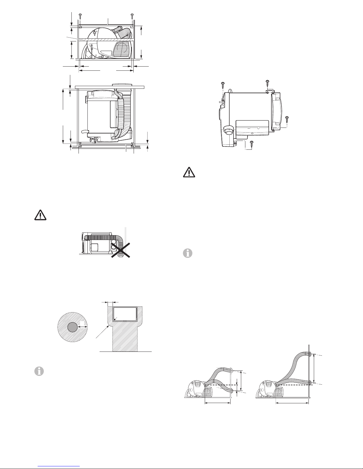
The distance between the unit and surrounding furniture items
or vehicle components must be at least 10 mm on all sides.
The flue and warm air ducts can be installed without clearance. Make sure that there is at least 10mm clearance to
combustible materials around the warm air discharge vent
and 500mm in front of the vent. Locate the vent so that
curtains, bedding, etc. cannot be blown directly in front of or
come into contact with the warm air vent.
For warm air ducting only Truma ducts must be installed.
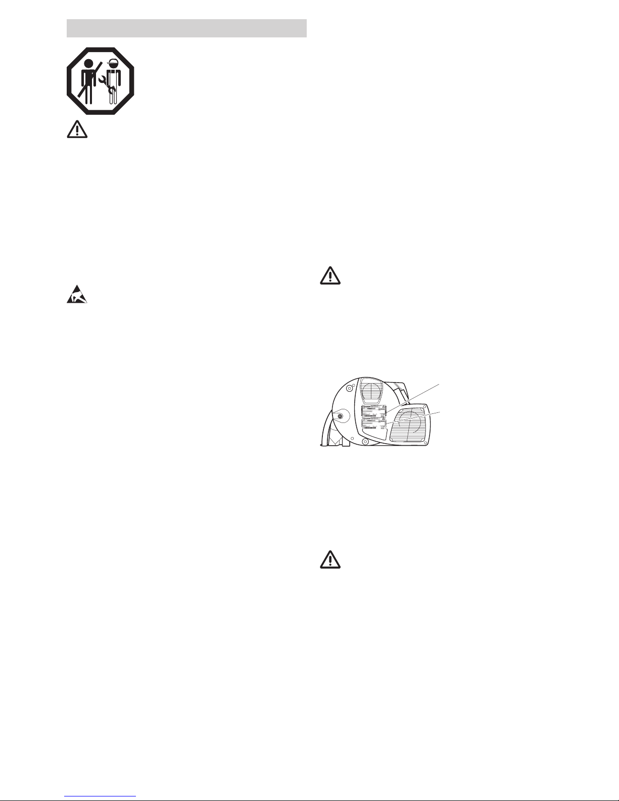
The scope of delivery includes a second type plate (duplicate)
with removable bar code.
If the type plate on the heater is not visible after the heater
has been installed, the second type plate (duplicate) must be
affixed to the unit in a clearly visible location.
The duplicate must only be used in conjunction with the original.
Original
Duplicate
Fig. 11
In order to heat the vehicle evenly throughout, the heater
must be installed in a location in the vehicle that is as central
as possible in a wardrobe, stowage compartment or the like
at a suitable height, so that the air distribution ducts can be
routed with equal lengths. Appropriate openings must be present in the installation compartment so that air can be drawn
in – see relevant sections concerning circulated air intake and
warm air distribution.
In order to reduce the potential danger caused by a
heater becoming loose in the event of an accident, the
upper covering plate (17) of the installation cabinet can be
screwed to other pieces of furniture in a position that makes it
flush with the heater. Depending on the installation situation,
it may be necessary (especially with rear-mounted fixtures) to
install a stable furniture console (18) in front of (next to) the
heater, perpendicular to the direction oftravel. For this purpose, a solid spacer (minimum cross section 30 x 50 mm) can
be attached at a height of approx. 180 mm above the floor, or
a board (18a) for sliding in on a stable furniture console.
There must not be any heat-sensitive materials beneath the
unit (e.g. floor coverings such as PVC, cables etc.), since high
temperatures can occur at the base of the unit.
In order to prevent damage to components inside the equipment, no cables or water lines of any kind may be attached to
the equipment’s insulation.
The operation of important vehicle components must not be
adversely affected.
Page 12
12
Securing the device
Check whether the vehicle has a load-bearing floor or false
floor for securing the heater. If the floor is unsuitable, create a
load-bearing surface beforehand by gluing a plywood board
to the floor, for example.
Screw heater to vehicle floor or false floor using four B 5.5 x 25
screws (included in scope of delivery). Depending on the
situation, it may be possible to secure the heater with three
screws; in this case, always screw aluminium feet (a) and
selectively one of the plastic feet (b) to the vehicle floor.
a
a
b
b
Fig. 15
The heater must be screwed to the floor of the
vehicle or the false floor in order to prevent the
gas system from becoming damaged because of movement while driving!
Exhaust gas removal
Only Truma exhaust duct AA 3 (part no. 39320-00) and
combustion air infeed ZR 80 (part no. 39580-00) may be
used for the Combi 2 E / 4 E (Australia) heater because the
unit was tested and approved only with these ducts.
Do not crush or kink these ducts during installation.
The roof cowl is available as an accessory to the heating
device – assembly instructions are enclosed with the
delivery.
Installing the wall cowl
Permissible duct lengths
The length specifi cations refer to the combusti on air
intake duct.
Ducts with a length of at least 60 cm to a maximum of
100cm can be routed with any amount of rise for the wall
cowl, or with a maximum fall of 20 cm.
Duct lengths from 100 cm to max. 200 cm may only be
installed rising.
max.
20 cm
max. 100 cm
6
0
1
0
-
0
m
c
1
0
0
-
2
0
0
c
m
max. 100 cm
1
0
m
0
c
Fig. 16
350*
180
1
2
500*
12*
540*
10*
10* 10*
5*
10*
Fig. 12
* Minimum dimensions – additional space must be provided for
the gas connection, water connections and the FrostControl
depending on the installation situation. All dimensions in mm.
The cowl must be placed in such a way that exhaust gas
cannot find its way into the vehicle interior.
The cowl must be in the form of a wall or roof cowl
Fig. 13
The wall or roof cowl must be attached so that there is no fuel
tank filler neck or fuel tank breather opening within 500 mm
(R). There must also be no living area ventilation openings or
window openings within 300 mm.
300 mm
300 mm
R
Fig. 14
If the cowl is being installed directly underneath a
window that will be opened, installation of an electric
window switch (part no. 34030-34700) is mandatory.
Information about roof windows
In the case of roof windows (pop-out), the cowl top needs to
protrude at least 10 cm above the opened window. If the cowl
is next to the window, steps must be taken to ensure that,
depending on where it is installed (opened on the right or left),
no exhaust air can enter the open window (e.g. via wind) and
that the cowl has a good supply of incoming air.
Refer to AS/NZS5601.2 – Gas Installations, for location requirements of the flue terminal.
Page 13
13
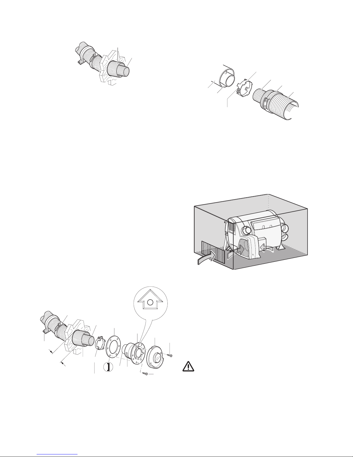
The ducts must be cut to length so that they protrude from
the hole for the cowl after installation. The exhaust duct (1)
must be 10 % longer than the combustion air intake duct (5).
This avoids exhaust duct expansion and tensile load.
1
5
Fig. 17
Installing the wall cowl
Install wall cowl (arrow pointing up) on an even surface
around which wind can flow from all sides. Drill opening with
a diameter of 83 mm (duct hole must be lined with wood in
cavities). Seal with provided rubber seal (8). Use flexible body
sealant on textured surfaces – do not use silicone!
Before pushing the exhaust double duct through the hole,
slide clamp (7) over duct.
Slide rubber seal (8 – smooth side towards cowl, sealing
lips towards wall) onto inner part of cowl (9).
Compress beginning of exhaust duct (1) (approx. 2 cm
thereof) so that the coils are lying against each other.
Slide clip (2 – claws facing cowl) over exhaust duct (1).
Slide exhaust duct (1) onto connection as far as it will go (11 –
bend facing upwards).
Slide on clip (2) as far as it will go (end position must be
between claws of clip) and screw in place.
Slide combustion air intake duct (5) onto toothed connecting
piece (12).
Attach cowl inner part (9) with six screws (13), fit outer part of
cowl (14) and screw on with two screws (15) (screws B3.5x25,
included with delivery).
Use clip (7) to attach combustion air intake duct to connection(12) from inside and (if length greater than 60 cm) attach
to wall with at least one clip ZRS (16 – part no. 39590-00).
16
7
1
5
3 – 4 Nm
2
11
12
9
14
13
8
15
Ø
83 mm
TOP OBEN
Fig. 18
Connecting the exhaust double duct to the device
Compress exhaust duct (1) at its beginning so that the coils
lie next to each other. Slide clip (4 – claws toward unit) over
exhaust duct (1). Slide clip (7) onto combustion air infeed (5).
Slide exhaust duct (1) all the way onto connection (3). Slide
exhaust duct clip (4) as far as it will go (end position must be
between claws of clip) and screw in place. Slide combustion
air intake duct (5) onto connection (6) and secure with clip (7).
6
3
2 – 3 Nm
4
1
5
7
Fig. 19
Recirculated air intake
The circulated air is drawn in by the unit. This must have one
large or several small openings with a total area of at least
150 cm² between the living compartment (not the rear storage space) and the installation compartment.
If a grid (not in scope of supply) is installed (Fig.19), the same
size requirement regarding cross-sectional area (150 cm²) for
drawing in air must be observed.
Fig. 20
The circulated air inlets must be arranged so that exhaust
from the vehicle engine or the heater cannot be drawn in
under normal operating conditions. It must be ensured by
means of construction design that the heating air introduced
into the vehicle is not polluted.
Warm air distribution
Most of the warm air is led into the floor area of the living
compartment via flexible ducts.
The 4 connections on the unit are designed for the 65 mm
diameter ÜR duct (part no. 40230-00).
Only Truma ducts are approved with the heating system
and must be used.
Use only pressure-safe ducts in compliance with Truma quality requirements. Other ducts that do not meet our quality
standard (particularly crown pressure resistance, duct diameter and number of grooves) must not be used.
Page 14
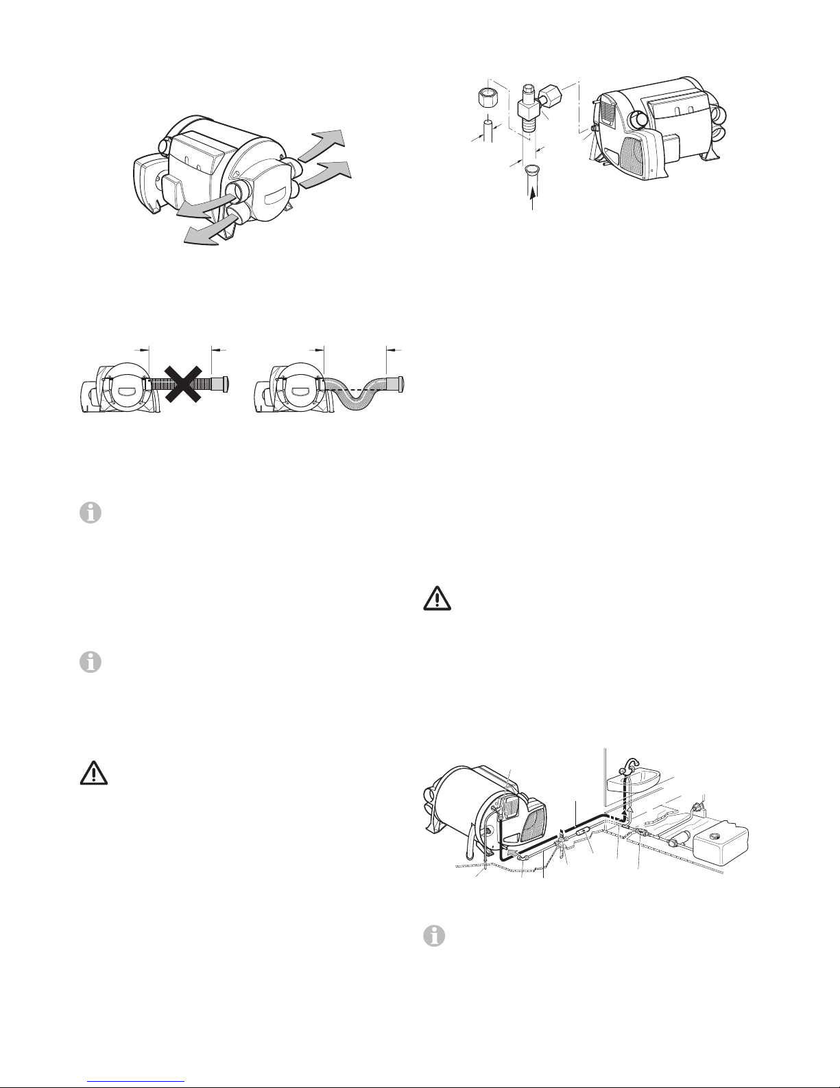
14
If the warm air duct has to be subjected to a considerable
amount of bending immediately behind the warm air outlet
of the unit in confined spaces, we recommend the use of
the BGC 90° elbow (part no. 34091-01). This elbow makes
it possible to connect a ÜR warm air duct with a diameter
of 65 mm or a VR warm air duct with a diameter of 72 mm.
Fig. 21
With a duct length of less than 2 m the air outlet must not
be installed higher than the warm air duct muff. With a duct
length of less than 50 cm, the duct must create a siphon between the connection and the outlet.
L ≤ 50 cmL ≤ 50 cm
Fig. 22
These measures prevent undesirable heating of the vehicle
due to convection (cowl effect) during operation in hot water
mode.
The ducts for warm air distribution must be firmly
inserted into the connections. A clip is attached to each
connection to provide a more secure grip.
For optimum warm air distribution, Truma always recommends
using the 4 warm air outlets of the heater. If only three warm
air outlets are needed, one of the lower warm air outlets must
be sealed with a blank cover VD-Combi (part no. 34310-01).
The blank cover must be firmly pushed into the moulded part
of the heater until it audibly engages and is firmly seated.
Check for firm seating.
If four warm air outlets are being used, a closable end
outlet EN may be installed in one warm air branch. If
there are only 3 warm air outlets, it must be ensured that if a
closable end outlet is being used (e.g. bathroom), a second
non-closable nozzle is installed in the warm air branch.
Gas connection
A gas pressure regulator has to be used, which en-
sures gas supply at gas pressure level 2.75kPa. The
gas supply’s operating pressure must be the same as the
unit’s operating pressure (see type plate). The gas installation must comply with AS/NZS5601.2.
The gas inlet connection on the Combi 2 E / 4 E (Australia) is a
8 mm connection.
Prior to connecting the appliance, make sure that the gas
lines are free from dirt, chips and such!
Gas-connection muff (21) on the unit may not be shortened or
bent.
Route the pipes in a way that will facilitate removing the unit
for service tasks.
To connect, the UNF 1/2" – 20 (SAE Male AN Flare) gas inlet
connection (20) provided with the appliance must be used.
The gas inlet connection is preinstalled. Carefully counterhold
with another spanner when tightening!
For connection to 8 mm steel piping Dometic provides an
adapter UNF 1/2" x RVS 8, part no. 70020-02700.
20
21
UNF 1/2"
8 mm
Fig. 23
Route the pipes in such a way that the appliance can be removed again for servicing.
Refer to AS/NZS5601.2 – Gas Installations, for gas pipe sizing.
It is mandatory that the tightness of the gas installation is
proved before starting up for the first time.
Check for gas leaks (do not check for gas leaks with a naked
flame), then check that the gas pressure is as follows:
LPG: 2.75 kPa
Keep the number of separable connections in the gas supply
line in rooms frequented by people to a technically feasible
minimum.
The gas system must comply with the technical and administrative provisions of the individual country of use (in Australia,
AS/NZS 5601 for motor vehicles).
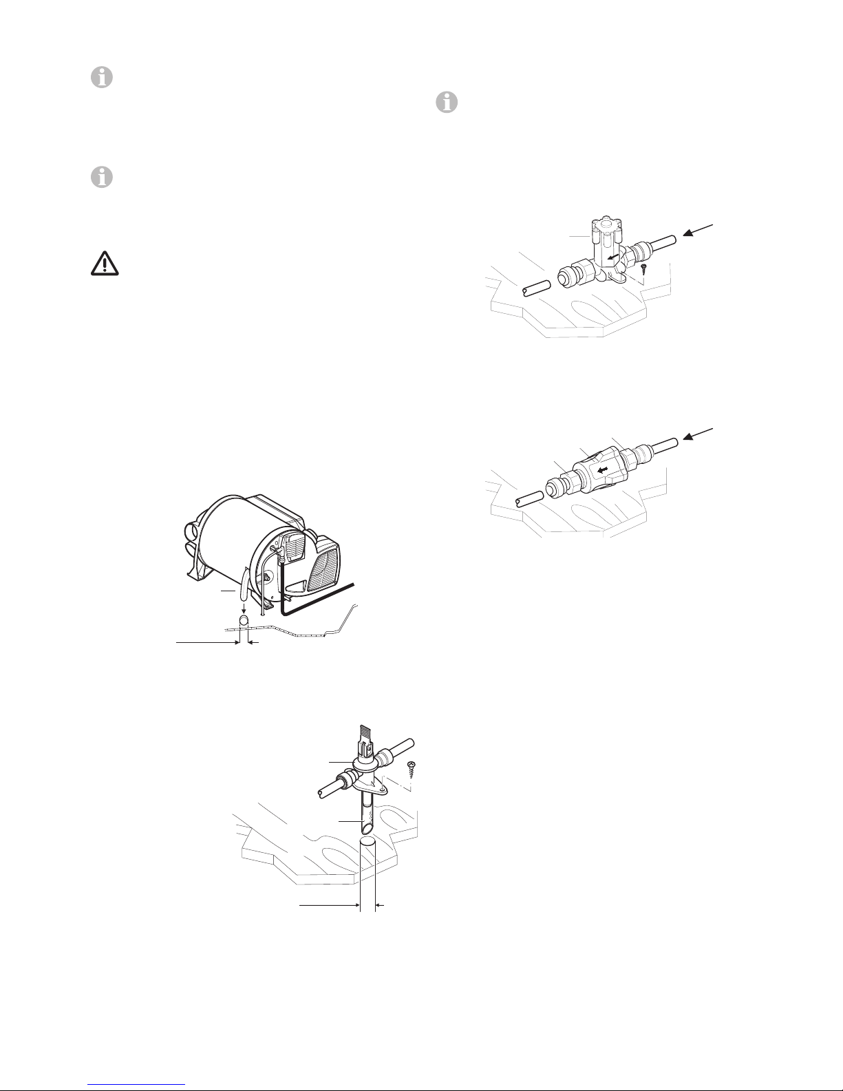
Water connection
For operating the water heater it is possible to use all pressure
pumps and submergible pumps up to 280 kPa, also all mixing
taps with or without electrical switch.
In order to guarantee complete emptying of the
water and to prevent pressures of greater than
450 kPa occurring in the hot water system, the enclosed pressure reducer (18), the enclosed water connectors (27 + 28) and the enclosed drain valve (24) must
be used!
When using pressure pumps with high switching hysteresis,
hot water may flow back through the cold water tap. To prevent the backflow, we recommend that a non-return valve
(nrv – not included in the scope of supply) be fitted between
the outlet to the cold water tap and the drain valve.
18
28
29
2527
26
24
nrv
23
Fig. 24
The supplied water connectors (27+28) and drain valve
(24) have a 12 mm rigid piping connection (e. g. John
Guest System). For connecting to rigid pipes with other diameters appropriate adapters (not included in scope of delivery)
must be used.
Hoses with a diameter of 12mm that are drinking water
compatible, pressure-resistant (up to 450kPa) and hot waterresistant up to +80 °C must be used to connect the unit and
the accessories. We recommend the use of John Guest pipes,
insertion sleeves and hose clamps.
Page 15
15
As accessories Truma supplies the water connectors (27+28)
and drain valve (24) with a 10 mm / 3/8" diameter hose nipple.
The included elbow fittings (27+28) must always be
used in order to completely empty the water and prevent
the water pipes on the unit from leaking over the long-term!
Elbow fitting (28 – with aeration valve) is connected to the
upper warm water connection; the second elbow fitting (27) is
connected to the lower cold water connection.
Route all water lines so they drop down into drain
valve! No warranty claims for frost damage will be
accepted.
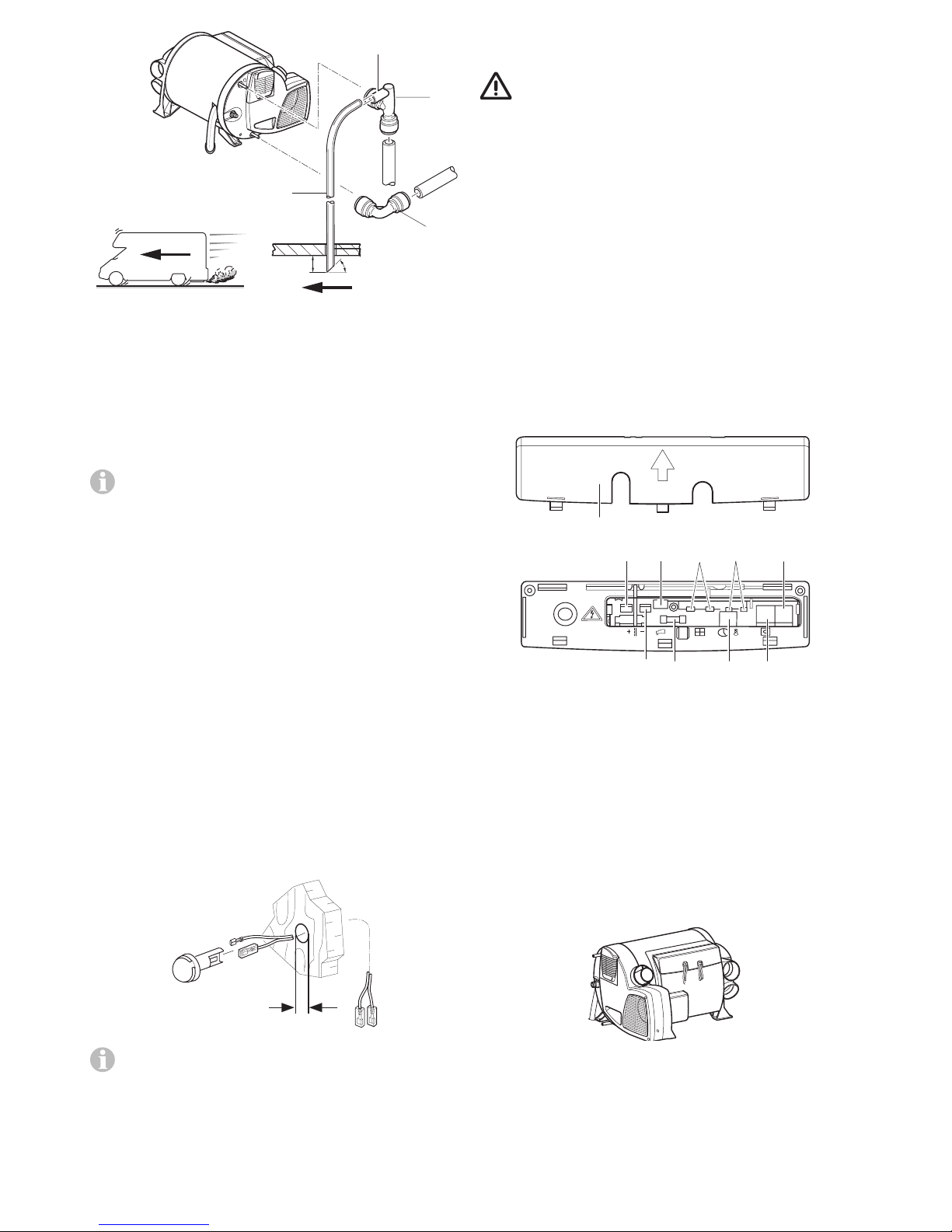
Mounting of the discharge pipe
The discharge pipe (Fig. 25 - 19a) is to be installed
directly to the outside at a position protected against
splash water (apply splash guard, if necessary).
– There must be no tap, valve or other restrictions in
the discharge pipe.
– The discharge pipe must not be connected to other
piping.
– The discharge pipe must fall continously and free
of kinks from the P&T relief valve to the point of
discharge.
– The discharge pipe must not discharge into a safe
tray.
– Drill a hole with 22 mm diameter and pass through the dis-
charge pipe.
Ø 22 mm
19a
Fig. 25
Mounting the drain valve
Mount the drain valve (24)
at an easily accessible
point close to the device.
The draining is to be directly to the outside at a
position protected against
splash water (apply splash
guard, if necessary).
Drill hole with 18 mm diameter and pass through
discharge socket with
hose (24a). Fasten drain
valve with 2 screws.
Ø 18 mm
24
24a
Fig. 26
Installation of the pressure reducer
Depending on the scope of supply – pressure reducer A or B
has to be installed.
For characteristics of the pressure reducer – see „Water
pressure reducer“ page 9.
Pressure reducer A
The pressure reducer (18) must be fitted between the drain
valve and water pump in accordance with the direction of
flow (indicated by arrow).
Fasten the pressure reducer to the floor.
18
2 x
Fig. 27
Pressure reducer B
The pressure reducer (18) must be fitted between the drain
valve and water pump in accordance with the direction of
flow (indicated by arrow).
18
3 Nm
3 Nm
Fig. 28
Water pipe routing
Water pipes (hoses) need to be installed as short as possible without kinks. All hose connections must be secured
with hose clips or John Guest connections with safety rings
(even cold water)! When the water is heated, the resulting
expansion may create pressure levels up to 450kPa until the
P&T relief valve or drain valve triggers (also possible for submersible pumps).
When installing a water supply into the vehicle, ensure that
there is an adequate distance between the water pipes (hoses) and the heat source (e.g. heater, warm air duct).
Hose clips SC (part no. 40712-01) are suitable for fastening
the pipes (hoses) to walls or the floor. These hose clips also
make it possible to route water pipes (hoses) on the heater’s
warm-air distribution pipes as a way to avoid the danger of
frosting.
A water pipe (hose) may only be fitted at a clearance of 1.5m
to the heater on the warm air duct. The Truma hose clip SC
can be used if this distance is observed. In the case of parallel
installations, e.g. openings through a wall, a spacer element
should also be attached (e.g. insulation) to prevent contact.
Connect cold water supply (23) to drain valve (24). To guarantee the correct function of the drain valve, the water pipes/
hoses need to be installed without tension!
Page 16
16
45º20 mm
32
27
28
29
Fig. 29
The elbow fitting (28 – with aeration valve) is inserted into the
upper warm water connection and the second elbow fitting (27)
is inserted in the lower cold water connection of the heater
up to the stop. Pull in opposite direction in order to make sure
the elbow fittings are securely attached.
Create a pipe/hose connection (25) for the cold water supply
between the drain valve (24) and the hot water system intake.
Ensure that the cold water supply does not come into
contact with cold bridges (e.g. the outer wall) in order to
prevent freezing.
Route the hot water supply (26) from the elbow connec tion
with integrated vent valve (28) to the hot water appliances.
Push the venting hose, external diameter 11 mm (29), onto
the hose grommet of the venting valve (28a), and lay it to the
outside without any kinks. Ensure that the bend radius is not
smaller than 40 mm.
Cut off the aeration hose about 20 mm below the vehicle floor
at a 45° angle to the direction of travel (see figure 25).
Check all connections for water leaks:
– Repair leaks as needed.
– Repeat check for water leaks and take any necessary steps
to repair the leaks at all water connections.
Installing the room temperature sensor
When selecting the location, bear in mind that the room temperature sensor must not be subjected to any direct radiant
heat. For optimum room temperature regulation, we recommend that the room temperature sensor be fitted above the
entrance door.
10 mm
Fig. 30
Please ensure that the room temperature sensor is always attached to a vertical wall. There must be no ob-
structions preventing the room air from flowing around it.
Drill a hole 10 mm in diameter. Guide the connection cable
through the drill hole from behind and connect the cable end
to the sensor by means of an insulated connector plug (there
is no need to be concerned about polarity). Slide in the room
temperature sensor and lay the cable end with the two insulated connector plugs to the electronic control unit (extend to
a maximum overall length of 10 m using 2 x 0.5 mm² cable if
necessary).
The provided room temperature sensor must always be
connected, otherwise the heater will switch to fault.
Installing the control panel
The installation of the control panel is described in the instructions included with the control panel.
Electrical connections
Route connecting cables in such a way that they cannot chafe.
Please also use leadthrough bushings or edge protection
profiles where there are sharp edges such as metal panel
leadthroughs. The connecting cables must not be attached to
or come into contact with metal surfaces, the exhaust duct or
warm air ducts.
The electrical connections are located under the connection cover (39). The cover can be removed by pressing and
simultaneously sliding it in the direction of the arrow. When
removing or installing the connection cover on the connection cables, make sure that the cables are not pulled out or
become pinched.
12 V
404142
44
45
46
47
48
43
open
39
Fig. 31
40 = Input voltage +12 V (spade connector 6.3 mm)
41 = Input voltage ground (spade connector 6.3 mm)
42 = not used
43 = Device fuse: 10 A – slow – (T 10 A)
44 = Wire bridge (or window switch – accessory)
45 = not used
46 = Room temperature sensor
47 = Control panel / Diagnostic connector*
48 = Control panel / Diagnostic connector*
* Alternative connections.
All connections to the unit should be made with sagging
connection cables. This will prevent condensation water from
running down the connection cables and into the unit.
Fig. 32
The connecting cables and plugs must not be subjected to
strain. Bundle connecting cables (see figure 29) and secure
each one to housing using a cable binder in order to provide
strain relief.
Page 17
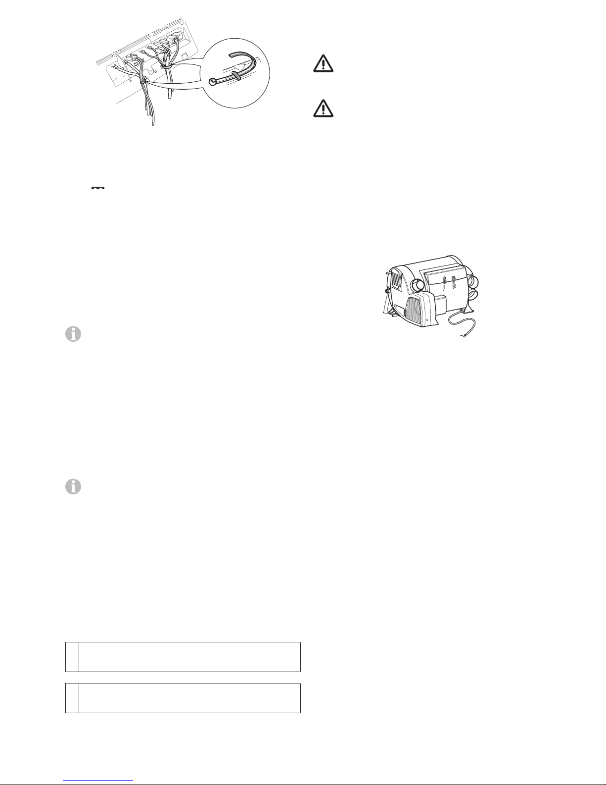
17
Fig. 33
All cables must be securely attached and must not become
loose or disconnected due to vibration – risk of fire!
12V voltage supply
Electric cables, switching units and control units for heaters
must be arranged in the vehicle in such a way that their correct operation cannot be adversely affected under normal operating conditions. All cables leading to the outside must be
splash proof at the leadthrough opening.
Prior to working on electric components the appliance must
be disconnected from the power supply. Switching off at the
control panel is not sufficient!
When carrying out electric welding work on the body, the
appliance connection must be disconnected from the vehicle
electrical system.
The unit is equipped with reverse polarity protection. If
the unit is connected with incorrect polarity, there will be
no display on the LED. The unit can be used after establishing
proper polarity.
To guarantee optimum power supply, the heating system
must be connected to the fused on-board network (central
electronics unit 10 A) with a 2 x 2.5 mm² cable (for lengths
over 6 m with 2 x 4 mm² cable). If relevant, voltage drops in
the supply cable must be taken into account. Connect the
negative lead to the central earth. If connected directly to the
battery, the positive and negative leads must be fused. For the
connections (40, 41), we recommend 6.3 mm fully insulated
flat connectors.
Do not connect any other appliances to the supply line!
When power packs or power supply units are being
used, note that the output voltage is between 11 V and
15 V and the alternating current ripple is < 1.2 Vpp. We recommend the automatic chargers from Truma for the different
applications. Please ask your dealer. Other chargers may be
used only with a 12 V battery as a buffer.
Room temperature sensor
Attach plug of connecting cable to connection (46 – no need
to observe polarity).
Control panel / air conditioning system
The following connecting combinations are possible.
1 CP plus
control panel
Combi 2 E / 4 E (Australia)
(heater with electrical heating
elements)
and
1 Air conditioning
system
Suitable systems – see
CPplus control panel operating
instructions
Insert the plug of the connecting cable into one of the
connections (47 or 48) and engage.
Electrical connection 230 ~ / 240 V ~
– option –
All electrical work and permanent wiring must be car-
ried out by a qualified person in accordance with the
standards AS/NZS 3000, AS/NZS 3001 and all local codes and
regulatory authority requirements.
According to Standard AS/NZS 3001.2008 “Electrical
installations – Transportable structures and vehicles” all
electric circuits must be protected with an RCD (residual current device).
It is imperative for the connection to be made with care using
the correct colours!
An insulating device for providing all-pole insulation from
the mains with contact clearance of at least 3.5 mm must be
provided by the customer for carrying out maintenance and
repair work.
Make connection to power supply by attaching 150 cm long
silicon cable to a line that is protected with as least 10 A (16 A
would be better).
Fig. 34
All cables must be secured with cable clips.
Function test
After installation, the gas feed line must be tested for tightness by the pressure-drop method.
Then test all functions of the unit as described in the operating instructions, especially water drainage. No warranty
claims for frost damage will be accepted.
The operating instructions must be handed over to the vehicle
owner.
Warnings
The installer or vehicle owner must apply the yel low sticker
with the war ning information, which is enclosed with the
appliance, to a place in the vehicle where it is clearly visible
to all users (e.g. on the wardrobe door)! Ask Dometic to send
you stickers, if neces sary.
Page 18

18
Page 19

19
Page 20

34020-00304 · 00 · 09/2016 ·
In Australia, always notify the Dometic Service Centre
if problems are encountered; in other countries the
relevant service partners should be contacted
(www.truma.com).
Having the equipment model and the serial number
ready (see type plate) will speed up processing.
Service (Australia)
Telephone: +61 (0)3 92 39 10 50
Facsimile: +61 (0)3 92 39 10 99
Dometic Pty Ltd
Building 3B,
Clayton Business Park
1508 Centre Road
Clayton, Victoria, 3168
Australia
Dometic New Zealand Ltd.
Post Box 12011
1642 Penrose, Auckland
New Zealand
Service (New Zealand)
Telephone +64 (0)9 622 14 90
Facsimile +64 (0)9 622 15 73
©
 Loading...