

Operating instructions Page 2
Installation instructions Page 11
To be kept in the vehicle!
Truma Combi® 2 E / 4 E AU
2
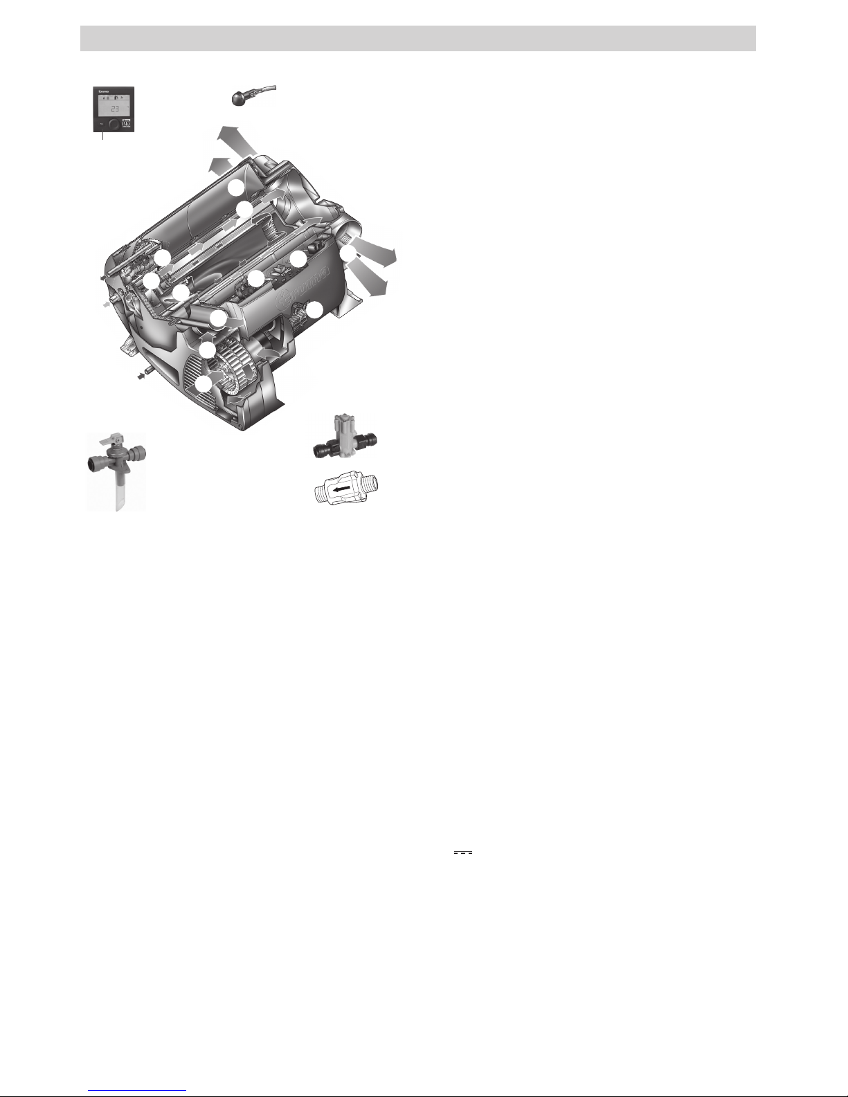
Truma Combi® 2 E / 4 E (Australia)
1 Control panel (digital)
2 Room temperature sensor
3 Cold water connection
4 Hot water connection
5 Gas connection (with pressure test point – not shown)
6 Hot air outlets
7 Recirculated air intake
8 Waste gas discharge
9 Combustion air infeed
10 Electronic control unit
11 Water container (10 litres)
12 Burner
13 Heat exchanger
14 Power electronics
15 Heating elements 240 V
16 Overheating switch 240 V
17 Drain valve
18 Water pressure reducer (A and B)
19 P&T relief valve
1
17
2
3
5
7
8
9
10
10
14
15
16
4
12
13
6
6
18
19
A
B
Fig. 1
Table of contents
Symbols used ........................................................................ 3
Safety instructions ............................................................ 3
Function description ......................................................... 5
Operating instructions
Control panels .................................................................... 6
Room temperature sensor ................................................ 6
Drain valve .......................................................................... 6
P&T relief valve
(Pressure and temperature relief valve) ......................... 6
Filling the hot water system ............................................ 6
Draining the hot water system ........................................ 7
Start-up ................................................................................ 7
Switching off ...................................................................... 7
Maintenance ....................................................................... 7
Fuses .................................................................................... 7
Fuse 12 V ............................................................................... 7
Fuse 240V ............................................................................. 7
Overheating protection 240 V ............................................... 8
Faults .................................................................................... 8
Troubleshooting guide (water supply) ................................... 8
Technical data ..................................................................... 9
Accessories ......................................................................... 9
Truma warranty policy ................................................... 10
Installation instructions
Intended use ........................................................................ 11
Approval .............................................................................. 11
Regulations ......................................................................... 11
Selecting a location ......................................................... 11
Securing the device ......................................................... 12
Exhaust gas removal ....................................................... 12
Installing the wall cowl ........................................................ 12
Connecting the exhaust double duct to the device ............ 13
Recirculated air intake .................................................... 13
Warm air distribution ...................................................... 13
Gas connection ................................................................. 14
Water connection ............................................................ 14
Mounting of the discharge pipe .......................................... 15
Mounting the drain valve .................................................... 15
Installation of the pressure reducer .................................... 15
Water pipe routing .............................................................. 15
Installing the room temperature sensor ...................... 16
Installing the control panel ............................................ 16
Electrical connections ..................................................... 16
12V
voltage supply ...................................................... 17
Room temperature sensor .................................................. 17
Control panel / air conditioning system .............................. 17
Electrical connection 230 ~ / 240 V ~ – option – ........ 17
Function test ..................................................................... 17
Warnings ........................................................................... 17
Trademark information
Truma Combi®, referred to as Combi below.

3
Symbols used
The unit must only be installed and repaired by an
expert.
Symbol indicates a possible hazard.
Comment including information and tips.
Observe the ESD regulations! An electrostatic charge
can destroy the electronics. Ensure potential equalisa-
tion before touching the electronics.
Safety instructions
If the gas system is leaking or if there is a
smell of gas:
– extinguish all open flames
– open windows and door
– close all quick-acting valves and gas
cylinders
– do not smoke
– do not activate any electric switches
– ask an expert to inspect the entire system!
Ensuring a safe operating environment
– The unit may be operated only with appropri-
ate Truma control panels and accessories.
– Danger of suffocation! To ensure dissipa-
tion of exhaust gases, operate the appliance
outdoors only. Never use in enclosed spaces
or tents or breathe in the exhaust gases.
– If the cowl has been placed near or directly
beneath an opening window, the appliance
must be equipped with an automatic shut-off
device in order to prevent operation with the
window open.
– Do not place articles on or against this
appliance.
– Do not use or store flammable materials
near this appliance.
– Do not spray aerosols in the vicinity of this
appliance while it is in operation.
– Do not modify this appliance.
– Do not use any after market air filters or
air grills. The use of such components may
cause the unit to overheat.
– Keep flammable materials away from the ar-
ea in front of the hot air outlets. Never block
the hot air outlets.
– In order to avoid overheating of the appliance
keep the air inlets of the device, the air openings to the area in which the appliance is installed and the spacing around the appliance
free of obstruction.
– Keep the cowl for the exhaust duct and com-
bustion air intake free of blockages (slush,
ice, leaves etc.) at all times.
– Warning: Air from the discharge vent may
be hot. Do not place combustible materials
directly in front of the discharge vent. Keep
curtains, bedding and other flammable materials away from the vent.
– Water may drip from the discharge pipe of
the P&T relief valve and this pipe must be
left open to the atmosphere.
– Any discharge pipe connected to the
P&T relief valve is to be installed in a continuously downward direction and in a frost
free ambient.
Obligations of the operator / vehicle owner
– The operator is responsible for the water
filled into the Combi water container and its
quality.
– The vehicle owner is responsible for correct
operation of the appliance.
– The installer or vehicle owner must apply the
yellow sticker with the warning information,
which is enclosed with the appliance, to a
place in the vehicle where it is clearly visible to all users (e.g. on the wardrobe door)!
Ask Dometic Service to send you stickers, if
necessary.
– For your own safety it is absolutely neces-
sary to have the complete gas installation
regularly checked by an expert (at least
every 2 years). The vehicle owner is always
responsible for arranging the gas inspection.
– Check gas hoses regularly and have them
replaced if they become brittle.

4
– The use of upright gas cylinders from which
gas is taken in the gas phase is mandatory
for the operation of gas regulators, gas equipment and gas systems. Gas cylinders from
which gas is taken in the liquid phase (e. g.
for forklifts) must not be used, since they
would result in damage to the gas system.
– The operating pressure for the gas supply
is 2.75 kPa and must correspond to the operating pressure of the appliance (see type
plate).
– LPG systems and pressure regulators must
comply with the technical and administrative
regulations of the country in which the appliance is used (AS/NZS 5601).
– We recommend the gas pressure control
system Truma MonoControl CS for vehicles
and the Truma gas pressure control system DuoControl CS for dual-cylinder gas
systems.
– The flow rate of the pressure control device
must correspond to at least the maximum
consumption of all devices installed by the
system manufacturer.
– At temperatures of around 0 °C or less the
gas pressure regulator and the changeover
valve should be operated using the EisEx
regulator heater.
– Controller connecting hoses that meet na-
tional regulations must always be used in the
respective country for which the equipment
is destined.
– Ensure that the inside of the vehicle is suf-
ficiently ventilated. When the unit is started
up, there may be some smoke and/or smell
due to dust or dirt. Especially if it has not
been used for a long time.
– This device may be used by children aged
8 years or above and by persons with
reduced physical, sensory or mental capabilities or lack of experience and / or
knowledge, provided that they are being supervised or have been given instruction with
regard to the safe use of the device and have
understood the potential risks. Children must
not use the device as a toy.
– The integrity and tight fit of the exhaust gas
double duct must be checked regularly, particularly at the end of long trips. Also check
the mounting of the appliance and the cowl.
Safe operation while driving
– Shut OFF gas and the LPG tank when mov-
ing the RV. This disables all gas appliances
and pilot lights. Gas appliances must never
be operated while vehicle is in motion.
– Liquefied gas equipment may not be used
when refuelling, in multi-storey car parks, in
garages, or on ferries.
– If the heater is not being used, always drain
the water if there is a risk of frost. No war-
ranty claims for frost damage will be
accepted.
– To prevent damage to the device from spray
water, such as when cleaning the vehicle, do
not spray water directly into the wall cowl.
Safe handling of malfunctions
– If you notice unusual sounds or smells, close
the gas supply and switch the Combi off.
– Danger of fire / explosion if you attempt to
use a Combi that has been damaged by
flooding or if the vehicle has been involved
in an accident. A damaged Combi must be
repaired by an expert or be replaced.
– The damaged Combi may have to be re-
placed with a new one.
– Only carry out repairs yourself if the solution
is described in the troubleshooting guide of
this manual.
– Following a blow-back (misfire) always have
the exhaust duct checked by an expert.
Safe maintenance and repair
– The unit may only be repaired and cleaned
by authorised persons.
– Children must not carry out maintenance, re-
pair or cleaning work.

5
– Guarantee claims, warranty claims and ac-
ceptance of liability will be ruled out in the
event of the following:
– modifications to the unit (including
accessories),
– modifications to the exhaust duct and the
cowl,
– failure to use original Truma parts as re-
placement parts and accessories,
– failure to follow the installation and operat-
ing instructions.
– It also becomes illegal to use the appliance,
and in some countries this even makes it il-
legal to use the vehicle.
– With a new Combi or if the unit has not been
used for some time, rinse all hot/cold water
hoses with drinking water thoroughly before
use.
Function description
The Combi 2 E / 4 E (Australia) liquefied gas heater is a warmair heater with integrated hot water system (10 litre capacity).
The burner is fan-assisted, which ensures that operation is
problem-free, even when on the move. The unit also has heating elements for electrical operation.
In heating and hot water mode the heater can be used to
heat the room and heat water at the same time. If only hot
water is required, select hot water mode.
3 different options are available for operating the unit:
– gas mode only
LPG for autonomous use
– electrical mode only
240 V for stationary use on camp sites
– or gas and electrical mode – mixed mode
Only possible in heating and hot water mode.
Heating and hot water mode
In heating and hot water mode, the unit automatically
selects the required operating level according to the temperature difference between the temperature set on the control
panel and the current room temperature. If the hot water system has been filled, the water is automatically heated as well.
The water temperature depends on the selected operating
mode and the heater output.
All 3 energy selection options can be used for winter
deployment.
– In gas mode the unit automatically selects the operating
level that is required.
– In electrical mode output of 980 W (4.1 A) or 1960 W (8.1 A)
can be manually preselected in accordance with the fuse protection at the camp site.
If more output is required (e.g. heating up or low outside
temperatures) gas or mixed mode should be selected so
that enough heating power is always available.
– In mixed mode 240 V electrical mode is preferred if the
power requirement is low (e.g. for maintaining the room
temperature). The gas burner is not enabled until the power
requirement is higher, and is the first to switch off during
heat-up operation.
Hot water mode
(with filled hot water system only)
Gas mode or 240 V electrical mode is used to generate hot
water. The water temperature can be set to 60 °C.
– In gas mode the water is heated at the lowest burner
setting. Once the water temperature has been reached,
theburner switches off.
– In electrical mode output of 980 W (4.1 A) or 1960 W (8.1 A)
can be manually selected in accordance with the fuse protection at the camp site.
Mixed mode is not possible. With this setting the unit
automatically selects electrical mode. The gas burner is
not enabled.

6
P&T relief valve
(Pressure and temperature relief valve)
Risk of scalding injury from hot water and/or tampering with the P&T relief valve!
– Do not actuate the P&T relief valve as long as the
appliance is still hot.
– Do not place a plug or reducing coupling in the dis-
charge pipe (Fig. 3a - 19a) of the P&T relief valve.
– Do not operate the water heater without a
functioning P&T relief valve.
The P&T relief valve (19) is a safety component and must
not be removed for any reason other than replacement.
The P&T relief valve is not serviceable; if defective it must be
replaced (failure to reuse an old P&T relief valve). It must be
replaced by a certified service technician.
Tampering with the P&T relief valve will void the warranty.
19a
Fig. 4
Filling the hot water system
Check whether the drain valve is closed (see “Closing the
drain valve”).
– Switch on the power for the water pump (main switch or
pump switch).
– Open hot water taps in kitchen and bathroom, (set prese-
lecting mixing taps or single-lever fittings to “hot”). Leave
the fittings open for as long as it takes for the hot water
system to displace the air and fill up and the water to flow
without interruption.
If only the cold water system is being operated without
the hot water system, the hot water system also fills up
with water. To avoid frost damage, the hot water system must
be drained via the drain valve, even if it was not operated.
In the event of frost, filling may be prevented by residual water that has frozen. The hot water system can be thawed out
again by briefly starting it up (max. 2 minutes). Frozen lines
can be thawed out by heating up the interior.
If connected to a central water supply (rural or urban
connection), a pressure reducer must be used, which
will prevent pressures of greater than 280 kPa from occurring
in the hot water system.
Read the safety instructions and operating manual carefully before starting the unit.
Operating instructions can be viewed in offline mode
with a mobile device and the Truma App. Download the
operating instructions when you have a WiFi connection and
save them on your mobile device.
Before using for the first time, it is essential to flush
the entire water supply system with clean water. If the
heater is not being used, always drain the water if there is a
risk of frost. No warranty claims for frost damage will be
accepted.
Control panels
The control panels are described in a separate operating
instruction.
Room temperature sensor
To measure the room temperature, an external room temperature sensor (2) is located in the vehicle. The position of the
sensor is determined by the vehicle manufacturer, depending
on the vehicle model. More information can be found in the
operating instructions for your vehicle.
2
Fig. 2
The temperature setting on the control panel depends on personal heating requirements and the design of the vehicle, and
must be determined individually.
Drain valve
The drain valve automatically equalises the pressure in the
event of overpressure in the system. When this occurs, the
water is drained to the outside in intermittent bursts via a
drainage socket.
This drain valve does not protect the water container
from frost damage.
c
b
a
d
Fig. 3
a = Lever in position “Operational – closed”
b = Lever in position “Operational – closed”
c = Lever in position “Drain”
d = Drainage socket (led outside through floor of vehicle)
Opening the drain valve
– Move lever to position (c) – vertical. The water from the hot
water system drains through the drainage socket (d).
The drainage socket (d) of the drain valve must be free of
blockages (slush, ice, leaves, etc.) at all times so the water
can drain easily! No warranty claims for frost damage
will be accepted.
Closing the drain valve
– Move lever to position (a) or (b) – horizontal.
Operating instructions
 Loading...