

Page 1

Operating instructions Page 2
To be kept in the vehicle!
Combi (E)
Page 2
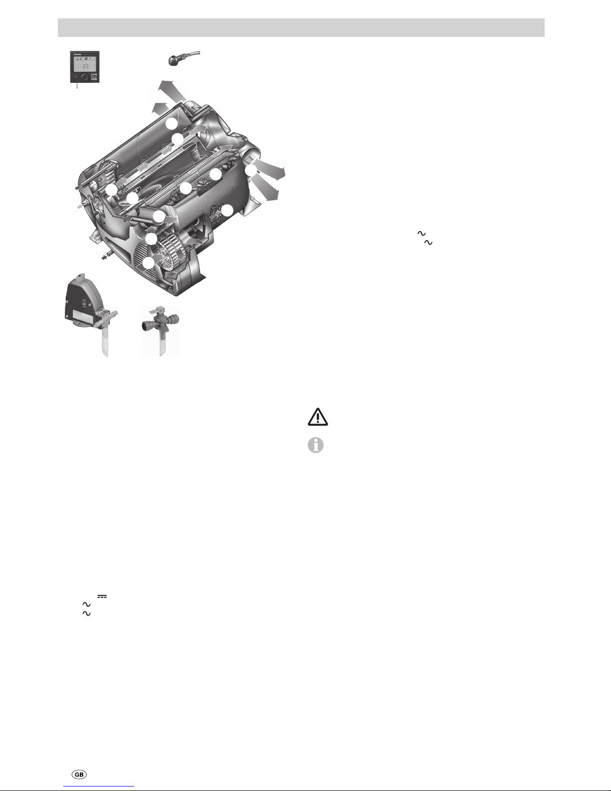
2
1 Control panel, digital or analogue (no picture)
2 Room temperature sensor
3 Cold water connection
4 Hot water connection
5 Gas connection
6 Warm air outlets
7 Circulated air intake
8 Exhaust gas discharge
9 Combustion air infeed
10 Electronic control unit
11 Water container (10 litres)
12 Burner
13 Heat exchanger
14 Power electronics
15 Heating elements 230 V
16 Overheating switch 230 V
17 FrostControl (safety/drain valve – UK version optional)
18 Safety/drain valve (UK version)
Inhaltsverzeichnis
Symbols used ........................................................................ 2
Intended use .......................................................................... 2
Safety instructions ............................................................ 3
Function description (Combi) ............................................ 5
Function description (Combi E) ......................................... 5
Operating instructions
Control panels .................................................................... 6
Room temperature sensor ................................................ 6
Safety/drain valve .............................................................. 6
A. FrostControl ..................................................................... 6
B. Safety/drain valve ............................................................. 6
Filling the boiler ................................................................. 7
Draining the boiler ............................................................. 7
Start-up ................................................................................ 7
Switching off ...................................................................... 7
Maintenance ....................................................................... 7
Fuses .................................................................................... 8
Fuse 12 V
.......................................................................... 8
230 V
fuse (Combi E) ........................................................ 8
230 V
overheating protection (Combi E) .......................... 8
Techn i c a l data ..................................................................... 8
Dimensions ........................................................................... 9
Disposal ............................................................................... 9
Faults .................................................................................... 9
Troubleshooting guide (water supply) ................................... 9
Accessories ....................................................................... 10
Manufacturer’s Warranty
(European Union) .............................................................. 10
Combi (E)
Symbols used
Symbol indicates possible hazards.
Note containing information and tips.
Intended use
The liquid gas heater Combi is a warm-air heater with integrated hot water boiler (10 litre volume). This unit was designed for installation in motor homes (vehicle class M1) and
caravans (vehicle class O).
It must not be installed in buses (vehicle classes M2 and M3)
or in vehicles for transporting hazardous goods.
17 18
2
3
5
7
8
9
11
10
14
15
16
4
12
13
6
6
1
Figure 1
Page 3

3
Safety instructions
What must I do if I smell gas?
– Extinguish all naked flames
– Open windows and doors
– Close all quick-acting valves and gas cylinders
– Do not smoke
– Do not operate any electrical switches
– Have the entire gas system checked by an
expert.
A safe operating environment
– The unit may be operated only with appropri-
ate Truma control panels and accessories.
– Danger of toxic exhaust fumes. The heater’s
exhaust can be toxic in enclosed spaces (e.g.
garages, workshops). If the vehicle is parked
in closed rooms:
– Shut off the fuel supply to the heater
– Deactivate the time switch
– Switch off the heater at the control panel.
– If the cowl has been placed near or directly
beneath an opening window, the appliance
must be equipped with an automatic shut-off
device in order to prevent operation with the
window open.
– Heat-sensitive objects (e.g. spray cans) or
flammable materials/ liquids must not be
stored in the same compartment where the
appliance is installed because, under certain
conditions, this area may be subject to elevated temperatures.
– Keep flammable materials away from the
area in front of the warm air outlets. Never
block the warm air outlets.
– The openings for circulated air intake, the in-
stallation compartment and the space around
the unit must be kept free of obstacles so
that the unit does not overheat.
– Keep the cowl for the exhaust duct and
combustion air intake free of contamination
(slush, ice, leaves etc.) at all times.
– Danger from hot surfaces and exhaust gas.
Do not touch the area around the wall cowl
and do not lean any objects against the wall
cowl or the vehicle.
Obligations of the operator / vehicle owner
– The operator is responsible for the water
with which the Combi boiler is filled and for
its quality.
– The vehicle owner is responsible for correct
operation of the appliance.
– The installer or vehicle owner must affix the
supplied yellow sticker with the warning
information in a location in the vehicle
where it is clearly visible to all users (e.g.
the wardrobe door). Missing stickers can be
requested from Truma.
– Liquid gas systems must comply with the
technical and administrative regulations of
the respective country of use (e.g. EN 1949
for vehicles in Europe). The national legislation and regulations (e.g. DVGW Work
Sheet G 607 for vehicles in Germany) must
be observed.
– The vehicle owner must arrange for the
gas system to be tested (in Germany every
2 years) by a liquid gas expert (DVFG, TÜV,
DEKRA). The test must be confirmed on the
respective test certificate (G 607).
– Pressure regulating devices and hoses must
be replaced with new ones no more than
10 years after their date of manufacture
( every 8 years if used commercially).
– Inspect hose lines regularly and have them
replaced if they are broken.
– If the heater is not being used, always drain
off the water if there is a risk of frost. No
claims may be made under the warranty for
damage caused by frost.
Safe operation
– The use of upright gas cylinders from which
gas is taken in the gas phase is mandatory
for the operation of gas pressure regulation
systems, gas equipment and gas systems.
Gas cylinders from which gas is taken in the
liquid phase (e. g. for fork lifts) must not be
used, since they would result in damage to
the gas system.
– The operating pressure of the gas supply
(30 mbar) and of the appliance (see type
plate) must be the same.
Page 4

4
– In Germany, only pressure regulating equip-
ment that complies with DIN EN 16129 (in
vehicles) with a fixed output pressure of
30 mbar may be used for the gas system.
The flow rate of the pressure regulating
equipment must correspond to at least the
maximum consumption of all devices installed by the system manufacturer.
– We recommend the Truma MonoControl CS
gas pressure regulation system for vehicles
and the Truma DuoComfort / DuoControl CS
gas pressure regulation system for dual-cylinder gas systems.
– At temperatures of around 0 °C and below,
the gas pressure regulation system or the
changeover valve should be operated with
the EisEx regulator heater.
– Suitable hoses that meet national regulations
must always be used in the respective country
for which the equipment is destined.
– Ensure that the inside of the vehicle is suf-
ficiently ventilated. When the unit is started
up, there may be some smoke and/or smell
due to dust or dirt. Especially if it has not
been used for a long time.
– This appliance can be used by children aged
8 and over, as well as by persons with reduced physical, sensory or mental capabilities or with a lack of experience and knowledge, provided that they are supervised or
have been instructed on how to use the appliance safely and that they understand the
resulting risks. Children must not be allowed
to play with the appliance.
– The integrity and tight fit of the exhaust
double duct must be checked regularly,
particularly at the end of long trips. Also
check the mounting of the unit and the cowl.
Operation while driving
– Directive UN ECE R 122 stipulates that a
safety shut-off device is required if motor
homes and caravans are heated while driving. The Truma MonoControl CS gas pressure regulation system satisfies this requirement. Throughout Europe, a type-tested
liquefied gas heating system may be used
while driving (according to the directive
UN ECE R 122) if the system includes a gas
pressure regulator with an appropriately configured gas installation. National regulations
and rules must be followed.
– If no safety shut-off device (e.g. as contained
within the Truma MonoControl CS gas pressure regulation system) has been installed,
the gas cylinder must be closed when driving and information signs must be attached in the gas cylinder protection box and
in the vicinity of the control panel.
– Liquid gas equipment must not be used
when refuelling, in multi-storey car parks, in
garages or on ferries.
– To prevent damage to the appliance from
spray water, such as when cleaning the
vehicle, do not spray water directly into the
cowl.
Troubleshooting
– If you notice unusual noises or smells, close
off the gas supply and switch off the Combi.
– Danger of fire / explosion if you attempt to
use a Combi that has been damaged by
flooding or if the vehicle has been involved
in an accident. A damaged Combi must be
repaired by an expert or be replaced.
– Have faults repaired by an expert without
delay.
– Only carry out repairs yourself if the solution
is described in the troubleshooting guide of
this manual.
– Following a deflagration (backfire), have the
appliance and the exhaust duct checked by
an expert.
Page 5

5
Maintenance / Repairs / Cleaning
– The unit may only be repaired and cleaned
by an expert.
– Maintenance, repairs and cleaning must not
be done by children.
– Guarantee claims, warranty claims and ac-
ceptance of liability will be ruled out in the
event of the following:
– Modifications to the appliance (including
accessories),
– Modifications to the exhaust duct and the
cowl,
– Use of replacement and accessory parts
other than original Truma parts,
– Failure to follow the installation and
operating instructions.
The appliance’s operating permit, and consequently also the vehicle’s operating permit in
some countries, are also rendered void.
– With a new Combi or if the appliance has not
been used for some time, thoroughly rinse
all hot/cold water hoses with drinking water
before use.
Function description (Combi)
The liquid gas heater Combi is a warm-air heater with integrated hot water boiler (10 litre volume). The burner is fanassisted, which ensures that operation is problem-free, even
when on the move.
In heating and hot water mode the heater can be used to
heat the room and heat water up at the same time. If only hot
water is required, select hot water mode.
– In hot water mode, the water is heated at the lowest
burner setting. Once the water temperature has been
reached, the burner switches off.
– In heating and hot water mode, the unit automatically
selects the required operating level according to the temperature difference between the temperature set on the
control panel and the current room temperature. If the
boiler has been filled, the water is automatically heated as
well. The water temperature depends on the selected operating mode and the heater output.
At a temperature of approximately 3 °C at the automatic
FrostControl safety/drain valve, the valve will open and drain
the boiler.
Function description (Combi E)
The liquid gas heater Combi E is a warm-air heater with integrated hot water boiler (10 litres volume). The burner is fanassisted, which ensures that operation is problem-free, even
when on the move. The unit also has heating elements for
electrical operation.
In heating and hot water mode the heater can be used to
heat the room and heat water up at the same time. If only hot
water is required, select hot water mode.
At a temperature of approximately 3 °C at the automatic
FrostControl safety/drain valve, the valve will open and drain
the boiler.
3 different options are available for operating the unit:
– gas mode only
Propane / Butane for autonomous use
– electrical mode only
230 V
for stationary use on camp sites
– or gas and electrical mode – mixed mode
Only possible in winter.
Heating and hot water mode
In heating and hot water mode, the unit automatically
selects the required operating level according to the temperature difference between the temperature set on the control
panel and the current room temperature. If the boiler has
been filled, the water is automatically heated as well. The
water temperature depends on the selected operating mode
and the heater output.
All 3 energy selection options can be used for winter
deployment.
– In gas mode the unit automatically selects the operating
level that is required.
– In electrical mode output of 900 W (3.9 A) or 1800 W(7.8 A)
can be manually preselected in accordance with the fuse
protection at the camp site.
If more output is required (e.g. heating up or low outside
temperatures) gas or mixed mode should be selected so
that enough heating power is always available.
– In mixed mode 230 V
electrical mode is preferred if the
power requirement is low (e.g. for maintaining the room
temperature). The gas burner is not enabled until the power
requirement is higher, and is the first to switch off during
heat-up operations.
Hot water mode
(with filled boiler only)
Gas mode or 230 V
electrical mode is used to generate hot
water. The water temperature can be set to 40 °C or 60 °C.
– In gas mode the water is heated at the lowest burner set-
ting. Once the water temperature has been reached, the
burner switches off.
– In electrical mode output of 900 W (3.9 A) or 1800 W (7.8 A)
can be manually selected in accordance with the fuse protection at the camp site.
Mixed mode is not possible. With this setting the unit
automatically selects electrical mode. The gas burner is
not enabled.
Page 6
6
Read the safety instructions and operating instructions
carefully before starting the unit.
Operating instructions can be viewed in offline mode
with a mobile device and the Truma App. Download the
operating instructions when you have a WiFi connection and
save them on your mobile device.
Before initial use, be sure to flush the entire water supply
thoroughly with clear water.
The materials of the appliance that come into contact
with water are drinking water safe (see manufacturer
declaration: www.truma.com – Manufacturer Declaration).
Control panels
The control panels are described in separate operating
instructions.
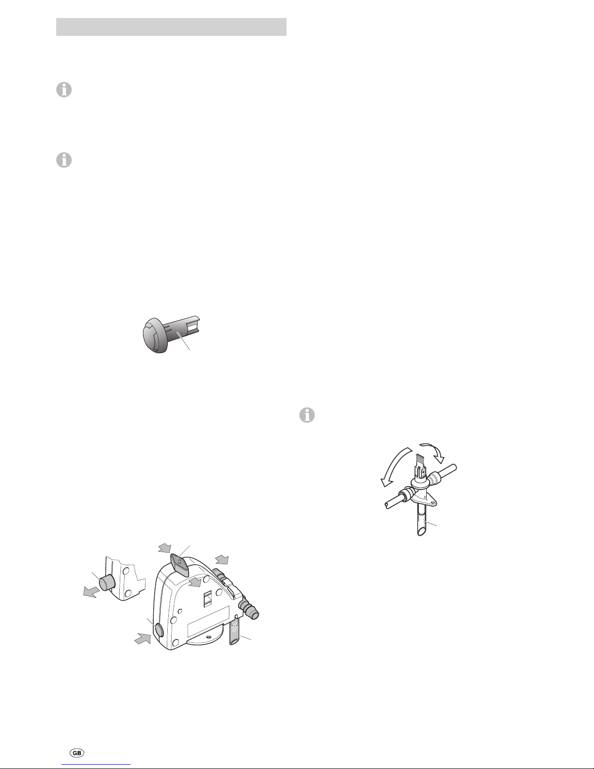
Room temperature sensor
To measure the room temperature, an external room temperature sensor (2) is located in the vehicle. The position of the
sensor is determined by the vehicle manufacturer depending
on the vehicle model. More information can be found in the
operating instructions for your vehicle.
2
Figure 2
The temperature setting on the control panel depends on personal heating requirements and the design of the vehicle, and
must be determined individually.
Safety/drain valve
A. FrostControl
(Safety/drain valve with integral frost protection / optional in
UK version)
FrostControl is a currentless safety/drain valve. When there
is a danger of frost, it automatically drains the contents of
the boiler through a drainage socket. If excessive pressure is
present in the system, pressure will be automatically intermittently equalized through the pressure relief valve.
a
b
c
d
Figure 3
a = rotary switch position “On”
b = pushbutton position “Closed”
c = pushbutton position “Drain”
d = drainage socket (led outside through floor of vehicle)
Opening the safety/drain valve
– Turn the rotary switch by 180° until it engages, whereby the
pushbutton pops out (position c). The water from the boiler
drains through the drainage socket (d).
The FrostControl drainage socket (d) must be free of contamination (slush, ice, leaves, etc.) at all times so the water can
drain out easily! No claims may be made under the war-
ranty for damage caused by frost.
Closing the safety/drain valve
– Check whether the rotary switch is set to “On” (position a),
i.e. parallel to the water connection and engaged.
– Close the safety/drain valve by pressing the pushbutton.
The pushbutton must engage in position (b) “closed”.
Only when the temperature at the safety/drain valve is above
approx. 7 °C can it be closed manually with the pushbutton
(position b) and the boiler filled.
Truma supplies a heating element (part no. 70070-01) as an
accessory, which is inserted into the FrostControl and fixed
in place with a retaining bracket. This heating element heats
the FrostControl to approx. 10°C when the Combi is switched
on.This means that the boiler can be filled sooner, irrespective
of the temperature in the installation compartment.
Automatic opening of the safety/drain valve
If the temperature at the safety/drain valve is below about
3 °C, it will open automatically and the pushbutton pops out
(position c). The water from the boiler drains through the
drainage socket (d).
B. Safety/drain valve
(Safety/drain valve without frost protection /
standard in UK version)
The safety/drain valve automatically equalises the pressure in
the event of overpressure in the system. When this occurs,
the water is drained to the outside in intermittent bursts via a
drainage socket.
This safety/drain valve does not protect the water container from frost damage.
c
b
a
d
Figure 4
a = Lever in position “Operational – closed”
b = Lever in position “Operational – closed”
c = Lever in position “Drain”
d = Drainage socket (led outside through floor of vehicle)
Opening the safety/drain valve
– Move lever to position (c) – vertical. The water from the
boiler drains through the drainage socket (d).
The drainage socket (d) of the safety/drain valve must be free
of contamination (slush, ice, leaves, etc.) at all times so the
water can drain out easily! No claims may be made under
the warranty for damage caused by frost!
Closing the safety/drain valve
– Move lever to position (a) or (b) – horizontal.
Operating instructions
Page 7

7
Filling the boiler
Check whether the safety/drain valve is closed (see “Closing
the safety/drain valve”).
When the temperature at FrostControl is below approx.
7 °C, first switch on the heater to warm the installation
compartment and FrostControl. After several minutes, when
the temperature at FrostControl is above 7 °C, the safety/drain
valve can be closed.
– Switch on the power for the pump assembly (main switch
or pump switch).
– Open hot water taps in the kitchen and bathroom (set pre-
selecting mixing taps or single-lever fittings to “hot”). Leave
the valves open until the boiler has been filled by displacing
the air and water is flowing without interruption.
If only the cold water system is being operated without
the boiler, the boiler also fills up with water. To avoid
frost damage, the boiler must be drained via the safety/drain
valve, even if it was not operated.
In the event of frost, filling may be prevented by frozen residual
water. The boiler can be thawed by turning it on briefly (no
more than 2 minutes). Frozen lines can be thawed by heating
the interior.
If the boiler is connected to a central water supply (rural
or urban connection), a pressure reducer must be used,
which will prevent pressures higher than 2.8 bar from
occurring.
Draining the boiler
The boiler must be drained if the motor home / caravan
is not being used during the frosty period.
– Switch off the power to the pump assembly (main switch or
pump switch).
– Open hot water taps in kitchen and bathroom.
In order to check the water that is flowing out, place an
appropriate container (capacity 10 litres) beneath the
drainage socket (d) of the safety/drain valve.
– Open safety/drain valve
(see “Opening the safety/drain valve”).
The boiler will now be drained directly to the outside via the
safety/drain valve. Check whether all of the water in the boiler
(10 litres) has been drained into the container via the safety/
drain valve.
No claims may be made under the warranty for damage
caused by frost.
Start-up
Combi
The interior can be heated either with or without water, depending on the setting.
Combi E
The interior can be heated in gas, electrical or mixed mode,
either with or without water, depending on the setting.
Check whether the power supply fuse protection at
the camp site is adequate for the 900 W (3.9 A) or
1800 W(7.8 A) that have been selected using the power
selector switch.
The cable drum must be fully unwound in order to prevent
the power cable from overheating.
– Check to make sure the cowl is unobstructed. Be sure to
remove any covers that may be present.
– Open the gas cylinder and the quick-acting valve in the gas
supply line.
– Fill boiler with water if necessary (see “Filling the boiler”).
– Switch on the unit on the control panel.
Switching off
– Switch the heater off on the control panel.
– The switch-off procedure may be delayed by several min-
utes because of internal heater operations.
Always drain water contents if there is a risk of frost!
If the appliance is not used for a long period, close the quickacting valve in the gas supply line and the gas cylinder.
Maintenance
Only original Truma parts may be used for maintenance and
repair work.
– Clean the compartment where the unit is installed at least
once annually.
– Have an expert check the unit for dirt and clean it if
necessary.
– The safety/drain valve must be operated regularly (at least
twice annually) to remove limescale deposits and to be certain that it is not blocked.
We recommend the use of suitable commercially available
products to clean, sterilise and maintain the boiler. Products
containing chlorine are not suitable.
The effectiveness of the use of chemicals to combat microorganisms in the appliance can be increased by heating the
water in the boiler to 70°C at regular intervals.
Combi E only
– Select “Gas mode”.
– Set the water temperature to 60 °C.
– Switch on the appliance.
Once the water in the boiler has reached a temperature
of 60 °C, the burner will switch off. The appliance must
stay switched on for at least 30 minutes and no hot water
may be removed. The residual heat in the heat exchanger will
heat the water up to 70 °C.
Page 8
8
Fuses
Fuse 12 V
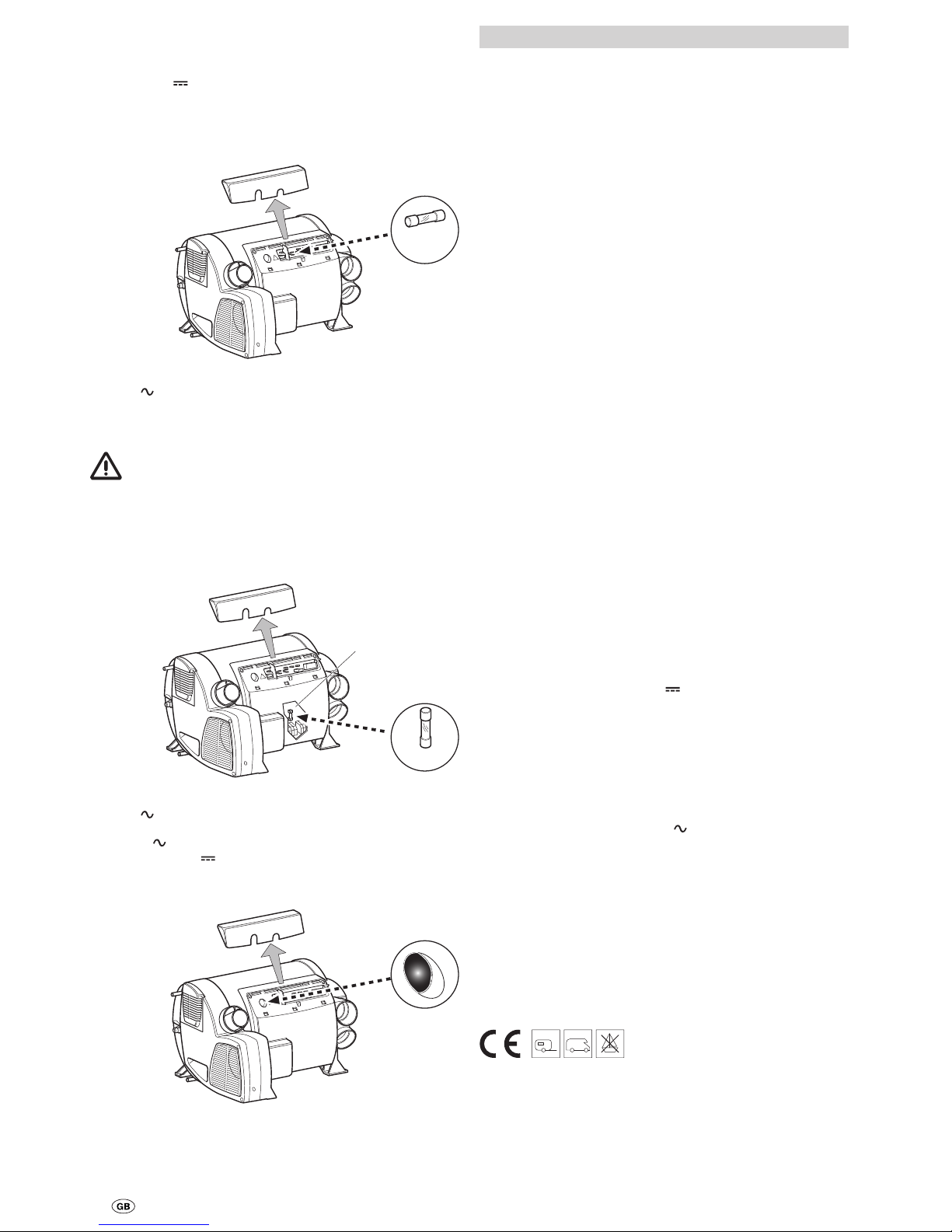
The fuse is in the electronics beneath the connection cover.
Always replace the fuse of the unit with an identical fuse.
Appliance fuse: 10 A – slow-acting – 5 x 20 mm (T 10 A)
T 10 A
Figure 5
230 V fuse (Combi E)
The fuse and the power supply lines must only be replaced by
an expert!
The unit must be disconnected from the mains (all
poles) before opening the electronic housing lid.
The fuse is in the power electronics (14) beneath the electronic housing lid.
This fine fuse must always be replaced with a fuse of the
same type: 10 A, slow-acting, interrupting capacity “H”.
T 10 A
14
Figure 6
230 V overheating protection (Combi E)
The 230 V heating facility has a mechanical overheating
switch. If the 12 V
power supply is interrupted during operation or during the after-run period, for example, the temperatures within the unit could activate the overheating protection.
Figure 7
To reset the overheating protection, allow heater to cool, remove connection cover and press red reset button.
Technical data
determined in accordance with EN 624 or Truma test
conditions
Device category
I
3 B/P
in accordance with EN 437
Type of gas
Liquid gas (propane / butane)
Operating pressure
30 mbar (see type plate)
Water capacity
10 litres
Heating time from approx. 15 °C to approx. 60 °C
Boiler approx. 20 minutes (measured according to EN 15033)
Heater + boiler approx. 80min.
Pump pressure
max. 2.8 bar
System pressure
max. 4.5 bar
Rated thermal output (automatic operating levels)
Gas mode
Combi 2 E*: 2000 W
Combi 4 (E)*: 2000 W / 4000 W
Combi 6 (E)*: 2000 W/ 4000 W/6000 W
Electrical mode
Combi 2 E* / Combi 4 E* / Combi 6 E*: 900 W / 1800 W
Mixed mode (gas and electrical)
Combi 2 E* / Combi 4 E*: max. 3800 W
Combi 6 E*: max. 5800 W
Gas consumption
Combi 2 E*: 160 g/h
Combi 4 (E)*: 160 – 320 g/h
Combi 6 (E)*: 160 – 480 g/h
Standby heat requirement (all units)
Gas mode 5.2 g/h
Destination countries
Combi 2 E*: GB, IE
Combi 4 (E)* / Combi 6 (E)*:
DE, AT, CH, DK, FI, NL, NO, SE, SK, CZ, CY, BE, IT, PT, RO,
GR, IE, LU, IS, PL, EE, LT, LV, MT, SI, HU, ES, FR, GB, BG, RU
Air delivery volume (free-blowing without warm air duct)
Combi 2 E* /
Combi 4 (E)*: With 3 warm air outlets max. 249 m³/h
With 4 warm air outlets max. 287 m³/h
Combi 6 (E)*: With 4 warm air outlets max. 287 m³/h
Power consumption at 12 V
Heater + boiler
Combi 2 E* /
Combi 4 (E)*: Max. 5.6 A for short periods
(average power consumption approx. 1.1 A)
Combi 6 (E)*: Max. 5.6 A for short periods
(average power consumption approx. 1.3 A)
Boiler heating maximum 0.4 A
Stand-by approx. 0.001 A
Heating element – FrostControl (optional): maximum 0.4 A
Power consumption at 230 V
Combi 2 E* / Combi 4 E* / Combi 6 E*
3.9 A (900 W) or 7.8 A (1800 W)
Protection class
IP 21
Weight (without water)
Heater: 15.1 kg
Heater with
peripheral devices: 15.6 kg
CE product ID number
Combi 2 E*: CE-0085CN0021
Combi 4 (E)* / Combi 6 (E)*: CE-0085BS0085
* (UK) CP plus ready
Page 9
9
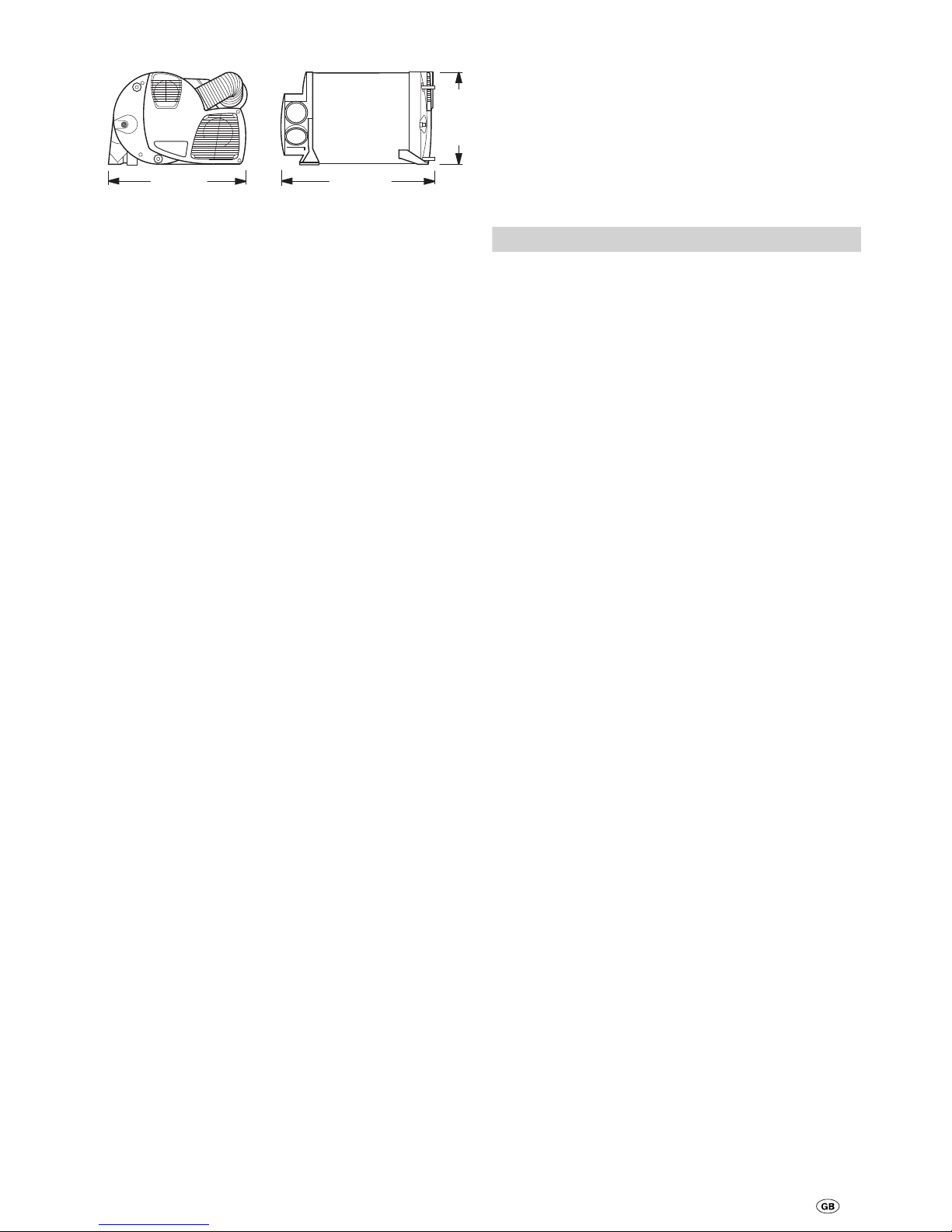
Dimensions
450 mm
510 mm
300 mm
Figure 8
Subject to technical changes.
Disposal
The appliance must be disposed of in accordance with the administrative regulations of the respective country in which it is
used. National regulations and laws (in Germany for example
the End-of-Life Vehicle Regulation) must be observed.
Faults
Faults – Heater
Descriptions of possible fault causes and a troubleshooting
guide can be found in the operating instructions for the control panel that is installed.
Faults – Water supply
Possible fault causes and a troubleshooting guide – See
“Troubleshooting guide (water supply)”.
Troubleshooting guide (water supply)
Fault Cause / Remedy
Water taking an extremely
long time to heat up.
Water container furred./
Descale water system (see
maintenance).
Water running away – boiler
cannot be filled.
Safety/drain valve open. /
Close safety/drain valve.
Boiler cannot be drained,
even though the safety/drain
valve is open.
Safety/drain valve drainage
socket blocked. / Check opening for soiling (slush, ice,
leaves etc.) and remove if
necessary.
Water dripping/flowing from
drainage socket of safety/
drain valve.
Water pressure too high. /
Check pump pressure (max.
2.8 bar). If the boiler is connected to a central water supply (rural or urban connection),
a pressure reducer must be
used that will prevent pressures higher than 2.8 bar from
occurring.
After the heater has
been switched off, the
FrostControl opens.
At temperatures of less than
approx. 3 °C the FrostControl
opens automatically / Switch
heater on / Without heater operation the FrostControl cannot be closed again until the
temperature reaches approx.
7 °C / Use heating element for
FrostControl.
The FrostControl can no
longer be closed.
Temperature at FrostControl
less than approx. 7 °C/
Switch heater on / Without heater operation the
FrostControl cannot be closed
again until the temperature
reaches approx. 7 °C.
Rotary switch is not set to
“Operation”. / Turn the rotary
switch of the FrostControl to
“Operation”, then press the
pushbutton until it engages.
If these actions do not remedy the problem, please
contact Truma Service.
Page 10
10
Manufacturer’s Warranty
(European Union)
1. Scope of Manufacturer’s Warranty
As the Manufacturer of the unit, Truma undertakes a warranty
towards the Consumer that covers any material and/or manufacturing defects of the unit.
This Warranty is applicable in EU member states as well as in
Iceland, Norway, Switzerland and Turkey. A Consumer is the
natural person who was the first one to purchase the unit from
the Manufacturer, OEM or dealer and who neither resold the
unit in a commercial or self-employed professional capacity
nor did he or she install it for a third party in such a capacity.
The Manufacturer’s Warranty covers any of the aforementioned
defects that occur within 24 months upon concluding the
purchase agreement between the seller and the Consumer.
The Manufacturer or an authorised service partner undertakes
to remedy such defects through subsequent fulfilment, i.e.
at its discretion either by repairing or replacing the defective
item. Any defective parts shall become the property of the
Manufacturer or the authorised service partner. If the unit is
no longer manufactured at the time of defect notification and
if replacement delivery has been opted for, then the Manufacturer may deliver a similar product.
If the Manufacturer remedies a defect under its warranty commitment, the term of the Warranty shall not recommence anew
with regard to the repaired or replaced parts; rather, the original warranty period shall continue to be applicable to the unit.
Only the Manufacturer itself and an authorised service partner
shall be entitled to conduct a warranty job. Any costs that occur in the event of a warranty claim shall be settled directly
between the authorised service partner and the Manufacturer.
The Warranty does not cover additional costs arising from
complicated removal or installation jobs on the unit (e.g. dismantling of furnishings or parts of the vehicle body), and neither does it cover travel expenses incurred by the authorised
service partner or the Manufacturer.
No further-reaching claims shall be permitted, especially damage claims presented by the Consumer or third parties. This
provision shall not affect the validity of the German Product
Liability Act (Produkthaftungsgesetz).
Neither does the voluntary Manufacturer’s Warranty affects
the Consumer’s legally applicable claims for defects towards
the seller in the relevant country of purchase. In individual
countries there may be warranties that can be issued by the
relevant dealer (official distributor, Truma Partner). In such
cases the warranty can be implemented directly through the
dealer from whom the Consumer bought the unit. The warranty regulations of the country in which the unit was purchased
by the Consumer for the first time shall also be applicable.
2. Warranty exclusions
No warranty claim shall be applicable under the following
circumstances:
– Improper use, contrary to the specified use
– Improper installation, assembly or commissioning, contrary
to operating or installation instructions
– Improper operation, contrary to operating or installation
instructions, particularly maintenance, care and warning
notes
– Instances where repairs, installations or any other proce-
dures have been conducted by non-authorised partners
– Consumable materials and parts which are subject to natu-
ral wear and tear
– Installation of replacement, supplementary or accessory
parts that are not original Manufacturer’s parts and which
have thus caused a defect
– Damage arising from foreign substances (e.g. oils, plasticis-
ers in the gas), chemical or electrochemical influences in
the water, or cases when the unit has come into contact
with unsuitable substances (e.g. chemical products, unsuitable cleaning agents)
Accessories
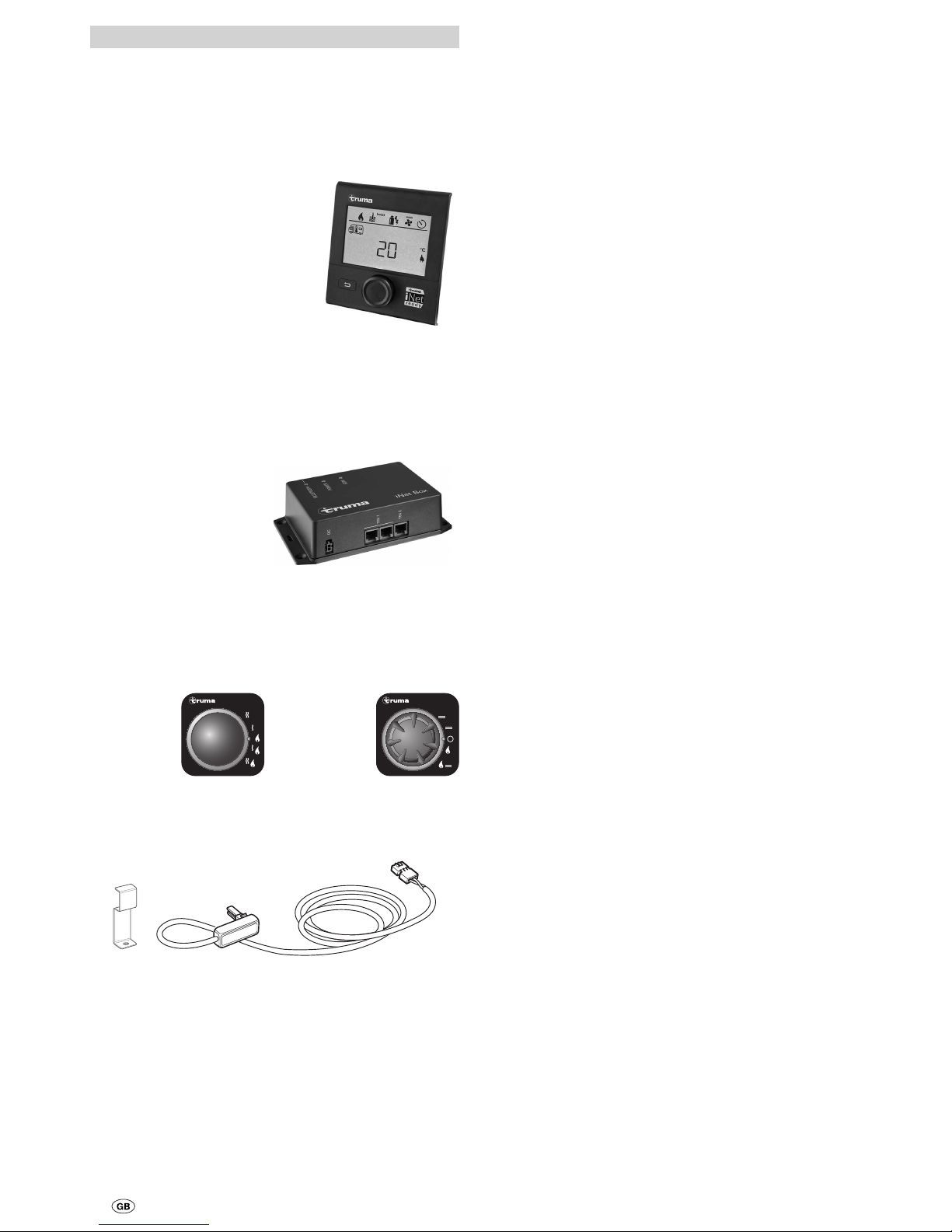
Truma CP plus
Truma CP plus digital control panel with automatic air conditioning system for the iNet-capable Truma heaters
Combi and Truma air conditioning systems Aventa eco,
Aventa comfort (from serial number 24084022 – 04/2013),
Saphir comfort RC and Saphir compact (from serial number
23091001 – 04/2012)
– The automatic air condi-
tioning system function
automatically controls the
heater and the air conditioning system until the
required temperature is
reached in the vehicle.
– With the Truma iNet Box
extension, all TIN-Buscapable Truma appliances
can also be controlled via
the Truma App.
Figure 9
Truma iNet Box
The Truma iNet Box for simple networking and control of
Truma appliances with a smartphone or tablet computer using
the app.
– Simple installation and
start-up via the Truma App
– Can be extended with the
update function, which
ensures that it is always up
to date
Figure 10
Truma CP E classic / Truma CP classic
Analogue control panels Truma CP E classic (power selector
switch – Fig. 11) and Truma CP classic (control panel – Fig.12).
Fig. 11
Combi E
230 V~
Fig. 12
1
3
5
7
9
40
°
60
°
60
°
Combi
1
2
3
4
5
Heating element for FrostControl
Heating element with 1.5 m connector cable and retaining
bracket.
Fig. 13
Other accessories (not illustrated) for control panels
– Cable available in different lengths
Page 11

11
– Damage caused by abnormal environmental or unsuitable
operating conditions
– Damage caused by force majeure or natural disasters or
any other influences not within Truma’s responsibility
– Damage resulting from improper transport
3. Making a warranty claim
The warranty must be claimed with an authorised service partner or at the Truma Service Centre. All the relevant addresses
and phone numbers can be found at www.truma.com, in the
“Service” section.
To ensure a smooth procedure, we should be grateful if you
could have the following details ready before contacting us:
– Detailed description of the defect
– Serial number of the unit
– Date of purchase
The authorised service partner or the Truma Service Centre
will then specify the further procedure. To avoid transport
damage, the affected unit must only be shipped upon prior
arrangement with the authorised service partner or the Truma
Service Centre.
If the warranty claim is recognised by the Manufacturer, then
the transport expenses shall be borne by the same. If no warranty claim is applicable, the Consumer will be notified accordingly and any repair and transport expenses shall then be
the Consumer’s liability. We must ask you not to send in a unit
without prior arrangement.
Page 12

Bei Störungen wenden Sie sich bitte an das Truma
Servicezentrum oder an einen unserer autorisierten
Servicepartner (siehe www.truma.com).
Für eine rasche Bearbeitung halten Sie bitte Gerätetyp
und Seriennummer (siehe Typenschild) bereit.
Should problems occur, please contact the Truma
Service Centre or one of our authorised service
partners (see www.truma.com).
In order to avoid delays, please have the unit model
and serial number ready (see type plate).
Veuillez vous adresser au centre de SAV Truma ou
à un de nos partenaires de SAV agréés en cas de
dysfonctionnements (voir www.truma.com).
Pour un traitement rapide de votre demande, veuillez
tenir prêts le type d’appareil et le numéro de série
(voir plaque signalétique).
In caso di guasti rivolgersi al centro di assistenza
Truma o a un nostro partner di assistenza autorizzato
(consultare il sito www.truma.com).
Affinché la richiesta possa essere elaborata rapidamente,
tenere a portata di mano il modello dell’apparecchio e
il numero di matricola (vedere targa dati).
Bij storingen kunt u contact opnemen met het
Truma Servicecentrum of met een van onze erkende
servicepartners (zie www.truma.com).
Voor een snelle bediening dient u apparaattype en
serienummer (zie typeplaat) gereed te houden.
Ved fejl kontaktes Trumas serviceafdeling eller en af
vores autoriserede servicepartnere (se www.truma.com).
Sørg for at have oplysninger om apparattype og
serienummer (se typeskiltet) klar for hurtig behandling.
Vid fel kontakta Truma servicecenter eller någon av
våra auktoriserade servicepartner (se www.truma.com).
För snabb handläggning bör du ha aggregatets typ och
serienummer (se typskylten) till hands.
Truma Gerätetechnik GmbH & Co. KG
Wernher-von-Braun-Straße 12
85640 Putzbrunn
Deutschland
Service
Telefon +49 (0)89 4617-2020
Telefax +49 (0)89 4617-2159
[email protected]
www.truma.com
Las instrucciones de uso y de montaje en su idioma
pueden solicitarse al fabricante Truma o al Servicio
postventa Truma en su país.
Saat käyttö- ja asennusohjeen pyynnöstä omalla
kielelläsi valmistajalta (Truma) tai maasi Truma-huoltoon.
Spør om bruks- og monteringsanvisning på norsk hos
produsenten Truma eller Trumas serviceavdeling i
landet ditt.
Μπορείτε να ζητήσετε τις οδηγίες χρήσης και
τοποθέτησης στη γλώσσα της χώρας σας από τον
κατασκευαστή Truma ή από το σέρβις της Truma στη
χώρα σας.
Návod k použití a montáži si lze v jazyce vaší země
vyžádat u výrobce Truma nebo servisu Truma ve vaší
zemi.
Návod na použitie a montáž vo Vašom štátnom jazyku
si môžete vyžiadať u výrobcu Truma alebo v servise
Truma vo Vašej krajine.
As instruções de utilização e montagem podem ser
solicitadas junto do fabricante Truma ou do serviço de
assistência da Truma no seu país.
Az Ön nyelvén a használati és beszerelési utasítás
a Truma gyártójától vagy az adott ország Truma
szerviztől szerezhető be.
Instrukcję obsługi i montażu we właściwej wersji
językowej można otrzymać w firmie Truma lub serwisie
firmy Truma znajdującym się w danym kraju.
Navodila za uporabo in vgradnjo v vašem jeziku lahko
naročite pri proizvajalcu Truma oz. v servisni službi
podjetja Truma v vaši državi.
TR
Dilinizdeki kullanma ve montaj talimatı, üretici
Truma'dan veya ülkenizdeki Truma servisinden talep
edilebilir.
Руководство по эксплуатации и монтажу на
Вашем национальном языке можно запросить
у изготовителя Truma или в сервисной службе
фирмы Truma в Вашей стране.
34030-11600 · 05 · 02/2017 ·
©
 Loading...