


Trumatic C
40°
60°
60°
1
3
5
7
9
Trumatic C EL
230 V ~
Trumatic
C 3402
C 6002
Navodila za uporabo in vgradnjo v Vašem jeziku lahko
zahtevate pri izdelovalcu Truma ali servisu Truma v Vaši
državi.
Istruzioni per l’uso Pagina 18
Da tenere nel veicolo!
Gebrauchsanweisung
Seite 2
Im Fahrzeug mitzuführen!
Operating instructions Page 7
To be kept in the vehicle!
Mode d’emploi Page 12
À garder dans le véhicule !
Gebruiksaanwijzing
Pagina 24
In voertuig meenemen!
Brugsanvisning
Side 29
Skal medbringes i køretøjet!
Instrucciones de uso Página 34
¡Ilévalas en el vehículo!
Bruks- och monteringsanvisningar på svenska
kan rekvireras från tillverkaren Truma eller från
Truma-Service i Sverige.
Käyttö- ja asennusohjeita on saatavissa
Truma-valmistajalta tai Truma-huollosta.
Bruksanvisningen og monteringsveiledningen
på ditt språk kan fås hos produsenten Truma
eller hos Truma-Service i ditt land.
Τις οδηγίες χρήσης και τοποθέτησης στη µητρική σας
γλώσσα µπορείτε να τις λάβετε απ τον κατασκευαστή
Truma ή απ το σέρβις Truma στη χώρα σας.
Instruções de utilizaçaõ e de montagem podem
ser solicitadas junto ao fabricante Truma ou da
assistência técnica da Truma no seu país.
Návod k použití a montáži ve svém jazyce obdržíte
na požádání u firmy Truma nebo u jejího servisního
zástupce ve vaší zemi.
A magyar nyelvü használati és szerelési utasítást
a gyártónál a Truma cégnél vagy a Truma
magyarországi képviseleténél lehet beszerezni.
Instrukcję obsługi i montażu w ojczystym
języku mogą Państwo dostać u producenta
(Truma) lub w serwisie Trumy w swoim kraju.
Truma Gerätetechnik
GmbH & Co. KG
Wernher-von-Braun-Straße 12
D-85640 Putzbrunn bei München
Service
Telefon +49 (0)89 4617-142
Telefax +49 (0)89 4617-159
info@truma.com
www.truma.com

2
1 Kaltwasseranschluss
2 Warmwasseranschluss
3 Gasanschluss
4 Warmluftaustritte
5 Umluft-Rückführung
6 Abgas-Abführung
7 Verbrennungsluft-
Zuführung
8 Elektronische
Steuereinheit
9 Abdeckung für
Anschlusskabel
Funktionsbeschreibung
Die Trumatic C ist eine
Warmluft-Flüssiggasheizung
mit integriertem Warmwasserboiler (12 Liter Inhalt). Der
Brenner arbeitet gebläseunterstützt, dadurch ist eine einwandfreie Funktion auch
während der Fahrt sichergestellt. Zum Betrieb während
der Fahrt müssen nationale
Einschränkungen berücksichtigt werden.
Im Winterbetrieb (Heizung
und Warmwasser) wählt das
Gerät automatisch die benötigte Leistungsstufe, entsprechend der Temperaturdifferenz zwischen eingestellter
und gegenwärtiger Raumtemperatur. Der Typ C 6002
arbeitet in drei Leistungsstufen (2000, 4000 und 6000 W),
der Typ C 3402 in zwei Leistungsstufen (2000 und
3400 W). Bei gefülltem Boiler
wird das Wasser automatisch
mitgeheizt. Die Wassertemperatur ist von der gewählten
Betriebsart (mit oder ohne
Warmwasseranforderung)
und der Heizleistungsabgabe
abhängig.
Der Heizbetrieb ist
grundsätzlich sowohl
mit wie auch ohne Wasserinhalt uneingeschränkt
möglich.
Im Sommerbetrieb (nur
Warmwasser) erfolgt die Aufheizung des Wasserinhaltes
in der kleinsten Brennerstufe.
Ist die Wassertemperatur erreicht, schaltet der Brenner
ab und die gelbe Kontrolllampe erlischt.
Die Heizgeräte Trumatic C EL
haben als Option eine zusätzliche Elektrobeheizung 230 V
(450 W/2 A) für Warmwasser.
Wichtige
Bedienungshinweise
1. Falls der Kamin in der
Nähe bzw. direkt unterhalb
eines zu öffnenden Fensters
platziert wurde, muss das
Gerät mit einer selbsttätigen
Abschaltvorrichtung versehen sein, um einen Betrieb
bei geöffnetem Fenster zu
verhindern.
2. Das Abgas-Doppelrohr
muss regelmäßig, insbesondere nach längeren Fahrten,
auf Unversehrtheit und festen
Anschluss überprüft werden,
ebenso die Befestigung des
Gerätes und des Kamins.
3. Nach einer Verpuffung
(Fehlzündung) Abgasführung
vom Fachmann überprüfen
lassen!
4. Der Kamin für Abgasführung und Verbrennungsluftzufuhr muss immer frei von
Verschmutzungen gehalten
werden (Schneematsch, Eis,
Laub etc.).
5. Der eingebaute Temperaturbegrenzer sperrt die Gaszufuhr, wenn das Gerät zu
heiß wird. Die Warmluftauslässe und die Öffnung für die
Umluft-Rückführung dürfen
deshalb nicht verschlossen
werden.
6. Bei in Kraftfahrzeugen eingebauten Flüssiggasheizungen muss in Deutschland
gemäß § 22a StVZO der Wärmetauscher erst nach einer
Betriebsdauer von 30 Jahren
ersetzt werden (das Jahr der
ersten Inbetriebnahme muss
auf dem Fabrikschild dauerhaft eingetragen sein).
Für Wartungs- und Reparaturarbeiten dürfen nur
Original-Truma-Ersatzteile
verwendet werden.
10 Wasserbehälter (12 l)
11 Zünder
12 Brenner
13 Wärmetauscher
14 Überhitzungsschutz
15 Temperaturfühler
16 Heizmanschette 230 V
für Warmwasser
(nur Trumatic C EL)
17 Bedienteile
18 Raumtemperaturfühler

3
Gebrauchsanweisung
Vor Inbetriebnahme unbedingt Gebrauchsanweisung
und „Wichtige Bedienungshinweise“ beachten!
Der Fahrzeughalter ist dafür
verantwortlich, dass die Bedienung des Gerätes ordnungsgemäß erfolgen kann.
Der dem Gerät beigegebene
gelbe Aufkleber mit den
Warnhinweisen muss durch
den Einbauer bzw. Fahrzeughalter an einer für jeden Benutzer gut sichtbaren Stelle
im Fahrzeug (z.B. an der Kleiderschranktür) angebracht
werden! Fehlende Aufkleber
können bei Truma angefordert werden.
Vor dem ersten Ge-
brauch unbedingt die
gesamte Wasserversorgung
mit erwärmtem klarem Wasser gut durchspülen. Wenn
die Heizung nicht betrieben
wird, Wasserinhalt bei Frostgefahr unbedingt entleeren!
Kein Garantieanspruch für
Frostschäden! Ebenso vor
Reparaturen bzw. Wartungsarbeiten am Fahrzeug (in
Werkstätten!) Wasserinhalt
entleeren, da bei stromlosem
Zustand das elektrische
Sicherheits-/Ablassventil
automatisch öffnet!
Elektrisches
Sicherheits-/
Ablassventil
m= Betätigungsknopf
„geschlossen“
n = Betätigungsknopf
„entleeren“
Das Ablassventil wird
mittels einer elektrischen Spule im geschlossenen Zustand gehalten. Um
die Batterie nicht unnötig zu
belasten, wird empfohlen,
das Ablassventil bei längerem
Nichtgebrauch zu öffnen!
Bei tieferen Temperaturen als
4°C am Sicherheits-/Ablassventil kann der Wasserinhalt
des Boilers von selbst ablaufen, wenn das Gerät nicht in
Betrieb ist (auch bei Störung)!
Zur Vermeidung von Wasserverlust das Gerät einschalten
(Sommer- oder Winterbetrieb)
und das Sicherheits-/Ablassventil am Betätigungsknopf
durch Hochziehen wieder
schließen (Stellung m).
Ohne Heizbetrieb lässt sich
das Sicherheits-/Ablassventil
erst bei Temperaturen über
8°C wieder verschließen!
Der Entleerungsstutzen des
elektrischen Sicherheits-/Ablassventils muss immer frei
von Verschmutzungen
(Schneematsch, Eis, Laub etc.)
gehalten werden! Kein Garan-
tieanspruch für Frostschäden!
Füllen des Boilers
1. Elektrisches Sicherheits-/
Ablassventil am Betätigungsknopf durch Hochziehen
schließen (Stellung m).
Bei Temperaturen um 8°C und
darunter erst Heizung oder
Boiler einschalten, damit das
Ventil nicht wieder öffnet!
2. Strom für Wasserpumpe
einschalten (Haupt- oder
Pumpenschalter).
3. Warmwasserhähne in
Küche und Bad öffnen (Vorwahlmischer oder Einhebelarmaturen auf „warm“ stellen). Die Armaturen so lange
geöffnet lassen, bis der Boiler
durch Verdrängen der Luft
gefüllt ist und Wasser fließt.
Wird nur die Kaltwas-
seranlage ohne Boiler
betrieben, füllt sich auch hier
der Boilerkessel mit Wasser.
Um Frostschäden zu vermeiden, muss der Wasserinhalt
durch Betätigen des Sicherheits-/Ablassventils abgelassen werden, auch wenn der
Boiler nicht betrieben wurde.
Als Alternative können zwei
heißwasserbeständige Absperrventile vor dem Kaltund Warmwasseranschluss
montiert werden.
Bei Anschluss an eine
zentrale Wasserversorgung (Land- bzw. City-Anschluss) muss ein Druckminderer eingesetzt werden, der
verhindert, dass höhere
Drücke als 2,8 bar im Boiler
auftreten können.
Entleeren des Boilers
1. Strom für Wasserpumpe
unterbrechen (Haupt- oder
Pumpenschalter).
2. Warmwasserhähne in
Küche und Bad öffnen.
3. Elektrisches Sicherheits-/
Ablassventil am Betätigungs-
knopf durch Eindrücken öffnen (Stellung n).
Der Boiler wird jetzt über das
Sicherheits-/Ablassventil direkt nach außen entleert.
Durch Unterstellen eines entsprechenden Eimers prüfen,
ob der Wasserinhalt vollständig abläuft (12 Liter). Kein
Garantieanspruch für
Frostschäden!
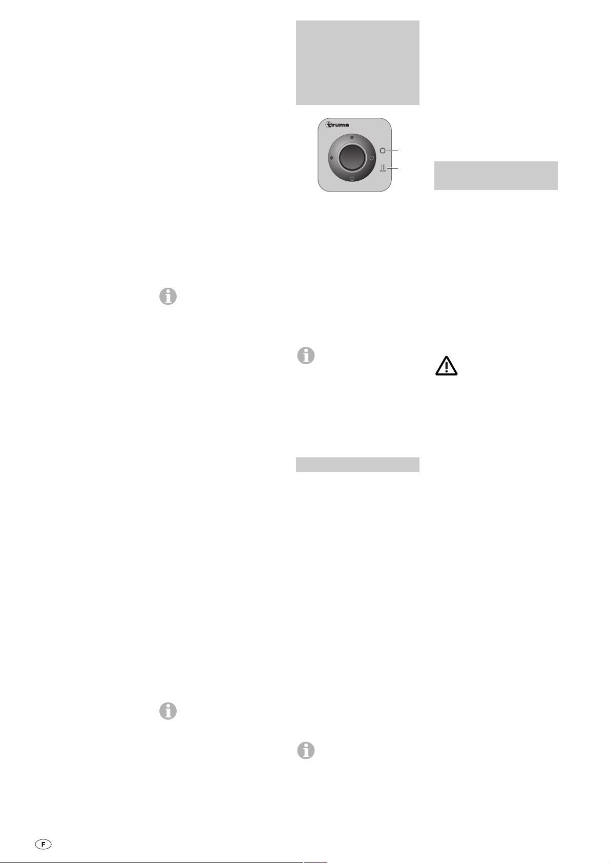
Gasbetrieb (Heizen
und Warmwasser)
a = Drehknopf für Raum-
temperatur (1 – 9)
b = grüne Kontrolllampe
„Betrieb“
c = Sommerbetrieb (Wasser-
temperatur 40°C oder
60°C)
d = Winterbetrieb (Heizen
ohne Warmwasseranforderung)
e = Winterbetrieb (Heizen mit
Warmwasseranforderung)
f = Drehschalter „Aus“
g = gelbe Kontrolllampe
„Boiler Aufheizphase“
h = rote Kontrolllampe
„Störung“
Bei Verwendung von fahrzeugspezifischen Schaltern:
siehe Bedienungsanleitung
des Fahrzeugherstellers.
Raumthermostat
i = Raumtemperaturfühler
Zur Messung der Raumtemperatur befindet sich im Fahrzeug ein externer Raumtemperaturfühler (i). Die Lage des
Fühlers wird vom Fahrzeughersteller, je nach Fahrzeugtyp, individuell abgestimmt.
Näheres entnehmen Sie bitte
der Bedienungsanleitung
Ihres Fahrzeuges.
Die Thermostateinstellung
am Bedienteil (1 – 9) muss
nach Wärmebedürfnis und
Bauart des Fahrzeuges individuell ermittelt werden. Für eine mittlere Raumtemperatur
von ca. 23°C empfehlen wir
eine Thermostateinstellung
von ca. 6 – 8.
i
Trumatic C
40°
60°
60°
1
3
5
7
9
c
d
f
h
a
g
e
b
Inbetriebnahme
1. Überprüfen, ob der Kamin
frei ist. Etwaige Abdeckungen unbedingt entfernen, bei
Verwendung auf Booten
Deckskamin öffnen.
Im Winter empfiehlt sich
beim Dachkamin die Verwendung der Kaminverlängerung
(siehe Zubehör). Diese muss
während der Fahrt abgenommen werden. Zur Durchführung des Kamins durch
ein Überdach bei Caravans
wird ebenfalls eine Kaminverlängerung verwendet. Diese
muss mit Klemmringen (siehe
Zubehör) am Überdach fixiert
werden.
2. Gasflasche und Schnellschlussventil in der Gaszuleitung öffnen.
Der Heizbetrieb ist
grundsätzlich sowohl
mit wie auch ohne
Wasserinhalt uneingeschränkt möglich.
Sommerbetrieb
(nur Warmwasser)
Drehschalter auf Sommerbetrieb (c) 40°C oder 60°C stellen.
Nach Erreichen der eingestellten Wassertemperatur
(40°C oder 60°C) schaltet der
Brenner ab und die gelbe
Kontrolllampe (g) erlischt.
Winterbetrieb
Heizen mit
WarmwasserAnforderung
1. Drehknopf (a) auf die gewünschte Thermostatstellung
(1 – 9) drehen. Nach dem
Einschalten leuchtet die grüne Kontrolllampe (b) und
zeigt die Stellung der eingestellten Raumtemperatur.
2. Drehschalter auf Betriebsstellung „e“ stellen.
Das Gerät wählt automatisch
die benötigte Leistungsstufe,
entsprechend der Temperaturdifferenz zwischen eingestellter und gegenwärtiger
Raumtemperatur. Nach Erreichen der am Bedienteil eingestellten Raumtemperatur
schaltet der Brenner zurück
auf die kleinste Stufe und
heizt den Wasserinhalt auf
60°C. Die gelbe Kontrolllampe (g) zeigt die Aufheizphase
an und erlischt nach Erreichen der Wassertemperatur.

4
Heizen ohne
WarmwasserAnforderung
1. Drehknopf (a) auf die gewünschte Thermostatstellung
(1 – 9) drehen. Nach dem
Einschalten leuchtet die grüne Kontrolllampe (b) und
zeigt die Stellung der eingestellten Raumtemperatur.
2. Drehschalter auf Betriebsstellung „d“ stellen.
Das Gerät wählt automatisch
die benötigte Leistungsstufe,
entsprechend der Temperaturdifferenz zwischen eingestellter und gegenwärtiger
Raumtemperatur. Nach Erreichen der am Bedienteil eingestellten Raumtemperatur
schaltet die Heizung (unabhängig von der Wassertemperatur) ab.
Bei gefülltem Boiler wird das
Wasser automatisch mitgeheizt. Die Wassertemperatur
ist dann abhängig von der abgegebenen Heizleistung und
der Heizdauer für das Erreichen der Raumtemperatur.
In dieser Betriebsstellung
leuchtet die gelbe Kontrolllampe (g – Boiler Aufheizphase)
nur bei Wassertemperaturen
von unter 5°C!
Der Heizbetrieb ist
grundsätzlich sowohl
mit wie auch ohne Wasserinhalt uneingeschränkt
möglich.
Ausschalten
„Gasbetrieb“
Heizung am Drehschalter
ausschalten (f).
Wasserinhalt bei Frostgefahr unbedingt entleeren!
Wird das Gerät längere Zeit
nicht benutzt, Schnellschlussventil in der Gaszuleitung und
Gasflasche schließen.
Rote Kontrolllampe
„Störung“
Bei einer Störung leuchtet die
rote Kontrolllampe (h) auf.
Mögliche Ursachen entnehmen Sie bitte der Fehlersuchanleitung.
Die Entriegelung erfolgt durch
Ausschalten und erneutes
Einschalten.
Wird der Fensterschal-
ter geöffnet und wieder
geschlossen, entspricht dies
einem Aus/Ein am Bedienteil
(z.B. bei Störungsreset)!
Elektrobetrieb 230 V
(450 W/2 A )
– nur Trumatic C EL –
(nur Warmwasser)
j = Wippschalter „Ein“
k = Wippschalter „Aus“
Boiler am Bedienteil einschalten (j). Die Kontrolllampe
zeigt an, dass das Gerät in
Betrieb ist.
Bei Verwendung von fahrzeugspezifischen Schaltern:
siehe Bedienungsanleitung
des Fahrzeugherstellers.
Die Wassertemperatur
ist nicht vorwählbar,
automatische Temperaturbegrenzung bei ca. 60°C! Um
eine schnellere Aufheizung
des Boilerinhaltes zu erreichen, kann das Gerät gleichzeitig mit Gas und Strom be-
trieben werden.
Wartung
Der verwendete Wasserbehälter besteht aus lebensmittelechtem Edelstahl.
Zur Entkalkung des Boilers
verwenden Sie Weinessig,
welcher über den Wasserzulauf in das Gerät gebracht
wird. Entsprechend einwirken
lassen und danach Boiler
gründlich mit Frischwasser
durchspülen. Für eine Entkeimung empfehlen wir „CertisilArgento“, andere (insbesondere chlorhaltige) Produkte
sind ungeeignet.
Um eine Besiedelung durch
Mikroorganismen zu vermeiden, ist der Boiler in regelmäßigen Abständen auf 70°C
aufzuheizen (nur im Winterbetrieb erreichbar).
Abhängig von der Heiz-
leistung für das Erreichen der Raumtemperatur,
kann das Wasser auf bis zu
70°C aufgeheizt werden.
Das Wasser nicht als Trinkwasser verwenden!
Trumatic C EL
230 V ~
k
j
Sicherungen
Die Gerätesicherung befindet
sich auf der elektronischen
Steuereinheit am Gerät.
Die Feinsicherung darf nur
gegen eine baugleiche Sicherung ausgetauscht werden.
C 3402: 4 AT – träge –
C 6002: 6,3 AT – träge –
Allgemeine
Sicherheitshinweise
Bei Undichtigkeiten der Gasanlage bzw. bei Gasgeruch:
– alle offenen Flammen
löschen
– nicht rauchen
– Geräte ausschalten
– Gasflasche schließen
– Fenster und Türe öffnen
– keine elektrischen Schalter
betätigen
– die gesamte Anlage von
einem Fachmann über-
prüfen lassen!
Reparaturen dürfen
nur vom Fachmann
durchgeführt werden!
Nach jeder Demontage der
Abgasführung muss ein neuer O-Ring montiert werden!
1. Jede Veränderung am Gerät, einschließlich Abgasführung und Kamin, oder die
Verwendung von Ersatzteilen
und funktionswichtigen Zubehörteilen, die keine Original-Truma-Teile sind, sowie
das Nichteinhalten der Einbau- und Gebrauchsanweisung führt zum Erlöschen der
Garantie sowie zum Ausschluss von Haftungsansprüchen. Außerdem erlischt die
Betriebserlaubnis des Gerätes
und dadurch in manchen
Ländern auch die Betriebserlaubnis des Fahrzeuges.
2. Der Betriebsdruck der Gasversorgung 30 mbar (bzw.
28 mbar Butan/37 mbar Propan) oder 50 mbar muss mit
dem Betriebsdruck des Gerätes (siehe Fabrikschild) übereinstimmen.
3. Flüssiggasanlagen müssen
den technischen und administrativen Bestimmungen des
jeweiligen Verwendungslandes entsprechen (in Europa
z.B. EN 1949 für Fahrzeuge
oder EN ISO 10239 für Boote). Nationale Vorschriften
und Regelungen (in Deutschland z.B. das DVGW-Arbeitsblatt G 607 für Fahrzeuge
oder G 608 für Boote) müssen beachtet werden.
Die Prüfung der Gasanlage
muss alle 2 Jahre von ei-
nem Fachmann wiederholt
werden und gegebenenfalls
in der Prüfbescheinigung (in
Deutschland z.B. gemäß
DVGW-Arbeitsblatt G 607 für
Fahrzeuge oder G 608 für
Boote) bestätigt werden.
Verantwortlich für die Veranlassung der Überprüfung
ist der Fahrzeughalter.
4. Flüssiggasgeräte dürfen
beim Tanken, in Parkhäusern,
Garagen oder auf Fähren
nicht benutzt werden.
5. Bei erster Inbetriebnahme
eines fabrikneuen Gerätes
(bzw. nach längerer Stillstandzeit) kann kurzzeitig eine leichte Rauch- und
Geruchsentwicklung auftreten. Es ist zweckmäßig, das
Gerät im Sommerbetrieb
(60°C) mehrmals aufzuheizen
und für gute Durchlüftung
des Raumes zu sorgen.
6. Ein ungewohntes Brennergeräusch oder Abheben der
Flamme lässt auf einen Reglerdefekt schließen und
macht eine Überprüfung des
Reglers notwendig.
7. Wärmeempfindliche Gegenstände (z.B. Spraydosen)
dürfen nicht im Einbauraum
der Heizung verstaut werden,
da es hier unter Umständen
zu erhöhten Temperaturen
kommen kann.
8. Für die Gasanlage dürfen
nur Druckregeleinrichtungen
gemäß EN 12864 (in Fahrzeugen) bzw. EN ISO 10239 (für
Boote) mit einem festen Ausgangsdruck von 30 mbar
(oder 50 mbar in älteren An-
lagen) verwendet werden.
Die Durchflussrate der
Druckregeleinrichtung muss
mindestens dem Höchstverbrauch aller vom Anlagenhersteller eingebauten Geräte
entsprechen.
Für Fahrzeuge empfehlen wir
den Truma-Caravanregler
bzw. für die ZweiflaschenGasanlage das Gasdruckregler-Set Duomatic Plus. Die
Truma-Regler wurden speziell
für die harte Beanspruchung
in Wohnwagen und Fahrzeugen entwickelt. Sie besitzen
neben dem Sicherheitsventil
gegen Überdruck ein Manometer, mit dem die Dichtheit
der Gasanlage überprüft werden kann. Bei Temperaturen
um 0°C und darunter sollten
die Druckregeleinrichtungen
mit Enteisungsanlage (Eis-Ex)
betrieben werden.

– Batteriespannung 12 V
prüfen.
– Alle elektrischen Steckver-
bindungen/Sicherungen
prüfen.
– Fenster schließen.
– Fenster schließen.
– Batterie laden!
– Gaszufuhr prüfen.
– Kamin auf etwaige Ab-
deckungen prüfen.
– Bei Verwendung auf Boo-
ten Deckskamin öffnen.
– Kontrolle der einzelnen
Austrittsöffnungen.
– Regler Enteisungsanlage
(Eis-Ex) verwenden.
– Propan verwenden.
(Insbesondere bei Temperaturen unter 10°C ist Butan
zum Heizen ungeeignet.)
– Versorgungsspannung
230 V und Sicherungen
prüfen.
– Heizung einschalten.
Bei Temperaturen um 4°C
und darunter öffnet das
Ablassventil automatisch!
– Versorgungsspannung 12 V
und Sicherungen prüfen.
– Heizung einschalten.
Ohne Heizbetrieb lässt sich
das Ablassventil erst bei
Temperaturen über 8°C
wieder schließen!
– Versorgungsspannung 12 V
und Sicherungen prüfen.
– Pumpendruck prüfen (max.
2,8 bar). Bei Anschluss an
eine zentrale Wasserversorgung (Land- bzw. City-Anschluss) muss ein Druckminderer eingesetzt werden,
der verhindert, dass höhere
Drücke als 2,8 bar im Boiler
auftreten können.
5
Es dürfen nur für das Bestimmungsland geeignete ReglerAnschlussschläuche, die den
Anforderungen des Landes
entsprechen, verwendet werden. Diese sind regelmäßig
auf Brüchigkeit zu überprüfen. Für Winterbetrieb sollten
nur winterfeste Spezialschläuche verwendet werden.
Technische Daten
ermittelt nach EN 624 bzw.
Truma-Prüfbedingungen
Gasart:
Flüssiggas (Propan/Butan)
Betriebsdruck:
30 oder 50 mbar
(siehe Fabrikschild)
Wasserinhalt:
12 Liter
Aufheizzeit von ca. 15°C
bis ca. 60°C:
ca. 35 Min. (Boiler)
ca. 80 Min. (Heizung + Boiler)
Wasserdruck:
max. 2,8 bar
Nennwärmeleistung
C 3402: 2000/3400 W
C 6002: 2000/4000/6000 W
Gasverbrauch
C 3402: 170 – 285 g/h
C 6002: 170 – 490 g/h
Luftfördermenge (freiausblasend ohne Warmluftrohr)
C 3402:mit 3 Warmluftaus-
tritten max. 177 m
3
/h
mit 4 Warmluftaustritten max. 203 m
3
/h
C 6002:mit 4 Warmluftaus-
tritten max. 287 m
3
/h
Stromaufnahme bei 12 V
Heizung + Boiler
C 3402: 0,2 – 2,4 A
C 6002: 0,2 – 5,6 A
Boiler aufheizen: 0,4 A
Ruhestrom: 0,001 A
Stromaufnahme des elektrischen Sicherheits-/
Ablassventils bei 12 V:
0,035 A
Gewicht:
17,6 kg (ohne Wasserinhalt)
ABG-Prüfzeichen
C 3402: S 300
C 6002: S 301
Konformitätserklärung:
Die Trumatic C ist durch den
DVGW geprüft und erfüllt die
EG-Gasgeräte-Richtlinie
(90/396/EWG) sowie die mitgeltenden EG-Richtlinien.
Für EU-Länder liegt die CEProdukt-Ident-Nummer vor:
C 3402: CE-0085AS0121
C 6002: CE-0085AS0122.
EWG-Typgenehmigung:
e1 022499
Technische Änderungen
vorbehalten!
Gasbetrieb
• Nach dem Einschalten
(Winter- und Sommerbetrieb) leuchtet keine
Kontrolllampe.
• Nach dem Einschalten (mittels Zeitschaltuhr ZUC)
leuchtet die grüne Kontrolllampe, aber die Heizung
brennt nicht.
• Nach dem Einschalten der
Heizung blinkt die rote
Kontrolllampe.
• Ca. 30 Sek. nach dem Einschalten der Heizung
leuchtet ununterbrochen
die rote Kontrolllampe.
• Heizung schaltet sich nach
einer längeren Betriebsdauer auf Störung.
Elektrobetrieb 230 V
• Nach dem Einschalten
leuchtet keine Kontrolllampe.
Wasserversorgung
• Nach dem Ausschalten der
Heizung öffnet sich das
elektrische Sicherheits-/
Ablassventil.
– Auch nach Einschalten
der Heizung bleibt das
Ventil auf.
• Das elektrische Sicherheits-/
Ablassventil lässt sich nicht
mehr schließen.
– Auch nach Einschalten
der Heizung bleibt das
Ventil auf.
• Wasser tropft vom elektrischen Sicherheits-/Ablassventil.
– Geräte- oder Fahrzeug-
sicherung defekt.
– Fenster über dem Kamin
offen (Fensterschalter).
– Fenster über dem Kamin
offen (Fensterschalter).
– Warnung! Batteriespan-
nung zu niedrig
< 10,5 V.
– Gasflasche oder Schnell-
schlussventil in der Gaszuleitung geschlossen.
– Luftzufuhr unterbrochen.
– Warmluftaustritte blockiert.
– Gasdruckregler vereist.
– Butananteil in der Gasfla-
sche zu hoch.
– Keine Versorgungsspan-
nung.
– Außentemperatur unter
4°C.
– Stromversorgung 12 V am
Ablassventil fehlt.
– Außentemperatur unter
8°C.
– Stromversorgung 12 V am
Ablassventil fehlt.
– Wasserdruck zu hoch.
Fehlersuchanleitung
Fehler Ursache Behebung
Sollten diese Maßnahmen nicht zur Störungsbehebung
führen, wenden Sie sich bitte grundsätzlich an den
Truma-Service (siehe Seite 40).

6
Zubehör
Zeitschaltuhr ZUC 2
kpl. mit 3 m Anschlusskabel
(Art.-Nr. 34041-01).
Elektro-Heizmanschette 230 V,
450 W für Warmwasser,
kpl. mit 3 m Anschlusskabel
(Art.-Nr. 34141-01).
Fernbedienung für das elektrische Sicherheits-/Ablassventil,
kpl. mit 3 m Anschlusskabel
(Art.-Nr. 34170-01).
Die elektrischen Zubehörteile
sind mit einem Stecker versehen und können einzeln aufgesteckt werden.
Verlängerungskabel für das
Bedienteil, der Zeitschaltuhr
ZUC 2 sowie das Bedienteil
für die Fernbedienung
Ablassventil stehen auf
Wunsch zur Verfügung.
Kaminverlängerung KVC
für Wintercamping
(Art.-Nr. 34070-01)
Schutzdach-Durchführung
für Caravan-Schutzdächer
(Art.-Nr. 34080-01)
MODIMIDOFRSASO
2
1
3
Aufputzrahmen für die
Truma-Bedienteile
(Art.-Nr. 40000-52600).
Eine Kombination mit den
Seitenteilen ist nicht möglich.
Standardmäßig liefert Truma
zu jedem Bedienteil/jeder
Zeitschaltuhr einen passenden Abdeckrahmen in der
Farbe achatgrau. Als
Sonderzubehör sind außerdem noch weitere Abdeckrahmen in den Farben
schwarz, beige, platin oder
gold erhältlich.
Passend für die Bedienteile
oder die Zeitschaltuhr geben
die in 8 verschiedenen Farben erhältlichen Seitenteile
einen optisch gefälligen Abschluss.
Bitte wenden Sie sich hierzu
an Ihren Fachhändler.
Anreihclips, 4 Stück
(Art.-Nr. 34000-60900).
Für die Montage mehrerer
Truma-Bedienteile nebeneinander.
Truma-HerstellerGarantieerklärung
1. Garantiefall
Der Hersteller gewährt Garantie für Mängel des Gerätes, die auf Material- oder
Fertigungsfehler zurückzuführen sind. Daneben bestehen die gesetzlichen Gewährleistungsansprüche gegen
den Verkäufer fort.
Der Garantieanspruch besteht nicht
– für Verschleißteile und bei
natürlicher Abnutzung,
– infolge Verwendung von
Nicht-Original-Truma-Teilen
in den Geräten und bei
Verwendung ungeeigneter
Gasdruckregler,
– infolge Nichteinhaltung der
Truma-Einbau- und
Gebrauchsanweisungen,
– infolge unsachgemäßer
Behandlung,
– infolge unsachgemäßer,
nicht von Truma veranlasster Transportverpackung.
2. Umfang der Garantie
Die Garantie gilt für Mängel
im Sinne von Ziffer 1, die innerhalb von 24 Monaten seit
Abschluss des Kaufvertrages
zwischen dem Verkäufer und
dem Endverbraucher eintreten. Der Hersteller wird solche Mängel durch Nacherfüllung beseitigen, das heißt
nach seiner Wahl durch
Nachbesserung oder Ersatzlieferung. Leistet der Hersteller
Garantie, beginnt die Garantiefrist hinsichtlich der reparierten oder ausgetauschten
Teile nicht von neuem, sondern die alte Frist läuft weiter.
Weitergehende Ansprüche,
insbesondere Schadensersatzansprüche des Käufers
oder Dritter sind
ausgeschlossen. Die Vorschriften des Produkthaftungsgesetzes bleiben unberührt.
Die Kosten der Inanspruchnahme des Truma-Werkskundendienstes zur Beseitigung
eines unter die Garantie fallenden Mangels – insbesondere Transport-, Wege-, Arbeits- und Materialkosten –
trägt der Hersteller, soweit
der Kundendienst innerhalb
von Deutschland eingesetzt
wird. Kundendiensteinsätze
in anderen Ländern sind nicht
von der Garantie gedeckt.
Zusätzliche Kosten aufgrund
erschwerter Aus- und Einbaubedingungen des Gerätes
(z.B. Demontage von Möbeloder Karosserieteilen) können
nicht als Garantieleistung anerkannt werden.
3. Geltendmachung des
Garantiefalles
Die Anschrift des Herstellers
lautet: Truma Gerätetechnik
GmbH & Co. KG,
Wernher-von-Braun-Straße 12,
D-85640 Putzbrunn. In
Deutschland ist bei Störungen grundsätzlich die TrumaServicezentrale zu benachrichtigen; in anderen Ländern
stehen die jeweiligen Servicepartner (siehe Adressenverzeichnis) zur Verfügung. Beanstandungen sind näher zu
bezeichnen. Ferner ist die
ordnungsgemäß ausgefüllte
Garantie-Urkunde vorzulegen
oder die Fabriknummer des
Gerätes sowie das Kaufdatum anzugeben.
Damit der Hersteller prüfen
kann, ob ein Garantiefall vorliegt, muss der Endverbraucher das Gerät auf seine Gefahr zum Hersteller bringen
oder ihm übersenden. Bei
Schäden an Heizkörpern
(Wärmetauscher) ist der Gasdruckregler ebenfalls mit einzusenden.
Bei Einsendung ins Werk hat
der Versand per Frachtgut zu
erfolgen. Im Garantiefall
übernimmt das Werk die
Transportkosten bzw. Kosten
der Einsendung und Rücksendung. Liegt kein Garantiefall vor, gibt der Hersteller
dem Kunden Bescheid und
nennt die vom Hersteller
nicht zu übernehmenden
Reparaturkosten; in diesem
Fall gehen auch die Versandkosten zu Lasten des Kunden.

7
1 Cold water connection
2 Hot water connection
3 Gas connection
4 Hot air outlets
5 Circulating air return line
6 Waste gas discharge
7 Combustion air infeed
8 Electronic control unit
9 Cover for connection
cable
10 Water container (12 l)
Function
description
The Trumatic C is a hot-air
liquid-gas heating system
with integrated hot water
boiler (12 litres content). The
burner operates fan-supported, which ensures troublefree function even when on
the move. National restrictions must be observed with
regard to operation when on
the move.
In winter operation (heating
and hot water) the device automatically selects the output
level required, depending on
the temperature difference
between the room temperature which has been set and
the temperature at the particular time. The Type C 6002
operates at three output
stages (2000, 4000, and
6000 W), and the Type
C 3402 at two stages (2000
and 3400 W). With the boiler
filled, the water will be automatically heated at the same
time. The water temperature
is dependent on the operating mode selected (with or
without hot water requirement) and on the heating
output yield.
Heating operation is
basically possible
without restriction with or
without water content.
In summer operation (hot
water only), the heating of
the water content takes place
at the lowest burner stage.
Once the water temperature
has been reached, the burner
switches off and the yellow
monitor lamp goes out.
Trumatic C EL units have an
additional 230 V electric heating capability available as an
option (450 W/2 A) for hot
water.
Important
operating notes
1. If the cowl has been
placed near or directly beneath an opening window,
the device must be equipped
with an automatic shut-off
device in order to prevent
operation with the window
open.
2. The integrity and tight fit of
the exhaust gas double duct
must be checked regularly,
particularly at the end of long
trips. Also check the mounting of the appliance and the
cowl.
3. Following a blow-back
(misfire) always have the exhaust gas system checked by
an expert!
4. Always keep the cowl for
the exhaust duct and combustion air intake free of contamination (slush, ice, leaves
etc.).
5. The installed temperature
limiter shuts off the gas supply if the appliance becomes
too hot. Therefore do not
shut the warm air outlets and
the opening for the returning
circulating air.
6. According to § 22a of the
StVZO the heat exchangers
of liquid gas heaters built into
vehicles only have to be
replaced after 30 years in
Germany (the first year of use
must be indelibly marked on
the type plate).
Always use original Truma
spare parts for maintenance and repair work.
11 Igniter
12 Burner
13 Heat exchanger
14 Overheating protector
15 Temperature sensor
16 230 V heating collar
for hot water
(Trumatic C EL only)
17 Control panels
18 Room temperature sensor

8
Operating
instructions
Always observe the operating instructions and
„Important operating
notes“ prior to starting!
The vehicle owner is responsible for the correct operation
of the appliance.
The installer or vehicle owner
must apply the yellow sticker
with the warning information,
which is enclosed with the
appliance, to a place in the
vehicle where it is clearly visible to all users (e.g. on the
wardrobe door)! Ask Truma
to send you stickers, if necessary.
Before using for the
first time, it is essential
to flush the entire water supply through with clean warm
water. If the heater is not being used, always drain the
water contents if there is a
risk of frost. There shall be
no claims under guarantee
for damage caused by
frost! Also drain the water
prior to repair or maintenance
work on the vehicle (in the
workshop!) as the electrical
safety/drain valve opens
when the appliance is
switched dead.
Electrical
safety/drain valve
m= Control knob „closed“
n = Control knob „drain“
The safety/drain valve
is held closed by a electrical coil. To save battery
power, we recommend to
open the valve if the vehicle
is not in use for a prolonged
period!
If the temperature at the safety/drain valve is less than 4°C,
the water contents may discharge on its own accord if
the appliance is not in operation (also if there is a failure)!
To avoid water loss, switch
the device on (summer or
winter operation) and close
the safety/drain valve at the
actuating button by raising it
up (position m).
Taking into operation
1. Check that the cowl is not
obstructed. Always remove
any covers, open deck cowl
on boats.
In winter, if a roof cowl is fitted, it is recommended that a
cowl extension be fitted (see
Accessories). This must be
removed when the vehicle is
on the move. To run the cowl
through the roof on a caravan, a cowl extension piece is
likewise used, which must be
fixed to the roof with clamp
rings (see Accessories).
2. Turn on gas cylinder and
open quick-acting valve in
the gas supply line.
Heating operation is
basically possible
without restriction with or
without water content.
Summer operation
(hot water only)
Set the rotary switch to Summer operation (c), 40°C or
60°C.
Once the water temperature
which has been set (40°C or
60°C) has been reached, the
burner will switch off and the
yellow monitor lamp (g) will
go out.
Winter operation
Heating with hot
water requirement
1. Set the rotary switch (a) to
the desired thermostat setting (1 – 9). When the system
is switched on, the green
monitor lamp (b) will light up,
and shows the setting for the
room temperature.
2. Set the rotary switch to the
operational setting „e“.
The device automatically selects the output stage required, depending on the
temperature difference between the room temperature
which has been set and the
temperature at the particular
time. Once the room temperature set on the control panel
has been reached, the burner
switches back to the lowest
stage, and heats the water
content to 60°C. The yellow
monitor lamp (g) indicates
the heating-up phase is in
progress, and goes out once
the appropriate water temperature has been reached.
Without heater operation, the
safety/drain valve can only be
closed again at temperatures
above 8°C!
The draining socket of the
electrical safety/drain valve
must always be kept clear
(free from slush, ice, leaves
etc.)! There shall be no
claims under guarantee for
damage caused by frost!
Filling the water heater
1. Close electrical safety/
drain valve at the control
knob by lifting up (position
m).
At temperatures of around
8°C and less, switch on the
heater or water heater first,
to make sure the valve does
not open again!
2. Switch on power for water
pump (main switch or pump
switch).
3. Open hot water taps in
kitchen and bathroom, (set
preselecting mixing taps or
single-lever fittings to „hot“).
Leave taps open until the water heater has forced out air
and filled up with water and
water is flowing out of the
taps.
If just the cold water
system is being operated, without using the water
heater, the heater tank also
fills up with water. In order to
avoid damage by frost, the
water contents must be
drained by operating the
safety/drain valve, also when
the water heater has not
been used. As an alternative,
two shutoff valves, resistant
to hot water, can be fitted in
front of the cold and hot water connection.
When connecting to a
central water supply
(rural or city mains), a pressure reduction valve must always be installed to prevent
pressures above 2.8 bar from
developing in the water
heater.
Draining the
water heater
1. Interrupt power for water
pump (main switch or pump
switch).
2. Open hot water taps in
kitchen and bathroom.
3. Open electrical safety/drain
valve at control knob by
pressing in (position n).
The water heater content is
now emptied to the outside
through the safety/drain
valve. Place a bucket beneath
the outlet to check whether
the water content has completely drained away (12 litres).
There shall be no claims
under guarantee for damage caused by frost!
Gas operation (heating
and hot water)
a = Rotary switch for room
temperature (1 – 9)
b = Green „Operation“
monitor lamp
c = Summer operation
(water temperature 40°C
or 60°C)
d = Winter operation
(heating without hot
water requirement)
e = Winter operation
(heating with hot water
requirement)
f = Rotary „Off“ switch
g = Yellow „Boiler heating
phase“ monitor lamp
h = Red „Fault“ monitor
lamp
When using vehicle-specific
switches: refer to operating
instructions of vehicle manufacturer.
Room thermostat
i = Room temperature sensor
To measure the room temperature, an external room temperature sensor (i) is located
in the vehicle. The location of
the sensor is determined individually by the vehicle manufacturer, depending on the
vehicle type; consult the operating instructions for your
vehicle for further details.
The thermostat setting on the
control panel (1 – 9) must be
determined individually depending on the heating requirement and the type of
vehicle. For an average room
temperature of about 23°C,
we recommend a thermostat
setting of about 6 – 8.
i
Trumatic C
40°
60°
60°
1
3
5
7
9
c
d
f
h
a
g
e
b

DVGW Worksheet G 607 for
motor vehicles or G 608 for
boats).
The vehicle owner is always responsible for arranging the inspection.
4. Liquid gas equipment must
not be used when refuelling,
in multi-storey car parks, in
garages or on ferries.
5. During the initial operation
of a brand new appliance (or
after it has not been used for
some time), a slight amount
of fumes and smell may be
noticed for a short while. It is
a good idea to heat the device up several times in summer operation (60°C) and to
make sure that the area is
well ventilated.
6. If the burner makes an unusual noise or if the flame
lifts off, it is likely that the
regulator is faulty and it is essential to have it checked.
7. Items sensitive to heat
(e.g. spray cans) must not be
stored in the installation area,
since excess temperatures
may under certain circumstances be incurred there.
8. Only pressure control
equipment that complies with
EN 12864 (in vehicles) and
EN ISO 10239 (for boats) with
a fixed delivery pressure of
30 mbar (or 50 mbar in older
systems) must be used for
the gas system. The flow rate
of the pressure control device
must correspond to at least
the maximum consumption
of all devices installed by the
system manufacturer.
For vehicles we recommend
the Truma caravan regulator
and the Duomatic Plus gas
pressure regulator kit for the
two-bottle system. Truma
regulators have been specially developed for the harsh
stress conditions in caravans
and vehicles. As well as a
safety valve that provides
protection against overpressure, they also have a pressure gauge that can be used
to check the tightness of the
gas system. The pressure
control equipment should be
operated with a de-icing system (Eis-Ex) at temperatures
around 0°C and below.
Controller connecting hoses
that meet national regulations
must always be used in the
respective country for which
the equipment is destined.
These hoses must be checked
regularly for brittleness. Winter-proof special hoses must
always be used if the equipment is operated during the
winter.
9
Heating without hot
water requirement
1. Turn the rotary switch (a)
to the desired thermostat setting (1 – 9). When the system
is switched on, the green
monitor lamp (b) will light up,
and shows the setting for the
room temperature.
2. Set the rotary switch to the
operational setting „d“.
The device automatically selects the output stage required, depending on the
temperature difference between the room temperature
which has been set and the
temperature at the particular
time. Once the room temperature set on the control panel
has been reached, the heating will switch off (regardless
of the water temperature).
If the boiler is filled, the water
will automatically be heated
at the same time. The water
temperature is then dependent on the heating output
being given off, and the duration of heating required to
reach the desired room
temperature.
In this operational mode, the
yellow monitor lamp (g –
Boiler Heat-up Phase) only
lights up if the water temperature is below 5°C.
Heating operation is
basically possible
without restriction with or
without water content.
Switching off
„Gas operation“
Switch heating system off at
the rotary switch (f).
Always drain water contents if there is a risk of
frost!
If the appliance is not to be
used for a prolonged period,
close the quick-acting valve
in the gas supply line and
turn off the gas cylinder.
Red indicator lamp
„Failure“
In the event of a fault, the red
monitor lamp (h) will light up.
Please consult the TroubleShooting list for possible
causes.
Release is effected by switching the system off and then on
again.
Opening the window
switch and closing it
again is the equivalent to
switching off/on at the control
panel (e.g. performing a fault
reset)!
230 V electrical
operation (450 W/2 A)
– Trumatic C EL only –
(hot water only)
j = Rocker switch „On“
k = Rocker switch „Off“
Switch boiler on at the operating point (j). The indicator
lamp indicates that the
device is in operation.
When using vehicle-specific
switches: refer to operating
instructions of vehicle manufacturer.
The water temperature
cannot be selected,
automatic temperature limitation at approx. 60°C! For a
faster heating up period the
appliance can be simultaneously operated with gas and
electrical power.
Maintenance
The water container used is
made of stainless steel, which
is foodstuff-compatible.
Use wine vinegar for descaling the water heater, this
being introduced into the appliance via the water supply.
Allow the product to react
and then thoroughly flush
out the appliance with plenty
of fresh water. To sterilise the
water we recommend „Certisil-Argento“. Other products,
particularly those containing
chlorine are unsuitable.
To avoid infestation by microorganisms, the boiler must be
heated to 70°C at regular intervals (only possible in winter operation).
The water can be heat-
ed to up to 70°C depending on the heating power that is required to achieve
the room temperature.
Do not use the water as
drinking water!
Trumatic C EL
230 V ~
k
j
Fuses
The fuse for the device is
located on the electronic
control unit.
The fine-wire fuse must only
be replaced by a fuse of the
same design.
C 3402: 4 AT – slow-acting –
C 6002: 6,3 AT – slow-acting –
General safety
notes
If the gas system is leaking or
if there is a smell of gas:
– extinguish all naked
flames
– do not smoke
– switch off the appliances
– shut off the gas cylinder
– open windows and door
– do not actuate any
electrical switches
– have the entire system
checked by an expert!
Repairs may only be
carried out by an expert!
A new O-ring must always be
installed after dismantling the
exhaust duct!
1. Any alteration to the appliance (including exhaust duct
and cowl) or the use of spare
parts and accessories which
are important to the function
of the heater and which are
not original Truma parts, as
well as the non-observance
of the installation and operating instructions, will lead to
the cancelling of the guarantee and exclusion of liability
claims. It also becomes illegal
to use the appliance, and in
some countries this even
makes it illegal to use the vehicle.
2. The operating pressure
for the gas supply is 30 mbar
(or 28 mbar butane/37 mbar
propane) or 50 mbar and
must correspond to the operating pressure of the appliance (see name plate).
3. Liquid gas systems must
comply with the technical and
administrative regulations of
the respective country of use
(e.g. EN 1949 for vehicles or
EN ISO 10239 for boats in Europe). National directives and
regulations (e.g. DVGW worksheet G 607 for vehicles and
G 608 for boats in Germany)
must be complied with.
The testing of the gas sys-
tem must be repeated every
two years by a qualified spe-
cialist and, if appropriate,
confirmed on the inspection
certificate (in Germany, f. ex.

10
Technical data
determined in accordance
with EN 624 or Truma test
conditions
Type of gas: Liquid gas
(propane/butane)
Operating pressure:
30 or 50 mbar
(refer to name plate)
Water contents:
12 litres
Heating up time from approx. 15°C to approx. 60°C:
approx. 35 min.
(water heater)
approx. 80 min.
(heater + water heater)
Water pressure:
max. 2.8 bar
Rated thermal output
C 3402: 2000/3400 W
C 6002: 2000/4000/6000 W
Gas consumption
C 3402: 170 – 285 g/h
C 6002: 170 – 490 g/h
Air delivery volume (freeblowing without hot-air pipe)
C 3402: with 3 hot-air outlets
max. 177 m
3
/h
with 4 hot-air outlets
max. 203 m
3
/h
C 6002: with 4 hot-air outlets
max. 287 m
3
/h
Current input at 12 V
Heater + water heater:
C 3402: 0.2 – 2.4 A
C 6002: 0.2 – 5.6 A
Heating up of water heater:
0.4 A
Stand-by:
0.001 A
Current input of electrical
safety/drain valve at 12 V:
0.035 A
Weight:
17.6 kg
(without water contents)
ABG test mark
C 3402: S 300
C 6002: S 301
Declaration of conformity:
The Trumatic C has been
DVGW-tested and complies
with the EC guideline for gas
appliances (90/396/EEC) as
well as the associated EC
guidelines. The following CE
Product Ident. No. is available
for EU countries:
C 3402: CE-0085AS0121
C 6002: CE-0085AS0122.
EEC Type Approval:
e1 022499
The right to effect technical
modifications is reserved!
Gas operation
• No control lamp lights up
when the system is
switched on (winter and
summer operation).
• The green indicator lamp
comes on when the equipment is switched on (using
the ZUC timer), but the
heater is not operating.
• The red monitor lamp flashes after the heating system
has been switched on.
• About 30 seconds after the
heating has been switched
on, the red monitor lamp
lights up and remains
steady.
• Heating switches to Fault
mode after an extended
period of operation.
230 V electrical
operation
• No control lamp lights up
when the system is
switched on.
Water supply
• When the heating system
is switched off, the electrical safety/drain valve
opens.
– The valve remains open
even after the heating
has been switched on.
• The electrical safety/drain
valve will no longer close.
– The valve remains open
even after the heating
has been switched on.
• Water dripping from the
electrical safety/drain valve.
– Device fuse or vehicle fuse
defective.
– Open window above cowl
(window switch).
– Open window above cowl
(window switch).
– Warning! Battery voltage is
too low (< 10.5 V).
– Gas cylinder or quick-clo-
sure valve in the gas line is
closed.
– Air feed interrupted.
– Hot-air outlets blocked.
– Gas pressure regulator iced
up.
– Butane content in the gas
cylinder too high.
– No supply voltage.
– Outside temperature below
4°C.
– No 12 V power supply at
the drain valve.
– Outside temperature below
8°C.
– No 12 V power supply at
the drain valve.
– Water pressure too high.
– Check battery voltage (12 V).
– Check all electrical plug
connections/fuses.
– Close window.
– Close window.
– Charge battery!
– Check gas feed.
– Check cowl for possible
coverage.
– If being used on boats,
open the deck cowl.
– Check individual outlet
apertures.
– Use de-icing system con-
troller (Eis-Ex).
– Use propane
(at temperatures below
10°C in particular, butane is
unsuitable for heating purposes).
– Check 230 V supply volt-
age and fuses.
– Switch the heating on.
At temperatures of about
4°C and below the drain
valve will open automatically.
– Check 12 V supply voltage
and fuses.
– Switch the heating on.
Without heating operation,
the drain valve will not
close again until temperatures above 8°C have been
reached.
– Check 12 V supply voltage
and fuses.
– Check pump pressure
(max. 2.8 bar). If connected
to a central water supply
(rural or urban connection),
a pressure reducer must be
used, which will prevent
pressures higher than
2.8 bar entering the boiler.
Trouble-shooting list
Fault Cause Rectification
If these measures do not lead to the rectification of the
fault, in principle we would ask you to contact Truma
After-Sales Service (see page 40).

11
Accessories
Truma Timer ZUC 2 complete
with 3 m connecting cable
(Art. no. 34041-01).
230 V, 450 W electrical heating collar for hot water, complete with 3 m connecting
cable (Art. no. 34141-01).
Remote control for electrical
safety/drain valve, complete
with 3 m connecting cable
(Art. no. 34170-01).
The electrical accessories are
fitted with a plug and can be
connected individually.
Extension cables for the control panel, the ZUC 2 timer
and remote control panel for
the drain valve are available if
required.
Cowl extension KVC for winter camping (Art. no. 34070-
01) and double-skin leadthrough for caravan-doubleskin roofs (Art. no. 34080-01).
MODIMIDOFRSASO
2
1
3
Surface-mounting frame for
Truma control panel
(Art. no. 40000-52600).
Combination with the side
pieces is not possible.
As standard, Truma supplies
a suitable cover frame, in
agate grey colour, for every
control panel/every time
switch. In addition, cover
frames are also available as
special accessories in the
colours black, beige, platinum or gold.
Suitable for control panels or
time switches, the side
pieces available in eight different colours create a visually attractive finish.
Please contact your specialist
dealer in this connection.
Clip rows, 4 units
(Art. no. 34000-60900).
For installing several Truma
control panels next to one
another.
Manufacturer’s
terms of warranty
1. Case of warranty
The manufacturer grants a
warranty for malfunctions in
the appliance which are
based on material or production faults. In addition to this,
the statutory warranty claims
against the seller remain
valid.
A claim under warranty shall
not pertain:
– for parts subject to wear
and in cases of natural
wear and tear,
– as a result of not original
Truma parts being used in
the appliance and as a result of unsuitable gas pressure regulators being used,
– as a consequence of failure
to respect Truma instructions for installation and
use,
– as a consequence of im-
proper handling,
– as a consequence of im-
proper transport packing,
not arranged by Truma.
2. Scope of warranty
The warranty is valid for malfunctions as stated under
item 1, which occur within
24 months after conclusion
of the purchase agreement
between the seller and the final consumer. The manufacturers will make good such
defects by subsequent fulfilment, i.e. at their discretion
either by repair or replacement. In the event of manufacturers providing service
under warranty, the term of
the warranty shall not recommence anew with regard
to the repaired or replaced
parts; rather, the old warranty
period shall continue to run.
More extensive claims, in
particular claims for compensatory damages by purchasers or third parties, shall
be excluded. This does not
affect the rules of the product
liability law.
The manufacturer shall bear
the cost of employing the
Truma customer service for
the removal of a malfunction
under warranty – in particular
transportation costs, travelling expenses, job and material costs, as long as the service is carried out in Germany. The warranty does not
cover customer service work
in other countries.
Additional costs based on
complicated removal and installation conditions of the
appliance (e.g. removal of
furniture or parts of the vehicle body) do not come under
warranty.
3. Raising the case of
warranty
The manufacturer's address
is: Truma Gerätetechnik
GmbH & Co. KG, Wernhervon-Braun Strasse 12,
D-85640 Putzbrunn. In Germany, always notify the
Truma service centre if problems are encountered; in other countries the relevant service partners should be contacted (see list of addresses).
Any complaints are to be described in detail. In addition,
the properly completed guarantee certificate is to be presented, or the factory number
of the unit and the date of
purchase given.
In order for the manufacturers to be able to determine
whether an incident subject
to guarantee has occurred,
the end user must, at his own
risk, bring the device to the
manufacturers or send it to
them. If there is damage to
heaters (heat exchangers),
the gas pressure regulator
must also be sent back to the
factory.
In instances of the device being sent to the works, dispatch is to be effected by
freight transport. In cases under guarantee, the works
shall bear the transport costs
or the costs of delivery and
return. If the damage is
deemed not to be a warranty
case, the manufacturer shall
notify the customer and shall
specify repair costs which
shall not be borne by the
manufacturer; in this case,
the customer shall also bear
the shipping costs.

12
1 Raccordement à l’eau
froide
2 Raccordement à l’eau
chaude
3 Raccordement au gaz
4 Sorties d’air chaud
5 Recyclage de l’air en
circulation
6 Sortie des gaz
d’échappement
7 Amenée de l’air de
combustion
8 Unité de commande
électronique
9 Couvercle de protection
pour les câbles de
raccordement
Description du
fonctionnement
L’appareil Trumatic C est un
chauffage à air chaud fonctionnant au gaz combustible
liquéfié, avec un ballon d’eau
chaude intégré (de contenance 12 litres). Le brûleur travaille avec l’assistance d’une
soufflerie, ce qui assure un
fonctionnement parfait,
même pendant les déplacements. L’utilisation de cet
appareil pendant les déplacements est soumise aux restrictions nationales de
chaque pays.
En mode d’exploitation hi-
vernale (chauffage et eau
chaude), l’appareil sélectionne automatiquement le niveau de puissance nécessaire, en fonction de l’écart de
température existant entre la
température ambiante préréglée et la température ambiante réelle. Le modèle
C 6002 possède trois niveaux
de puissance (2000, 4000 et
6000 W), alors que le modèle
C 3402 possède deux niveaux de puissance (2000 et
3400 W). Lorsque le ballon
d’eau chaude est plein, l’eau
est également chauffée automatiquement. La température de l’eau dépend du mode
de fonctionnement sélectionné (avec ou sans demande
d’eau chaude) et de la puissance de chauffage délivrée.
Par principe, le fonc-
tionnement du
chauffage est toujours
possible, sans aucune
restriction, que cela soit
avec ou sans eau.
En mode d’exploitation estivale (eau chaude unique-
ment), le préchauffage de
l’eau est réalisé avec le niveau de puissance du brûleur
le plus bas. Lorsque la température de l’eau souhaitée
est atteinte, le brûleur se coupe et le voyant de contrôle
jaune s’éteint.
Les appareils de chauffage
Trumatic C EL disposent, en
option, d’un dispositif de
chauffage électrique 230 V
(450 W/2 A) supplémentaire
pour l’eau chaude.
Instructions
d'emploi
importantes
1. Si la cheminée a été placée
à proximité ou directement
au-dessous d’une fenêtre à
ouvrir, l’appareil doit être
muni d’un dispositif de
commutation autonome afin
d’empêcher un fonctionnement lorsque la fenêtre est
ouverte.
2. Contrôler régulièrement –
en particulier après un long
parcours – le bon état et le
bon serrage des raccordements du double tuyau de
chminée, de même que la
fixation de l'appareil et de la
cheminée.
3. Après une déflagration (défaut d'allumage), faire vérifier
les conduits d'évacuation des
gaz brûlés par un spécialiste !
4. La cheminée d'évacuation
des gaz brûlés et d'aspiration
de l'air de combustion doit
toujours être dégagée. La nettoyer des impuretés (neige,
glace, feuilles mortes, etc.).
5. Le limitateur de température intégré coupe l'alimentation en gaz si l'appareil tend à
devenir trop chaud. Pour cette raison, ne pas obstruer les
sorties d'air chaud ni les
orifices de recyclage de l'air
ambiant.
6. En Allemagne, d’après le
paragraphe 22a des prescriptions d'homologation des véhicules, l’échangeur de chaleur des chauffages au gaz
liquéfié intégrés doit être
changé au bout d’une durée
de fonctionnement de 30 ans
(l’année de la première mise
en service doit être reportée
sur la plaque du constructeur
montée à demeure).
Utiliser obligatoirement
des pièces Truma originales pour tous travaux
de maintenance ou de
réparation.
10 Réservoir d’eau (12 l)
11 Allumeur
12 Brûleur
13 Echangeur de chaleur
14 Protection contre les
surchauffes
15 Sonde de température
16 Manchette de chauffage
230 V pour l’eau chaude
(seulement sur le modèle
Trumatic C EL)
17 Pièces de commande
18 Sonde de température
ambiante

13
Thermostat de
température ambiante
i = Sonde de température
ambiante
Pour mesurer la température
ambiante, il y a, dans le véhicule, une sonde de température ambiante externe (i). La
position de cette sonde est
déterminée au cas par cas
par le fabricant du véhicule,
en fonction du type de véhicule. Vous trouverez de plus
amples informations à ce
sujet dans le manuel d’instruction de votre véhicule.
Le réglage du thermostat au
niveau de la pièce de commande (1 – 9) doit être déterminé, au cas par cas, en
fonction des besoins en chaleur et du type de véhicule.
Pour avoir une température
ambiante moyenne d’environ
23°C, nous vous recommandons de régler le thermostat
sur 6 – 8 environ.
Mis en service
1. Vérifier si la cheminée est
dégagée. Retirer impérativement un cache éventuel, sur
un bateau, ouvrir la cheminée
de pont.
En hiver, il est recommandé
d’utiliser, avec une cheminée
de toit, la rallonge pour cheminée (voir Accessoires). Celle-ci doit être retirée pendant
les déplacements. Pour faire
passer la cheminée au travers
d’un couvre-toit de caravane,
il faut également utiliser une
rallonge pour cheminée. Celle-ci doit être fixée au couvretoit par l’intermédiaire
d’anneaux de serrage
(voir Accessoires).
2. Ouvrir le robinet de la bouteille de gaz et le robinet à
fermeture rapide dans la
conduite d'alimentation en
gaz.
Par principe, le
fonctionnement du
chauffage est toujours
possible, sans aucune restriction, que cela soit avec
ou sans eau.
i
service (même en cas de
panne) ! Pour éviter une perte
d'eau, mettre l'appareil en
route (mode hiver ou été) et
refermer la soupape de décharge en tirant sur le bouton
d'actionnement (position m).
Si le chauffage ne fonctionne
pas, on ne peut refermer la
soupape de sûreté/de vidange qu'à des températures
supérieures à 8°C !
La tubulure de vidange de la
soupape électrique de sûreté/de vidange doit être toujours maintenue exempte
d'impuretés (neige mouillée,
glace, feuilles mortes, etc.).
Nous déclinons toute garantie pour dommages par
gel !
Remplissage du
chauffe-eau
1. Fermer la soupape de sûreté/de vidange en tirant le
bouton de commande vers
le haut (position m).
A des températures voisines
de 8°C et en dessous,
contacter d’abord le chauffage ou le chauffe-eau, pour
que la soupape ne se rouvre
pas !
2. Contacter le courant pour
la pompe à eau (interrupteur
principal ou interrupteur de la
pompe).
3. Ouvrir les robinets d'eau
chaude de la cuisine et de la
salle d'eau (placer un mitigeur thermostatique ou à levier unique sur « chaud »).
Maintenir les robinets ouverts
jusqu'à remplissage du chauffe-eau par déplacement de
l'air, et écoulement d'eau par
les robinets.
Si on utilise seulement
le circuit d'eau froide
sans le chauffe-eau, ce dernier se remplit néanmoins
d'eau. Pour éviter des dégâts
dus au gel, il faut vidanger
l'eau en actionnant la soupape de sûreté/de vidange, même si l'on n'a pas utilisé le
chauffe-eau. Comme alternative, nous vous proposons de
monter deux robinets d’arrêt
résistants à l’eau chaude,
avant le raccordement de
l’eau froide et de l’eau chaude.
En cas de raccorde-
ment à une alimentation en eau centralisée (eau
de ville ou de campagne), il
faut intercaler un réducteur
de pression empêchant que
la pression dans le chauffeeau dépasse 2,8 bar.
Mode d’emploi
Avant la mise en service,
observer impérativement
le mode d'emploi et les
« Instructions d'emploi importantes » ! Il incombe au
détenteur du véhicule de
veiller à ce que l'appareil
puisse être conduit de façon
conforme.
L'équipementier ou le détenteur du véhicule est tenu
d'apposer la plaque autocollante jaune jointe à l'appareil
et portant les avertissements
en un endroit bien visible de
chaque utilisateur (par ex. sur
la porte de la penderie). Le
cas échéant, réclamer la
plaque auprès de Truma.
Avant la première utili-
sation, veiller impérativement à bien rincer l’ensemble de l’alimentation en
eau avec une eau pure chauffée. Quand il est horsfonction, vidanger impérativement le chauffe-eau si l'on
prévoit des gelées ! Nous
déclinons toute garantie
pour dommages par gel !
De même, vidanger le chauffe-eau avant tous travaux de
réparation ou de maintenance du véhicule (dans un atelier !), car hors courant, la
soupape électrique de sûreté/de vidange s'ouvre automatiquement !
Soupape de sûreté/
de vidange
m= Bouton de commande
« fermé »
n = Bouton de commande
« vider »
La soupape de vidange
est maintenue fermée
par une bobine électrique.
Pour ne pas soumettre la batterie à une charge inutile, il
est recommandé d'ouvrir la
soupape de vidange lorsque
l'appareil n'est pas utilisé
pendant un certain temps !
A des températures de la
soupape de sûreté/de vidange inférieures à 4°C, l'eau
contenue dans le chauffe-eau
peut se vider d'ellemême
quand l'appareil n'est pas en
Vidange du
chauffe-eau
1. Couper le courant à la pompe à eau (interrupteur principal
ou interrupteur de la pompe).
2. Ouvrir les robinets d'eau
chaude dans la cuisine et la
salle d'eau.
3. Ouvrir la soupape électrique de sûreté/de vidange
en enfonçant le bouton de
commande (position n).
Le ballon d’eau chaude est
désormais vidé directement à
l’extérieur par l’intermédiaire
de la soupape de sûreté /
soupape de décharge. Vérifier, en installant en dessous
un seau adapté, que l’eau
contenue dans le ballon parvient à s’écouler intégralement (12 litres). Nous décli-
nons toute garantie pour
dommages par gel !
Fonctionnement au
gaz (chauffage et eau
chaude)
a = Bouton rotatif pour le
réglage de la température ambiante (1 – 9)
b = Voyant de contrôle vert
« Fonctionnement »
c = Mode d’exploitation esti-
vale (température de
l’eau 40°C ou 60°C)
d = Mode d’exploitation hi-
vernale (chauffage sans
demande d’eau chaude)
e = Mode d’exploitation hi-
vernale (chauffage avec
demande d’eau chaude)
f = Interrupteur rotatif
« Off »
g = Voyant de contrôle jaune
« Phase de préchauffage
du ballon d’eau chaude »
h = Voyant de contrôle rouge
« Panne »
Si la commande s'effectue
par des boutons du véhicule,
voir le mode d'emploi du
constructeur du véhicule.
Trumatic C
40°
60°
60°
1
3
5
7
9
c
d
f
h
a
g
e
b
14
Mode d’exploitation
estivale (eau chaude
uniquement)
Mettre l’interrupteur rotatif en
mode d’exploitation estivale
(c) 40°C ou 60°C.
Lorsque la température de
l’eau préréglée (40°C ou
60°C) a été atteinte, le brûleur
se coupe et le voyant de
contrôle jaune (g) s’éteint.
Mode d’exploitation
hivernale
Chauffage avec
demande d’eau
chaude
1. Tourner le bouton rotatif (a)
sur la position de thermostat
souhaitée (1 – 9). Après la mise en marche, le voyant de
contrôle vert (b) s’allume et
indique la position de la température ambiante préréglée.
2. Mettre l’interrupteur rotatif
en position de fonctionnement « e ».
L’appareil sélectionne automatiquement le niveau de
puissance nécessaire, en
fonction de l’écart de température existant entre la température ambiante préréglée
et la température ambiante
réelle. Lorsque la température ambiante préréglée sur
l’organe de commande a été
atteinte, le brûleur revient sur
son niveau de puissance le
plus bas et il va chauffer l’eau
à 60°C. Le voyant de contrôle
jaune (g) reste allumé pendant toute la phase de préchauffage et il s’éteint
lorsque la température de
l’eau souhaitée a été atteinte.
Chauffage sans
demande d’eau
chaude
1. Tourner le bouton rotatif (a)
sur la position de thermostat
souhaitée (1 – 9). Après la mise en marche, le voyant de
contrôle vert (b) s’allume et
indique la position de la température ambiante préréglée.
2. Mettre l’interrupteur rotatif
en position de fonctionnement « d ».
L’appareil sélectionne automatiquement le niveau de
puissance nécessaire, en
fonction de l’écart de température existant entre la température ambiante préréglée
et la température ambiante
réelle. Lorsque la température ambiante préréglée sur
l’organe de commande a été
atteinte, le chauffage se coupe (sans tenir compte de la
température de l’eau).
Lorsque le ballon d’eau chaude est plein, l’eau est également chauffée automatiquement. La température de
l’eau dépend alors de la puissance de chauffage délivrée
et de la durée de chauffage
nécessaire pour atteindre la
température ambiante souhaitée.
Dans cette position de fonctionnement, le voyant de
contrôle jaune (g – phase de
préchauffage du ballon d’eau
chaude) s’allume seulement
lorsque la température de
l’eau est inférieure à 5°C !
Par principe, le
fonctionnement du
chauffage est toujours
possible, sans aucune restriction, que cela soit avec
ou sans eau.
Arrêt
« Mode gaz »
Couper le chauffage sur l'interrupteur rotatif (f).
Si l'on prévoit des gelées,
vidanger impérativement
le chauffe-eau !
En cas d'arrêt prolongé, fermer le robinet à fermeture rapide dans la conduite d'alimentation en gaz et fermer le
robinet de la bouteille.
Lampe-témoin
rouge « panne »
En cas de panne, le voyant de
contrôle rouge (h) s’allume.
Pour déterminer les causes
possibles de pannes, veuillez
vous référer au manuel de
recherche des pannes.
Le déblocage s’effectue en
coupant l’appareil, puis en le
remettant en marche.
Une ouverture du com-
mutateur de fenêtre
suivie de sa fermeture correspond à un arrêt/marche sur la
pièce de commande (par ex.
en cas de réinitialisation
après une défaillance).
Fonctionnement à
l’électricité 230 V
(450 W/2 A ) – seulement sur le modèle
Trumatic C EL – (eau
chaude uniquement)
j = Interrupteur à bascule
« Marche »
k = Interrupteur à bascule
« Arrêt »
Mettre en route la chaudière
sur pièce de commande (j).
La lampe-témoin signale que
l'appareil est en service.
Si la commande s'effectue
par des boutons du véhicule,
voir le mode d'emploi du
constructeur du véhicule.
La température de l'eau
ne peut pas être présélectionnée, elle est limitée automatiquement à environ
60°C ! Pour obtenir un réchauffage plus rapide du
contenu du chauffe-eau, on
peut le chauffer simultanément au gaz et à l'électricité.
Maintenance
Le réservoir d’eau utilisé est
en acier pour denrées alimentaires.
Pour le détartrage du chauffeeau, utilisez du vinaigre ou de
l'acide formique, que vous versez dans le chauffe-eau par la
conduite d'arrivée d'eau. Laisser agir l'acide, puis rincez soigneusement le chauffe-eau à
l'eau claire. Pour la désinfection, nous recommandons
« Certisil-Argento » ; les autres
produits, en particulier ceux
dégageant du chlore, sont
inadaptés.
Afin d’éviter une prolifération
des microorganismes, il
convient de chauffer régulièrement le chauffe-eau à une
température de 70°C (possible uniquement en service
d'hiver).
En fonction de la puis-
sance de chauffe pour
atteindre la température ambiante, l’eau peut être chauffée jusqu’à 70°C.
L’eau contenue dans le réservoir n’est pas une eau potable !
Trumatic C EL
230 V ~
k
j
Fusibles
Le fusible de l'appareil se
trouve sur l'unité de commande électronique de
l'appareil.
Le fusible ne doit être remplacé que par un fusible de
construction identique.
C 3402: 4 AT – inerte –
C 6002: 6,3 AT – inerte –
Consignes générales
de sécurité
En cas de fuite de l’installation à gaz ou en cas d’odeur
de gaz :
– éteindre toutes flammes
directes
– ne pas fumer
– éteindre les appareils
– fermer le robinet de la
bouteille
– ouvrir fenêtres et porte
– ne pas actionner de
commutateurs électriques
– faire vérifier toute l’installa-
tion par un spécialiste !
Les réparations ne doi-
vent être effectuées
que par un spécialiste !
Après un démontage du
tuyau d’évacuation des gaz
brûlés, il faut toujours monter
un joint torique neuf !
1. Toute modification que l’on
apporte à l’appareil (y inclus
les tuyaux d’évacuation ainsi
que la cheminée), ou l’emploi
des pièces de rechange et des
accessoires fonctionnels qui
ne sont pas des pièces originales Truma, ainsi que l’inobservance des instructions de
montage et du mode d’emploi a pour conséquence
l’expiration de la garantie et
l’exonération de la responsabilité. En outre, l’autorisation
d’utiliser l’appareil est annulée et entraîne dans de nombreux pays l’annulation de
l’autorisation pour tout le
véhicule.
2. La pression de service de
l’alimentation en gaz de
30 mbar (soit 28 mbar butane/37 mbar propane) ou
50 mbar doit correspondre à
la pression de service de
l’appareil (voir plaque de
fabrication).
3. Les installations de gaz liquéfié doivent satisfaire aux
dispositions techniques et administratives du pays d’utilisation respectif (en Europe
par ex. EN 1949 pour les véhicules ou EN ISO 10239
pour les bateaux). Les directives et réglementations na-
 Loading...