


FITTED EQUIPMENT
93
FITTED EQUIPMENT
Truma Combination Boiler ...................................................................................................... 94
Truma heating system and air flow .......................................................................................... 95
Truma CP 25 digital timer control ........................................................................................... 95
Truma CP Plus digital timer control ........................................................................................ 99
Truma Combination Boiler fault finding .................................................................................. 107
Truma Combi heating system function description ................................................................ 108
ALDE Compact 3010 .......................................................................................................... 112
ALDE Compact 3010 Control Panel ...................................................................................... 117
Thetford refrigerators ............................................................................................................ 125
Dometic absorption refrigerators ........................................................................................... 133
Cooker 3 burner and hotplate ............................................................................................... 154
Cooker 3 burner gas hob (Sprite only) ................................................................................... 159
Microwave oven .................................................................................................................. 162
Thetford C260 cassette toilet ................................................................................................ 165
Caravans with external BBQ point ........................................................................................ 172
Caravans with TV inlet in battery box .................................................................................... 173
Status 550 directional TV and FM radio antenna .................................................................. 175
Bedding ................................................................................................................................ 176
Softrollo Blinds (Seitz) ........................................................................................................... 177
Doorscreen ........................................................................................................................... 177
Roof lights ............................................................................................................................ 178
Exterior Door Key ................................................................................................................. 178
Windows .............................................................................................................................. 178
Heki-2 roof light (Seitz) .......................................................................................................... 179
Mini Heki rooflight ................................................................................................................. 179
Care of laminate tops, tables, furniture and doors ................................................................. 179
Doors ................................................................................................................................... 179
Tables ................................................................................................................................... 180
Table storage ........................................................................................................................ 180
12V reading lamp ................................................................................................................. 180
Trigger shower heads ............................................................................................................ 180
Fixing of awnings .................................................................................................................. 180
Paint colour reference ............................................................................................................ 181
Drop down TV mechanism .................................................................................................... 181
Front locker and sunroof ........................................................................................................ 181
Bonded Roof ......................................................................................................................... 181
Step on hitch cover ............................................................................................................... 181
Cycle racks ........................................................................................................................... 182
Caravan motor mover ............................................................................................................. 182
Omni-vent ............................................................................................................................. 183
Rear view camera .................................................................................................................. 185

FITTED EQUIPMENT
94
TRUMA COMBI BOILER
The instructions covering fitted equipment to
your caravan were correct at the time of going to print. Owners handbooks are updated
annually and we take great care to try and
ensure their accuracy. However, the Swift
Group Limited cannot accept responsibility for any changes that may be made in
specification or operating instructions to the
equipment described in this section after the
time of going to press.
Every care is taken to ensure that the information provided in this handbook is correct
and easy to understand.
Separate manufacturers’ leaflets on many
of the components are also included in the
Owner’s Pack provided with this caravan
and we recommend that you compare the
instructions in the handbook with the component manufacturers literature, to ensure
the information provided is as accurate as
possible.
If you are in any doubt as to how to operate the equipment in your caravan, please
contact the component manufacturer’s
service department on the telephone number shown on their component leaflet. If you
remain in any doubt, please contact your
supplying dealer.
Notice: In the interest of safety, replacement
parts for an appliance shall conform to the
appliance manufacturer’s specifications and
should be fitted by them or their authorised
agents.
Truma Combination Boiler
The Truma Combination boiler has been
designed to run on gas or electric power and
the optimum performance is obtained when
used in dual fuel mode, that is running on
gas and electric at the same time.
Running in dual mode has the following
benefits:
• Fastest possible heat up time, the gas burner
combines with an electric element to provide
energy to heat your hot water and warm your
caravan.
• The intelligent heat management system
automatically senses when the water and
room are nearing the required temperature
and then automatically turns off your gas
burner and operates solely on electric power,
conserving your gas.
• As hot water is used or the room cools the
Truma combination heater will continue to
operate on electric only until a point where
the demands necessitate that additional
gas power is required. An example for
such a demand could be for instance if the
exterior door was left open and the room
temperature dropped by 10 degrees in the
space of a few minutes, in this case the
intelligent heat management system would
decide the best way to get the room back
to the required temperature would be to use
both gas and electric at the same time.
Operating the Truma Combination system on
electric or gas only will result in longer heat up
times for hot water and the room temperature
in comparison to operating on dual fuel.
Operating on electric only may not in all cases
maintain a comfortable room temperature
especially in colder conditions.
The intelligent heat management system in
dual fuel mode allows the Truma Combination
boiler to prioritize the electric power source
over your gas, this will conserve your gas
supply.

FITTED EQUIPMENT
95
Truma Heating System
and Air Flow
The Swift Group undertakes considerable
testing of our products in cold chambers to
ensure they meeting the BS EN 1649 Grade 3
standard and are usable in cold temperatures.
During this testing, the air flow on the blown air
outlets is defined and set by us.
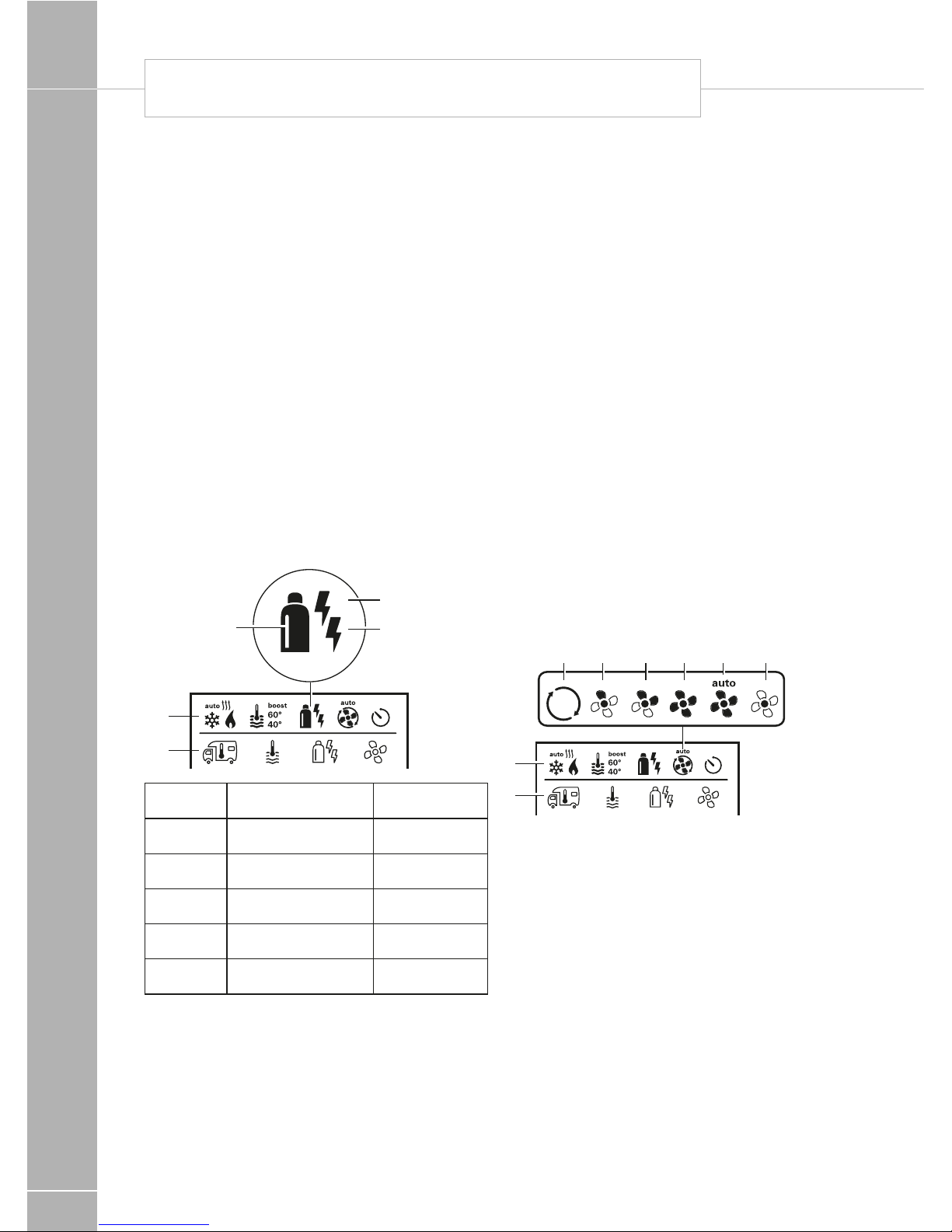
Butterfly outlets
Blown air
The air ducting outlets on some models are
of the butterfly type, and if fitted these may be
opened or closed by adjusting the butterfly
valves. Twisting the disc in its housing directs
the flow in the direction required. One outlet
on each leg of the air ducting layout must
be kept open at all times, and when high
specification (Combi 6) heating systems are
fitted, depending on the number of blown air
outlets in the layout, butterfly fittings may not
be present.
Under no circumstances should the air ducting
outlets be blocked.
Note: The next instructions detail the
operation of the Combi Control Panel
- for further details of the Truma Combi
appliance, please see the following section.
Truma Heating System
Control Panels
Depending on the specification of your
caravan, when the Combi heating is fitted,
either a CP25 Controller or CP Plus Controller
will be fitted.
Truma CP 25
Digital Timer Control
Operating instructions
Depending on the specification of your
caravan, the CP25 controller may be fitted
to control the operation of the Truma Combi
appliance.
Please be sure to read the instructions for
installation and use before attempting to
connect and use this device!
Symbols used
! Symbol indicates a possible hazard.
Comment including information and tips.
Safety instructions
! To protect you from electrical shocks,
injury or burns the following basic safety
principles must be observed when using
electrical devices. Please read and follow these
instructions before using the device.
Installation
Ensure that the devices are positioned safely
and cannot fall down or over. Always position
the cables to ensure they do not pose a
tripping hazard. Do not expose electrical
devices to rain. Do not operate electrical
devices in damp or wet environments. Do not
operate electrical devices close to flammable
liquids or gases. Position the devices so that
they are out of the reach of children.
Protection against an electrical shock
Only operate devices whose casings and
cables are undamaged . Ensure the cables are
installed safely. Do not pull on the cables.
TRUMA DIGITAL TIMER CONTROLS
FITTED EQUIPMENT
96
TRUMA CP 25 DIGITAL TIMER CONTROL
Use
Do not use electrical devices for purposes
other than those stated by the manufacturer.
Repairs
Do not repair or modify the device. Please
contact your dealer or the Truma Service (see
service manual or www.truma.com).
Accessories
Only use accessories and additional devices
that are supplied or recommended by the
manufacturer.
Intended use
The CP 25-UK is a digital operating / display
and control unit for the Combi Boiler.
The device is designed to be installed in
caravans and motorcaravans.
Initial operation or activation after a
power cut
After the operating voltage has been
connected , the unit will beep and the display
remains dark. To switch on, press the key 4
and the main screen will appear.
Function description
Note: More details regarding the operating
modes can be found in the operating
instructions of your Combi.
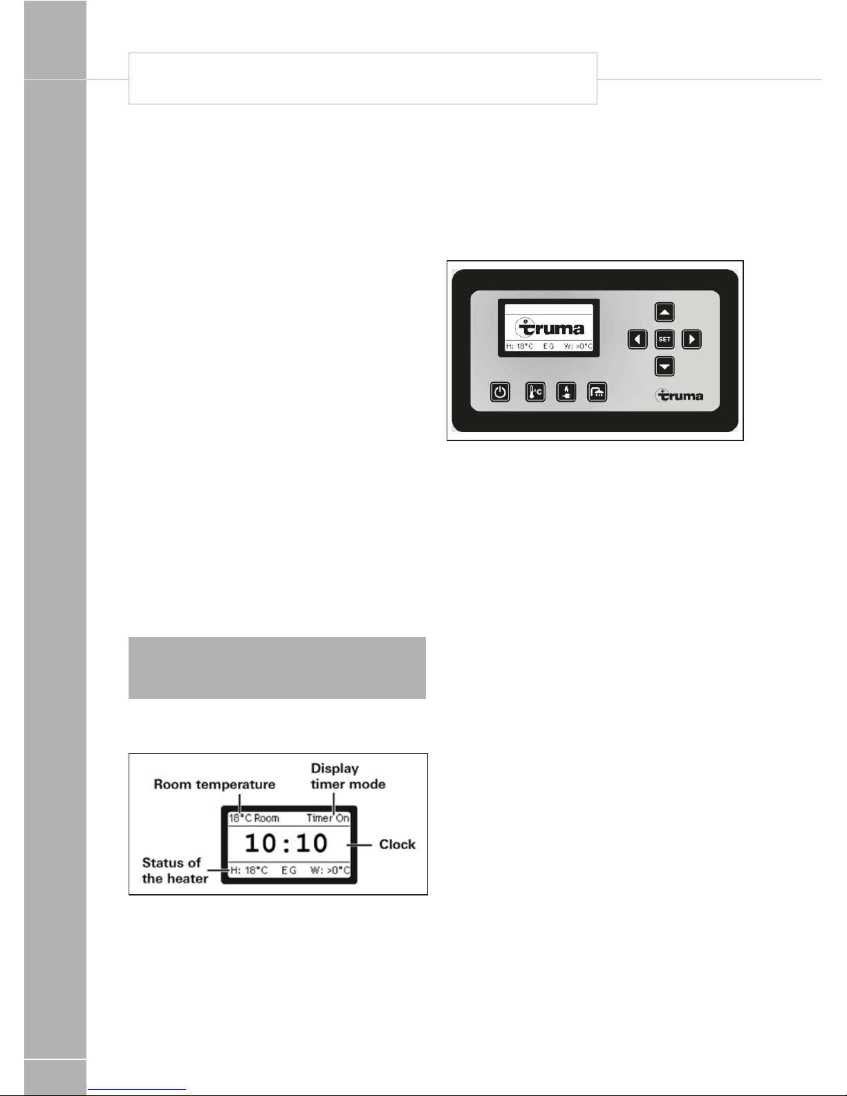
Main Screen
Room temperature: Display on when the
heater is active
Timer: Display on when the timer is active
Clock: Only if the clock has been set,
otherwise the Truma logo will appear
in the display
Status of the heater :
H: Set room temperature (e.g. 18°C)
EG: Energy selection (E = Electro, G = Gas)
W: Set water temperature
Selection Key upwards to select functions
or set values
Selection key downwards to select
functions or set values
Selection key backwards to select values
Selection key forwards to select values
On / Off
• Display and heater is switched on and /
or off
• The clock is shown when the time is set
• After an interruption in the operating
voltage, the display and the heater are
switched off. If the time is shown, this
needs to be set.
Green LED shines when the heater is on
Greed LED flashes when the heater is
after-running
Red LED shines when there is a malfunction
Manual mode
• In manual mode, the heater is controlled
via the 4 keys below the display.
• It is not necessary to set the time because
the Truma logo is shown in the display
instead of the time.

FITTED EQUIPMENT
97
Note: A pre-selection between summer
/ winter operation must be made via the
set-up.
Room Temperature
When the menu is selected the yellow LED
shines.
The current set room temperature is displayed
and can be changed.
Key increases the room temperature (max
30°C) by 1°C.
Key reduces the room temperature (min
5°C) by 1°C.
A change in the room temperature needs to be
confirmed with SET.
Energy selection
When the menu is selected the yellow LED
shines.
Depends on summer / winter operation
(see setup)
• Use key or to select the energy
source and confirm with SET.
• Bar shows current mode.
Summer operation
230 V - 4 A (electro mode 230 V, 900 W)
230 V - 8 A (electro mode 230 V, 1800 W)
Gas powered
Winter operation
230 V - 4 A (electro mode 230 V, 900 W)
230 V - 8 A (electro mode 230 V, 1800 W)
Gas powered
230 V - 4 A and gas (mixed operation gas and
electro mode 900 W)
230 V - 8 A and gas (mixed operation gas and
electro mode 1800 W)
Note: If electro or mixed operations are
selected and there is no 230 V power
supply, the heating will not function.
Water temperature
When the menu is selected the yellow LED
shines. During the heating-up phase, the set
water temperature flashes in the main screen.
• Use key or to select the water
temperature and confirm with SET.
• Bar shows current mode
Depends on summer / winter operation
(see setup)
Summer operation
Water 40°C
Water 60°C
Winter operation
Water > 0°C (heating without controlled water
temperature, heating has priority)
Water > 60°C
Timer mode
• The heater runs in timer mode as soon
as one or both timers have activated in
the setup.
• ‘Timer On’ appears in the main screen.
• The heater is only active in the set time
window (active timer)
• Only the energy selection can be changed
in the case of an active timer
• A change in the room or water
temperature will automatically switch the
control system into manual mode.
Set up
In the main screen display you can enter the
setup menu via the setup key.
The following settings can be made:
Back (return to main screen)
Timer 1 on / off (select SET on / off)
Timer 2 on / off (select SET on / off)
Summer / Winter (select SET summer /
winter)
FITTED EQUIPMENT
98
Set clock
Set timer 1
Back (Return to main screen)
Start (Set start time)
Stop (Set stop time)
Water (Set water temperature)
Temp (Set room temperature)
The timer settings can be made every day until
the timer is switched off. If the room or water
temperature is changed outside the timer
menu, the timer is automatically switched off.
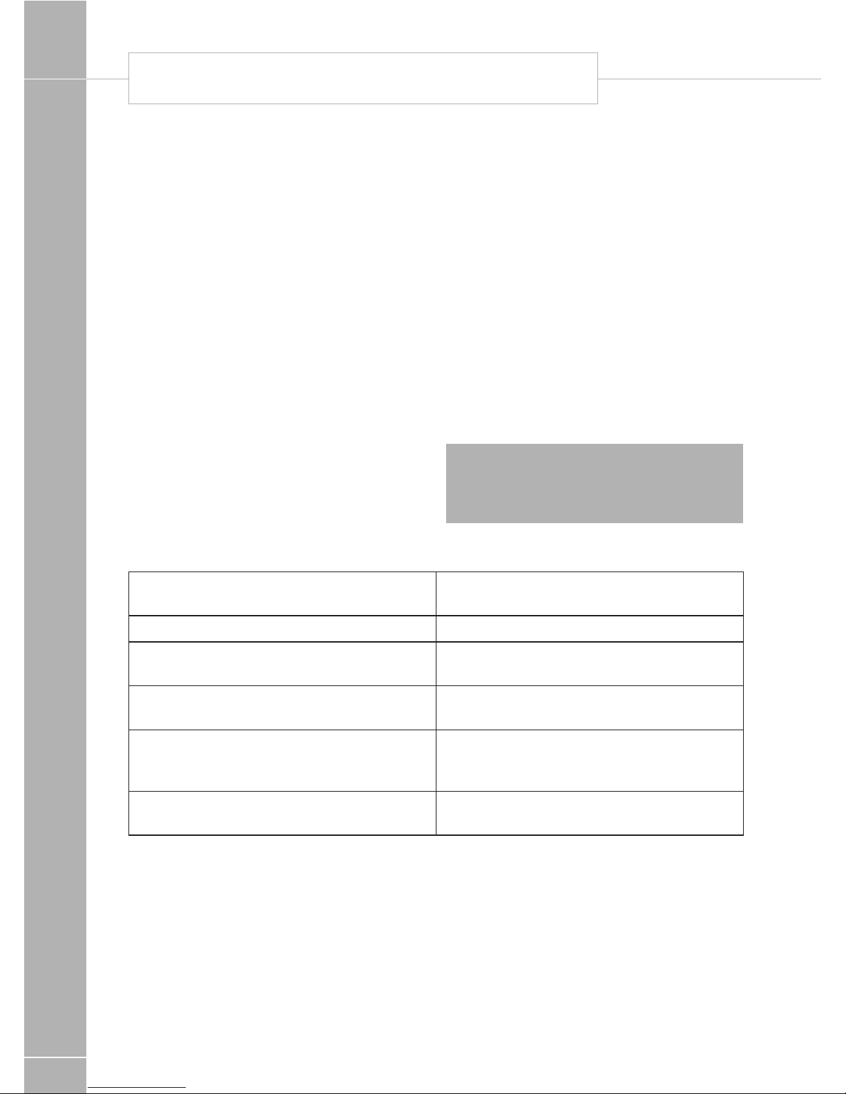
Trouble shooting list
Fault Rectification / Cause
Clock is not shown Set clock
Activated timer is not shown anymore Power supply was interrupted
Room temperature is not shown Heater not active
Device does not react anymore Interrupt power supply for 10 seconds
Heater / display does not react Check 12 V supply voltage
If these measures do not rectify the problem,
please contact the next Truma service point
(See Truma service book or www.truma.com)
Set timer 2
Back (Return to main screen)
Start (Set start time)
Stop (Set stop time)
Water (Set water temperature)
Temp (Set room temperature)
The timer setting can be made every day until
the timer is switched off. If the room or water
temperature is changed outside the timer
menu, the timer is automatically switched off.
Buzzer on / off (select SET on / off)
Backlight (brightness levels 0-9)
Note: If no action is taken, the display
switches back to the main screen after a few
seconds. The lighting switches off after a
short delay.
TRUMA CP 25 DIGITAL TIMER CONTROL

FITTED EQUIPMENT
99
Truma CP Plus
Digital Timer Control
Depending on the specification of your
caravan, the Truma CP-Plus controller may
be fitted to control the operation of the Truma
Combi appliance.
Safety instructions
• The device may only be operated if it is in
perfect working order.
• Arrange for malfunctions to be rectified
immediately. Only rectify malfunctions
yourself, if the remedy is outlined in the
troubleshooting information in these
Operating Instructions.
• Do not repair or modify the device!
• Only allow the manufacturer or its customer
service to repair a faulty device.
Note: If the power supply to the systems is
interrupted for longer than 20 minutes, the
time and date need to be entered again.
Important note
If the power supply to the systems is
interrupted for longer than 20 minutes, the
time and date need to be entered again.
Intended use
The control panel Truma CP plus serves to
control and monitor a Combi heater and /
or a Truma air conditioning unit. The device
is designed for installation in caravans and
motor-caravans.
For clarity only the instructions relevant to
combi heating are included in this guide.
Instructions relevant to air conditioning should
be requested if an appropriate air conditioner
is fitted.
FITTED EQUIPMENT
100
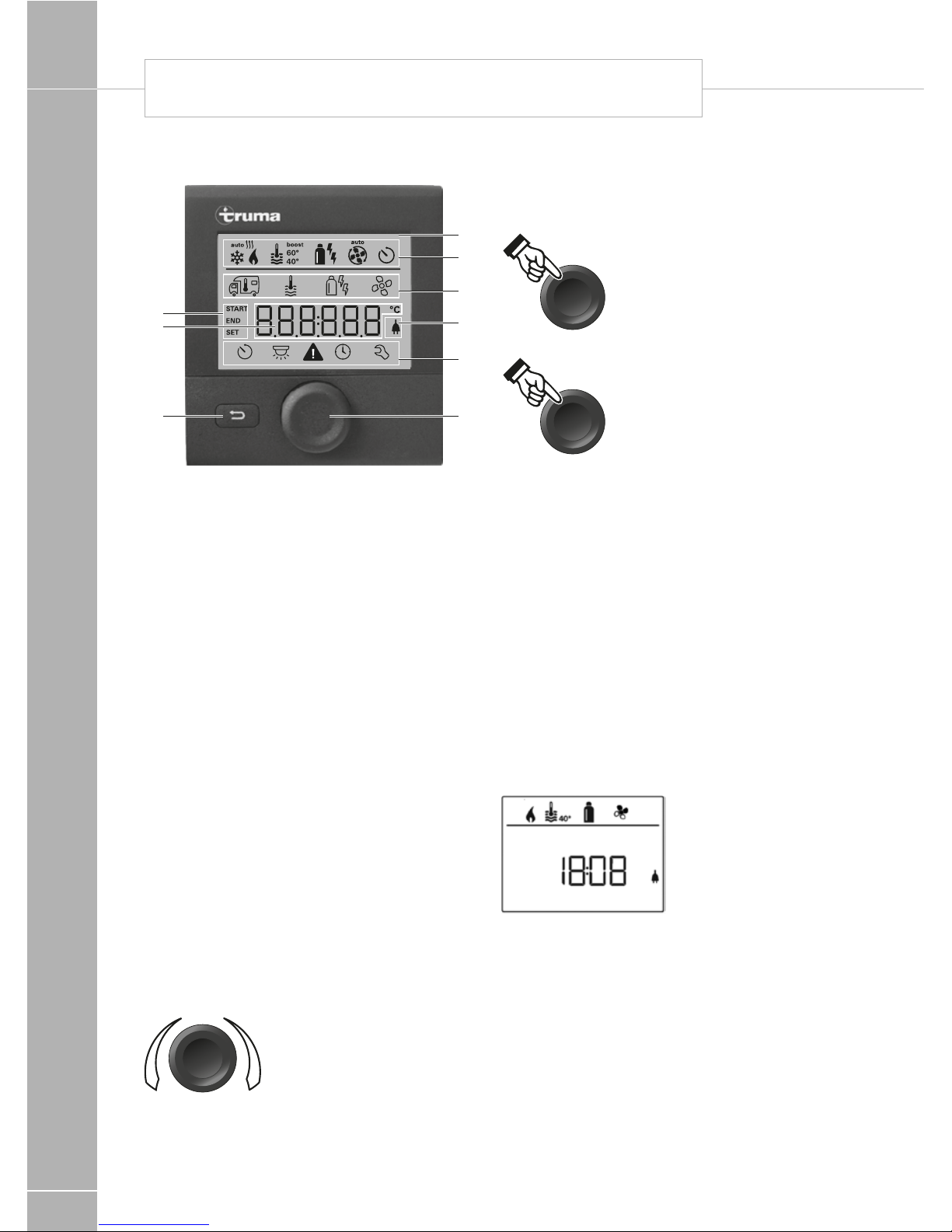
Display and control elements
2
3
5
4
8
6
7
9
1
1 - Display
2 - Status line
3 - Menu line (above)
4 - Menu line (below)
5 - Display of mains voltage 230 V
(shore power)
6 - Display timer
7 - Settings / values
8 - Control knob / push button
9 - Back button
The control knob / push button (8) is used to
select menus in the lines (3 + 4) and configure
the settings. These are shown via a display (1)
with a lighted background. Pressing the Back
button (9) takes the user back out of the menu
again.
Control knob / push button
The control knob / push button (8) is used to
select and change set values and parameters;
these can be saved by clicking the control
knob / push button. Selected menu items will
flash.
+
-
Turn to the right (+)
• Menu is paged from left
to right.
• Increase values.
Turn to the left (-)
• Menu is paged from right to left.
• Reduce values.
Clicking
• Accept (save) a selected
value.
• Select a menu item, change
to the setting level.
3 sec
Press (3 seconds)
• Main switch function
ON / OFF
Back button
Pressing the Back button (9) takes the user
back out of the menu again and discards the
settings. This means that the previous values
are retained.
Functions
The functions in the menu lines (3, 4) of the
control panel can be selected in any sequence.
The operating parameters are shown in the
status line (2) or the displays (5, 6).
Start / stand-by screen
After connecting the control panel to the
power supply, a start screen is shown after a
few seconds.
If no entry is made within a few minutes, the
standby screen is automatically shown again.
The display shows the time and current room
temperature alternately.
TRUMA CP PLUS DIGITAL TIMER CONTROL
FITTED EQUIPMENT
101
Switch on / return to setting level
• Press the control knob / push button for
longer than 3 seconds or the
• Back button.
The display shows the setting level. The first
symbol flashes.
Note: Previously set values / operating
parameters become active again after the
system is switched on.
Switch off
• Press the control knob / push button for
longer than 3 seconds.
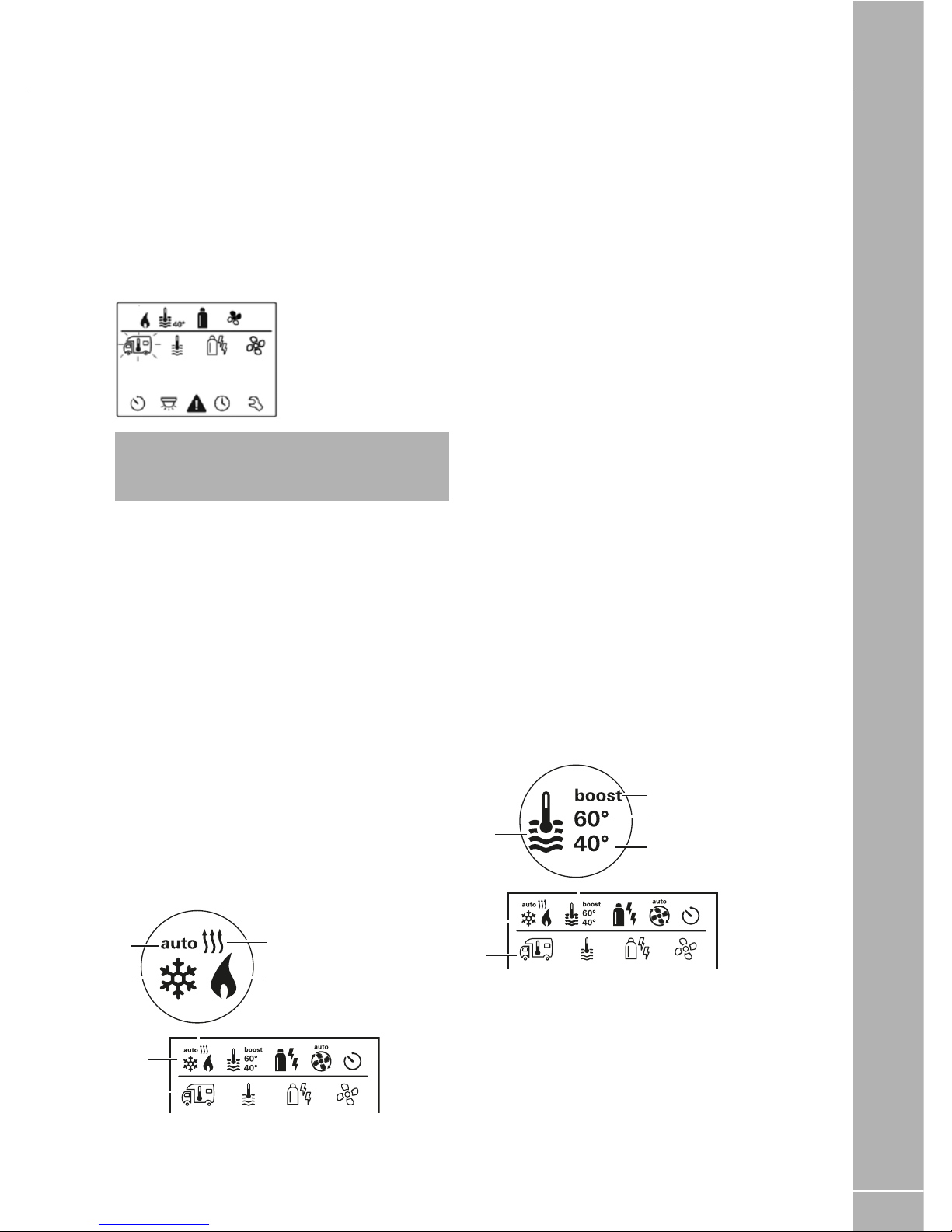
Change the room temperature
• Use the control knob / push button to select
the symbol in menu line (3).
• Click to change to the setting level.
• Depending on the connected device, use the
control knob / push button to select between
the heater or air conditioning unit.
• Use the control knob / push button to select
the required temperature.
• Click the control knob / push button to
confirm the value.
2
3
a
d
b
c
Heater
Settable temperature range 5 - 30 °C (1 °C
steps)
a = heater * – Heater is switched on.
Air conditioning unit (not normally fitted)
Settable temperature range 16 - 31 °C (1 °C
steps)
b = cool *
( Air conditioning unit is switched on)
c = auto
(Air conditioning unit is set to automatic)
d = hot
(Air conditioning unit is in heating mod.)
* This symbol will flash until the required room
temperature is reached.
Change the warm water level
• Use the control knob / push button to select
the symbol in menu line (3).
• Click to change to the setting level.
• Use the control knob / push button to select
the required level.
• Click the control knob / push button to
confirm the value.
2
3
a
b
c
d
a = Boiler *
(Warm water boiler is switched on)
b = 40°
(Warm water temperature 40 °C)
c = 60°
(Warm water temperature 60 °C)
FITTED EQUIPMENT
102
d = boost *
(Targeted, fast heating of the content of the
boiler [boiler priority]. The water temperature
is kept at the higher level [around 62 °C] – Not
Combi Diesel. Once the water temperature is
reached, the room is heated again.)
* This symbol will flash until the required water
temperature is reached.
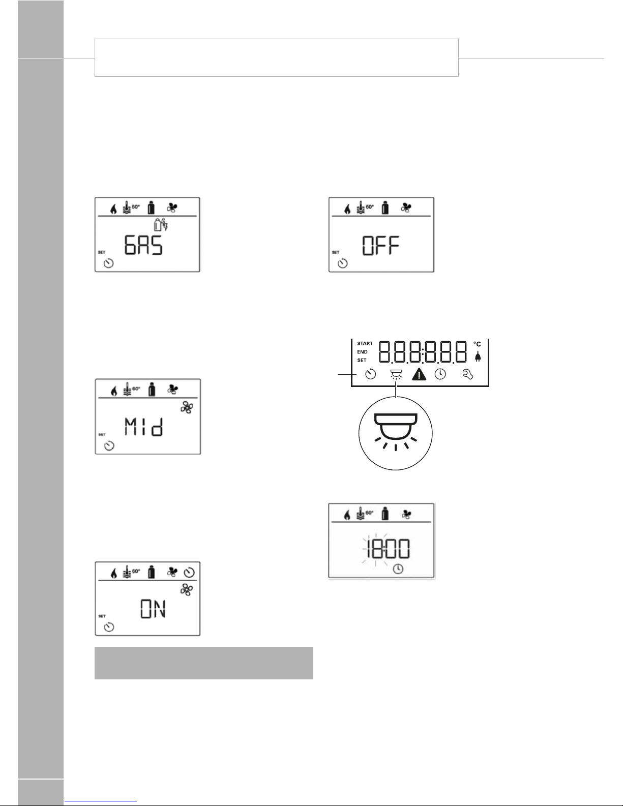
Select power type
• Use the control knob / push button to select
the symbol in menu line (3).
• Click to change to the setting level.
• Use the control knob / push button to select
the required power type.
• Click the control knob / push button to
confirm the value.
2
3
a
b
c
Symbol Operating mode Power type
a Gas Gas
b EL 1 Electro
b + c EL 2 Electro
a + b Mix 1* Gas + Electro
a + b + c Mix 2* Gas + Electro
* Mixed mode
Special aspects in the mixed mode
Interruption of the power supply 230 V
Combi Gas
The heater automatically switches to the gas
mode. As soon as the 230 V power supply is
reconnected, the heater automatically switches
back to the mixed mode.
Malfunction in the combustion process
(e.g. lack of fuel)
Combi Gas
The heater automatically switches to the
electro mode. If the heater should operate
in the mixed mode again, the cause of the
malfunction needs to be rectified. Switch the
heater off and on again on the control panel.
Select fan level
When the heater / air conditioning unit is
connected.
• Use the control knob / push button to select
the symbol in menu line (3).
• Click to change to the setting level.
• Use the control knob / push button to select
the required fan level.
• Click the control knob / push button to
confirm the value.
2
3
a b c d e f
TRUMA CP PLUS DIGITAL TIMER CONTROL

FITTED EQUIPMENT
103
Symbol Operating mode Description
– Off Fan is switched off
a Vent
Circulating air, if no device is in operation. 9 speed levels can
be selected.
b Eco Low fan level
c Mid High fan level (only Combi Gas)
d High
Fast heating of the room. Available, if the difference between
the selected and current room temperature is >10 °C.
Set timer
• Use the control knob / push button to select
the symbol in menu line (4).
• Click to change to the setting level.
Note: If the timer is activated (ON), the timer
in the menu is shown as deactivated (OFF).
Enter start time
• Use the control knob / push button to set the
hours, then the minutes.
Enter end time point
• Use the control knob / push button to set the
hours, then the minutes.
Note: If the start / end times are exceeded
when entered, the operating parameters are
only taken into consideration when the next
start / end times are reached. Until then, the
operating parameters set outside the timer
remain valid.
Set the room temperature
• Click to change to the setting level.
• Use the control knob / push button to select
the required room temperature.
• Click the control knob / push button to
confirm the value.
Set the warm water level
• Click to change to the setting level.
• Use the control knob / push button to select
the required warm water level.
• Click the control knob / push button to
confirm the value.
FITTED EQUIPMENT
104
Select power type
• Click to change to the setting level.
• Use the control knob / push button to select
the power type.
• Click the control knob / push button to
confirm the value.
Select fan level
• Click to change to the setting level.
• Use the control knob / push button to select
the required fan level.
• Click the control knob / push button to
confirm the value.
Activate the timer (ON)
• Click to change to the setting level.
• Use the control knob / push button to
activate the timer (ON)
• Click the control knob / push button to
confirm the value.
Note: The timer remains active, even for
several days, until it is deactivated (OFF).
Deactivate the timer (OFF)
• Click to change to the setting level.
• Use the control knob / push button to
deactivate the timer (OFF)
• Click the control knob / push button to
confirm the value.
Switch lighting on/off
Available if an air conditioning unit is connected
4
Set time
• The hour display flashes.
• Use the control knob / push button to set the
hours (24 h mode).
• After clicking the control knob / push button
again, the minute display will flash.
• Use the control knob / push button to set the
minutes.
• Click the control knob / push button to
confirm the value.
TRUMA CP PLUS DIGITAL TIMER CONTROL
FITTED EQUIPMENT
105
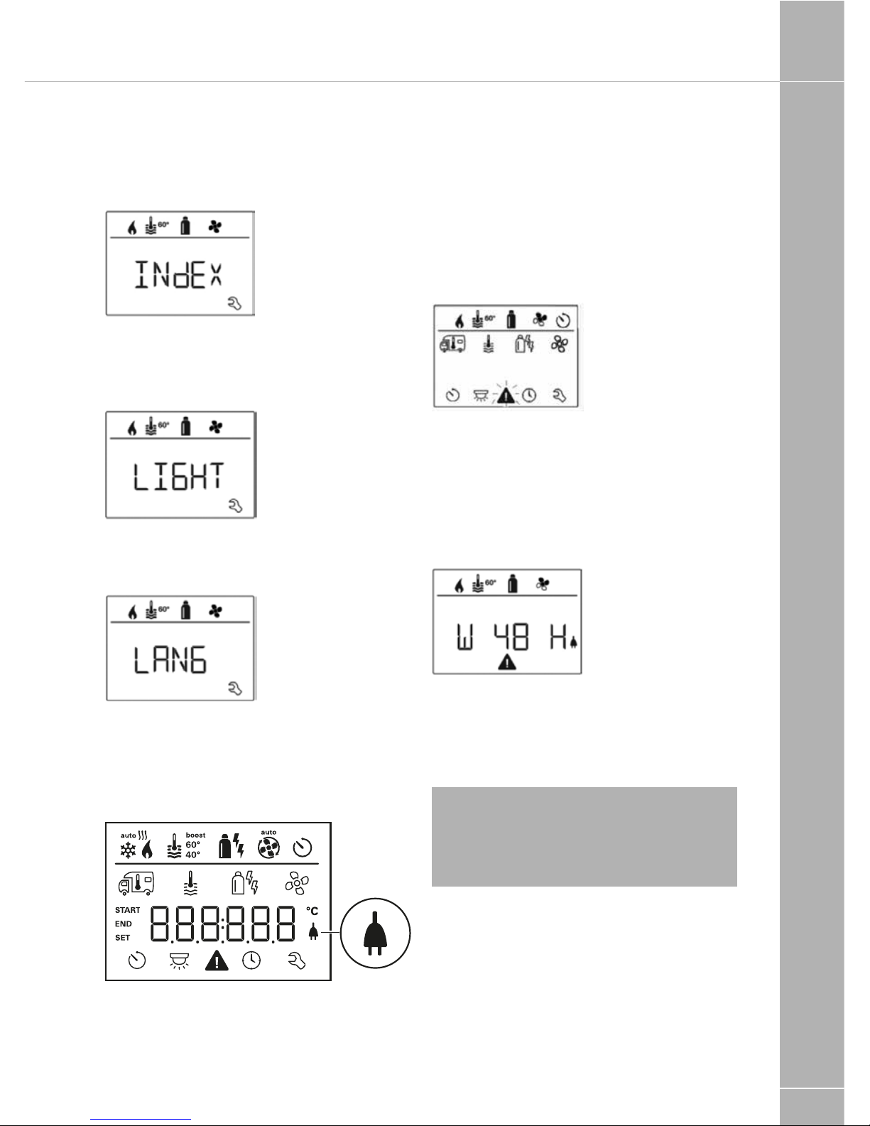
Service menu
Query the index status of a
connected device
Change the background lighting of the
control panel
There are 5 background lighting levels to
choose from.
Change language
Select the required language from those
available (e.g. English, German, French, Italian).
Display mains voltage 230 V
The symbol indicates that 230 V mains voltage
(shore power) is available.
Warning
In the event of a warning, a warning symbol
appears to indicate that an operating
parameter has reached an undefined status.
In this case, the affected device continues
to run. As soon as the operating parameter
returns to the set range, this symbol will turn
off automatically.
Read out the warning code
• Use the control knob / push button to select
the symbol.
• Click the control knob / push button. The
current warning code is shown. The cause of
the warning can be identified and rectified via
the error list.
Cause rectified / return to setting level
• Click the control knob / push button.
Cause not rectified / return to setting level
• Press the Back button
Note: In this case, the warning is not
acknowledged on the control panel and the
warning symbol remains. The control panel
remains in the warning status. Devices connected to the control panel can be operated.
FITTED EQUIPMENT
106
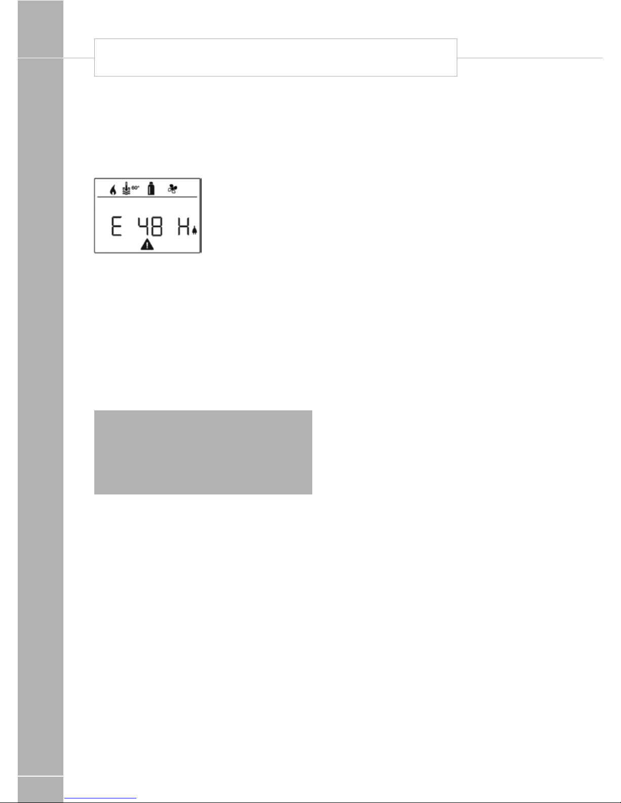
Malfunctions
In the case of a malfunction, the control
panel immediately jumps to the menu level
“malfunction” and shows the error code of the
malfunction:
Cause remedied / return to setting level
• Click the control knob / push button.
• The respective device is restarted.
If the cause is not remedied, the malfunction
will occur again and the control panel will jump
again to the menu level “malfunction”.
Cause not remedied / return to
setting level
• Press the Back button.
Note: In this case, the malfunction is not
acknowledged in the control panel and the
warning symbol remains on. The device
remains in the malfunction status. Other
devices connected to the control panel can
be operated.
Maintenance
This device is maintenance-free. Use a nonabrasive damp cloth to clean the front. If this
proves inadequate, use a neutral detergent.
Disposal
The device must be disposed of in compliance
with the administrative provisions of the
respective country in which it is used. The
national regulations and laws (in Germany
these are e.g. the End-of-Life Vehicle
Regulations) must be observed.
TRUMA CP PLUS DIGITAL TIMER CONTROL

FITTED EQUIPMENT
107
Troubleshooting instructions
(Combi Gas heater)
Error code Cause Remedy
#17 • Summer mode with empty water
container
• Warm air outlet blocked
• Circulated air intake blocked
• Switch device off and allow to cool.
Fill boiler with water
• Check each of the outlet openings
• Remove the blockage from the
circulated air intake
#18 • Gas pressure regulator frozen
• Too much butane in the gas
cylinder
• Use the regulator heating (EisEx)
• Use propane (Butane is unsuitable
for heating, especially at temperatures below 10
o
C
#21 • Room temperature sensor or
cable faulty
• Please contact the Truma Service
#24 • Potential under-voltage battery
voltage too low <10.4V
• Charge battery
#29 • Heating element for FrostControl
has a short circuit
• Disconnect the heating element
plug on the electronic control unit.
Replace heating element
#41 • Electronics are blocked • Please contact the Truma Service
#42 • Window above the cowl is open
(window switch)
• Close the window
#43 • Over-voltage > 16.4V • Check the battery voltage and volt-
age sources eg. the charger
#44 • Under-voltage battery voltage too
low < 10.0V
• Charge battery. Replace any
old batteries
#45 • No 230V operating voltage
• Faulty 230V fuse
• Overheating protection has
triggered
• Reconnect the operating
voltage 230V
• Replace the 230V fuse
• Reset the overheating protection.
Allow the heating to cool down,
remove the connection cover and
press the reset button
#112 • Gas cylinder or quick-acting valve
in the gas line closed
• Check the gas supply and open
the valves
#212 • Combustion air intake or exhaust
outlet closed
• Check the openings for soiling
(snow, ice, leaves etc) and remove
#255 • No connection between the heater
and the control panel
• Control panel cable faulty
• Please contact the Truma Service
If these steps do not rectify the malfunction,
please contact the Truma Service.
TRUMA COMBI BOILER FAULT FINDING

FITTED EQUIPMENT
108
Truma Combination Heating
System Function Description
The liquid gas heater Combi E is a warm-air
heater with integrated hot water boiler (10 liter
volume). The burner operates fan-supported,
which ensures trouble-free function even
when on the move. The unit also has heating
elements for electrical operation.
In winter operation the heater can be used to
heat the room and simultaneously warm water.
3 different options are available for operating
the unit.
– gas operation only Propane / Butane for
autonomous use
– electrical operation only 230 V for stationary
use on camp sites
– or gas and electrical operation – mixed
operation only possible in winter mode.
Winter operation (Space heating with
water heating)
In winter operation, the unit automatically
selects the required power setting according
to the temperature difference between the
temperature set on the control panel and the
current room temperature. When the boiler
is filled, the water is automatically heated as
well. The water temperature depends on the
selected operational mode and the heater
output. All 3 energy selection options can be
used for winter deployment.
With gas operation the unit automatically
selects the output level that is required.
Depending on the fuse protection at the
camping site, power of 900 W (3.9 A) or
1800 W (7.8 A) can be manually selected for
electrical operation.
If more output is required (e.g. heating up
or low outside temperatures) gas or mixed
operation should be selected so that enough
heating power is always available. With
mixed operation, 230 V electrical operation
is preferred if the power requirement is low
(e.g. for maintaining the room temperature).
The gas burner is not enabled until the power
requirement is higher, and is the first to switch
off during heat-up operations.
Summer operation (Water heating only)
Gas operation or 230 V electrical operation
is used for hot water preparation. The water
temperature can be set to 40 °C or 60 °C.
With gas operation the water is heated at
the lowest burner setting. Once the water
temperature is reached, the burner switches
off. Depending on the fuse protection at the
camping site, power of 900 W (3.9 A) or
1800 W (7.8 A) can be manually selected for
electrical operation. Mixed operation is not
possible. With this
setting the unit automatically selects electrical
operation. The gas burner is not enabled.
Repairs may only be carried out by
an expert
Guarantee claims, warranty claims and
acceptance of liability will be ruled out in the
event of the following:
– modifications to the unit
(including accessories),
– modifications to the exhaust duct and
the cowl,
– failure to use original Truma parts as
replacement parts and accessories,
– failure to follow the installation and operating
instructions.
It also becomes illegal to use the appliance,
and in some countries this even makes it illegal
to use the vehicle.
During the initial operation of a brand new
appliance (or after it has not been used for
some time), a slight amount of fumes and
smell may be noticed for a short while. It is a
good idea to heat the device up several times
in summer operation (60 °C) and to make sure
that the area is well ventilated. Heat-sensitive
objects such as spray cans
or flammable liquids may not be stored in
the same compartment where the heater is
installed because, under certain conditions,
this area may be subject to elevated
temperatures.
Important operating notes
The integrity and tight fit of the exhaust gas
TRUMA COMBI BOILER

FITTED EQUIPMENT
109
double duct must be checked regularly,
particularly at the end of long trips. Also check
the mounting of the appliance and the cowl.
Following a blow-back (misfire) always have
the exhaust gas system checked by an expert!
Always keep the cowl for the exhaust duct and
combustion air intake free of contamination
(slush, ice, leaves etc.). A number of hot air
outlets and the recirculated air intake openings
must be free so that the unit does not
overheat. The integrated temperature limiter
blocks the gas supply when the unit becomes
too hot.
Operating Instructions
Always observe the operating instructions and
“Important operating notes” prior to starting!
The vehicle owner is responsible for the correct
operation of the appliance. Before using for the
first time, it is essential to flush the entire water
supply system through with clean water. If
the heater is not being used, always drain the
water contents if there
is a risk of frost. There shall be no claims under
guarantee for damage caused by frost!
Room thermostat
To measure the room temperature, a room
temperature sensor is fitted to the furniture.
The exact location is determined by the layout
of the vehicle.
Taking into operation
Heating is possible without restrictions with
gas, electrical and mixed operation, with or
without water. Check to make sure the cowl is
unobstructed. Be sure to remove any covers
that may be present.
For operating on gas turn on gas cylinder and
open the shut off valve at the manifold. For
operating on electric operate the water heater
switch on the power supply unit. See page 71.
Filling the water heater
Switch on power for water pump (main or
pump switch) to prime the water system. Open
hot water taps in kitchen and bathroom, (set
preselecting mixing taps or single-lever fittings
to “hot”). Leave the fittings open for as long as
it takes for the boiler to displace the air and fill
up, and the water to flow without interruption.
If just the cold water system is being operated,
without using the water heater, the heater tank
also fills up with water. To avoid frost damage,
the boiler must be drained through the drain
valve, even if the boiler was not operated.
When connecting to a central water supply
(rural or city mains), a pressure reduction valve
must always be installed to prevent pressures
above 2.8 bar from developing in the water
heater.
Draining the water heater
Switch off power to water pump (main or
pump switch). Open hot water taps in kitchen
and bathroom. In order to check the water that
is flowing out, place an appropriate container
(capacity 10 litres) beneath the drain valve.
Open the drain valve which is situated next to
the boiler by lifting the yellow handle into the
vertical position.
Check whether all of the water in the boiler (10
itres) has been drained into the container via
the drain valve.
There shall be no claims under guarantee
for damage caused by frost!
Maintenance
Only original Truma parts may be used for
maintenance and repair work! Materials in the
device which come into contact with water
are suitable for use with drinking water (see
manufacturer‘s declaration: www.truma.com /
downloads / manufacturer‘s declaration).
Bio-film, deposits and limescale must be
removed using chemicals to protect the
unit from infestation by microorganisms.
Only chloride-free products must be used
in order to prevent damage to the unit. The
effectiveness of the use of chemicals to
combat microorganisms in the unit can be
increased by heating the water in the boiler to
70 °C at regular intervals. The unit must stay
switched on for at least 30 minutes and no
warm water may be removed. The residual
heat in the heat exchanger will heat the water
up to 70 °C.
FITTED EQUIPMENT
110
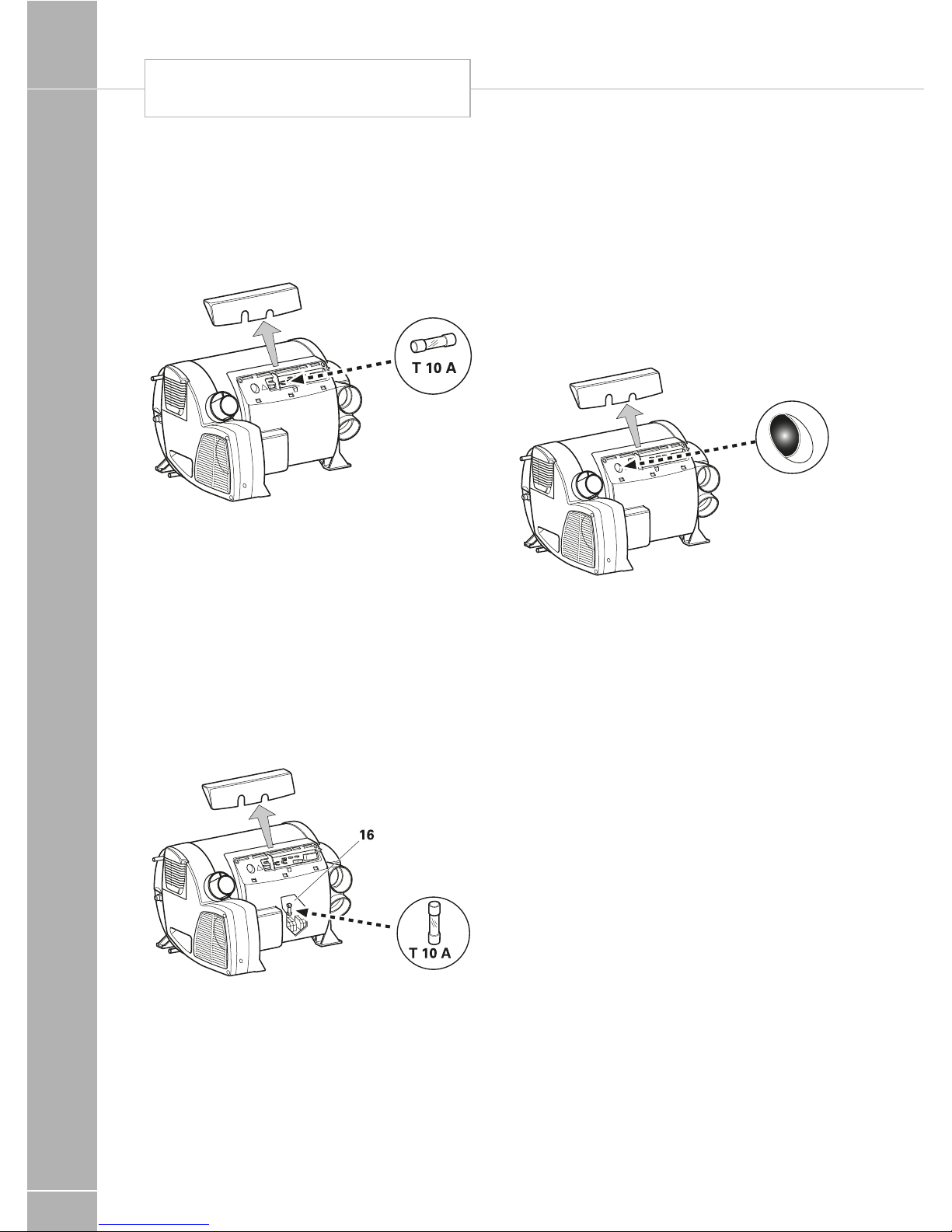
Fuses 12 V
The fuse is in the electronics beneath the
connection cover. Replace the unit’s fuse only
with an identical fuse.
Device fuse: 10 A – slow – (T 10 A)
Fuses 230 V
The fuse and the power supply lines must only
be replaced by an expert! The unit must be
disconnected from the mains (all poles) before
opening the electronic housing lid.
The fuse is in the power electronics (16)
beneath the electronic housing lid.
This fine fuse must always be replaced with a
fuse of the same type: 10 A, slow, interrupting
capacity “H”.
Overheating protection 230 V
The 230 V heating facility has a mechanical
overheating switch. If the 12 V power supply
is interrupted during operation or during the
after-run period, for example, the temperatures
within the unit could activate the overheating
protection. To reset the overheating protection,
allow heater to cool, remove connection cover
and press red reset button.
TRUMA COMBI BOILER

FITTED EQUIPMENT
111
Technical data
determined in accordance with EN 624 or
Truma test conditions
Device category
I
3 B/P
in accordance with EN 437
Type of gas
Liquid gas (propane/butane)
Operating pressure
30mbar (see type plate)
Water contents
10 litres
Heating up time from approx 15
O
C to 60OC
Boiler approx 20 minutes (measure according
to EN15033)
Heater + boiler approx 80 min
Water pressure
max 2.8 bar
Rated thermal output
(automatic output levels)
Gas operation
Combi 4 E: 2000 W / 4000 W
Combi 6 E: 2000 W / 4000 W / 6000W
Electrical operation
Combi 4 E / Combi 6 E: 900 W / 1800 W
Mixed operation (gas and electrical)
Combi 4 E: max. 3800 W
Combi 6 E: max. 5800 W
Gas consumption
Combi 4 E: 160-320 g/h
Combi 6 E: 160-480 g/h
Readiness-heat power requirement Combi 4 E
/ Combi 6 E:
Gas operation 5.2 g/h
Air delivery volume
(free-blowing without hot-air pipe)
Combi 4 E:
with 3 hot-air outlets max. 249 m3/h
with 4 hot-air outlets max. 287 m3/h
Combi 6 E:
with 4 hot-air outlets max. 287 m3/h
Current input at 12 V
Heater +boiler
Combi 4 E: Short-term max. 5.6 A
(average power consumption 1.1 A)
Combi 6 E: Short-term max. 5.6 A
(average power consumption 1.3 A)
Heating up of boiler: 0.4 A
Stand-by: 0.001 A
Heating element FrostControl (optional):
maximum 0.4 A
FITTED EQUIPMENT
112
Alde Compact 3010
Challenger and Eccles SE, Conqueror,
Elite and Cameo based models
Please read these instructions carefully
before using the boiler.
These instructions are approved for The Alde
Compact 3010 boiler fitted in caravans, motor
caravans and buildings in accordance with CE
no. EMC e5 02 0138, 845 BP-0003.
Installation and repairs may only be carried out
by a professional. National regulations must be
adhered to.
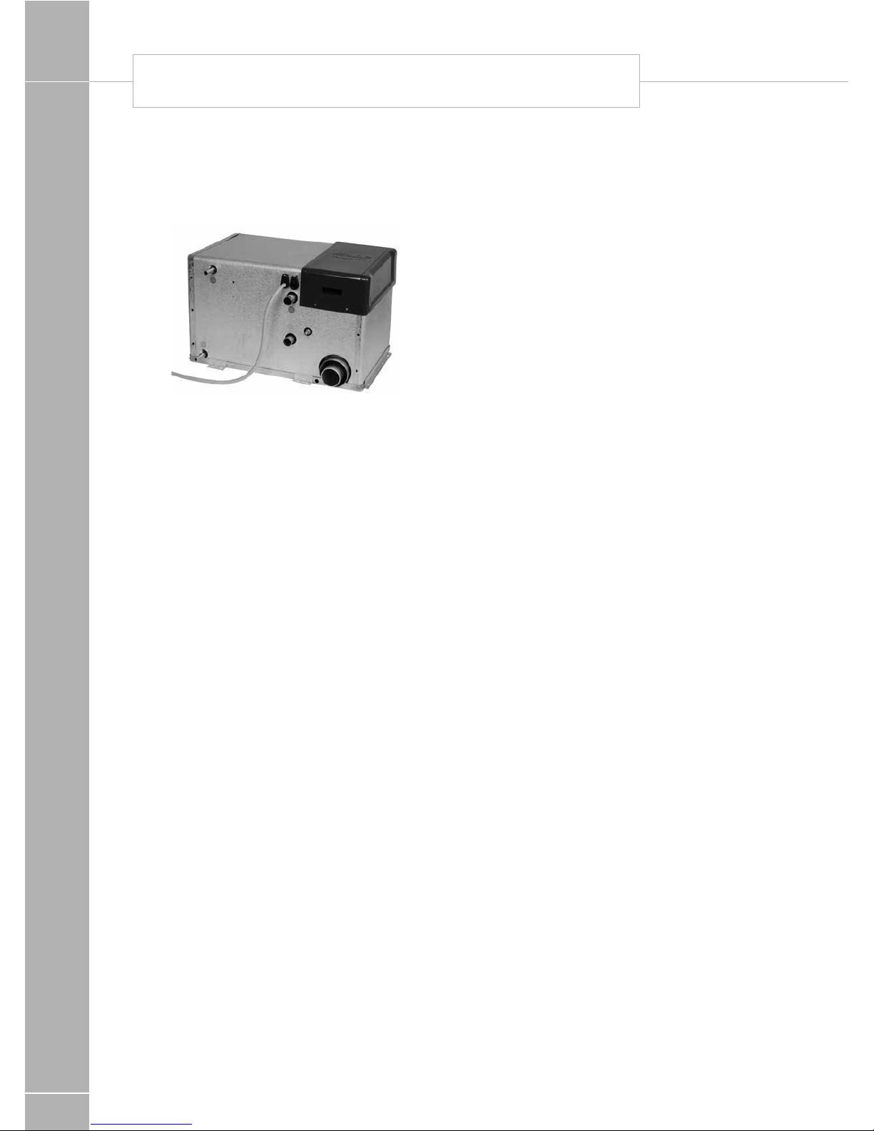
Boiler design
The boiler consists of three eccentrically- fitted
cylinders (heat exchanger, water jacket for the
heating system and, outermost, water jacket
for hot water). The two outer pipes, and their
ends and connections, are made of stainless
steel, while the heat exchanger is made of
aluminium.
The heat exchanger is divided into two semicircles. The burner is located in the upper
half, being the combustion chamber, and
the combustion gases are expelled through
the lower half. The burner unit is fitted on the
end of the heat exchanger. It consists of a
combustion fan, burner, solenoid valve and
intake/exhaust connections. Two heating
cartridges are fitted to the water jacket of the
heating system. Maximum output is 2 or 3 kW,
depending on model.
Description of functions
Using LPG
When LPG operation is selected on the control
panel, the combustion fan starts. When the
fan speed is correct, it signals the circuit
board that the boiler can be lit. The circuit
board sends ignition sparks to the spark plug
at the same time as it sends electricity to the
solenoid valve, which opens to allow gas in.
The burner ignites, and a sensor transmits a
signal back to the circuit board that the boiler
is lit, and the ignition spark stops. The burner
keeps burning until the boiler thermostat or the
room thermostat reaches the set temperature
reading.
Should the boiler go out for any reason, the
sensor is activated and a new attempt is made
to start the boiler (in about 10 seconds).
ALDE HEATING OPERATING INSTRUCTIONS

FITTED EQUIPMENT
113
Using the heating cartridge
Electrical operation is selected on the control
panel, the 12-volt relays on the circuit board
trip, allowing the 230 volt supply to reach the
electrical elements.
The heating cartridge is controlled in the same
way as the gas boiler.
Warm water
When only warm water is required, for example
during the summer, no settings need to be
made, the boiler will look after this function
automatically.
The pump will only start when the temperature
in the vehicle is lower than the set temperature
(see item 4, Control Panel). If the vehicle
temperature is higher, the pump will not start.
Important information
• The boiler must not be started if there is no
glycol in the system.
• The LPG boiler and heating cartridge may be
operated in parallel.
• The heating system may be heated up
without the warm water heater being filled
with fresh water.
• Always switch off the main isolator for the
boiler when the vehicle is not being used.
• Always drain the warm water heater of fresh
water if there is a risk of frost.
• The LPG boiler must not be operated when
refuelling the vehicle.
• When washing the vehicle, take care not to
get water in the venting.
! WARNING: Care should be taken
to ensure adequate ventilation of the flue
at all times. Its is inadvisable to inhale
exhaust fumes.
The Domestic hot water heater
The boiler is fitted with a built-in warm water
heater with a volume of approx. 8.5-litres fresh
water. The warm water heater can produce
around 12 litres of 40°C water per half-hour
(at a cold water temperature of 10°C). If the
heating cartridges are used instead of gas
for heating the boiler, the capacity is slightly
reduced. Always rinse out the heater before
it is used, particularly if it has not been in
operation for some time.
Note: The hot water is not intended for
drinking or cooking.
When the heater is in continuous use, it should
be emptied approx. once a month, to ensure
that a new air cushion is formed in the heater.
The air cushion is essential for absorbing
pressure surges in the heater.
Note: The warm water heater should
always be drained of fresh water when there
is a risk of frost and when the caravan is not
in use.
The warranty does not cover frost damage.
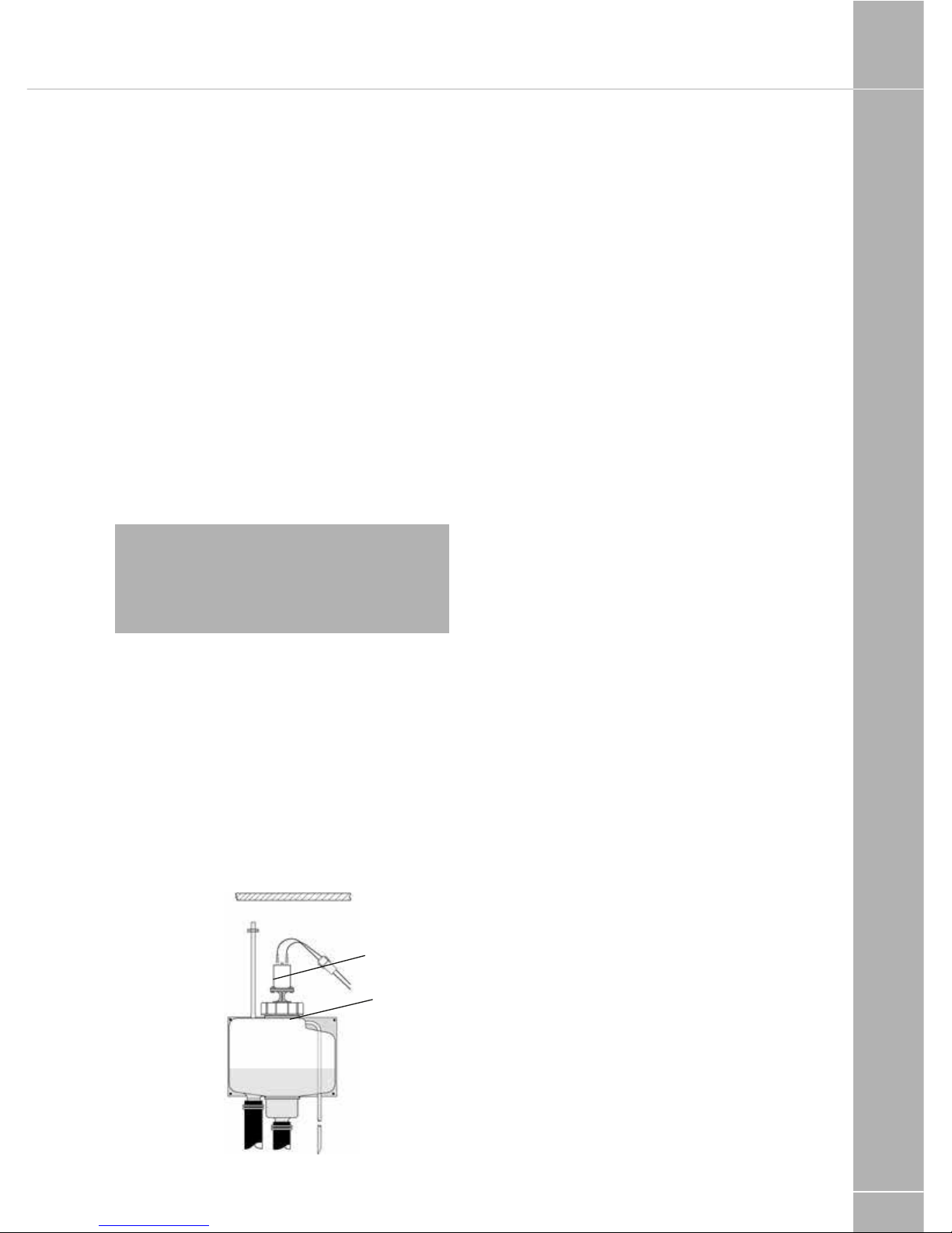
Draining the heater using the combined
safety/drain valve:
1. Switch off the freshwater pump
2. Open all water taps.
3. Then open the safety/drain valve by raising
the yellow lever (M) to a vertical position.
4. The heater will now drain directly below
the vehicle through the safety/drain valve
hose. Check that all the water is emptied out
(about 7-10 litres). Leave the valve in the open
position until the next time the heater is used.
Note: Check that the automatic check valve
(N) is open and is allowing air to enter the
heater when it is being drained, and that the
hose (O) is not blocked.

FITTED EQUIPMENT
114
Closed Open
M
N
The heating cartridges
All Compact 3010s are fitted with two 230V
heating cartridges with a maximum output
of either 2100 or 3150W. Select the heating
cartridge output on the control panel.
Always check that the input supply of the
vehicle has the correct amperage in relation to
the selected output.
Note these ratings are for the boiler only.
1050W requires a 6 amp fuse/supply.
2100W requires a 10 amp fuse/supply.
3150W requires a 16 amp fuse/supply.
The circulation pump
A circulation pump is required to circulate the
heated glycol fluid. A 12V circulation pump is
fitted in the expansion tank.
An optional 230V circulation pump can be
fitted on the boiler. Selection of circulation
pump is made with a switch on the control
panel. The room thermostat on the control
panel controls the circulation pump, i.e.
switches it on or off according to the amount
of heat required.
System temperature
The boiler is set to a system temperature of
80°C, i.e. the temperature of the glycol fluid as
it circulates in the heating system.
Air circulation
In order to achieve the best possible result
from the principle of convected heat, it is
important to allow air to circulate freely under
bunks, and behind backrests and wallmounted cabinets.
If the vehicle has a fitted carpet, ensure that
the carpet does not obstruct the air supply to
the radiators.
It is just as important that cushions or
blankets do not interrupt the flow of air behind
backrests and wall cabinets.
Note: During the first weeks of ownership
customers may notice a drop in the glycol
level and/or blocked radiators. This is normal
as the system settles.
Maintaining the heating system
Winter camping
While camping during the winter, ensure that
the flue is kept clear of snow and ice, since the
inlet air to the LPG boiler enters through the
flue. Do not start the LPG boiler until the flue
is completely free of snow. A flue extension
(part no. 3000 320) for fitting on the roof is
recommended for winter camping.
Air stream
Convectors
The heating system
Regularly check the heating system’s fluid level
in the expansion tank. The level should be
about 1cm above the minimum indicator in a
cold tank. The heating system should be filled
with a mixture of water and glycol.
For preference, use high quality ready mixed
glycol (with inhibitor) intended for use in
aluminium heating systems.
If using concentrated glycol, the mixture
should consist of 50% water and 50% glycol.
If the heating system will be exposed to
temperatures below -25°C, the glycol content
must be increased, but not to more than
50%. Any vessels used for the liquid must be
spotlessly clean, and the pipes in the heating
system must be free of contamination. This will
prevent the growth of bacteria in the system.
ALDE HEATING OPERATING INSTRUCTIONS
FITTED EQUIPMENT
115
The glycol mixture should be changed every
second year, since its ability to protect against
corrosion, for example, will deteriorate. The
glycol content should be checked before
topping up with new liquid. This will ensure
that the concentration of glycol in the mixture
is not too high.
If the fluid level in the expansion tank falls for
reasons other than evaporation, please check
all joints, drain cocks and bleeder screws to
ensure that they are not leaking. If the glycolwater mixture leaks out, rinse with water and
wipe up.
Never allow the heating system to stand empty
of glycol.
Filling the system with glycol fluid
Note: Any vessels used to carry the fluid
must be spotlessly clean and the pipes in
the system must be free of contamination.
This will prevent the growth of bacteria in the
system.
The system is filled through the expansion
tank, either manually or using the Alde filling
pump which both tops up and bleeds the
system. For manual filling, unfasten the
circulation pump nut (R) and lift the pump (S)
out of the tank. Slowly pour the glycol mixture
into the tank. Bleed the system.
Top up with more liquid if the level has fallen
after bleeding. Bleed a newly filled system
regularly during the first days the heating
system is in operation.
- MAX
- MIN
R
S
Types of glycol
Various types of antifreeze (as used in car
radiators) are available from service stations,
car accessory shops and on line retailers and
these types of antifreeze can be used to top
up or replace the heating system fluid in the
Alde heating system.
Frost and corrosion damage are not covered
under warranty, so it is important that the
type purchased contains corrosion inhibitors
suitable for use with aluminium systems.
Always check the label, ask the retailer for
advice, or check with your supplying dealer
if unsure. Please note the corrosion inhibitor
will have a limited life, and after it expires, the
system will have no corrosion protection.
The fluid will usually be named as Ethylene
glycol, but may also be described as
monoethylene glycol, MEG, ethanediol, or
G12++. There is no industry standard for
the colour of the antifreeze, but as a general
guideline it indicates the type of corrosion
inhibitor:
Blue, Green - Silicate inhibitor, usually offering
2-year corrosion protection
Red, Orange - OAT inhibitor, usually offering
5-year corrosion protection
Purple, Magenta - G12++ Silicated OAT
inhibitor, usually offering 5 year corrosion
protection
It is important that antifreeze containing Silicate
inhibitor (Blue or Green) is not mixed with
antifreeze containing OAT inhibitor (Red or
Orange). To guarantee compatibility, there are
two options:
1. Match the colour, taking care to also check
the label on the antifreeze bottle, i.e. if the
system is filled with blue silicate-containing
antifreeze, top up with blue silicatecontaining antifreeze.
2. Use G12++ antifreeze which is compatible
with any of the other types of inhibitor
described.

FITTED EQUIPMENT
116
Bleeding the system
Depending on how the pipes have been fitted,
air pockets may form when the system is filled
with glycol fluid.
A sign that there is air trapped in the system
is that the heat released into the pipes only
extends a metre or so from the boiler even
though the circulation pump is operating.
In newly-filled systems, small air bubbles
can form in the expansion tank, creating a
murmuring sound. If the circulation pump is
stopped for a few seconds, the bubbles will
disappear.
Bleeding:
If a bleeder screw is fitted to the outgoing pipe,
open this bleeder screw and leave it open until
it starts to discharge water.
If the boiler is fitted with an automatic bleeder,
there is no need to bleed it manually. Start the
LPG boiler. The circulation pump should be
switched off.
Open the remaining bleeder screws in the
system (please refer to the instruction manual
of the vehicle for their locations). Leave
the bleeder screws open until they start
discharging fluid, and then close them. Start
the circulation pump and let it run for a while.
Check that the pipes and radiators around the
vehicle are heating up.
If there are still issues, try the following:
Single-axle caravan:
Stop the circulation pump. Lower the front
of the caravan as far as possible. Leave it in
this position for a few minutes to allow the
air to travel upwards in the system. Open the
bleeder screw at the highest point. Leave it
open until it discharges glycol fluid. Raise the
front of the caravan as far as possible and
repeat the procedure in this position.
Then position the caravan horizontally and
start the circulation pump. Check that the
pipes and radiators around the vehicle are
heating up.
Twin-axle caravan:
The easiest way to bleed the heating system is
to place the vehicle on a sloping surface or to
raise one end of the vehicle using a jack. Bleed
the system as described above.
Fault finding
The boiler does not start
1. No LPG? Incorrect type for conditions?
2. Is the main tap fully open?
3. If the boiler has not been operated for
some time, or if the gas cylinder has been
changed, it may take longer than normal to
light the boiler.
4. Check that the boiler is connected to the
electricity supply (> 11V).
5. Check that the fuse (T) for the boiler
is intact.
6. Check whether the electric connections on
the boiler are securely in position.
If none of the above helps, contact a
service workshop.
The heating cartridge is not working
1. Check that there is an electricity supply
(230V ~) to the heating cartridge.
2. Check that the relays fitted to the boiler
come on (a slight click can be heard from
the relays when the heating cartridge is
switched on at the control panel).
If none of the above helps, contact a
service workshop.
ALDE HEATING OPERATING INSTRUCTIONS
FITTED EQUIPMENT
117
Operating instructions control
panel 3010 613
Please read these instructions carefully before
using the boiler. For Operating and Installation
Instructions of boiler, please see separate
instruction. These instructions are for the Alde
Compact 3010 boiler fitted in vehicles, boats
and buildings in accordance with CE no. 0845
BP0003, installation in vehicles e500 00005
and EMC e5 03 261.Installation and repairs
may only be carried out by a professional.
National regulations must be adhered to.
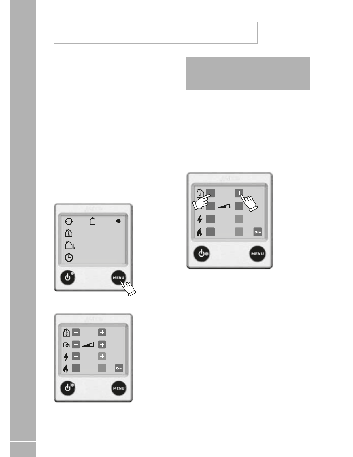
1. Starting the boiler
1. The control panel and the boiler are
switched off.
2. To start the boiler, press the On/Off button
and the start-up display is displayed. The
boiler starts with the last selected setting.
A green LED comes on beside the On-/Off
button when the panel/boiler is on.
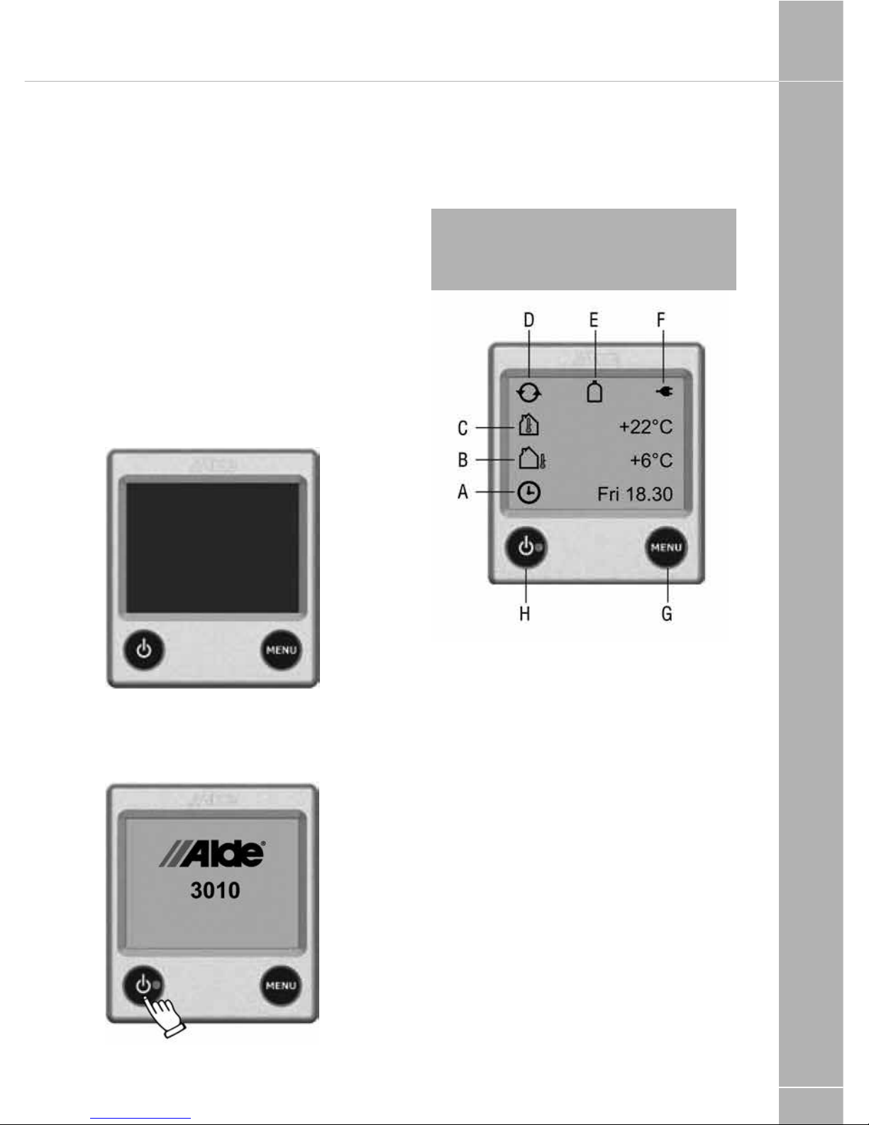
2. The control panel in standby mode
Note: if “Standby Brightness” is set to Off,
the display goes out when it enters standby
mode, but lights up if you press the screen.
See settings under 9.12.
A. Clock
The clock shows day and time. Theclock is set
under section 9 point 2.
B. Outdoor temperature
The outdoor temperature is displayed
only if an outdoor temperature sensor is fitted.
C. Indoor temperature
The indoor temperature is displayed
automatically.
D. Circulation pump
This symbol is displayed when circulation of
the central heating is called for.
E. LPG bottle full/empty
This symbol is displayed when the sensor on
the cylinder changeover is connected and
activated in accordance with section 9 point 8.
F. 230 volts
This symbol is displayed when 230V is
connected to the boiler.
G. MENU button
Button for setting menu.
FITTED EQUIPMENT
118
H. On/Off button
Shut down / turn on the boiler
3. From standby mode to setting menu
When on standby, the indoor temperature is
displayed, and the outdoor temperature is
displayed if an outdoor temperature sensor
has been connected. The background lights
up when you press the screen or the MENU
button. Start the setting menu by pressing
the MENU button. The background lights up
and those functions which can be set are
displayed. The settings are automatically saved
after 10 seconds. The control panel reverts to
standby automatically after 30 seconds if no
buttons are pressed (or if the MENU button in
the setting menu is pressed).
1. The control panel in standby.
+22°C
+6°C
Fri 18.30
2. The control panel in setting menu.
+22°C
ON
2 kW
OnOf
f
Note: if “Standby Brightness” is set to Off,
the display goes out when it enters standby
mode, but lights up if you press the screen.
See settings under 9.12.
4. Set the required temperature
The temperature can be set from +5°C to
+30°C in steps of 0.5°C. Warm water is
always available (50°C) when the boiler is on
and running on LPG and/or electricity. During
summer, when only warm water is required,
adjust the temperature setting to well below
the surrounding temperature so that central
heating circulation is not called for.
+22°C
ON
2 kW
OnOf
f
1. The temperature displayed is the
temperature which is set at present (in this
case 22.0°C).
2. Raise the temperature by pressing the +
button. Lower the temperature by pressing
the – button.
3. The settings are ready and the central
heating will circulate at the set temperature.
5. Hot water boost
If you need more warm water, you can raise
the water temperature temporarily from 50°C
to 65°C. After 30 minutes, the boiler reverts
to normal operation. While hot water boost is
activated, the circulation pump is stopped.
ALDE HEATING OPERATING INSTRUCTIONS

FITTED EQUIPMENT
119
+22°C
ON
2 kW
OnOf
f
1. Increase the quantity of warm water by
pressing the + button. When activated the
plus symbol changes colour to green.
2. The settings are ready.
If you wish to revert to the basic warm water
settings before 30 minutes have expired.
+22°C
ON
2 kW
OnOf
f
1. Reset the warm water by pressing
the – button.
2. The settings are ready.
6. Heating with electricity
Do as follows to active heating with electricity.
The greater the power, the better the heating
performance. In choosing between electricity
and gas, electricity is given priority.
+22°C
ON
2 kW
OnOf
f
1. Start and step between the various power
steps (Off, 1kW, 2kW or 3kW) with the
+ button or – button. The set value is
displayed on the screen. When activated
the plus symbol changes colour to green.
(Certain boilers are equipped with max 2
kW, selecting 3kW is not possible in these
cases.)
2. The settings are ready and the boiler is
working at set temperature.
3. To switch off the electrical operation, step
with the – button to Off.
7. Heating with gas
Do as follows to activate heating with gas. If
both electricity and gas are selected, electricity
is given priority.
+22°C
ON
2 kW
OnOf
f
1. Start the gas operation by pressing On. The
On symbol is activated and changes colour
to green.
FITTED EQUIPMENT
120
2. The settings are ready and the boiler is
working at set temperature.
3. In order to switch off gas operation,
press Off.
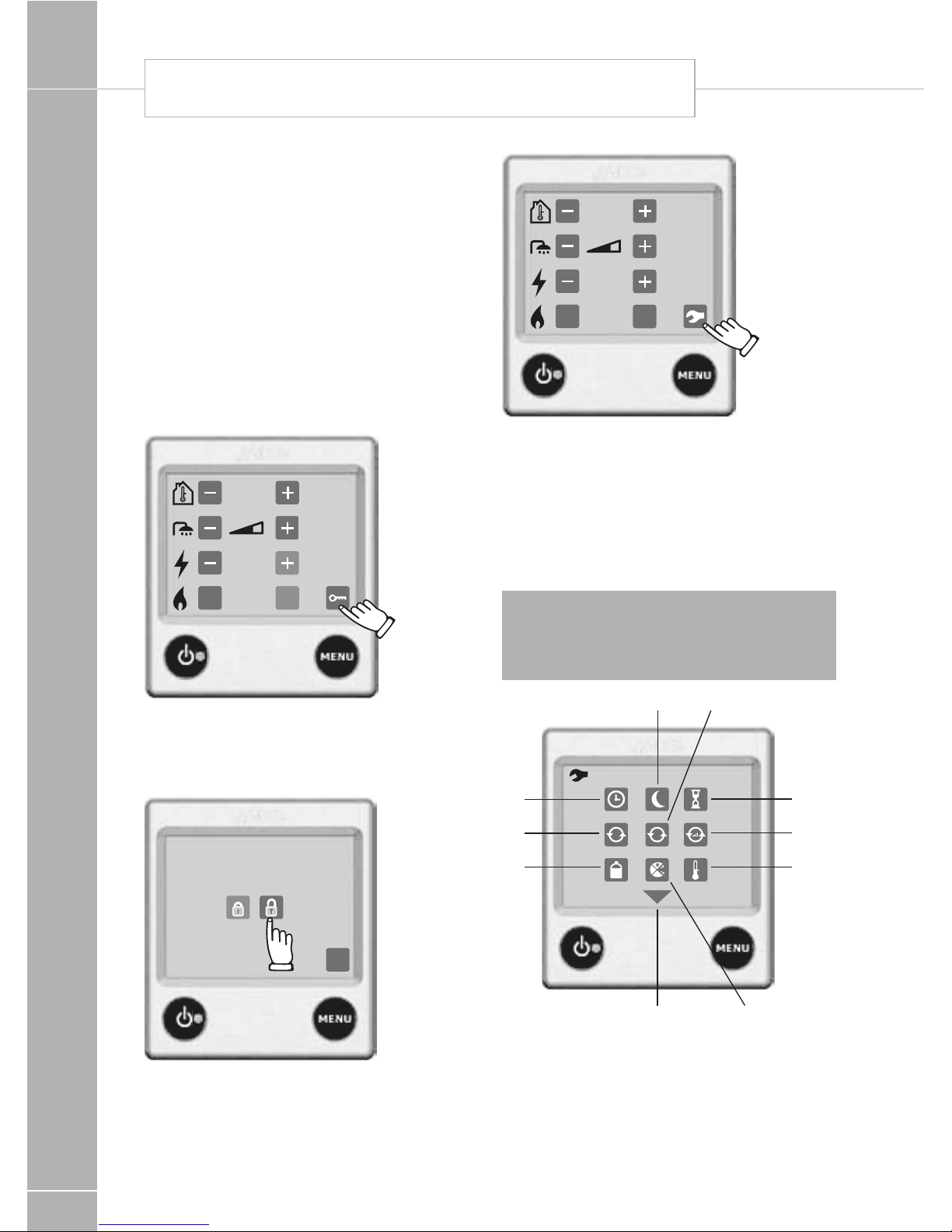
8. Unlocking the tool menu
It is possible to go from the setting menu to
the tool menu. Under the tool menu you can
access the other functions of the control panel,
described in section 9.
1. The control panel in setting menu.
Press the unlock symbol.
+22°C
ON
2 kW
OnOf
f
2. The control panel in unlocking menu. Press
on open padlock, then OK or MENU to
unlock the tools menu. When activated the
symbol changes colour to green.
OK
3. The control panel in setting menu with
unlocked tool menu. In order to get to the
tool menu, press the symbol.
+22°C
ON
2 kW
OnOf
f
9. The tool menu - functions
When you are in the tool menu (see section 8),
you can use the tools described below. Step
between the various tool fields by pressing the
up or down arrow symbols. You can always
leave the tool menu with the MENU button.
Note: Functions marked with * indicate
that the symbol for the function is displayed
on the control panel even if the accessory is
not installed!
5
A
7
4
5
2
8
1
9
36
10
ALDE HEATING OPERATING INSTRUCTIONS

FITTED EQUIPMENT
121
Ext
Lan
Amp
11
14 16
15
13
12
1. Arrow symbols
Step between the various tool fields
by pressing the up or down arrow
symbols. You can always leave the tool
menu with the MENU button.
2. Clock
The clock must be set if automatic
nighttime mode or automatic start is to
be used. If 12V voltage is lost, the clock
will be reset and correct time will no
longer be displayed. This is prevented
with an optional AA battery backup.
3. Automatic night-time mode
This function is used when you want
to programme the central heating to
automatically lower the temperature
at night and raise the temperature in
the morning.
4. Starting the boiler automatically
This function is used to start the boiler
automatically at a later point of time.
With automatic start, the boiler works
for 24 hours and then stops. After that,
it repeats the automatic start once a
week; at the same day and time, as
long as the function is activated. For
automatic start to function, the On/Off
button must be set in the OFF position.
5. Constant pump operation
Cont.: With this function selected the
pump is permanently on. (NB., this
function limits the supply of hot water,
particularly when there is a low heating
requirement) Therm: With this function
selected the pump is controlled by the
panel/room sensor. This is the normal
operating mode for heating the vehicle
and obtaining a normal supply of hot
water. Factory setting is Therm.
A
6. *Pump Auto / 12V
In the Auto mode, the 230V pump
operates, and when 230V is
disconnected, the 12V pump starts. In
12V mode, the 12V pump is used even
if 230V is connected. The Auto function
is activated in the factory setting.
7. *Pump speed
The circulation pump’s capacity can be
remote controlled from the panel.
Note: A pump with remote control must be
installed in order that this function can be
used (see the manual for the vehicle, boat
or building).
8. *LPG bottle full/empty
This function is used in combination
with the cylinder changeover
(DuoComfort or DuoControl) and
indicates if the LPG bottle is full or
empty. This function can also be
used to control defroster heating of
the cylinder changeover using an
EisEx defroster.
Note: The cylinder changeover (DuoComfort
or DuoControl) must be installed in order for
this function to work (see the manual for the
vehicle, boat or building).
9. Automatic anti-bacterial mode
(legionella)
At 02.00 at night (if the clock is set)
the boiler starts and works according
to “Hot water boost” (see section 5).
This is in order to reduce the risk of
legionella. The function is deactivated in
the factory setting.
 Loading...