


Boiler Gas BGF 10
Einbauanweisung Seite 2
Installation instructions Page 8
Instructions de montage Page 14
Istruzioni di montaggio Pagina 20
Inbouwhandleiding Pagina 26
Monteringsanvisning Side 32
Monteringsanvisning Sida 38
Page 44

Boiler Gas BGF 10 – Warmwasserbereiter
Inhaltsverzeichnis
Verwendete Symbole ............................................................ 2
Einbauanweisung
Verwendungszweck .............................................................. 2
Vorschriften ........................................................................... 2
Platzwahl ............................................................................. 3
Anschluss Abgas-Doppelrohr ans Gerät .............................. 3
Montage des Wandkamins ................................................... 4
Wasseranschluss ............................................................... 4
Flexible Schlauchverlegung .................................................. 4
Feste Rohrverlegung nach dem John Guest System ........... 5
Einbau des Ablassventils ...................................................... 5
Verlegung der Wasserleitungen ........................................... 5
Gasanschluss ...................................................................... 6
Montage des Bedienteils .................................................. 6
Elektrischer Anschluss 12V ............................................ 7
Funktionsprüfung .............................................................. 7
Warnhinweise ..................................................................... 7
Verwendete Symbole
Einbau und Reparatur des Gerätes dürfen nur vom
Fachmann durchgeführt werden.
Symbol weist auf mögliche Gefahren hin.
Hinweis mit Informationen und Tipps.
Einbauanweisung
Einbau und Reparatur des Gerätes dürfen nur vom Fachmann durchgeführt werden. Vor Beginn der Arbeiten Ein-
bauanweisung sorgfältig durchlesen und befolgen!
Die Missachtung der Einbauvorschriften bzw. ein
falscher Einbau kann zur Gefährdung von Perso-
nen und zu Sachschäden führen.
Verwendungszweck
Dieses Gerät wurde für den Einbau in Caravans, Motorcaravans und sonstige Fahrzeuge konstruiert. Der Einbau in Boote
ist nicht zulässig. Andere Anwendungen sind nach Rücksprache mit Truma zulässig.
Vorschriften
Jegliche Veränderungen am Gerät (einschließlich Abgasführung und Kamin), die Verwendung von anderen als Truma
Originalteilen als Ersatz- und Zubehörteile (z.B. Zeitschaltuhr),
das Nichteinhalten der Einbau- und Gebrauchsanweisung
führt zum Erlöschen von Gewährleistungs- und Garantieansprüchen sowie zum Ausschluss von Haftungsansprüchen.
Außerdem erlischt die Betriebserlaubnis des Gerätes und
dadurch in manchen Ländern auch die Betriebserlaubnis des
Fahrzeuges.
Der Einbau in Fahrzeuge muss den technischen und administrativen Bestimmungen des jeweiligen Verwendungslandes
entsprechen (z.B. EN1949 für Fahrzeuge). In anderen Ländern sind die jeweils gültigen Vorschriften zu beachten.
2

Platzwahl
300 mm
Abgasführung
Das Gerät ist grundsätzlich so einzubauen, dass es für Servicearbeiten jederzeit gut zugänglich ist und leicht aus- und
eingebaut werden kann.
Boiler so platzieren, dass der Kamin an einer möglichst geraden und glatten Außenfläche montiert werden kann. Die
Außenfläche muss allseitig vom Wind umströmt werden können und nach Möglichkeit sollten dort keine Zierleisten oder
Verblendungen sein, ggf. Boiler auf einen entsprechenden
Sockel setzen.
Der Wandkamin ist so anzubringen, dass sich innerhalb von
500mm (A) kein Tankstutzen oder keine Tankentlüftungsöffnung befindet. Außerdem darf sich innerhalb von 300mm(A)
keine Entlüftungsöffnung für den Wohnbereich befinden.
Wenn der Kamin vertikal unterhalb eines zu öffnenden Fensters platziert wurde, muss der Boiler mit einer selbsttätigen
Abschaltvorrichtung versehen sein, um einen Betrieb bei geöffnetem Fenster zu verhindern.
Fenster
A
300 mm
geschützter
Bereich
Boden
geschützter
Bereich
Für das Gerät darf nur das Truma Abgasrohr AA 24 (Art.-Nr.
39420-00) und das Verbrennungsluft-Zuführungsrohr ZR 24
(Art.-Nr. 39440-00) verwendet werden, da das Gerät nur in
Verbindung mit diesen Rohren geprüft und zugelassen ist.
Die Rohre bei der Montage nicht quetschen oder knicken.
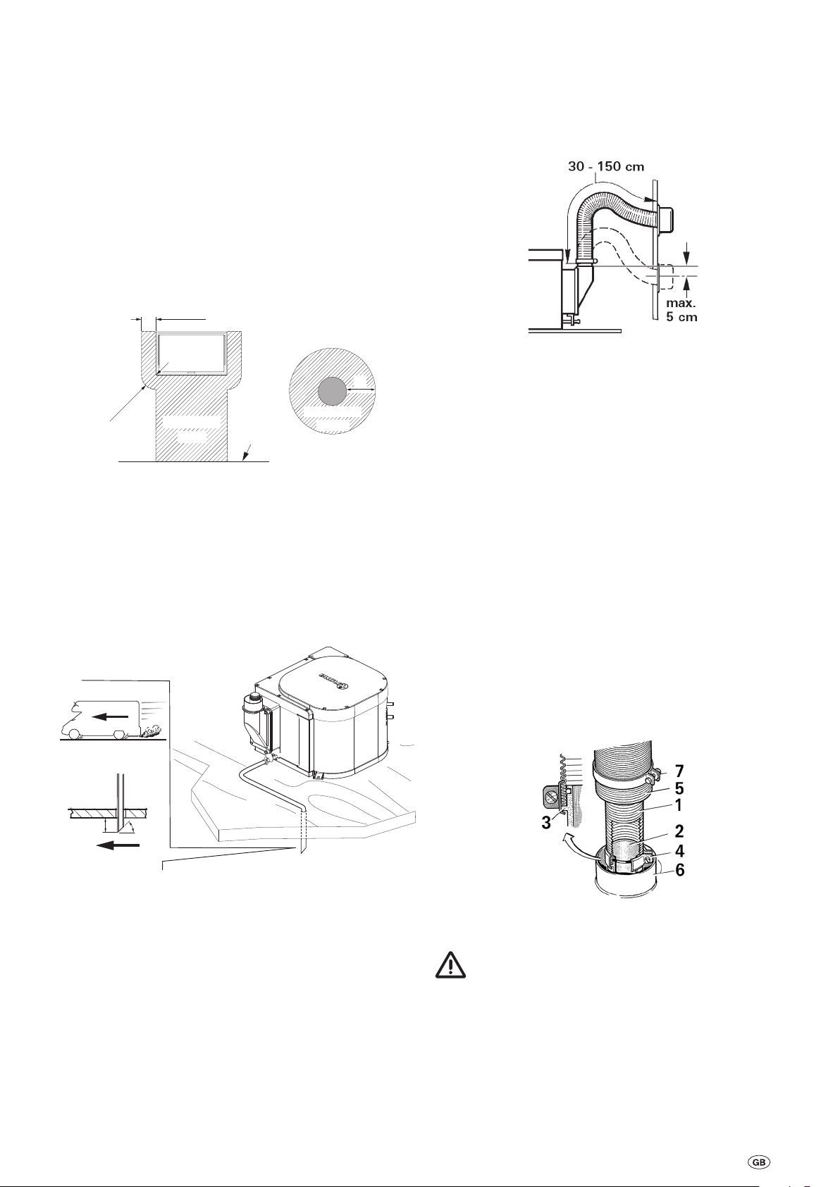
Bild 3
Zulässige Rohrlängen bei Wandkamin:
30 – 150 cm. Rohrlängen bis max. 50 cm können beliebig
steigend oder mit einem Gefälle von max. 5 cm verlegt werden. Um das Eindringen von Wasser weitestgehend zu verhindern, die Rohrverlegung (entsprechend Bild 3) mit einem
Bogen vornehmen.
Bild 1
Der Boiler darf nicht in der Nähe oder direkt hinter einer
Raumheizung eingebaut werden.
Um eine ausreichende Belüftung für die Kühlung der Elektronik zu gewährleisten, sollte der Abstand zwischen der Abdeckung der Elektronik (34) und den Wänden von Möbeln, in die
der Boiler eingebaut wird, mindestens 20mm betragen.
Einbau des Boilers
2
20 mm
Bild 2
Boiler auf einer geeigneten waagrechten Fläche aufstellen.
45º
3
1
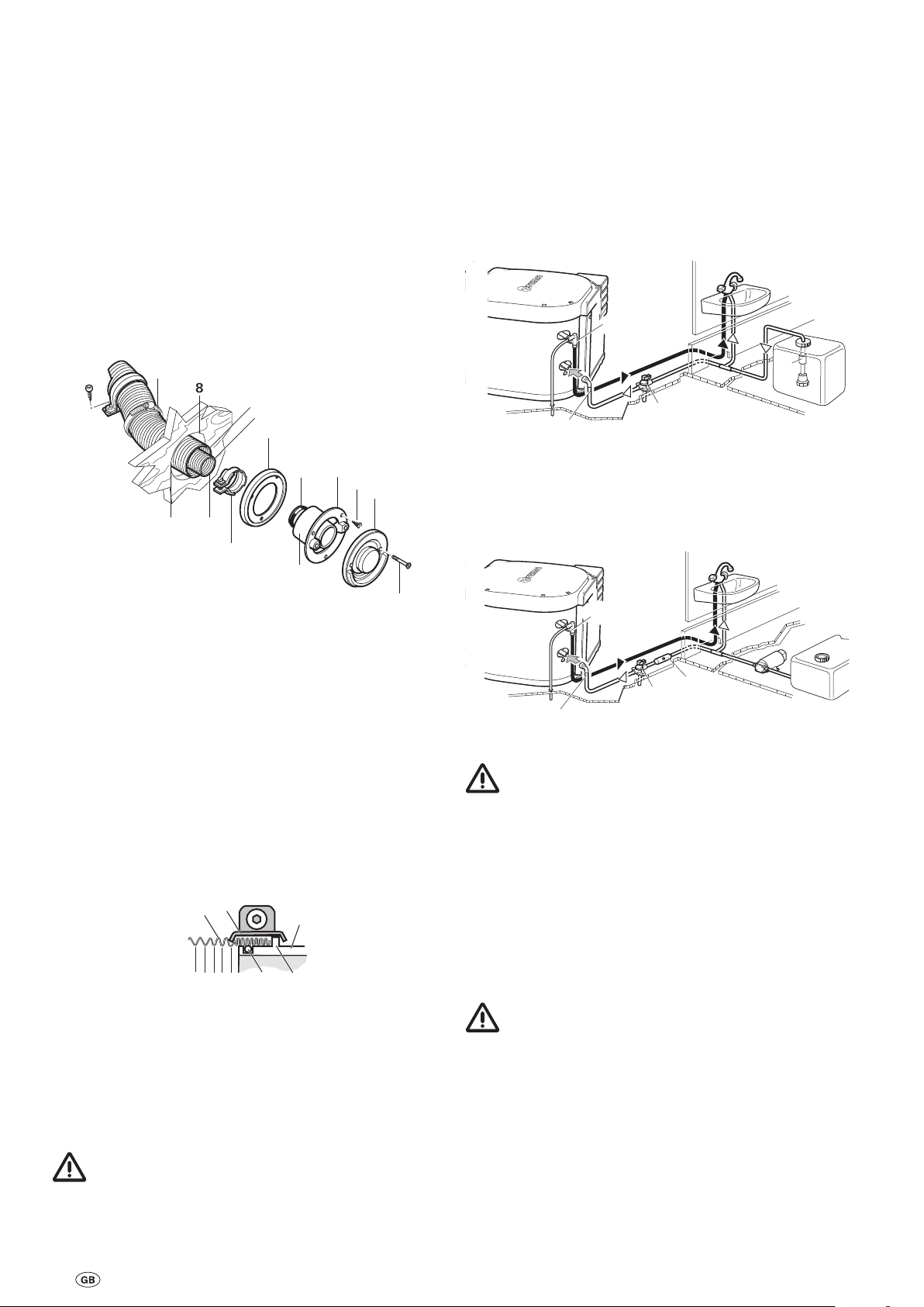
Anschluss Abgas-Doppelrohr ans Gerät
– Schelle (7) über die Rohre schieben.
– Abgasrohr (1) am Anfang zusammenstauchen, dass Win-
dung an Windung liegt.
– Schelle(4) über das Abgasrohr (1) schieben.
– Abgasrohr (1) über den O-Ring (2a) auf den Stutzen (2) bis
zum Bund (3) schieben
– Schelle (4) einhängen und festschrauben. Verbrennungsluft-
zuführungsrohr (5) auf Stutzen (6) mit Schelle (7) befestigen.
Bild 4
Nach jeder Demontage muss ein neuer O-Ring montiert
werden!
Schlauch (2) auf Rohrstutzen 10 mm bis Anschlag aufstecken
und mit Schlauchschelle (3) fixieren. Schlauch (2) fallend
oder waagerecht durch den Caravanboden zur Entwässerung
direkt nach außen führen. Der Schlauch darf nicht geknickt
oder gequetscht werden (gegebenenfalls Schlauchführung
verwenden).
Schlauch ca. 20 mm unter dem Fahrzeugboden 45° schräg
zur Fahrtrichtung abschneiden.
Boiler an den Befestigungslaschen (1) sicher festschrauben.
3

Montage des Wandkamins
14
4
32a
13
Wasseranschluss
Wandkamin an einer möglichst geraden Fläche montieren, die
allseitig vom Wind umströmt werden kann.
– Öffnung (8) mit Ø 70 mm bohren (bei Hohlräumen im Be-
reich der Kaminbohrung mit Holz ausfüttern).
– Abdichtung erfolgt mit beigelegter Gummidichtung (10).
Bei strukturierten Oberflächen mit plastischem Karosserie-Dichtmittel – kein Silikon – bestreichen.
– Bei größeren Wandstärken zuerst Abgas-Doppelrohr von
außen am Kamin anschließen.
– Gummidichtung (10 – glatte Seite zum Kamin, Dichtlip-
pen zur Wand) und Schelle (4) auf das Kamin-Innenteil (11)
schieben.
– Vor dem Durchstecken des Abgas-Doppelrohres durch die
Bohrung, Schelle (7) über die Rohre schieben.
7
8
Ø
70 mm
5
1
10
11
2
4
9
12
13
Für den Betrieb des Boilers können alle Druck- und Tauchpumpen bis zu 2,8bar verwendet werden, ebenso alle Mischbatterien mit oder ohne elektrischem Schalter.
Bei Anschluss an eine zentrale Wasserversorgung (Land-
bzw. City-Anschluss) oder bei der Verwendung leistungsstärkerer Pumpen, muss ein Druckminderer eingesetzt werden,
der verhindert, dass höhere Drücke als 2,8bar im System
auftreten können.
Bei der Verwendung von Tauchpumpen muss ein Rückschlagventil (10–nicht im Lieferumfang) zwischen Pumpe
und der ersten Abzweigung montiert werden (Pfeil zeigt in
Fließrichtung).
12
10
14
Bild 7
Bei Verwendung von Druckpumpen mit großer Schalthysterese kann Heißwasser über den Kaltwasserhahn zurückströmen. Als Rückstromverhinderer empfehlen wir, zwischen dem
Abgang zum Kaltwasserhahn und dem Ablassventil ein Rückschlagventil (11–nicht im Lieferumfang) zu montieren.
Bild 5
Die Rohre so ablängen, dass diese beim Einbau aus der Bohrung für den Kamin herausragen. Das Abgasrohr (1) muss um
10 % länger als das Verbrennungsluft-Zuführungsrohr (5) sein.
Dadurch wird eine Dehnung und Zugbelastung des Abgasrohres vermieden.
– Abgasrohr (1) am Anfang – auf ca.2 cm – zusammenstau-
chen, so dass Windung an Windung liegt.
– Abgasrohr (1) über den O-Ring (2a) auf den Stutzen (2) bis
zum Bund (3) schieben (die Wandkamin-Abwinkelung zeigt
nach oben).
– Schelle (4) so positionieren, dass der Bördelrand der Schelle
um den Bund greift.
– Schelle (4) festschrauben.
1
2
Bild 6
– Kamininnenteil (11) mit 3 Schrauben (12) befestigen (Ein-
baulage beachten! Der Truma Schriftzug muss unten sein).
– Kamin-Außenteil (13) aufsetzen und mit 2 Schrauben (14)
anschrauben.
12
11
14
13
Bild 8
Um eine vollständige Entleerung des Wasserinhaltes im
Boiler und eine Leckagefreiheit aller Wasseranschlüsse
zu gewährleisten, müssen immer die Wasseranschlüsse
(12 + 13) und das Ablassventil (14) verwendet werden!
Flexible Schlauchverlegung
Als Zubehör bietet Truma die Wasseranschlüsse (12+13) und
das Ablassventil (14) mit einem Schlauchanschluss an, Durchmesser 10mm.
Es müssen druckfeste (bis zu 4,5bar), heißwasserbeständige
(bis +80 °C) und lebensmittelechte Wasserschläuche mit einem Innendurchmesser von 10mm verwendet werden.
Wasserschläuche möglichst kurz und knickfrei verle-
gen. Alle Schlauchverbindungen müssen mit Schlauchschellen gesichert werden (auch Kaltwasser)! Durch die
Erwärmung des Wassers und der daraus erfolgenden Ausdehnung können im Ablassventil Drücke bis 4,5bar auftreten
(auch bei Tauchpumpen).
– Verbrennungsluft-Zuführungsrohr (5) auf den gezahnten
Stutzen (9) schiebenund mit Schelle (7) befestigen.
Nach jeder Demontage muss ein neuer O-Ring (2a)
montiert werden!
4
Sämtliche Wasserleitungen fallend zum Ablassventil
verlegen! Anderenfalls Gefahr von Frostschäden, für die
kein Garantieanspruch besteht!
21
Feste Rohrverlegung nach dem John Guest
13
22
20
System
Als Zubehör bietet Truma die Wasseranschlüsse (12+13) und
das Ablassventil(14) mit einen Durchmesser von 12mm an.
Wir empfehlen für diesen Fall ausschließlich die Rohre, Stützhülsen und Sicherungsringe von John Guest zu verwenden.
Für den Anschluss fester Rohrleitungen mit anderem Durchmesser müssen geeignete Adapter (nicht im Lieferumfang)
verwendet werden.
Belüftungsschlauch ca. 20mm unter dem Fahrzeugboden
45°schräg zur Fahrtrichtung abschneiden.
12
Sämtliche Wasserleitungen fallend zum Ablassventil
verlegen! Anderenfalls Gefahr von Frostschäden, für die
kein Garantieanspruch besteht!
Einbau des Ablassventils
Ablassventil(14) an gut zugänglicher Stelle in der Nähe des
Boilers montieren. Loch mit einem Durchmesser von 18mm
bohren und Entleerungsstutzen mit Schlauch(15) durchstecken. Ablassventil mit 2Schrauben befestigen. Die Entwässerung direkt nach außen an spritzwassergeschützter Stelle
vornehmen (ggf. Spritzschutz anbringen).
14
15
Ø 18 mm
Bild 9
Verlegung der Wasserleitungen
Kaltwasserzulauf (16) am Ablassventil(14) anschließen. Es
muss auf keine Fließrichtung geachtet werden.
20
13
20 mm
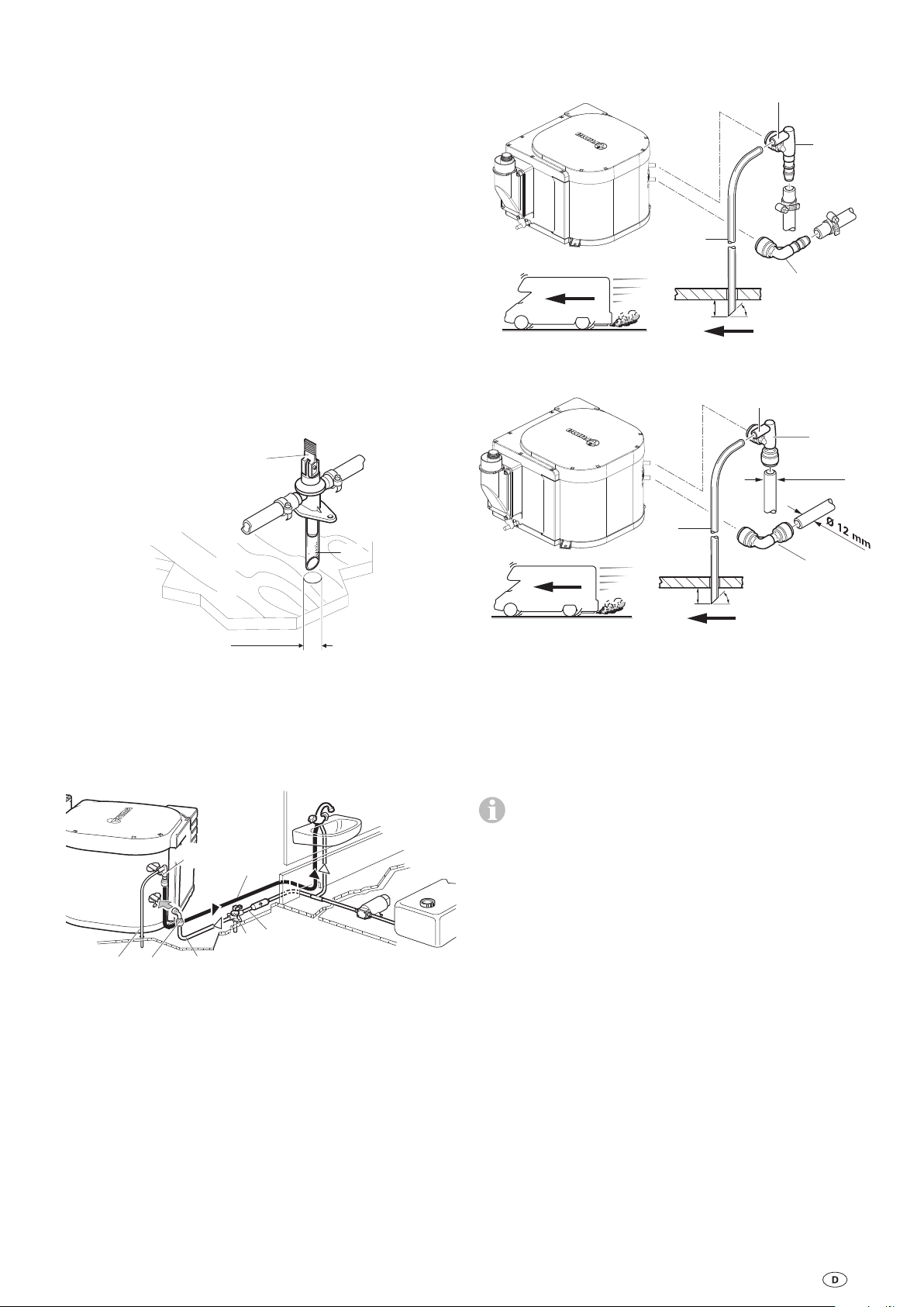
Bild 11 Flexible Schlauchverlegung
20
20 mm
Bild 12 Feste Rohrverlegung
(z. B. John Guest System)
Schlauchverbindung (22) für Kaltwasserzulauf zwischen
Ablassventil (14) und Winkelanschluss (13– unteres Rohr) am
Boiler herstellen.
Die Warmwasserleitung (23) vom Winkelanschluss mit integriertem Belüftungsventil (12–oberes Rohr) zu den Warmwasser-Verbrauchsstellen verlegen.
45º
21
12
Ø 12 mm
13
45º
12
Bild 10
Winkelanschluss ohne Belüftungsventil(13) am Kaltwasser-Anschlussrohr (unteres Rohr) und Winkelanschluss mit
integriertem Belüftungsventil(12) am Warmwasser-Anschlussrohr (oberes Rohr) des Boilers so weit wie möglich
aufschieben. In die entgegengesetzte Richtung ziehen, um zu
überprüfen, ob die Winkelanschlüsse sicher befestigt sind.
Belüftungsschlauch, Außendurchmesser 11mm (20), auf die
Schlauchtülle des Belüftungsventils (21) schieben und knickfrei nach außen verlegen. Hierbei den Radius im Bogen nicht
kleiner als 40mm ausführen.
23
14
16
Beim Einbau einer Wasserversorgung in das Fahrzeug
muss darauf geachtet werden, dass zwischen den Wasserschläuchen und der Wärmequelle (z. B. Heizung, Warmluftrohr) ein ausreichender Abstand eingehalten wird.
Zur Befestigung der Schläuche an Wand oder Boden sind
die Schlauchclips SC (Art.-Nr. 40712-01) geeignet. Diese
Schlauchclips ermöglichen auch eine frostsichere Verlegung
von Wasserschläuchen auf den Warmluftverteilungsrohren
der Heizung.
Ein Wasserschlauch darf erst in einem Abstand von 1,5 m
zur Heizung am Warmluftrohr angelegt werden. Der Truma
Schlauchclip SC kann ab diesem Abstand verwendet werden.
Bei Parallelverlegung, z. B. einer Durchführung durch eine
Wand, muss ein Abstandshalter (z. B. eine Isolierung) angebracht werden, um den Kontakt zu vermeiden.
5

Gasanschluss
Ø 55 mm
33
28
Bild 13
Der Betriebsdruck für die Gasversorgung beträgt
30mbar und muss dem Betriebsdruck des Geräts ent-
sprechen (siehe Typenschild).
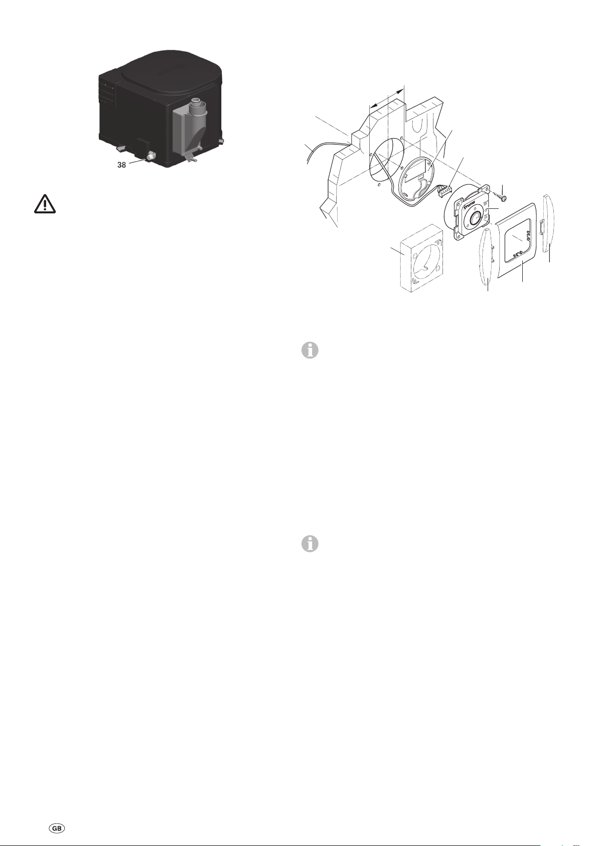
Das Gaszuleitungsrohr, Durchmesser 8mm, muss mit einer
Schneidringverbindung am Anschlussstutzen (38) angeschlossen werden. Die Schneidringe müssen entsprechend dem
verwendeten Gaszuleitungsrohr ausgewählt werden (für Kupferrohre: im Lieferumfang enthaltene Stützhülsen und Schneidring aus Messing). Beim Festziehen sorgfältig mit einem
zweiten Schlüssel gegenhalten!
Montage des Bedienteils
Bei der Platzwahl die Länge des Anschlusskabels (3m) beachten. Bei Bedarf ist eine Kabelverlängerung 5m lieferbar.
29
28
31
26
25
32
33
Vor dem Anschluss an den Boiler sicherstellen, dass die Gasleitungen frei von Schmutz, Spänen und Ähnlichem sind!
Die Rohrverlegung ist so zu wählen, dass für Servicearbeiten
das Gerät wieder ausgebaut werden kann.
In der Gaszuleitung ist die Anzahl der Trennstellen in von Personen benutzten Räumen auf die technisch unvermeidbare
Anzahl zu begrenzen.
Die Gasanlage muss den technischen und administrativen Bestimmungen des jeweiligen Verwendungslandes entsprechen
(z.B. EN1949 für Fahrzeuge). Nationale Vorschriften und Regelungen müssen beachtet werden.
Bild 14
Ist eine Unterputzmontage der Bedienteile nicht möglich,
liefert Truma auf Wunsch einen Aufputzrahmen (25 –
Art.-Nr.40000-52600) als Zubehör.
Ein Loch mit einem Durchmesser von 55mm bohren.
Das Bedienteilkabel (28) am Bedienteil (26) anstecken und
anschließend die hintere Abdeckkappe (29) als Zugentlastung
aufstecken.
Das Kabel nach hinten durchschieben und das Anschlusskabel (28) zum Boiler verlegen.
Das Anschlusskabel mit Steckverbinder (28) zur elektronischen Steuereinheit 12V verlegen (Anschluss siehe „Elektrischer Anschluss 12V“).
Das Bedienteil mit 4Schrauben(31) befestigen.
Die vordere Abdeckung aufstecken (32).
Zum optischen Abschluss der Abdeckrahmen liefert
Truma Seitenteile (33) als Zubehör. Bitte wenden Sie sich
an Ihren Händler.
6

Elektrischer Anschluss 12V
Funktionsprüfung
Vor Beginn der Arbeit an elektrischen Teilen muss das Gerät
von der Stromversorgung abgeklemmt werden. Ausschalten
am Bedienteil reicht nicht!
Bei Elektroschweißarbeiten an der Karosserie muss der Geräteanschluss vom Bordnetz getrennt werden.
Bei Verpolung der Anschlüsse besteht Gefahr von
Kabelbrand. Außerdem erlischt jeder Garantie- oder
Haftungsanspruch.
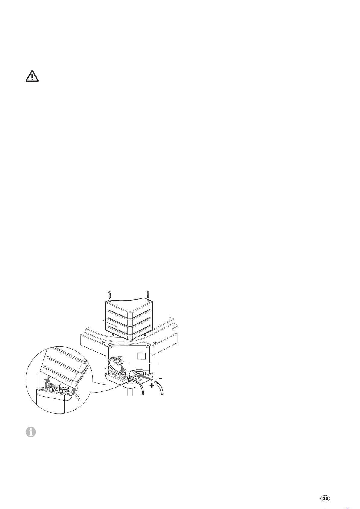
Bedienteilkabel (28) mit Steckverbinder (28a) auf die elektronische Steuereinheit stecken.
Für eine sichere Anbringung das Bedienteilkabel (28) durch
die Kabelführung (28b) führen.
Der elektrische Anschluss 12V erfolgt an der Klemme (35).
orange = plus 12 V
blau = minus
Dazu mit einem kleinen Schraubenzieher von oben andrücken
und Kabel von vorne einschieben.
Am abgesicherten Bordnetz (Zentralelektrik 5–10A) mit einem Kabel 2 x 1,5 mm² anschließen.
Minusleitung an Zentralmasse anschließen. Bei Längen über
6m ein Kabel 2 x 2,5 mm² verwenden. Bei direktem Anschluss an die Batterie muss die Plus- und Minusleitung abgesichert werden.
Nach dem Einbau muss die Dichtigkeit der Gaszuleitung nach
der Druckabfallmethode geprüft werden. Eine Prüfbescheinigung ist auszustellen.
Anschließend alle Funktionen des Gerätes, wie in der Gebrauchsanweisung beschrieben, überprüfen – insbesondere
die Funktion zum Entleeren des Boilers. Es besteht kein
Garantieanspruch für Frostschäden!
Den Boiler niemals ohne Wasserinhalt betreiben! Eine
Überprüfung der elektrischen Funktion ist kurzzeitig auch ohne Wasserinhalt möglich. Vor Inbetriebnahme unbedingt die
Gebrauchsanweisung beachten!
Warnhinweise
Der dem Gerät beiliegende gelbe Aufkleber mit den Warnhinweisen muss durch den Einbauer bzw. Fahrzeughalter an
einer für jeden Benutzer gut sichtbaren Stelle im Fahrzeug
(z.B. an der Kleiderschranktür) angebracht werden! Fehlende
Aufkleber können bei Truma angefordert werden.
Sofern erforderlich, den äußeren Kabelmantel an der Durchführung des Deckels entfernen.
An die Zuleitung dürfen keine weiteren 12 V Verbraucher angeschlossen werden!
Die Boiler-Sicherung (36), 1,6 A, (träge) befindet sich auf
der elektronischen Steuereinheit.
Deckel (34) anschrauben.
34
28a
28b
28
36
35
Bild 15
Bei Verwendung von Netz- bzw. Stromversorgungsgerä-
ten beachten, dass diese eine geregelte Ausgangsspannung zwischen 11V und 15V liefern und die Wechselspannungswelligkeit < 1,2 Vss beträgt.
7

Boiler Gas BGF 10 – Hot water generator
Table of Contents
Symbols used ........................................................................ 8
Installation instructions
Intended use .......................................................................... 8
Regulations ............................................................................ 8
Selecting a location ........................................................... 9
Connecting the exhaust double duct to the device ............... 9
Installing the wall cowl ........................................................ 10
Water connection ............................................................. 10
Flexible hose installation ..................................................... 10
Rigid duct installation using the John Guest system .......... 11
Installing the drain valve ...................................................... 11
Water line routing ................................................................ 11
Gas connection ................................................................. 12
Control panel installation ................................................ 12
12V electrical connection .............................................. 13
Function check ................................................................. 13
Warnings ........................................................................... 13
Symbols used
The device must only be installed and repaired by an
expert.
Symbol indicates possible hazards.
Note containing information and tips.
Installation instructions
The device must only be installed and repaired by an expert. Read the installation instructions carefully before com-
mencing the work, and then comply with them.
Disregarding installation instructions or erroneous
installation can put people in danger and cause
damage to property.
Intended use
This device was designed for installing in caravans, motor
homes and other vehicles. Installation in boats is not permitted. Other applications are permitted subject to prior consultation with Truma.
Regulations
Any modifications to the device (including exhaust duct and
cowl), failure to use original Truma parts as spare parts and
accessories (e.g. time switch) or failure to follow the installation and operating instructions will invalidate the warranty
and no liability will be accepted. The device’s operating permit, and consequently also the vehicle’s operating permit in
some countries, are also rendered void.
The installation of the device in vehicles must comply with
the technical and administrative regulations of the respective
country of use (e.g. EN1949 for vehicles). In other countries,
the relevant regulations must be observed.
8
Selecting a location
300 mm
Exhaust duct
The device must always be installed in such a way that it is
easy to access at all times for service work, and also easy to
remove and install.
Position the boiler in such a way that the cowl can be fitted to
an outer surface that is as straight and smooth as possible.
The wind must be able to flow around this outer surface at all
sides, and no decorative strips or panels should be present
there if possible, otherwise place the boiler on a suitable base.
The wall cowl must be attached such that there is no fuel tank
filler neck or fuel tank breather opening within 500mm (A).
There must also be no living area ventilation openings within
300 mm (A). If the cowl has been placed vertically beneath
an opening window, the boiler must be equipped with an automatic shut-off device in order to prevent operation with the
window open.
Window
A
protected
area
Figure 1
300 mm
protected
area
Floor
Only the Truma AA 24 exhaust duct (part no. 39420-00) and
the ZR24 combustion air intake duct (part no. 39440-00) may
be used for the device , since the device has only been tested
and approved with these ducts.
Do not crush or kink ducts during installation.
Figure 3
Permissible duct lengths with wall cowl:
30 – 150 cm. Duct lengths of up to 50 cm can be laid with any
amount of upslope or with a downslope of max. 5 cm. To prevent the ingress of water as much as possible, lay the ducts
(as shown in Figure 3) in a curve.
The boiler must not be installed close to or directly behind a
room heater.
In order to ensure that there is sufficient ventilation to cool
the electronics, the gap between the electronics cover (34)
and the walls of furniture items in which the boiler is installed
must be at least 20mm.
Installing the boiler
3
1
20 mm
Figure 2
2
45º
Connecting the exhaust double duct to the
device
– Push the clamp (7) over the ducts.
– Compress the exhaust duct (1) at its beginning so that the
coils are lying against each other.
– Slide the clamp (4) over the exhaust duct (1).
– Slide the exhaust duct (1) over the O-ring (2a) on the con-
nection (2) as far as the collar (3).
– Hook in the clamp (4) and screw it securely into place. Slide
the combustion air intake duct (5) onto the connection (6)
and secure with the clamp (7).
Set up the boiler on a suitable horizontal surface.
Attach the hose (2) to the 10 mm duct connection as far as
possible and fix it with a hose clamp (3). Lay the hose(2)
downwards or horizontally through the caravan floor to
drain directly to the outside. The hose must not be bent or
squeezed (use a hose guide if necessary).
Cut off the hose about 20 mm below the vehicle floor at a
45°angle relative to the direction of travel.
Securely screw the boiler to the retaining bracket (1).
Figure 4
A new O-ring must be fitted whenever the exhaust duct
has been removed!
9
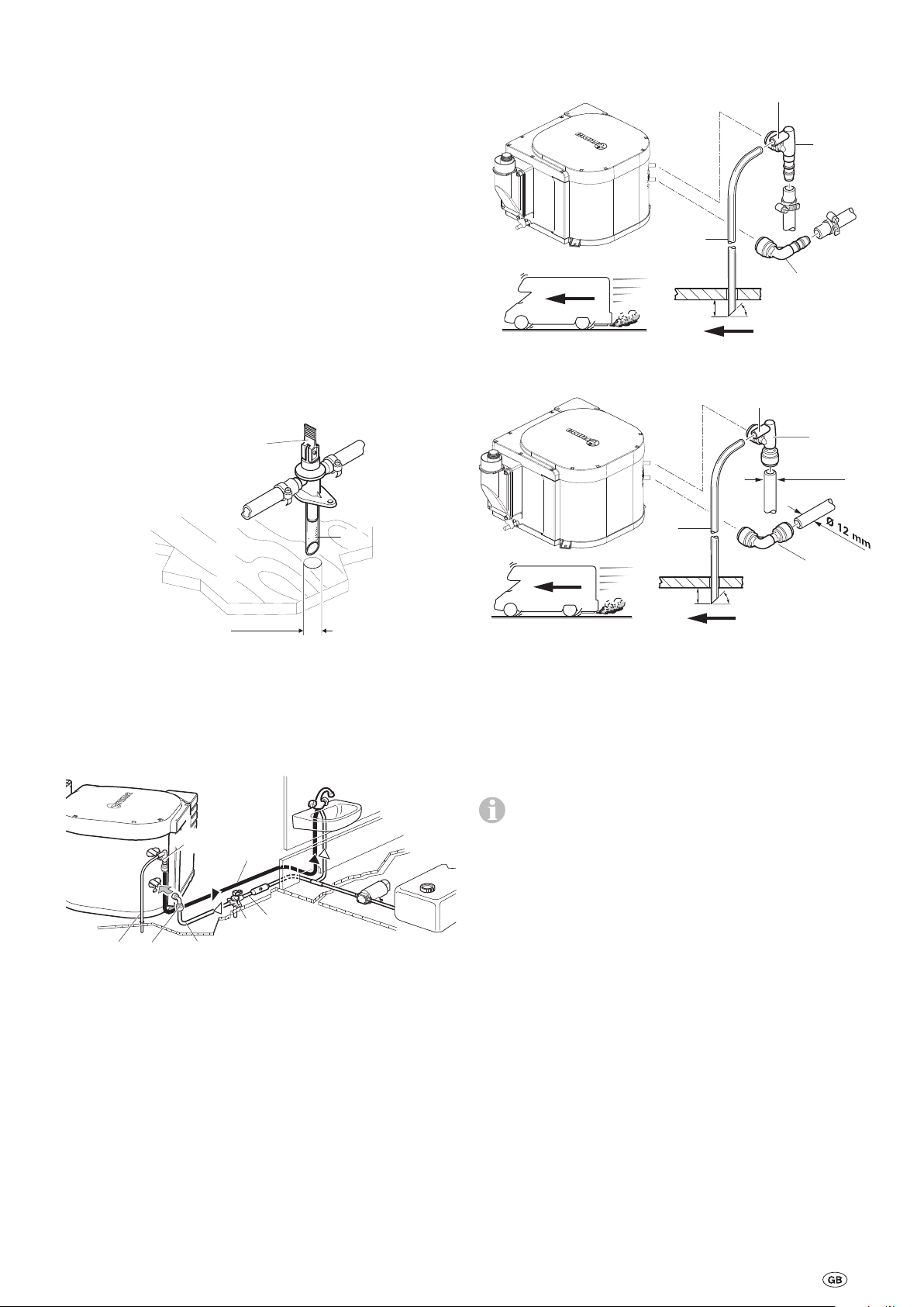
Installing the wall cowl
14
4
32a
13
Water connection
Fit wall cowl to a surface that is as flat as possible so that air
can flow around at all sides.
– Drill opening (8) with a diameter of 70 mm (duct hole must
be lined with wood in cavities).
– Seal with provided rubber seal (10). Use flexible body seal-
ant on textured surfaces – do not use silicon.
– In the case of thicker walls, first connect the exhaust double
duct to the cowl from the outside.
– Slide rubber seal (10 – smooth side towards cowl, seal-
ing lips towards wall) and clamp (4) onto inner part of
cowl (11).
– Before pushing the exhaust double duct through the hole,
slide clamp (7) over duct.
7
8
Ø
70 mm
5
1
10
11
2
4
9
12
13
Any pressure or immersion pump up to 2.8 bar can be used to
operate the boiler, as can any mixing battery with or without
an electric switch.
If connected to a central water supply (rural or urban connection), or if more powerful pumps are being used, a pres-
sure reducer must be used, which will prevent pressures
higher than 2.8 bar from occurring in the system.
If using immersion pumps, a non-return valve (10–not included in scope of delivery) must be installed between the
pump and the first branch (arrow indicates flow direction).
12
10
14
Figure 7
When pressure pumps with a large switching hysteresis are
being used, hot water may flow back via the cold water valve.
We recommend installing a non-return valve (11–not included in scope of delivery) between the outlet to the cold water
tap and the drain valve as a return flow inhibitor.
Figure 5
The ducts must be cut to length so that they protrude from
the hole for the cowl after installation. The exhaust duct (1)
must be 10 % longer than the combustion air intake duct (5).
This avoids exhaust duct expansion and tensile load.
– Compress the beginning of the exhaust duct (1) (approx.
2cm thereof) so that the coils are lying against each other.
– Push the exhaust duct (1) over the O-ring (2a) and onto the
connection (2) as far as the collar (3) (the wall cowl angle
faces upwards).
– Position the clamp (4) so that the flanged rim of the clamp
is gripping the collar.
– Screw the clamp (4) securely into place.
1
2
Figure 6
– Secure the cowl inner part (11) with 3 screws (12) (pay at-
tention to the installation position – the Truma logo must be
at the bottom).
– Fit outer part of cowl (13) and screw it on with 2 screws (14).
12
11
14
13
Figure 8
In order to ensure that all the water is drained from the
boiler and that all water connections are leak-tight, the
water connections (12 + 13) and the drain valve (14) must
always be used.
Flexible hose installation
Truma can supply the water connections (12+13) and the
drain valve (14) with hose connection, diameter 10mm, as
accessories.
Pressure-resistant (up to 4.5bar), hot water-resistant (up to
+80 °C) , food-safe water hoses with an inner diameter of
10mm must be used.
Water hoses must be as short as possible and free of
kinks. All hose rubber connections must be secured
with hose clamps (including the cold water connection). The
warming of the water and its resulting expansion may generate pressures of up to 4.5bar in the drain valve (also occurs
with immersion pumps).
– Slide combustion air intake duct (5) onto serrated connec-
tion (9) and secure with clamp (7).
A new O-ring (2a) must be fitted whenever the exhaust
pipe has been removed.
10
Route all water lines so they slope downwards to the
drain valve. Otherwise there is a risk of frost damage
that is not covered by the warranty!
21
Rigid duct installation using the John Guest
13
22
20
system
Truma can supply the water connections (12+13) and the
drain valve (14) with a diameter of 12mm as accessories. In
this case it is advisable to always use John Guest pipes, insertion sleeves and locking rings.
Suitable adapters (not included in scope of delivery) must be
used for connecting rigid pipelines with a different diameter.
Route all water lines so they slope downwards to the
drain valve. Otherwise there is a risk of frost damage
that is not covered by the warranty!
Installing the drain valve
Fit drain valve(14) in an easily accessible location in the vicinity of the boiler. Drill hole with diameter of 18mm and insert
the drainage socket with hose(15). Secure the drain valve in
place with 2screws. Water removal can take place directly to
the outside in a splash-protected location (fit splash guards if
necessary).
Cut off the venting hose about 20mm below the vehicle floor
at a 45° angle relative to the direction of travel.
12
20
13
20 mm
Fig. 11 Flexible hose installation
45º
21
14
15
Ø 18 mm
Figure 9
Water line routing
Connect cold water supply(16) to drain valve(14). The direction of flow is irrelevant.
12
Figure 10
Push elbow fitting without aeration valve(13) as far as possible onto the boiler’s cold water connection tube (lower tube),
and push the elbow fitting with built-in aeration valve(12) as
far as possible onto the boiler’s hot water connection tube
(upper tube). Pull in the opposite direction to check that the
elbow fittings are securely attached.
23
14
16
12
Ø 12 mm
20
13
20 mm
Fig. 12 Rigid pipe installation
(e.g. John Guest System)
Manufacture a hose connection (22) for the cold water supply
between the drain valve (14) and the elbow fitting (13– lower
tube) at the boiler.
Route hot water supply line (23) from elbow fitting with builtin aeration valve (12–upper tube) to hot water consumption
points.
If a water supply is being installed in the vehicle, it must
be ensured that sufficient room is left between the water
hoses and the heat source (e.g. heater, warm air duct).
SC hose clips (part no. 40712-01) are suitable for fastening
the hoses to walls or the floor. These hose clips also make it
possible to route water hoses on the heater’s warm air distribution pipes to prevent freezing.
A water hose may only be routed at a distance of 1.5 m from
the heater at the warm air duct. The Truma SC hose clip can
be used for distances greater than this. With parallel routing
(e.g. through a wall) a spacer (e.g. insulation) must be fitted in
order to avoid contact.
45º
Slide venting hose with an outer diameter of11mm (20) onto
the hose nozzle of the aeration valve (21) and route to the outside free of kinks. Radius of arc must not be less than 40 mm.
11
Gas connection
Ø 55 mm
33
28
Control panel installation
Make allowance for the length of the connector cable (3m)
when choosing a location. A 5m cable extension is available
if necessary.
29
28
Figure 13
The operating pressure of the gas supply is 30 mbar
and must be the same as the operating pressure of the
device (see type plate).
The 8 mm diameter gas supply pipe must be attached to the
connection (38) using an olive connection. The olives must be
selected according to the gas supply pipe used (for copper
pipes: brass insertion sleeves and olive included in scope of
delivery). Carefully counterhold with another wrench when
tightening.
Before connecting to the boiler, ensure that the gas lines are
free of dirt, swarf and the like.
The pipes must be installed in such a way that the device can
be removed again for service work.
The number of separation points in the gas supply line in
rooms used by persons must be limited to the technical
minimum.
The gas system must comply with the technical and administrative regulations of the respective country of use (e.g.
EN 1949 for vehicles). National regulations and rules must be
followed.
31
26
25
32
33
Figure 14
If the control panels cannot be flush-mounted, Truma can
provide an on-surface frame (25 – part no. 40000-52600)
as an accessory by request.
Drill a hole with a diameter of 55mm.
Connect the control panel cable (28) to the control panel (26)
and then connect the rear blank cover (29) as strain relief.
Push the cable through towards the rear and route the connector cable (28) to the boiler.
Route the connector cable with the connector (28) to the 12V
electronic control unit (for connection, see “12V electrical
connection”).
Secure the control panel with 4 screws (31).
Fit the front cover (32).
Truma supplies side parts (33) as accessories to improve
the appearance of the cover frames. Please contact your
dealer.
12
12V electrical connection
Function check
Disconnect device from power supply before starting to work
on electrical components. Switching off at the control panel is
insufficient!
The device must be disconnected from the on-board power
supply when electric welding work is being carried out on the
vehicle body.
Reversing the polarity of the connections will result in
a risk of cable fire. Any warranty or liability claims will
also be invalidated.
Plug the control panel cable (28) with the connector (28a) into
the electronic control unit.
In order to attach it securely, route the control panel cable (28)
through the cable guide (28b).
The 12V electrical connection is made at the clamp (35).
orange = positive 12 V
blue = negative
This is done by pressing from above with a small screwdriver
and pushing the cable in from the front.
Connect to the fuse-protected on-board power supply (central
electrical system 5–10A) using a 2x1.5mm² cable.
Connect negative line to main ground connection. For lengths
of over 6m, use a 2 x 2.5 mm² cable. If the equipment is connected directly to the battery, the positive and negative lines
must be protected.
The leak tightness of the gas supply line must be tested using
the pressure drop method after installation. A test certificate
must be issued.
Then check all device functions as described in the operating instructions – especially the boiler draining function. No
claims may be made under the warranty for damage
caused by frost!
Never operate the boiler when it is empty. An electrical
function check can be carried out briefly even if there is no
water in the boiler. Always follow the operating instructions
before starting up.
Warnings
The installer or vehicle owner must affix the yellow sticker
with the warning information, which is enclosed with the appliance, in a location in the vehicle where it is clearly visible
to all users (e.g. the wardrobe door). Missing stickers can be
requested from Truma.
If necessary, remove the outer cable sheathing at the cover
leadthrough.
No other 12V consumers must be connected to the supply
line.
The boiler fuse (36), 1.6 A (slow-acting), is on the electronic
control unit.
Screw on the cover (34).
34
28a
28b
28
36
35
Figure 15
When power packs or power supply units are being
used, note that the regulated output voltage is between
11V and 15V and the alternating current ripple is < 1.2Vpp.
13
Boiler Gas BGF 10 – Chauffe-eau
Table des matières
Symboles utilisés ................................................................. 14
Instructions de montage
Utilisation ............................................................................ 14
Prescriptions ........................................................................ 14
Choix de l’emplacement .................................................. 15
Raccordement du double tuyau de cheminée à l’appareil .. 15
Montage de la cheminée latérale ........................................ 16
Raccordement d’eau ........................................................ 16
Pose de tuyaux flexibles ...................................................... 16
Pose de tuyaux rigides selon le système JohnGuest .......... 17
Montage de la soupape de vidange .................................... 17
Pose des conduites d’eau .................................................... 17
Raccordement au gaz ...................................................... 18
Montage de la pièce de commande .............................. 18
Connexion électrique 12V .............................................. 19
Vérification du fonctionnement ..................................... 19
Remarques d’avertissement ........................................... 19
Symboles utilisés
Le montage et la réparation de l’appareil doivent être
effectués uniquement par un spécialiste.
Ce symbole indique des risques possibles.
Remarque avec informations et conseils.
Instructions de montage
Le montage et la réparation de l’appareil doivent être
effectués uniquement par un spécialiste. Avant de com-
mencer les travaux, lire soigneusement et respecter les instructions de montage.
Le non-respect des instructions de montage ou
un mauvais montage peut provoquer une mise en
danger de personnes et des dommages matériels.
Utilisation
Cet appareil a été conçu pour le montage dans les caravanes,
les camping-cars et autres véhicules. Le montage dans les
bateaux est interdit. D’autres applications sont admissibles
après consultation de Truma.
Prescriptions
Toute modification sur l’appareil (y compris le guidage de
gaz brûlés et la cheminée), l’utilisation de pièces autres que
des pièces originales Truma en tant que pièces de rechange
et accessoires (par exemple minuterie), le non-respect des
instructions de montage et du mode d’emploi invalident les
droits à garantie et entraînent l’exclusion de toute demande
de réparation du préjudice subi. En outre, l’autorisation d’utiliser l’appareil est annulée et entraîne dans de nombreux pays
l’annulation de l’autorisation pour tout le véhicule.
Le montage dans des véhicules doit répondre aux dispositions
techniques et administratives du pays d’utilisation respectif
(par exemple EN 1949 pour les véhicules). Hors Allemagne,
les prescriptions en vigueur des pays respectifs doivent être
respectées.
14
 Loading...