


Battery Charger BC 430 IU
Gebrauchsanweisung Seite 2
Einbauanweisung Seite 6
Im Fahrzeug mitzuführen!
Operating instructions Page 8
Installation instructions Page 11
To be kept in the vehicle!
Mode d‘emploi Page 14
Instructions de montage Page 18
À garder dans le véhicule !
Istruzioni per l‘uso Pagina 20
Istruzioni di montaggio Pagina 24
Da tenere nel veicolo!
Gebruiksaanwijzing Pagina 26
Inbouwhandleiding Pagina 30
Im vertuig meenemen!
Brugsanvisning Side 32
Monteringsanvisning Side 36
Skal medbringes i køretøjet!
Instrucciones de uso Página 38
Instrucciones de montaje Página 42
¡
Llévalas en el vehículo!
Bruksanvisning Sida 44
Monteringsanvisning Sida 48
Skall medföras i fordonet!
Komfort für Unterwegs
Ladeautomat BC 430 IU
Inhaltsverzeichnis
Gebrauchsanweisung
Glossar .................................................................................. 2
Verwendete Symbole ............................................................ 2
Sicherheitshinweise .......................................................... 2
Verwendungszweck .............................................................. 3
Bestimmungswidriger Gebrauch
Beschreibung ...................................................................... 3
Anschlüsse .......................................................................... 3
Ladevorgang ....................................................................... 3
Wartung ............................................................................... 4
Entsorgung ............................................................................ 4
Technische Daten
Abmessungen / Gewicht ....................................................... 4
Ladekennlinie ...................................................................... 4
Fehlersuchanleitung .......................................................... 4
Zubehör ................................................................................ 5
Truma Hersteller Garantieerklärung
Einbauanweisung
Sicherheitshinweise .......................................................... 6
Aufstellen ............................................................................ 6
Handhabung der Käfigzugfederklemmen
Anschluss ............................................................................ 6
Leitungslängen und -querschnitte ........................................ 6
Anschlussplan .................................................................... 7
Inbetriebnahme .................................................................. 7
Netzbetrieb auf Fähren ......................................................... 7
Generatorbetrieb .................................................................. 7
............................................................... 4
.................................... 3
............................... 5
...................... 6
Gebrauchsanweisung
Vor Anschluss und Inbetriebnahme des Gerätes unbedingt die Einbau- und Gebrauchsanweisung lesen!
Glossar
AGM-Batterie Blei-Säure-Batterie, bei der der
Elektrolyt in einem Mikroglasvlies
(absorbed glass mat) festgelegt ist.
Batterie OPTIMA® YT S entspricht einer AGM-Batterie.
Verwendete Symbole
Symbol weist auf mögliche Gefahren hin.
Hinweis mit Informationen und Tipps.
Sicherheitshinweise
Beim Gebrauch von elektrischen Geräten sind zum
Schutz vor elektrischem Schlag, Verletzung und Brandgefahr folgende grundsätzliche Sicherheitsmaßnahmen zu
beachten. Lesen und beachten Sie diese Hinweise, bevor Sie
das Gerät benutzen.
Aufstellen
Achten Sie darauf, dass die Geräte sicher aufgestellt werden
und nicht herabfallen oder umstürzen können. Legen Sie
Leitungen stets so, dass keine Stolpergefahr entsteht. Setzen
Sie Elektrogeräte nicht dem Regen aus. Betreiben Sie Elektrogeräte nicht in feuchter oder nasser Umgebung. Betreiben Sie
Elektrogeräte nicht in der Nähe von brennbaren Flüssigkeiten
oder Gasen. Stellen Sie Ihre elektrischen Geräte so auf, dass
Kinder keinen Zugriff darauf haben.
Schutz vor elektrischem Schlag
Betreiben Sie nur Geräte deren Gehäuse und Leitungen unbeschädigt sind. Achten Sie auf sichere Verlegung der Kabel.
Ziehen Sie nicht an den Kabeln.
Den elektrischen Anschluss der Geräte über einen
Fehlerstromschutzschalter 30 mA Nennfehlerstrom
absichern und nur so betreiben. EVU-Vorschriften
beachten.
Gebrauch
Benutzen Sie keine elektrischen Geräte entgegen dem, vom
Hersteller angegebenen Verwendungszweck.
Instandsetzung
Nehmen Sie keine Instandsetzungsarbeiten oder Veränderungen am Gerät vor. Wenden Sie sich an Ihren Händler oder
an den Truma Service (siehe Serviceheft oder www.truma.com).
Zubehör
Benutzen Sie nur Zubehörteile und Zusatzgeräte die vom Hersteller geliefert oder empfohlen werden.
2
+
_
Failure
Trickle charge
Absorption charge
--
--
Bulk charge
neg.
Battery
sense
Temp. sensor
battery
Battery
Battery
Liquid
Gel/AGM
Panel BC
B+
230 V/50 Hz
1 2 3 754 6
Verwendungszweck
Anschlüsse
Der Ladeautomat dient ausschließlich dem Laden von 12 V
Bleiakkumulatoren, bestehend aus 6 Einzelzellen (z. B. Auto
batterie), mit einer Kapazität von 100 – 300 Ah. Er ist universell
einsetzbar und für Dauerbetrieb und Parallelbetrieb ausgelegt.
Das bevorzugte Einsatzgebiet des Ladeautomaten sind Batterien mit Gel-, AGM oder Flüssigelektrolyt. Der Ladeautomat
ist besonders für den Einsatz in Booten, Reisemobilen und
Wohnwagen geeignet. Der Ladeautomat darf nur in trockenen
Räumen betrieben werden.
Bestimmungswidriger Gebrauch
Nicht für 6 V Batterien, oder nichtaufladbare Batterien
verwenden!
Der Ladeautomat darf nicht zum Laden von 6 V Bleiakkumu
latoren verwendet werden. Werden Batterien mit einer Nennspannung von 6 V mit dem Ladeautomat geladen, so setzt die
Gasung sofort ein. Es entsteht explosives Knallgas.
Der Ladeautomat darf nicht zum Laden von nichtaufladbaren
Batterien und / oder Nickel-Cadmium-Batterien verwendet
werden.
Beim Laden dieser Batteriearten, mit dem Ladeautomat, kann
die Hülle explosionsartig aufplatzen.
Beschreibung
Der Ladeautomat ist ein Produkt modernster, mikroprozessorgesteuerter Ladetechnik. Diese Technik ermöglicht hohe
Leistung bei geringem Gewicht und kleinen Abmessungen.
Durch Verwendung hochwertiger Elektronik arbeitet er mit
einem hohen Wirkungsgrad. Das automatische Laden erfolgt
schonend und ohne schädliches Überladen der Batterie. So
wird die Lebensdauer der Batterie wesentlich verlängert. Nach
Herstellen des Batterieanschlusses und des Netzanschlusses
ist der Ladeautomat in Betrieb.
Der Ladeautomat ist für Dauerbetrieb und Parallelbetrieb
konzipiert. Verbraucher können ständig angeschlossen bleiben, dazugeschaltet oder weggeschaltet werden. Es werden
gleichzeitig die Verbraucher versorgt und die Batterie geladen.
Der Verbraucherstrom soll hierbei kleiner als der max. Ladestrom sein, da sonst keine Ladung der Batterie erfolgt.
Unter Verwendung eines Ladekontroll-Panels, z. B. dem Truma
Panel BC (430, 630, 860) können die einzelnen Ladephasen
der Batterie angezeigt werden. Auch eventuelle Störungen
des Ladeautomaten werden auf dem Truma
Panel BC (430, 630, 860) angezeigt.
Wird der Ladeautomat zusammen mit einem Temperaturfühler
für die Batterie betrieben so regelt der Ladeautomat die Ladespannung automatisch in Abhängigkeit der Batterietemperatur. Hierdurch wird eine besonders effektive und schonende
Ladung der Batterie erreicht. Ohne Verwendung eines Temperaturfühlers regelt der Ladeautomat den Ladevorgang wie bei
einer Batterietemperatur von 20 °C.
Das Gerät ist für den Betrieb in einer Umgebungstemperatur
bis 35 °C ausgelegt. Steigt die Geräteinnentemperatur durch
mangelnde Luftzirkulation oder zu hohe Umgebungstemperatur, so reduziert sich der Ladestrom automatisch stufenweise.
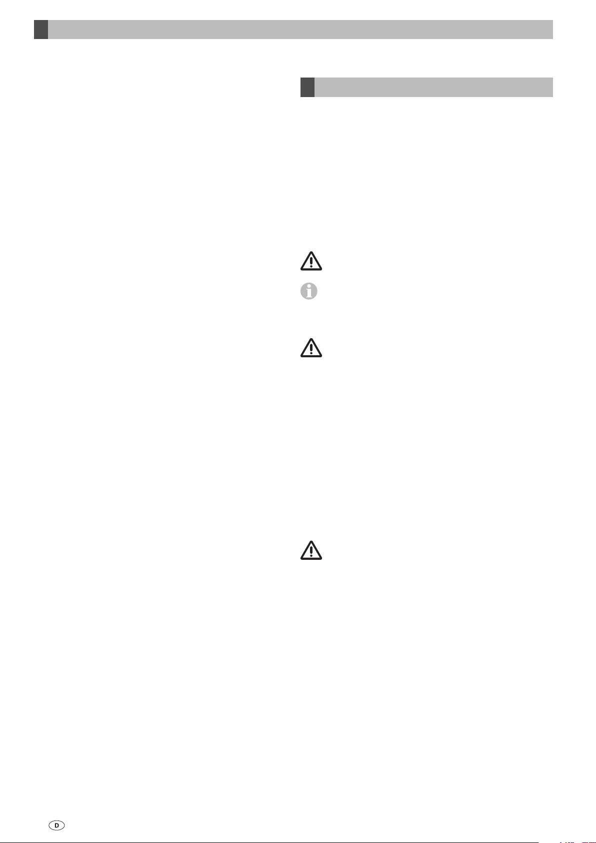
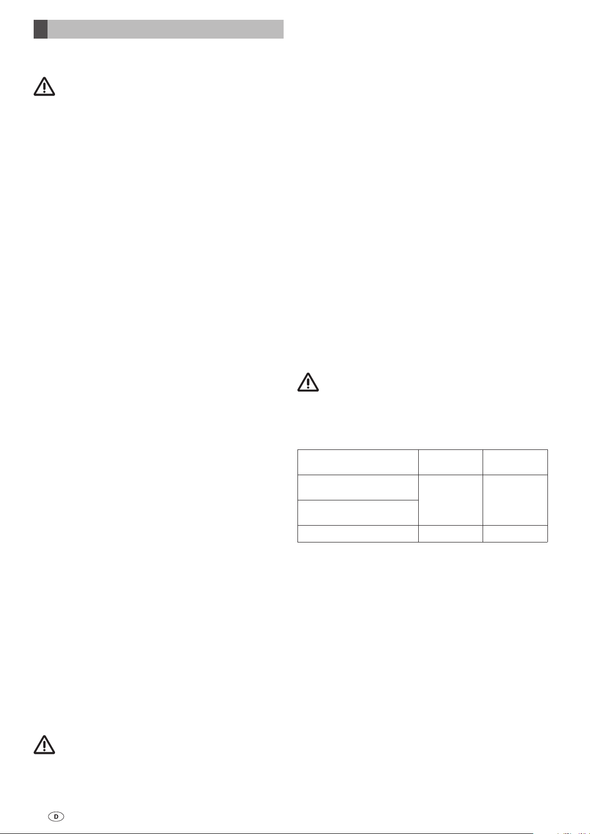
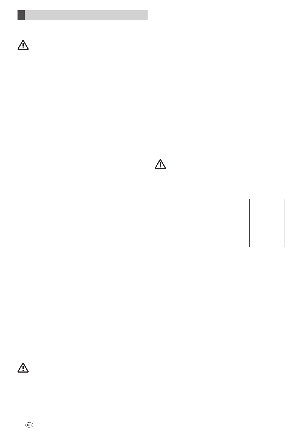
Bild 1: Anschlüsse
1 Kaltgerätesteckeranschluss 230 V ~
2 Anschluss für Ladekontroll-Panel
3 Eingang B+ Messleitung von Batterie
4 Ausgang + Ladeleitung Batterie
-
5 Ausgang
Ladeleitung Batterie
6 Anschluss für Temperaturfühler
7 Umschalter Gel- bzw. AGM (OPTIMA® YT S) /
Flüssigelektrolytbatterie
Ladevorgang
Der Ladeautomat besitzt einen elektronischen Verpolungsschutz. Nur wenn die Batterie richtig angeschlossen ist und
eine Mindestspannung von 1,5 V anliegt, wird der Ladestrom
freigegeben. Während des Ladevorgangs wird die Batteriespannung ständig über die B+ Messleitung überwacht. Der
Ladevorgang erfolgt gemäß der Ladekennlinie unter geringster Verlustleistung (Ladekennlinie siehe Bild 2).
Hauptladephase
(alle Spannungswerte bezogen auf 20 °C Batterietemperatur)
Ladung mit maximalem konstanten Ladestrom bis annähernd
14,4 V Batteriespannung erreicht sind. Sinkt in diesem Bereich
der Hauptladephase der Ladestrom bedingt durch den Batterieinnenwiderstand und Leitungswiderstände unter 90 % des
Nennstromes ab, wird die Nachladephase gestartet.
Nachladephase
(alle Spannungswerte bezogen auf 20 °C Batterietemperatur)
Die Ladespannung wird über eine Zeitdauer von zehn Stunden bei Gel-Batterien / AGM bzw. vier Stunden bei Flüssige
lektrolytbatterien konstant auf 14,4 V gehalten. Nach Ablauf
dieser Zeit erfolgt eine Umschaltung in die Erhaltungsladephase. Steigt während dieser Zeit der Strom auf über 90 %
des Nennstromes und sinkt dabei die Batteriespannung für
einen Zeitraum von mehr als 15 Minuten bei Flüssigelektro
lytbatterien und mehr als zwei Stunden bei Gel-Batterie und
AGM unter 13,2 V, so erfolgt eine Umschaltung zurück in die
Hauptladephase.
Erhaltungsladephase
(alle Spannungswerte bezogen auf 20 °C Batterietemperatur)
Die Ladespannung ist auf 13,8 V eingestellt. Der Ladestrom
sinkt dabei auf den für die Batterie zur Ausgleichsladung
notwendigen Wert ab. Steigt der Ladestrom bedingt durch
Verbraucher auf seinen Nennwert und sinkt die Batteriespannung für mindestens zwei Minuten unter 13,2 V, so schaltet
das Gerät wieder in die Hauptladephase zurück.
Parallelbetrieb
Wird während der Nachladephase oder der Erhaltungsladephase Verbraucherstrom entnommen, so wird dieser sofort
nachgeladen.
-
-
3
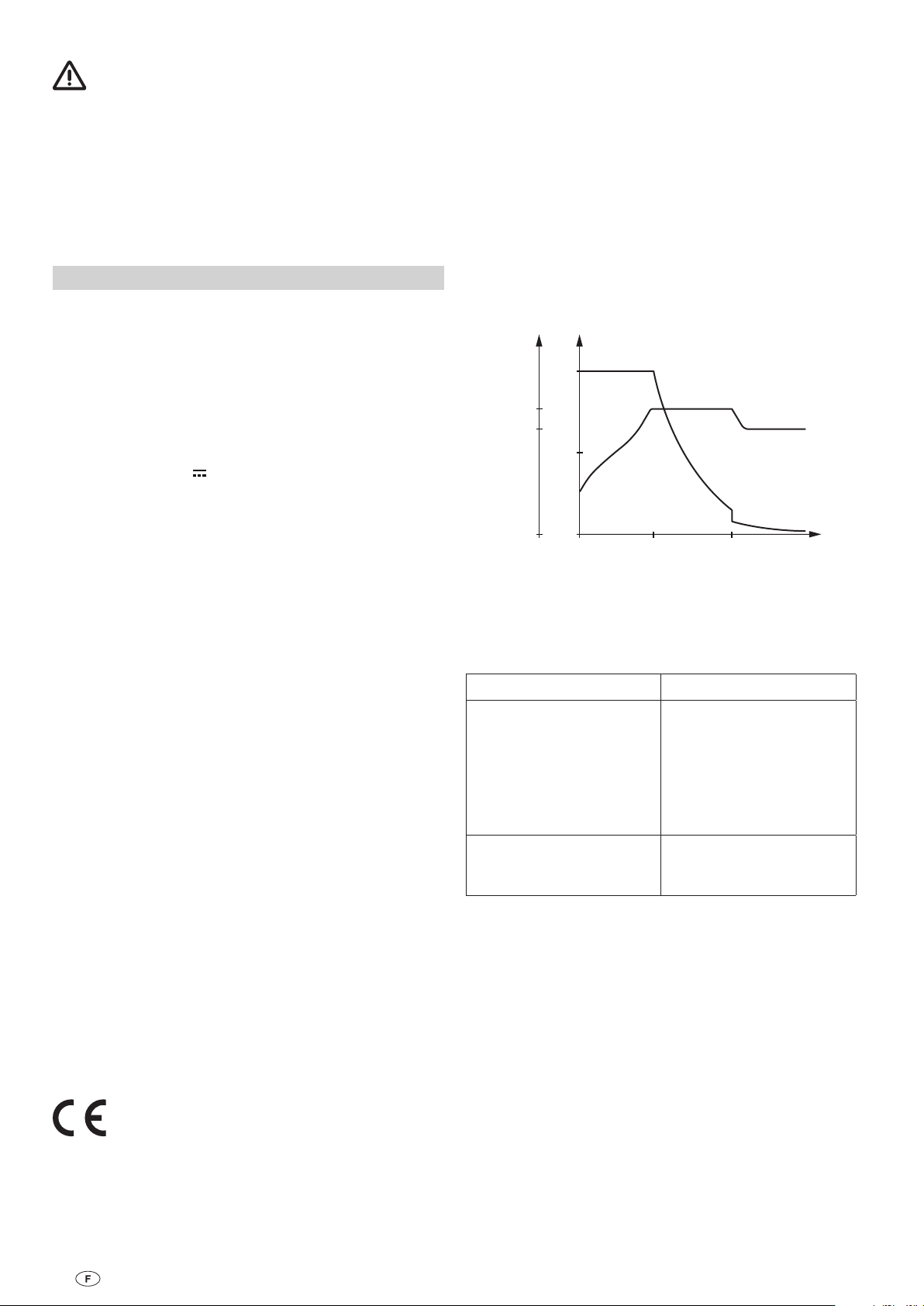
13. 8
0
U[ V]
14. 4
0
50
100
I[%]
I
U
t[h]ELNLHL
Wartung
Abmessungen / Gewicht
Vor allen Wartungsarbeiten am Gerät unbedingt die
Stromzufuhr unterbrechen.
Reinigen Sie das Gerät und die Lüftungsschlitze mit einem trockenen, fusselfreien Tuch.
Entsorgung
Das Gerät ist gemäß den administrativen Bestimmungen des
jeweiligen Verwendungslandes zu entsorgen. Nationale Vorschriften und Gesetzte müssen beachtet werden.
Technische Daten
Spannungsversorgung
Wechselspannung 230 V / 50 Hz, einphasig
Bereich ca. 195 V – 250 V / 50 – 60 Hz
Ausgangsstrom (Ladestrom Batterie)
Ladestrom max. 30 A, arithmetischer Mittelwert, elektronisch
geregelt entsprechend der Ladekennlinie IUoU
Ausgangsspannung
Gleichspannung 12 V
Ladevorgang
Automatisch
Gehäuse
Aluminium, lackiert, belüftet
Länge
302 mm (ohne Füße)
Breite
173 mm (ohne Füße)
Höhe
100 mm
Gewicht
3 kg (30 N)
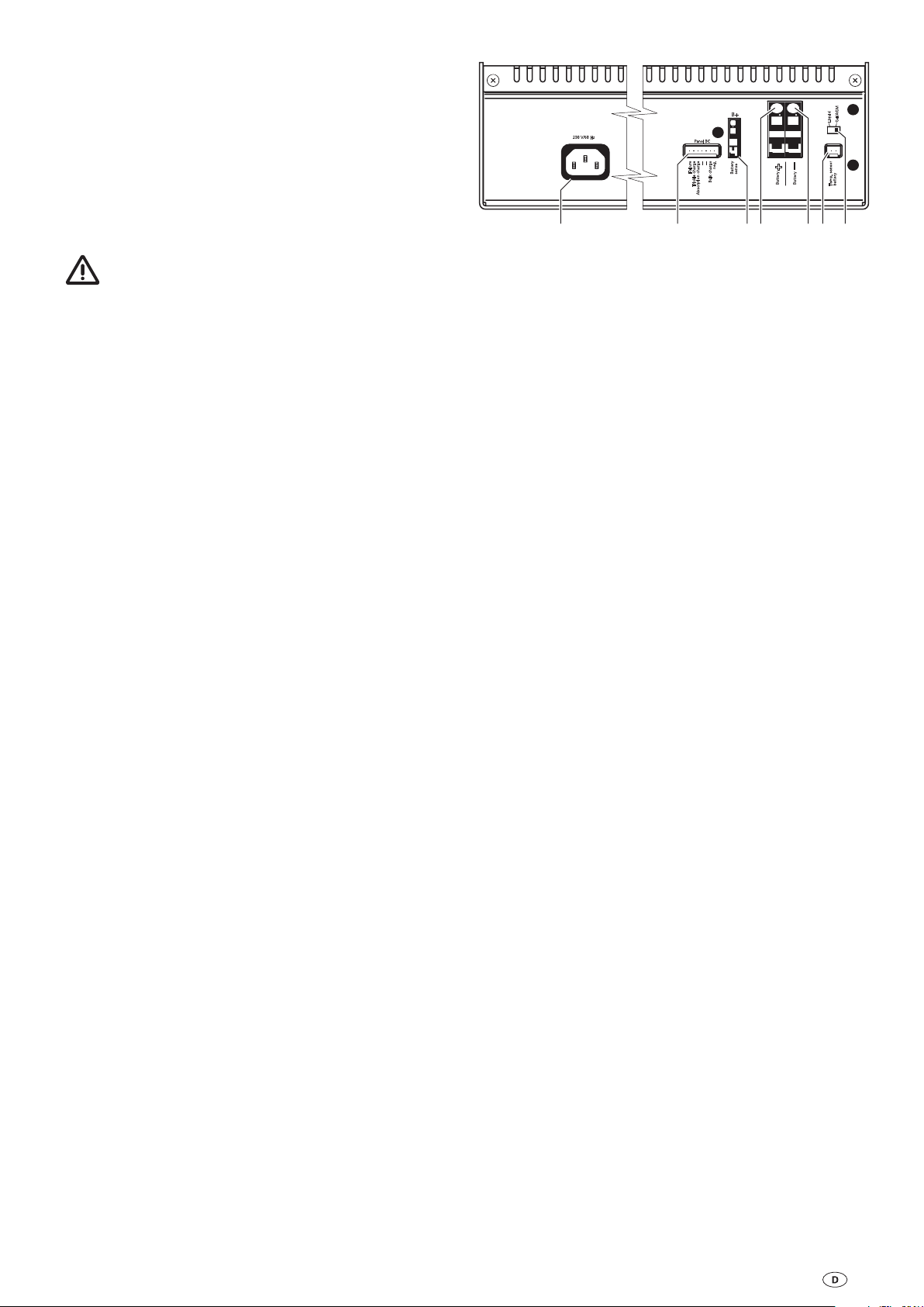
Ladekennlinie
HL = Hauptladephase
NL = Nachladephase
EL = Erhaltungsladung
Schaltautomatik (Hauptladevorgang)
AUS bei Batteriespannung 14,4 V, Ladestrom < 27 A
Schaltautomatik (Nachladephase)
10 Stunden konstant 14,4 V bei Gel-Batterien / AGM
4 Stunden konstant 14,4 V bei Flüssigelektrolytbatterien
Schaltautomatik (Erhaltungsladung)
Erhaltungsladung konstant 13,8 V
Temperaturabhängige Regelung (optional)
Die Werte der Schaltautomatik beziehen sich auf eine Batterietemperatur von 20 °C. Unter Verwendung des Temperaturfühlers an der Batterie variieren diese Werte in Abhängigkeit
von der Batterietemperatur.
Hohe Temperatur –> Absenkung der Schwellwerte
Niedere Temperatur –> höhergestellte Schwellwerte
Anwendung
Parallelbetrieb, allgemeiner Ladebetrieb
Temperatur
Umgebungstemperatur von -25 °C bis +35 °C
Bei Betrieb kann sich das Gehäuse auf ca. 75 °C erwärmen
Kühlung
Durch Konvektion
Ausführung
Gemäß den Bestimmungen des VDE und des
Gerätesicherheitsgesetzes
Bild 2: Ladekennlinie (prinzipieller Verlauf)
Technische Änderungen vorbehalten!
Fehlersuchanleitung
Fehler Behebung
Die Batterie wird nicht
geladen.
Der maximale Ladestrom
wird nicht erreicht.
Sollten diese Maßnahmen nicht zur Störungsbehe
bung führen, wenden Sie sich bitte an das Truma
Servicezentrum.
Prüfen Sie alle Anschlüsse
vom Ladeautomaten zur Batterie, achten Sie dabei auf
die richtige Polung. Stecken
Sie den Kaltgerätestecker am
Gerät aus und wieder ein.
Prüfen Sie die Sicherungen
und den Netzanschluss.
Das Gerät wird zu warm,
sorgen Sie für bessere Belüftung des Gerätes.
-
Verwendung
Zum Laden von Batterien mit 12 V Nennspannung und einer
Kapazität von 100 – 300 Ah
4
Zubehör
Truma Hersteller Garantieerklärung
Quickpower Polklemmen
Zum schnellen Verbinden
und Lösen von Batterieanschlüssen von Hand. Passend
für alle Anschlüsse nach DIN
und SAE
(Art.-Nr. C11000-02000).
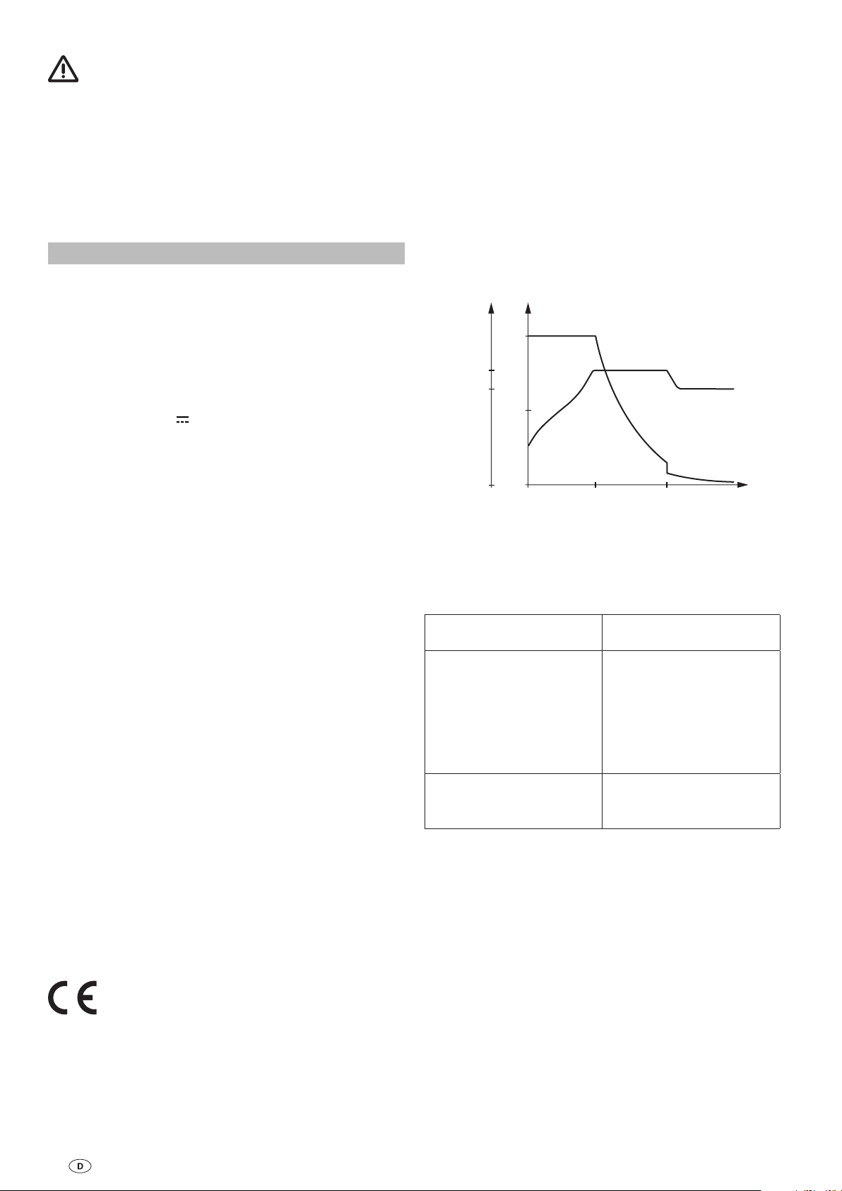
Temperaturfühler für Batterie
Ermöglicht eine für eine temperaturgeführte Batterieladung
Temperaturfühler mit
2 m Anschlusskabel und
Befestigungsmaterial
(Art.-Nr. C11000-00100).
Temperaturfühler mit
6 m Anschlusskabel und
Befestigungsmaterial
(Art.-Nr. C11000-00200).
Ladekontroll-Panel
Panel BC (430, 630, 860) zur Anzeige der Ladephasen, der
Parallelschaltung von Starter- und Versorgungsbatterie und
Störungen im Ladebetrieb in Verbindung mit dem Ladeautomaten BC 430 IU.
Panel BC (430, 630, 860) mit
7-poligem Steuerkabel 5 m
und Befestigungsschrauben
(Art.-Nr. 14300-03)
1. Garantiefall
Der Hersteller gewährt Garantie für Mängel des Gerätes, die
auf Material- oder Fertigungsfehler zurückzuführen sind. Daneben bestehen die gesetzlichen Gewährleistungsansprüche
gegen den Verkäufer fort.
Der Garantieanspruch besteht nicht
für Verschleißteile und bei natürlicher Abnutzung,
–
infolge Verwendung von anderen als Truma Originalteilen in
–
den Geräten,
infolge Nichteinhaltung der Truma Einbau- und
–
Gebrauchsanweisungen,
infolge unsachgemäßer Behandlung,
–
–
infolge unsachgemäßer, nicht von Truma veranlasster
Transportverpackung.
2. Umfang der Garantie
Die Garantie gilt für Mängel im Sinne von Ziffer 1, die innerhalb von 24 Monaten seit Abschluss des Kaufvertrages zwischen dem Verkäufer und dem Endverbraucher eintreten. Der
Hersteller wird solche Mängel durch Nacherfüllung beseitigen,
das heißt nach seiner Wahl durch Nachbesserung oder Ersatzlieferung. Leistet der Hersteller Garantie, beginnt die Garantiefrist hinsichtlich der reparierten oder ausgetauschten Teile
nicht von neuem, sondern die alte Frist läuft weiter. Weitergehende Ansprüche, insbesondere Schadensersatzansprüche
des Käufers oder Dritter sind ausgeschlossen. Die Vorschriften
des Produkthaftungsgesetzes bleiben unberührt.
Die Kosten der Inanspruchnahme des Truma Werkskundendienstes zur Beseitigung eines unter die Garantie fallenden
Mangels – insbesondere Transport-, Wege-, Arbeits- und
Materialkosten – trägt der Hersteller, soweit der Kundendienst
innerhalb von Deutschland eingesetzt wird. Kundendiensteinsätze in anderen Ländern sind nicht von der Garantie gedeckt.
Zusätzliche Kosten aufgrund erschwerter Aus- und Einbaubedingungen des Gerätes (z. B. Demontage von Möbel- oder
Karosserieteilen) können nicht als Garantieleistung anerkannt
werden.
3. Geltendmachung des Garantiefalles
Die Anschrift des Herstellers lautet:
Truma Gerätetechnik GmbH & Co. KG,
Wernher-von-Braun-Straße 12,
85640 Putzbrunn.
In Deutschland ist bei Störungen grundsätzlich das Truma
Servicezentrum zu benachrichtigen; in anderen Ländern
stehen die jeweiligen Servicepartner zur Verfügung (siehe
Truma Serviceheft oder www.truma.com). Beanstandungen
sind näher zu bezeichnen. Ferner ist die ordnungsgemäß ausgefüllte Garantie-Urkunde vorzulegen oder die Fabriknummer
des Gerätes sowie das Kaufdatum anzugeben.
Zur Vermeidung von Transportschäden darf das Gerät nur
nach Rücksprache mit dem Truma Servicezentrum Deutschland oder dem jeweiligen Servicepartner im Ausland versandt
werden. Andernfalls trägt das Risiko für evtl. entstehende
Transportschäden der Versender.
Im Garantiefall übernimmt das Werk die Kosten der Einsen
dung und Rücksendung. Liegt kein Garantiefall vor, gibt der
Hersteller dem Kunden Bescheid und nennt die vom Hersteller
nicht zu übernehmenden Reparaturkosten; in diesem Fall
gehen auch die Versandkosten zu Lasten des Kunden.
-
5
Einbauanweisung
Sicherheitshinweise
Das Gerät ist für den Betrieb in einer Umgebungstemperatur
bis 35 °C ausgelegt. Steigt die Geräteinnentemperatur durch
mangelnde Luftzirkulation oder zu hohe Umgebungstemperatur, so reduziert sich der Ladestrom automatisch stufenweise.
In diesem Gerät sind Bauteile eingebaut, die einen
Funken oder Lichtbogen erzeugen können!
Der Anschluss des Versorgungsnetzes an das Gerät muss in
Übereinstimmung mit den jeweils geltenden nationalen Installationsvorschriften vorgenommen werden.
Dieses Gerät beinhaltet Bauteile, die möglicherweise Lichtbögen und Funken erzeugen. Daher muss das Gerät, während
es in einer Garage oder einem ähnlichen Ort betrieben wird,
in einem für diesen Zweck vorgesehenen Raum oder Gehäuse
untergebracht werden!
Die Montage und der Anschluss von elektrischen Geräten
muss grundsätzlich durch geeignetes Fachpersonal erfolgen!
Stellen Sie sicher, dass die Stromzufuhr getrennt ist! Netzstecker ziehen!
Benutzen Sie zum Anschluss des Gerätes nur die mitgelieferten Teile sowie die vorgeschriebenen Leitungsquerschnitte
und Sicherungen!
Benutzen Sie nur geeignetes und einwandfreies Werkzeug.
Schließen Sie das Gerät nur gemäß des mitgelieferten Anschlussplanes an!
Aufstellen
Handhabung der Käfigzugfederklemmen
Bereiten Sie die Anschlusskabel vor. Das Kabelende für
den Anschluss B+ (kleine Käfigzugfederklemme) muss auf
8 – 9 mm abisoliert sein. Die Kabelenden für die Batterieanschlüsse (große Käfigzugfederklemmen) müssen auf
11 – 12 mm abisoliert sein. Aderendhülsen sind nicht
erforderlich.
Die Zugfederklemme kann mit Hilfe eines passenden Schlitzschraubendrehers geöffnet werden.
Führen Sie hierzu den Schlitzschraubendreher in die obere,
quadratische Öffnung ein und drücken Sie die Zugfederklemme
auf. Der Klemmteil der Feder in der oberen, runden Öffnung
schwenkt dabei auf.
Führen Sie das Kabel bis zur Isolierung in die Käfigzugfederklemme (obere, runde Öffnung) ein und ziehen Sie den
Schlitzschraubendreher heraus. Die Zugfederklemme schließt
sich wieder und das Kabel ist sicher geklemmt.
Wiederholen Sie den Vorgang für alle Anschlüsse:
B+, Battery +, Battery -
Achten Sie darauf, dass die Kabelenden fest in den Käfigzugfederklemmen sitzen!
Anschluss
Den im Umkarton befindlichen Beipack (Zubehör) entnehmen
und auf Vollständigkeit prüfen:
1 Gebrauchs- und Einbauanweisung
1 Anschlusskabel 230 V, 1 m
1 Maxisicherung 40 A mit Sicherungshalter
1 Flachstecksicherung 2 A mit Sicherungshalter
4 Befestigungsschrauben
4 Unterlegscheiben
2 Kabelschuhe
Das Gerät ist vor Feuchtigkeit und Nässe geschützt aufzustellen. Der Aufstellungsort muss sauber, trocken und gut belüftet
sein. Bei Betrieb kann sich das Gehäuse auf ca. 75 °C erwär
men. Halten sie daher einen Mindestabstand von 100 mm
ein und achten Sie darauf, dass die Lüftungsschlitze nicht
verdeckt werden.
Der für das Gerät bereitgestellte Raum darf nachfolgende Abmessungen nicht unterschreiten, da der Mindestabstand von
rundum 100 mm gewährleistet sein muss.
Länge: 502 mm / Breite: 373 mm / Höhe: 210 mm
Der Einbauraum für das Gerät muss oben und seitlich mit Lüftungsöffnungen versehen sein, die eine Gesamtöffnung von
100 cm² ergeben.
Flüssigelektrolytbatterien müssen in einer separaten Box mit
einer Entlüftung nach außen aufgestellt werden. Eine separate
Box ist bei Gel- und AGM-Batterien nicht notwendig. Die Installationsvorschriften des Batterieherstellers beachten.
Das Gerät mit den vier mitgelieferten Befestigungsschrauben
sicher befestigen. Die Füße des Gerätes können um 90° gedreht werden. Hierzu müssen die Schrauben an den Füßen
gelöst werden. Danach können die Füße gedreht und wieder
fest verschraubt werden.
Achten sie darauf, dass die Lüftungsschlitze frei bleiben!
Der Mindestabstand muss rundum 100 mm betragen!
Unzureichende Belüftung kann zur Überhitzung des Gerätes
führen!
-
Vor dem Anschließen oder Trennen von Leitungen sind
die Versorgungsleitungen von Batterie und Netz zu trennen! Nur vorgeschriebene Leitungsquerschnitte und Sicherungsstärken verwenden!
Leitungslängen und -querschnitte
Stromkreis Leitungs-
Plus
Ladestromleitung rot
Minus
Ladestromleitung blau
Messleitung B+ rot bis 10 m 0,75 mm²
Anschluss Batterie
Verbinden Sie das Ladegerät gemäß Anschlussplan (Bild 3)
mit der Batterie. Achten Sie auf die Leitungsquerschnitte und
den richtigen Anschluss der Pole!
–
Die Minus-Ladestromleitung für die Batterie (blau 10 mm²)
an den Minusausgang am Gerät und den Minuspol der Batterie anschließen.
Die Plus-Ladestromleitung für die Batterie (rot 10 mm²) an
–
den Plusausgang für Batterie am Gerät und den Pluspol der
Batterie anschließen. Diese Leitung ist unbedingt, nahe
dem Pluspol der Batterie, mit der mitgelieferten 40 A Maxi
sicherung abzusichern!
–
Messleitung (rot 0,75 mm²) an den B+ Eingang am Gerät
und den Pluspol der Batterie anschließen. Diese Leitung ist
unbedingt, nahe dem Pluspol der Batterie, mit der mitgelieferten 2 A Flachstecksicherung abzusichern!
Ladekontroll-Panel
Falls Sie ein Ladekontroll-Panel verwenden, stecken Sie dieses
am 7-poligen LK-Panelanschluss am Gerät an.
länge
bis 3 m
über 3 m
Leitungsquerschnitt
10 mm²
16 mm²
-
6
Temperaturfühler
Failure
Trickle charge
Absorption charge
--
--
Bulk charge
neg.
Battery
sense
Temp. sensor
battery
Liquid
Gel/AGM
Panel BC
_
Battery
B+
+
Battery
2A*
RT 0,75 mm²
2
1
RT 10 mm²
BL 10 mm²
40A*
Falls Sie einen Temperaturfühler für die Batterie verwenden,
kleben Sie den Temperaturfühler an die Stirnseite der Batterie.
Hierzu entfernen Sie die Schutzfolie am Klebepunkt des Temperaturfühlers und drücken ihn kräftig auf die gewünschte Position an der Batterie (siehe Beschreibung Temperaturfühler).
Stecken Sie das Kabel des Temperaturfühlers an den Temperaturfühleranschluss des Gerätes an (2-poliger Anschluss).
Inbetriebnahme
Der Ladeautomat ist in Betrieb sobald die Netzverbindung
hergestellt ist.
Vor dem Unterbrechen oder Schließen von Gleichstromverbindungen, z. B. Ladestromkabel an der Batterie, ist das Gerät
netzseitig abzuschalten. Netzstecker ziehen!
Umschalter Batterietyp
Stellen Sie den verwendeten Batterietyp (Flüssigelektrolyt
oder Gel / AGM) Ihrer Batterie am Umschalter ein.
Netzanschluss
Schließen Sie das Netzkabel an die Netzverteilung Ihres
Bootes, Reisemobiles oder Wohnwagens an. Grün / gelbe Lei
tung an Schutzerde!
Prüfen Sie alle Anschlüsse auf sicheren Sitz.
–
Stellen Sie als letztes die Netzverbindung über den Kaltgerä-
–
testecker 230 V des Netzkabels her.
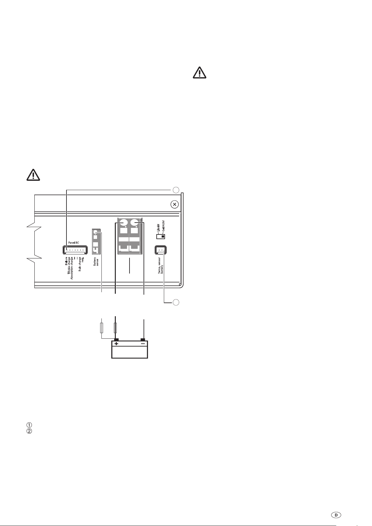
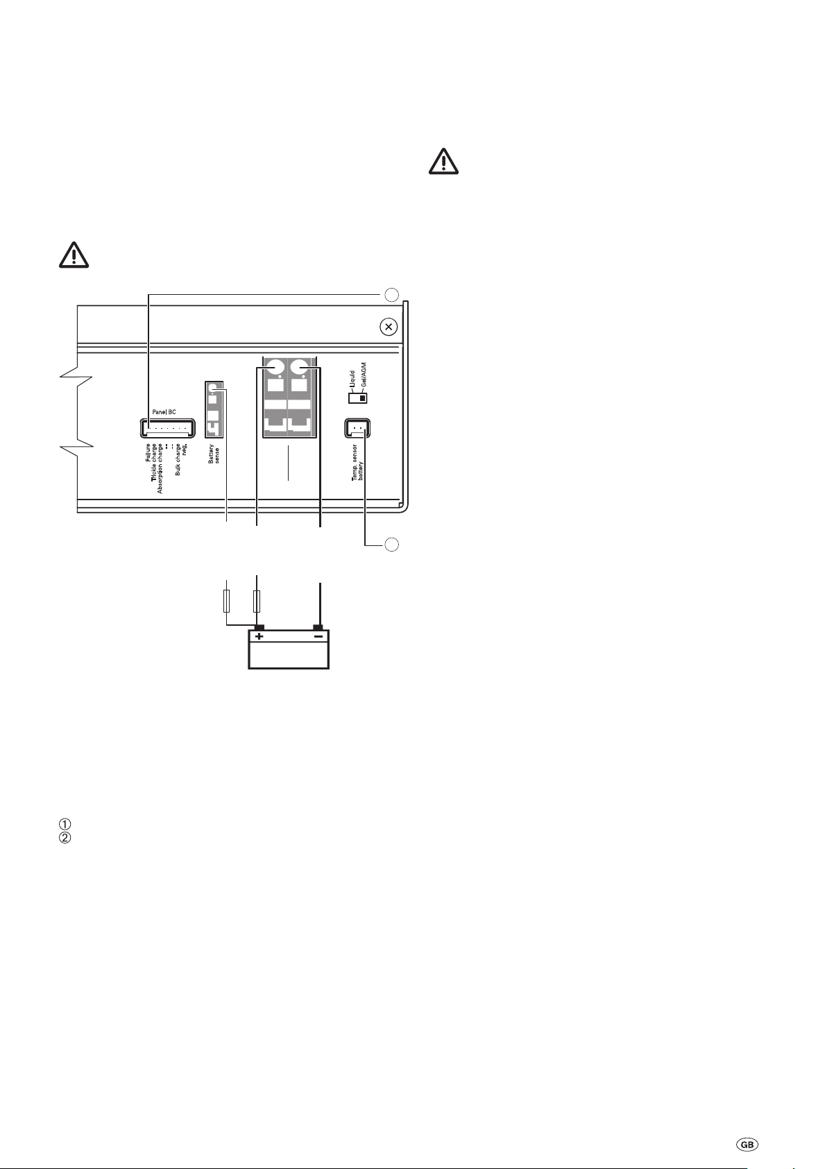
Anschlussplan
Sicherungen unbedingt nahe der Pluspole der Batterien
anbringen!
Batterien mit Zellenschluss dürfen nicht geladen werden.
Explosionsgefahr durch Knallgasentwicklung!
Voraussetzungen
Die Batterie muss eine Nennspannung von 12 V und eine
Mindestkapazität von 100 Ah haben. Batterien unter dieser
-
Mindestkapazität werden nur unzureichend geladen. Batterien
mit einer zu hohen Kapazität werden zu langsam geladen.
Ladevorgang
Das Laden der Batterie erfolgt automatisch. Nach zwischenzeitlichem Netzausfall wird automatisch der Hauptladevorgang
neu gestartet. Der Hauptladevorgang wird beendet, wenn die
Batteriespannung 14,4 V erreicht. Nach Ablauf der Nachla
dephase erfolgt die Umschaltung auf Erhaltungsladung von
konstant 13,8 V.
Parallelbetrieb
Bei Parallelbetrieb soll der Verbraucherstrom kleiner als der
maximale Ladestrom von 30 A sein. Nur so ist sichergestellt,
dass die Batterie aufgeladen wird, obwohl Verbraucher versorgt werden.
Netzbetrieb auf Fähren
Die Netzspannung auf Fähren kann starken Schwankungen
unterworfen sein. Verbinden Sie daher das Gerät nicht mit dieser Spannung.
-
Bild 3: Anschlussplan
* Sicherung im Lieferumfang enthalten. Die Sicherungen
dienen ausschließlich dem Leitungschutz.
Bei Leitungslängen über 3 m siehe „Leitungslängen und
-querschnitte“.
BL = blau
RT = rot
Ladekontroll-Panel (optional)
Temperaturfühler Batterie (optional)
Generatorbetrieb
Bitte beachten Sie die in der Betriebsanleitung des Herstellers
vorgegebene Handhabung. Der Generator muss die 230 V
Netzanschlusswerte einhalten. Schließen Sie das Gerät erst
dann an den Generator an, wenn dieser stabil läuft und trennen Sie das Gerät von diesem, bevor Sie ihn abschalten. Die in
der Anlauf- und Abstellphase entstehenden Spannungsspitzen
könnten das Gerät schädigen.
7

Automatic Charger BC 430 IU
Table of contents
Operating instructions
Glossary ................................................................................ 8
Symbols used ....................................................................... 8
Safety instructions
Intended use .......................................................................... 8
Improper use
Description .......................................................................... 9
Connections ........................................................................ 9
Charging process
Maintenance ....................................................................... 9
Disposal ................................................................................. 9
Technical Data
Dimensions / weight ........................................................... 10
Charging reference line
Troubleshooting ............................................................... 10
Accessories ....................................................................... 11
Manufacturer’s terms of warranty
Installation instruction
Safety instructions
Installation ......................................................................... 12
Handling the cage tension spring clamps
Connection ........................................................................ 12
Cable lengths and cross-sections ....................................... 12
Wiring diagram
Commissioning ................................................................. 13
Mains supply mode on ferries ............................................ 13
Generator mode .................................................................. 13
............................................................ 8
....................................................................... 9
............................................................... 9
.................................................................. 10
................................................... 10
................................ 11
s
.......................................................... 12
................... 12
................................................................. 13
Operating instructions
Please be sure to read the instructions for installation
and use before attempting to connect and use this
device!
Glossary
AGM-battery Lead acid battery, in which the elec-
trolyte is set in an absorbed glass mat.
Battery OPTIMA® YT S corresponds to an AGM-battery.
Symbols used
Symbol indicates a possible hazard.
Comment including information and tips.
Safety instructions
To protect you from electrical shocks, injury or burns
the following basic safety principles must be observed
when using electrical devices. Please read and follow these
instructions before using the device.
Installation
Ensure that the devices are positioned safely and cannot fall
down or over. Always position the cables to ensure they do
not pose a tripping hazard. Do not expose electrical devices to
rain. Do not operate electrical devices in damp or wet environments. Do not operate electrical devices close to flammable
liquids or gases. Position the devices so that they are out of
the reach of children.
Protection against an electrical shock
Only operate devices whose casings and cables are undamaged. Ensure the cables are installed safely. Do not pull on the
cables.
Only operate the device if it has been secured with
a 30 mA fault-current circuit breaker. Observe the
EVU-regulations.
Use
Do not use electrical devices for purposes other than those
stated by the manufacturer.
Repairs
Do not repair or modify the device. Please contact your dealer
or the Truma Service (see service manual or www.truma.com).
Accessories
Only use accessories and additional devices that are supplied
or recommended by the manufacturer.
Intended use
The automatic charger may only be used to charge 12 V lead
accumulators comprising 6 individual cells (e.g. car battery),
with a capacity of 100 – 300 Ah. It can be used universally and
is designed for continuous use or parallel mode. This automatic charger has been designed to work best with gel, AGM
or liquid electrolyte batteries. The automatic charger is particularly suitable for use in boats, campers and caravans. The
automatic charger may only be used in dry rooms.
8
Improper use
+
_
Failure
Trickle charge
Absorption charge
--
--
Bulk charge
neg.
Battery
sense
Temp. sensor
battery
Battery
Battery
Liquid
Gel/AGM
Panel BC
B+
230 V/50 Hz
1 2 3 754 6
Charging process
Do not use for 6 V batteries or non-chargeable
batteries!
The automatic charger may not be used to charge 6 V lead ac
cumulators. If batteries with a rated voltage of 6 V are charged
with the automatic charger, gassing occurs immediately
which creates an explosive detonating gas.
The automatic charger may not be used to charge nonchargeable batteries and / or nickel-cadmium batteries.
If the automatic charger is used to charge these batteries, the
case can burst explosively.
Description
The automatic charger contains state-of-the-art microprocessor-controlled charging technology. This technology allows
high performance whilst remaining lightweight and small.
Thanks to the top quality electronics, it works highly efficiently. The automatic charging process is gentle to the battery and
prevents damaging overcharging, which in turn significantly
extends the service life of the battery. After the battery and
mains supply have been connected, the automatic charger is
ready for use.
The automatic charger is designed for continuous operation
and parallel mode. Consumers can be continuously connected, switched on or disconnected. Consumers are supplied and
the battery charged at the same time. The consumer current
here should be smaller than the maximum charging current as
otherwise the battery will not charge.
Using a charging control panel, e.g. the Truma Panel BC (430,
630, 860), the individual charging phases of the battery can be
displayed. Also, any malfunctions of the automatic charger are
shown on the Truma Panel BC (430, 630, 860).
If the automatic charger is operated in conjunction with a
temperature sensor for the battery, the automatic charger
regulates the charging current automatically depending on the
operating temperature. This ensures particularly effective and
gentle charging of the battery. If a temperature sensor is not
used, the automatic charger regulates the charging process in
the same way as a battery temperature of 20 °C.
The device is designed for operation in an ambient temperature of up to 35 °C. If the temperature inside the device in
creases due to a lack of circulating air or due to the fact that
the ambient temperature is too high, the charging current is
automatically reduced gradually.
-
The automatic charger has an electronic reverse battery protection. The charging current is only released if the battery is
correctly connected and there is a minimum voltage of 1.5 V.
-
While it is being charged, the battery voltage is monitored
constantly by way of the B+ measuring line. The charging
process is carried out in accordance with the charging reference line with a minimum of performance loss. (Charging reference line, see figure 2).
Main charging phase
(all voltage values relate to a battery temperature of 20 °C)
Charging with maximum constant charging current until a battery voltage of approximately 14.4 V is reached. If in this range
of the main charging phase, the charging current falls below
90 % of the rated current due to internal battery resistance
and resistivity, the afterloading phase is started.
Afterloading phase
(all voltage values relate to a battery temperature of 20 °C)
The charging voltage is kept at a constant 14.4V for a period
of 10 hours for gel/AGM batteries or four hours for liquid
electrolyte batteries. At the end of this period, it changes to
the trickle current phase. If during this period, the current
increases to over 90 % of the rated current and if at the same
time the battery voltage drops to below 13.2 V for a period of
more than 15 minutes for liquid electrolyte batteries and more
than two hours for gel batteries and AGM, it switches back to
the main charging phase.
Trickle charging phase
(all voltage values relate to a battery temperature of 20 °C)
The charging voltage is set to 13.8 V. The charging current
drops to the equalizing charge value necessary for the battery. If due to the consumer, the charging current increases
to its rated value and if the battery voltage drops for at least
2 minutes below 13.2 V, the device switches back to the main
charging phase.
Parallel mode
If consumer current is used during the aftercharging phase or
the trickle charging phase, this is immediately recharged.
Maintenance
The power supply must always be disconnected before
performing any maintenance work on the device.
Clean the device and the ventilation slits with a dry and flufffree cloth.
Disposal
Connections
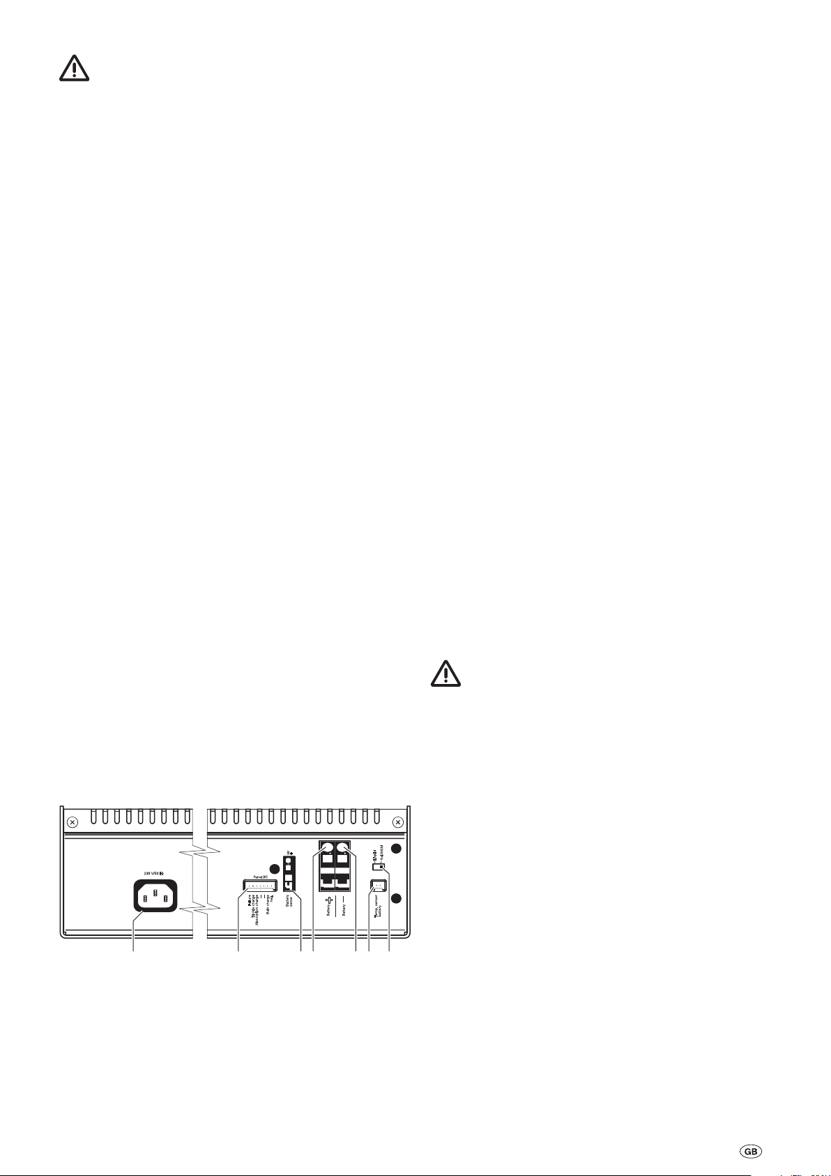
Fig. 1: Connections
1 Low heat device socket connection 230 V ~
2 Connection for charging control panel
3 Input B+ measuring line from the battery
4 Output + charging line battery
5 Output - charging line battery
6 Connection for temperature sensor
7 Changeover switch gel or AGM (OPTIMA® YT S) / liquid
electrolyte battery
The device must be disposed of in line with the administrative
regulations of the respective land in which it is used. National
regulations and laws must be observed.
9
Technical Data
13. 8
0
U[ V]
14. 4
0
50
100
I[%]
I
U
t[h]ELNLHL
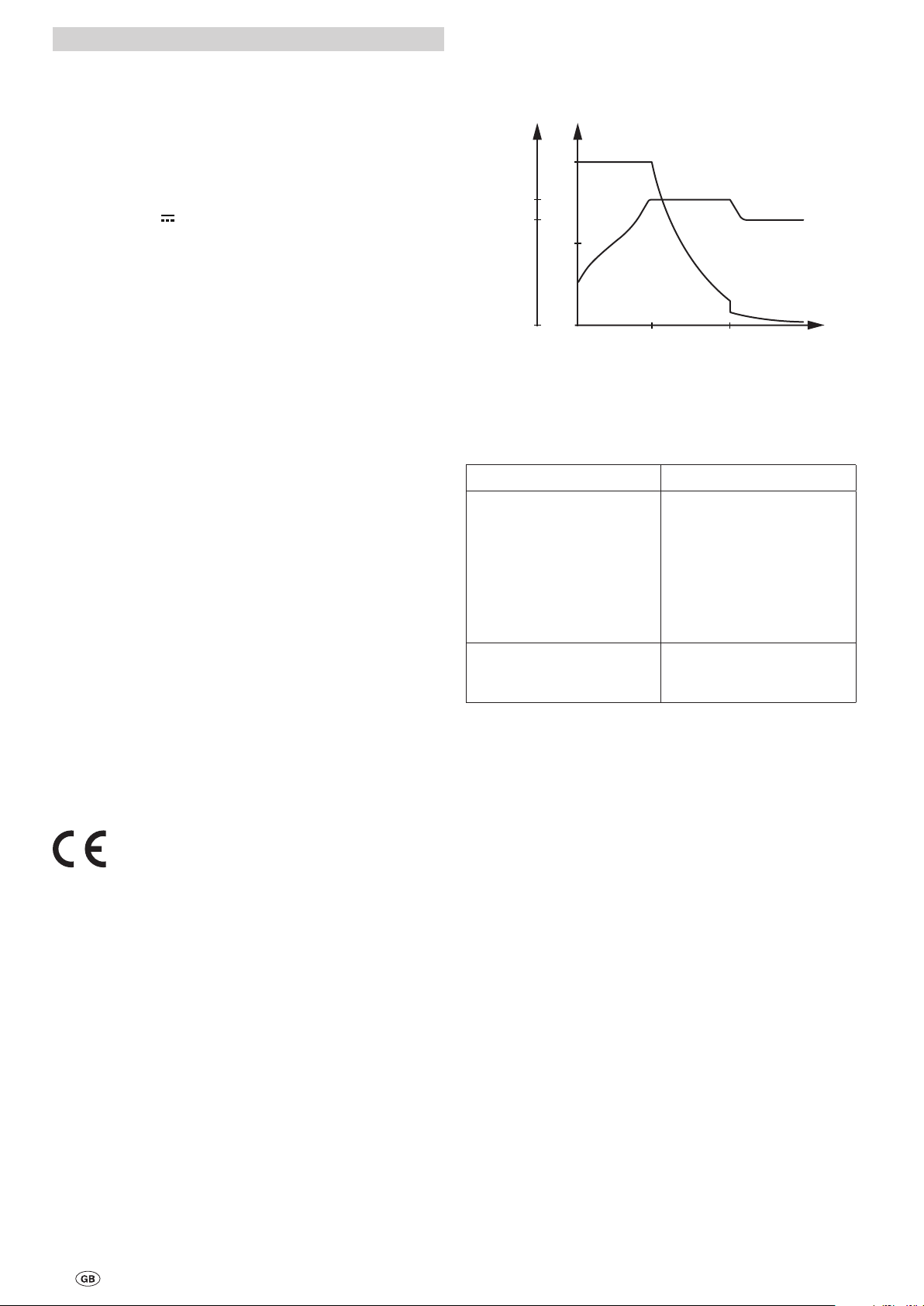
Charging reference line
Power supply
AC voltage 230 V / 50 Hz, single-phase
Range approx. 195 V – 250 V / 50 – 60 Hz
Output current (charging current battery)
Charging current max. 30 A, arithmetic mean value, electroni
cally controlled according to the IUoU charging reference line
Output voltage
DC voltage 12 V
Charging process
Automatic
Automatic switching (main charging process)
OFF at a battery voltage of 14.4 V, charging current < 27 A
Automatic switching (afterloading phase)
10 hours constant 14.4 V for gel batteries / AGM
4 hours constant 14.4 V for liquid electrolyte batteries
Automatic switching (trickle charging)
Trickle charging constant 13.8 V
Temperature-dependent control (optional)
The values of the automatic switching device refer to a battery
temperature of 20 °C. If a temperature sensor is used with the
battery, these values will vary in accordance with the battery
temperature.
High temperature –> reduction of the threshold values
Lower temperature –> higher threshold values
Application
Parallel mode, general charging mode
Temperature
Ambient temperature from -25 °C to +35 °C
During operation, the casing may heat up to around 75 °C
Cooling
By convection
HL = Main charging phase
NL = Afterloading phase
EL = Trickle charging
-
Fig. 2: Charging reference line (basic curve)
The right to effect technical modifications is reserved!
Troubleshooting
Error Rectification
The battery does not charge. Check all connections from
The maximum charging current is not reached.
the automatic charger to
the battery, ensure that they
are connected to the right
terminals. Unplug the cold
device plug on the device
then plug in again. Check all
fuses and the mains supply
connection.
The device is too warm, ensure better ventilation of the
device.
Configuration
In accordance with the VDE provisions and the device safety
law
Use
To charge the batteries with 12 V rated voltage and a capacity
of 100 – 300 Ah
Dimensions / weight
Casing
Aluminum, painted, ventilated
Length
302 mm (without feet)
Width
173 mm (without feet)
Height
100 mm
Weight
3 kg (30 N)
If these measures do not solve the problem, please con
tact the Truma Service Centre.
-
10

Accessories
Manufacturer’s terms of warranty
Quickpower terminal clamps
For fast manual connection
and release of the battery connections. Suitable for all DIN
and SAE connections
(part no. C11000-02000).
Temperature sensor for the battery
Allows temperature-controlled battery charging.
Temperature sensor with a
2 m connection cable and at
tachment material
(part no. C11000-00100).
Temperature sensor with a
6 m connection cable and
attachment material
(part no. C11000-00200).
Charging control panel
Panel BC (430, 630, 860) for displaying the charging phases,
the parallel switching from the starter and supply battery and
charging malfunctions in connection with the BC 430 IU automatic charger.
Panel BC (430, 630, 860) with
7-pin control cable 5 m and
attachment screws
(part no. 14300-03).
-
1. Case of warranty
The manufacturer grants a warranty for malfunctions in the
appliance which are based on material or production faults.
In addition to this, the statutory warranty claims against the
seller remain valid.
A claim under warranty shall not pertain:
for parts subject to wear and in cases of natural wear and
–
tear,
as a result of using parts that are not original Truma parts in
–
the units,
as a consequence of failure to respect Truma instructions
–
for installation and use,
as a consequence of improper handling,
–
as a consequence of improper transport packing, not
–
arranged by Truma.
2. Scope of warranty
The warranty is valid for malfunctions as stated under
item 1, which occur within 24 months after conclusion of
the purchase agreement between the seller and the final
consumer. The manufacturers will make good such defects
by subsequent fulfilment, i.e. at their discretion either by
repair or replacement. In the event of manufacturers providing service under warranty, the term of the warranty shall not
recommence anew with regard to the repaired or replaced
parts; rather, the old warranty period shall continue to run.
More extensive claims, in particular claims for compensatory
damages by purchasers or third parties, shall be excluded.
This does not affect the rules of the product liability law.
The manufacturer shall bear the cost of employing the Truma
customer service for the removal of a malfunction under warranty – in particular transportation costs, travelling expenses,
job and material costs, as long as the service is carried out in
Germany. The warranty does not cover customer service work
in other countries.
Additional costs based on complicated removal and installation conditions of the appliance (e.g. removal of furniture or
parts of the vehicle body) do not come under warranty.
3. Raising the case of warranty
The manufacturer's address is:
Truma Gerätetechnik GmbH & Co. KG,
Wernher-von-Braun Strasse 12,
85640 Putzbrunn.
In Germany, always notify the Truma Service Centre if problems are encountered; in other countries the relevant service
partners should be contacted (see Truma Service Booklet
or www.truma.com). Any complaints are to be described in
detail. In addition, the properly completed guarantee certifi
cate is to be presented, or the factory number of the unit and
the date of purchase given.
To avoid transport damage, the device may only be dispatched
after agreement with the Truma Service Centre in Germany or
with the particular service partner concerned abroad. The risk
for possible transport damage will otherwise be borne by the
consignor.
-
If it is a case of warranty, the factory shall bear the cost for
the delivery to the factory and the cost for returning the appliance to the customer. If the damage is deemed not to be
a warranty case, the manufacturer shall notify the customer
and shall specify repair costs which shall not be borne by the
manufacturer; in this case, the customer shall also bear the
shipping costs.
11
Installation instructions
Safety instructions
This device contains parts that could cause sparks or a
light arc!
Handling the cage tension spring clamps
Prepare the connection cables. Remove 8 – 9 mm of the insulation sheath on the end of the cable for the B+ connection
(small cage tension spring clamp). Remove 11 – 12 mm of
the insulation sheath on the end of the cable for the battery
connections (large cage tension spring clamps). Cable end
sleeves are not required.
The device must be connected to the mains power supply
in accordance with the respective valid national installation
regulations.
This device contains parts that could cause sparks or a light
arc. Therefore if the device is operated in a garage or a similar
place, it must be placed in a suitable casing or room appropriate for this purpose!
Only qualified technicians may assemble and connect electrical devices!
Ensure that the power supply has been disconnected! Disconnect the mains plug!
Only use the supplied parts and the specified cable cross-sections and fuses to connect the device!
Only use suitable and fully functional tools.
Only wire the device as specified in the supplied wiring
diagram!
Installation
Remove the equipment pack (accessories) and check it is
complete:
1 instructions for installation and use
1 connection cable 230 V, 1 m
1 Maxi fuse 40 A with fuse holder
1 flat pin fuse 2 A with fuse holder
4 mounting screws
4 washers
2 cable shoes
The device should be installed away from damp and wet. The
installation site should be clean, dry and well ventilated. During operation, the casing can heat up to around 75 °C. There
fore observe a minimum clearance of 100 mm and ensure that
the ventilation slits are not covered.
The designated room in which the device is to be installed
may not undercut the following dimensions as a minimum
clearance of 100 mm all-round must be observed.
Length: 502 mm / Width: 373 mm / Height: 210 mm
The installation space for the device must have ventilation
openings at the top and side that provide a total opening surface of 100 cm².
Liquid electrolyte batteries need to be placed in a separate
box with ventilation directed to the outside. The gel and AGM
batteries do not need a separate box. Observe the installation
regulations of the battery manufacturer.
Securely attach the device using the 4 supplied mounting
screws. The device‘s feet can be turned by 90°. To do this,
loosen the screws on the feet, then the feet can be turned and
screwed tight again.
Ensure that the ventilation slits remain free! There
should be a minimum clearance of 100 mm all round!
Inadequate ventilation can cause the device to overheat!
The device is designed for operation in an ambient temperature of up to 35 °C. If the temperature inside the device in
creases due to a lack of circulating air or due to the fact that
the ambient temperature is too high, the charging current is
automatically reduced gradually.
-
-
The spring terminal can be opened up with the aid of a suitable slit screwdriver.
Insert the tip of the screwdriver into the upper, square opening, and push on the spring terminal. The spring terminal in
the lower, round opening opens up.
Insert the cable into the cage tension spring clamp as far as
the insulation (upper, round opening) and remove the screwdriver. The spring clamp will close again and the cable is secured tightly.
Repeat this procedure for all connections:
B+, Battery +, Battery -
Ensure that the cable ends are securely clamped into the cage
tension spring clamps!
Connection
Before connecting or disconnecting the cables, the
supply lines to the battery and mains supply must be
disconnected! Only use the specified cable cross-sections and
fuses of the correct strength!
Cable lengths and cross-sections
Power circuit
Plus
Charger cable red
Minus
Charger cable blue
B+ measuring line red up to 10 m 0.75 mm²
Battery connection
Connect the charger to the battery as shown in the diagram
(ill. 3). Check that the correct cable cross-sections are used
and that the terminals are connected correctly!
Connect the negative charger cable (blue 10mm²) of the
–
battery to the negative terminal of the charger and the negative terminal of the battery.
Connect the positive charger cable (red 10mm²) for the bat-
–
tery to the positive terminal of the charger for the battery
and the positive terminal of the battery. It is imperative that
this cable is secured with the supplied 40 A Maxi fuse close
to the positive terminal!
–
Connect the measuring cable (red 0.75 mm²) to the B+ in
put on the device and the positive terminal of the battery. It
is imperative that this cable is secured with the supplied
2 A flat pin fuse close to the positive terminal!
Charging control panel
If you use a charging control panel, connect this to the 7-pin
LK panel connection on the device.
Temperature sensor
If you use a temperature sensor for the battery, adhere the
temperature sensor to the face side of the battery. To do this,
remove the protective film from the self-adhesive point of the
temperature sensor and press it firmly onto the desired position of the battery (see Temperature sensor description). Connect the cable from the temperature sensor to the temperature sensor connection of the device (2-pin connection).
Cable
length
up to 3 m
over 3 m
Cable
cross-section
10 mm²
16 mm²
-
12
Battery type changeover switch
Failure
Trickle charge
Absorption charge
--
--
Bulk charge
neg.
Battery
sense
Temp. sensor
battery
Liquid
Gel/AGM
Panel BC
_
Battery
B+
+
Battery
2A*
RT 0.75 mm²
2
1
RT 10 mm²
BL 10 mm²
40A*
Set the battery type (liquid electrolyte or Gel / AGM) of your
battery on the battery switchover.
Main supply connection
Connect the main power cable of your boat, camper or caravan. Green / yellow cable to the protective earth!
Check all connections are tight.
–
–
Finally, connect to the mains using the 230 V cold device
plug of the power cable.
Commissioning
The automatic charger is operational as soon as it is connected to the mains supply.
Before disconnecting or interrupting the DC voltage connections, e. g. the charging cable to the battery, the device needs
to be switched off at the mains. Disconnect the mains plug!
Batteries with short circuits may not be charged. There
is a risk of explosion caused by the generated detonat-
ing gas!
Wiring diagram
Always install the fuses close to the positive terminal of
the battery!
Prerequisites
The battery must have a rated voltage of 12 V and a minimum
capacity of 100 Ah. Batteries below this minimum capacity
will not be adequately charged. Batteries with capacities that
are too high will be charged too slowly.
Charging process
The battery is charged automatically. After any mains power
failures, the main charging process is automatically restarted.
The main charging process is stopped when the battery
voltage has reached 14.4 V. At the end of the aftercharging
phase, the charging process switches to trickle charging at a
constant 13.8 V.
Parallel operation
In parallel operation, the current drawn up by electrical equipment should be less than the maximum charging current of
30 A. This is the only way to ensure that the battery is being
charged even though consumers are being supplied.
Mains supply mode on ferries
The main supply voltage on ferries can be prone to heavy fluctuations. Therefore do not connect the device to this voltage.
Generator mode
Please observe the handling instructions in the manufacturer‘s
operating instructions. The generator must satisfy the 230 V
mains power connection values. Only connect the device to
the generator if this runs stably and disconnect the device
from this before you turn it off. The voltage peaks generated in
the start-up and shutdown phases can damage the device.
Fig. 3: Wiring diagram
* Fuse included in the delivery. The fuses only serve to protect
the cables.
For cables longer than 3 m, see “Cable lengths and
cross-sections”.
BL = blue
RT = red
Charging control panel (optional)
Temperature sensor of the battery (optional)
13

Chargeur BC 430 IU
Table des matières
Mode d‘emploi
Glossaire .............................................................................. 14
Symboles utilisés ................................................................ 14
Consignes de sécurité
Utilisation ............................................................................ 15
Utilisation non conforme
Description ........................................................................ 15
Raccordements ................................................................ 15
Recharge ............................................................................ 15
Entretien ............................................................................ 16
Élimination ........................................................................... 16
Caractéristiques techniques
Dimensions / poids .............................................................. 16
Courbe caractéristique de charge
Diagnostic des dérangements
Accessoires ....................................................................... 17
Déclaration de garantie du fabricant
Instructions de montag
Consignes de sécurité
Installation ......................................................................... 18
Utilisation des borniers débrochables
Branchement ..................................................................... 18
Longueurs et diamètres des câbles .................................... 18
Schéma de câblage
Mise en service
Fonctionnement sur réseau sur des ferrys ......................... 19
Fonctionnement sur générateur ......................................... 19
..................................................... 14
................................................ 15
.......................................... 16
................................. 16
....................................... 16
............................ 17
e
..................................................... 18
.......................... 18
.......................................................... 19
................................................................ 19
Mode d‘emploi
Veuillez impérativement lire les instructions de montage
et d’utilisation avant de brancher et de mettre en ser
vice l’appareil !
-
Glossaire
Batterie AGM Batterie au plomb-acide, dans
Batterie OPTIMA® YT S correspond à une batterie AGM.
laquelle l‘électrolyte se trouve dans
un mat de microfibres de verre
(absorbed glass mat).
Symboles utilisés
Ce symbole indique des risques possibles.
Informations et conseils.
Consignes de sécurité
Lors de l‘utilisation d‘appareils électriques, les consi-
gnes de sécurité de base suivantes doivent être respectées afin d‘éviter tout risque d‘électrocution, de blessure
et d‘incendie. Veuillez lire et respecter ces consignes avant
d‘utiliser l‘appareil.
Installation
Veillez à ce que les appareils soient installés de manière sûre
et ne puissent pas tomber ou se renverser. Posez toujours les
câbles de manière à éviter tout risque de trébuchement. N‘exposez pas les appareils électriques à la pluie. N‘utilisez pas
les appareils électriques dans un environnement humide ou
mouillé. N‘utilisez pas les appareils électriques à proximité de
liquides ou de gaz inflammables. Installez vos appareils électriques hors de portée des enfants.
Protection contre les risques d‘électrocution
Utilisez uniquement des appareils dont le boîtier et les câbles
sont en parfait état. Veillez à ce que les câbles soient correctement posés. Ne tirez pas sur les câbles.
Sécurisez et utilisez uniquement l‘appareil en le bran-
chant à un interrupteur de protection contre les courants de court-circuit avec 30 mA de courant nominal de
court-circuit. Respectez les directives de votre société de
distribution d‘électricité.
Utilisation
N‘utilisez pas les appareils électriques à d‘autres fins que celles indiquées par le fabricant.
Réparation
N‘effectuez aucune réparation ou modification sur l‘appareil.
Contactez votre revendeur ou le service Truma (voir carnet
d‘entretien ou www.truma.com).
Accessoires
Utilisez uniquement des accessoires fournis ou recommandés
par le fabricant.
14

Utilisation
+
_
Failure
Trickle charge
Absorption charge
--
--
Bulk charge
neg.
Battery
sense
Temp. sensor
battery
Battery
Battery
Liquid
Gel/AGM
Panel BC
B+
230 V/50 Hz
1 2 3 754 6
Le chargeur automatique sert exclusivement à recharger
les accumulateurs au plomb de 12 V composés de 6 batteries (par ex. batterie de voiture) avec une capacité de
100 – 300 Ah. Il est utilisable de manière universelle et conçu
pour un fonctionnement en continu et en parallèle. Le chargeur automatique sera de préférence utilisé pour des batteries
au gel, AGM et à électrolyte liquide. Le chargeur automatique
convient particulièrement pour les bateaux, les mobile homes
et les caravanes. Le chargeur automatique peut uniquement
être utilisé dans un environnement sec.
Raccordements
Utilisation non conforme
Ne pas utiliser pour des batteries de 6 V ou des batteries non rechargeables !
Le chargeur automatique ne peut être utilisé pour recharger
des accumulateurs au plomb de 6 V. Lorsque des batteries
avec une tension nominale de 6 V sont rechargées avec le
chargeur automatique, le dégagement gazeux est immédiat.
Un gaz détonant se forme.
Le chargeur automatique ne peut pas être utilisé pour recharger des batteries non rechargeables et / ou des batteries au
nickel-cadmium.
Lors de la recharge de ce type de batteries avec le chargeur
automatique, l‘enveloppe peut éclater en explosant.
Description
Le chargeur automatique est un produit intégrant une technologie de recharge ultramoderne commandée par microprocesseurs. Cette technologie permet une puissance élevée
avec un poids réduit et de faibles dimensions. L‘utilisation de
pièces électroniques de qualité supérieure permet au chargeur
automatique de fonctionner avec une grande efficacité. La
recharge automatique s‘effectue en douceur sans surcharge
dommageable pour la batterie. La durée de vie de la batterie
est ainsi sensiblement allongée. Une fois la batterie branchée
et la connexion au réseau établie, le chargeur automatique est
prêt à fonctionner.
Le chargeur automatique a été conçu pour le fonctionnement
en continu et en parallèle. Les appareils électriques peuvent
rester constamment branchés, être connectés ou déconnectés. Les appareils sont alimentés en courant et la batterie est
rechargée dans le même temps. Le courant des appareils
électriques doit cependant être inférieur au courant de charge
max. Dans le cas contraire, la batterie ne sera pas rechargée.
L‘utilisation d‘un tableau de contrôle de la charge, par ex. le
Panel BC de Truma (430, 630, 860) permet d‘afficher les différentes phases de charge de la batterie. Les éventuels dérangements du chargeur automatique sont également indiqués par
le Panel BC (430, 630, 860) de Truma.
Lorsque le chargeur automatique est utilisé avec un capteur
de température pour la batterie, le chargeur automatique règle
automatiquement la tension de charge en fonction de la température de la batterie. Cela permet une recharge particulièrement efficace et douce de la batterie. Sans capteur de température, le chargeur automatique règle la recharge comme pour
une température de batterie de 20 °C.
L‘appareil est conçu pour être utilisé avec une température
ambiante de max. 35 °C. Si la température à l‘intérieur de l‘appareil augmente en raison du manque de circulation d‘air ou
d‘une température ambiante trop élevée, le courant de charge
diminue automatiquement graduellement.
Fig. 1 : Raccordements
1 Prise de raccordement de sécurité 230 V ~
2 Raccordement pour le tableau de contrôle de charge
3 Entrée fil de test B+ de la batterie
4 Sortie + câble de recharge batterie
5 Sortie - câble de recharge batterie
6 Raccordement pour capteur de température
7 Commutateur batterie au gel ou AGM (OPTIMA® YT S) /
à électrolyte liquide
Recharge
Le chargeur automatique est équipé d‘une protection électronique contre l‘inversion de polarité. Le courant de charge
est uniquement généré lorsque la batterie est correctement
branchée et avec une tension minimum de 1,5 V. Durant la recharge, la tension de la batterie est constamment contrôlée à
l’aide du fil de test B+. La recharge s‘effectue conformément
à la courbe caractéristique de charge avec une perte de puissance minimale (courbe caractéristique de charge voir fig. 2).
Phase de charge principale
(toutes les valeurs de tension sont valables pour une température de batterie de 20 °C)
Recharge avec courant de charge maximum jusqu‘à ce que la
tension de batterie de 14,4 V soit atteinte. Si durant la phase
de charge principale le courant de charge passe en dessous
de 90 % du courant nominal à cause de la résistance interne
de la batterie et des résistances de câbles, la phase de postcharge est lancée.
Phase de post-charge
(toutes les valeurs de tension sont valables pour une température de batterie de 20 °C)
La tension de charge est maintenue à une valeur constante de
14,4 V pendant dix heures pour les batteries au gel /AGM et
pendant quatre heures pour les batteries à électrolyte liquide.
Une fois ce temps écoulé, le chargeur bascule en phase de
charge de maintien. Si durant cette phase, le courant dépasse
90 % du courant nominal et que la tension de la batterie passe
en dessous de 13,2 V durant plus de 15 minutes pour les bat
teries à électrolyte liquide et durant plus de deux heures pour
les batteries au gel et AGM, le chargeur rebascule en phase
de charge principale.
Phase de charge de maintien
(toutes les valeurs de tension sont valables pour une température de batterie de 20 °C)
La tension de charge est réglée sur 13,8 V. Le courant de
charge est réduit pour atteindre la valeur nécessaire pour
la charge de compensation de la batterie. Si le courant de
charge atteint sa valeur nominale à cause des appareils électriques et que la tension de la batterie passe en dessous de
13,2 V durant au moins deux minutes, le chargeur rebascule
en phase de charge principale.
Fonctionnement en parallèle
Si les appareils électriques utilisent du courant durant la phase
de post-charge ou la phase de charge de maintien, celui-ci est
immédiatement rechargé.
-
15
Entretien
13. 8
0
U[ V]
14. 4
0
50
100
I[%]
I
U
t[h]ELNLHL
Dimensions / poids
Coupez impérativement l‘alimentation électrique de
l‘appareil avant tout travail d‘entretien.
Nettoyez l‘appareil et les fentes d‘aération à l‘aide d‘un chiffon
sec sans peluches.
Élimination
L‘appareil doit être éliminé conformément aux règles administratives du pays d‘utilisation. Les directives et les lois nationales doivent être respectées.
Caractéristiques techniques
Alimentation électrique
Courant alternatif 230 V / 50 Hz, monophasé
Plage 195 V – 250 V / 50 – 60 Hz
Courant de sortie (courant de charge batterie)
Courant de charge max. 30 A, valeur moyenne arithmétique,
réglé électroniquement selon la courbe caractéristique de
charge IUoU
Tension de sortie
Courant continu 12 V
Recharge
Automatique
Boîtier
Aluminium, laqué, aéré
Longueur
302 mm (sans les pieds)
Largeur
173 mm (sans les pieds)
Hauteur
100 mm
Poids
3 kg (30 N)
Courbe caractéristique de charge
HL = Phase de charge principale
NL = Phase de post-charge
EL = Charge de maintien
Commutation automatique (phase de charge principale)
ARRÊT avec tension de batterie14,4 V, courant de charge < 27 A
Commutation automatique (phase de post-charge)
10 heures constant 14,4 V pour batteries au gel / AGM
4 heures constant 14,4 V pour batteries à électrolyte liquide
Commutation automatique (charge de maintien)
Charge de maintien constante 13,8 V
Réglage dépendant la température (en option)
Les valeurs de la commutation automatique se réfèrent à
une température de batterie de 20 °C. En cas d’utilisation du
capteur de température sur la batterie, ces valeurs varient en
fonction de la température de la batterie.
Température élevée –> diminution des valeurs seuils
Température basse –> augmentation des valeurs seuils
Application
Fonctionnement en parallèle, mode de recharge général
Température
Température ambiante de -25 °C à +35 °C
Pendant le fonctionnement, le boîtier peut atteindre une température de 75 °C
Refroidissement
Par convection
Modèle
Conforme aux directives du VDE et de la loi sur la sécurité des
appareils
Fig. 2 : Courbe caractéristique (tracé théorique)
Sous réserve de modifications techniques !
Diagnostic des dérangements
Dérangement Solution
La batterie ne se recharge
pas.
Le courant de charge max.
n‘est pas atteint.
Si ces mesures ne permettent pas de remédier au déran
gement, veuillez contacter le centre de service Truma.
Vérifiez tous les raccordements du chargeur automatique vers la batterie et veillez
à la bonne polarité. Retirez et
rebranchez la fiche de sécurité à l‘appareil. Vérifiez les
fusibles et le branchement
au réseau.
L‘appareil chauffe trop,
veillez à améliorer la ventilation de l‘appareil.
-
Utilisation
Recharge de batteries d‘une tension nominale de 12 V et
d‘une capacité de 100 – 300 Ah
16
 Loading...