

Page 1
Service (New Zealand)
Telephone: (04) 232 38 98
Facsimile: (04) 232 38 78
Service (Australia)
Telephone: (03) 95 45 56 55
Facsimile: (03) 95 45 59 66
Dometic Pty Ltd
6 Treforest Drive,
Clayton, Victoria 3168
Australia
Leisure Appliances NZ Ltd
26 Cashew Street, Grenada
North, Wellington
New Zealand
Operating instructions Page 3
Installation instructions Page 6
To be kept in the vehicle!
Boiler
60°
70°
Boiler EL
230 V ~
Boiler
L. P. Gas and 230/240 V
Electric Storage Water Heater
Model B 10 / B 14
from 11/2003
Page 2
2
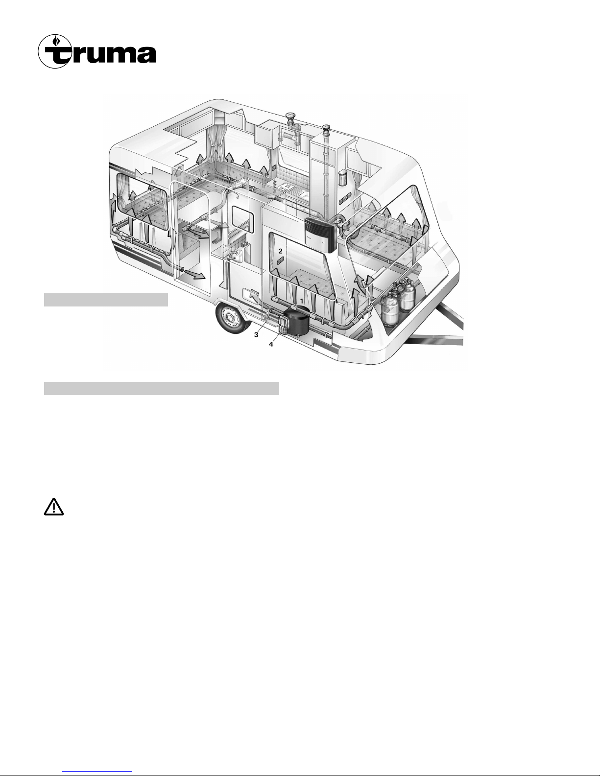
Installation example
1 Truma-Boiler
2 Control panel
3 Safety/drain valve
4 Cowl for combustion air intake
and exhaust gas discharge
General safety notes
In event of leaks in the gas system or if there is a smell of gas:
– extinguish all naked flames
– do not smoke
– switch off all appliances
– shut off the gas cylinder
– open the windows and doors
– do not actuate any electrical switches
– have the entire system checked by an expert!
Repairs may only be carried out by an expert.
Danger: Failure to operate the relief valve easing gear at least
once every six months may result in the water heater splitting.
Continuous leakage of water from the valve may indicate a
problem with the water heater!
– Water may drip from the discharge pipe of the pres sure relief
device and this pipe must be left open to the atmosphere.
– The pres sure relief device is to be operated regularly to
remove lime deposits and to verify that it is not blocked.
– Any discharge pipe connected to the safety (pres sure relief)
valve is to be installed in a continuously downward direction
and in a frost free ambient.
– This unit is not to be used by children or infirm persons
without proper supervision at all times. Not to be used as a
toy.
– Before gaining access to any and all terminals, please ensure
all supply circuits are disconnected (i.e. 230 – 240 V and
12 V) and gas supply is securely turned off.
– Any work involving connection or interconnecting wiring
must be conducted by a licensed electrician.
– Any alteration to the appliance (including cowl) or the use
of spare parts and accessories which are important for the
functioning of the heater and which are not original Truma
parts, as well as the non-observance of the installation and
operating instructions, shall lead to the cancelling of the
guarantee and exclusion of liability claims. It also becomes
illegal to use the appliance, and in some countries this even
makes it illegal to use the vehicle.
– The operating pressure for the gas supply is 2.75 kPa
(propane) and must correspond to the operating pressure
of the appliance (see data plate).
– LPG Systems and pressure regulators must comply with
the technical and administrative regulations of the country
in which the appliance is used. For your own safety it is
absolutely necessary to have the complete gas installation
regularly checked by an expert (at least every 2 years).
The vehicle owner is always responsible for arranging
the gas inspection.
– Do not operate when travelling.
– Do not operate the water heater when refuelling the vehicle
and when in the garage.
– Items sensitive to heat (e.g. spray cans) must not be stored
in the installation area, since excess temperatures may under
circumstances be incurred there.
– During the initial operation of a brand new appliance (or
after it has not been used for some time), a slight amount of
fumes and a slight smell may be noticed for a short while.
Remedial action here is to immediately run the heater and to
ensure adequate room ventilation.
– If the burner makes an unusual noise or if the flame lifts off,
it is likely that the gas pressure regulator is faulty and it is
essential to have it checked.
Boiler B 10 / B 14
Liquid gas storage water heater
(Special version BN 10 / BN 14
with additional electric heating 230 V, 850 W)
Page 3
3
Operating instructions
Always observe the operating instructions prior to
starting! The vehicle owner is responsible for the correct
operation of the appliance.
The installer or vehicle owner must apply the yellow sticker
with the warning information, which is enclosed with the appliance, to a place in the vehicle where it is clearly visible to
all users (e.g. on the wardrobe door)! Ask Truma to send you
stickers, if necessary.
Before using the first time, it is essential to flush the
entire water supply through with clean warm water.
Always mount the cowl cap when the water heater is not
being operated! Drain the water heater if there is a risk of frost!
There shall be no claims under guarantee for damage
caused by frost!
Always remove the cowl cover prior to operating the
water heater!
If connecting to a central water supply (rural or city connection) or when using more powerful pumps, a pressure reducer
must be used which prevents pressures of greater than 400 kPa
occurring in the Boiler.
Filling the Truma-Boiler with water
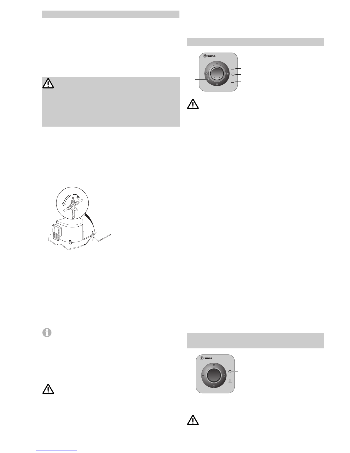
1. Check that the drain valve in the cold water intake is closed:
Lever should be in horizontal position, position (e).
f
e
e
e = Lever position
„Closed“
f = Lever position
„Drain“
2. Open hot tap in bathroom or kitchen, with pre-selecting
mixing taps or single-lever fittings set to „hot“.
3. Switch on power for water pump (main switch or pump
switch).
Leave the tap open to let air escape while the water heater is
filling. The heater is filled when water flows out of the tap.
Residues of frozen water can prevent filling if there is a frost.
The water heater can be defrosted by switching on the heater
for a short period (max. 2 minutes). Frozen pipes can be
defrosted by heating the room.
If just the cold water system is being used, without water
heater, the heater tank is also filled up with water. In order to avoid damage through frost, the water contents must be
drained by actuating the drain valve, also when the heater has
not been used. As an alternative, two shut-off valves, resistant
to hot water, can be fitted in front of the cold and hot water
connection.
Draining the water heater
If the mobile home is not used during periods of frost,
it is essential that the Boiler be emptied.
1. Disconnect power for water pump (main switch or pump
switch).
2. Open hot water taps in bathroom and kitchen.
3. Open safety/drain valve: Lever in vertical position, position (f).
4. The water heater is now drained directly to the outside via
the drain valve. Check that the water contents have been
completely drained (10 litres or 14 litres).
Switching on gas operation
Boiler
60°
70°
b
b
a
c
a = Red indicator lamp
„Failure“
b = Water heater „On“
60°C or 70°C
c = Water heater „Off“
Never operate the water heater without water in it!
If the wall cowl is positioned close to an opening window (or
hatch) – in particular directly under it – it must remain closed
when the water heater is in use (see warning plate).
1. Remove cowl cover.
2. Open gas cylinder and open stop cock valve in the gas supply
line.
3. Switch on water heater at the switch on the control panel (b).
When using the vehicle switches: Refer to operating instructions of the vehicle manufacturer or see switch labels.
4. If there is air in the gas supply line, it may take up to a
minute before the gas is available for combustion. If the appliance switches to „Failure“ during this period, switch off the
appliance – wait 5 minutes – and switch on again!
Switching off (gas operation)
Switch off the water heater to position (c).
If the water heater is not to be used for a longer period, mount
cowl cover (non-observance of this point can lead to the function of the appliance being impaired through water, dirt or
insects), close stop cock valve in the gas supply line and close
the gas cylinder.
Drain the water heater if there is a risk of frost!
There shall be no claim under guarantee if this point is
not observed.
Red indicator lamp „failure“
The red indictor lamp (a) lights up if there is a failure.
For possible causes please refer to page 4. To unlock, switch
off the appliance, wait 5 minutes, and switch on again.
Electrical operation – option –
230/240 V, 850 W (3,7 A)
Boiler EL
230 V ~
h
g
g = Water heater „Off“
h = Water heater „On“
„Electrical operation“
When using the vehicle switches: Refer to operating instructions of the vehicle manufacturer or see switch labels.
Never operate the water heater without water in it!
Page 4
4
Technical data
Manufacturer:
Truma Gerätetechnik GmbH & Co. KG
P.O. Box 1252
85637 Putzbrunn/Munich
Germany
Water contents:
10 or 14 litres
Water pressure:
up to max. 400 kPa
Type of gas:
Liquid gas (propane)
Test point pressure:
2.75 kPa
Nominal input:
5.0 MJ/h
Heat output:
1.5 kW
Gas consumption:
120 g/h
Injector size:
0.70 mm
Heating up time from approx. 15°C up to approx. 70°C
(10 litres / 14 litres)
Gas operation: approx. 34 min. / approx. 50 min.
Electrical operation: approx. 45 min. / approx. 72 min.
Gas and electrical operation: approx. 25 min. / approx. 38 min.
Power consumption 12 V
Ignition: 0.17 A
Heating up: 0.08 A
Standby: 0.04 A
Power consumption 230/240 V
Heating up: (3.7 A) 850 W
Weight (empty) 10 litres / 14 litres:
approx. 6.4 kg / 6.7 kg
Declaration of conformity:
The Truma-Boiler model has been tested and approved through
the DVGW and fulfils the EC gas appliance guidelines
(90/396/EEC) as well as the associated EC guidelines.
The CE product number is available for EU countries:
CE-0085AP0038.
AGA Approval-No:
5801
Electrical Approval-No:
Q00083
C-tick Mark:
ACN 004947488
The right to effect technical modifications is reserved!
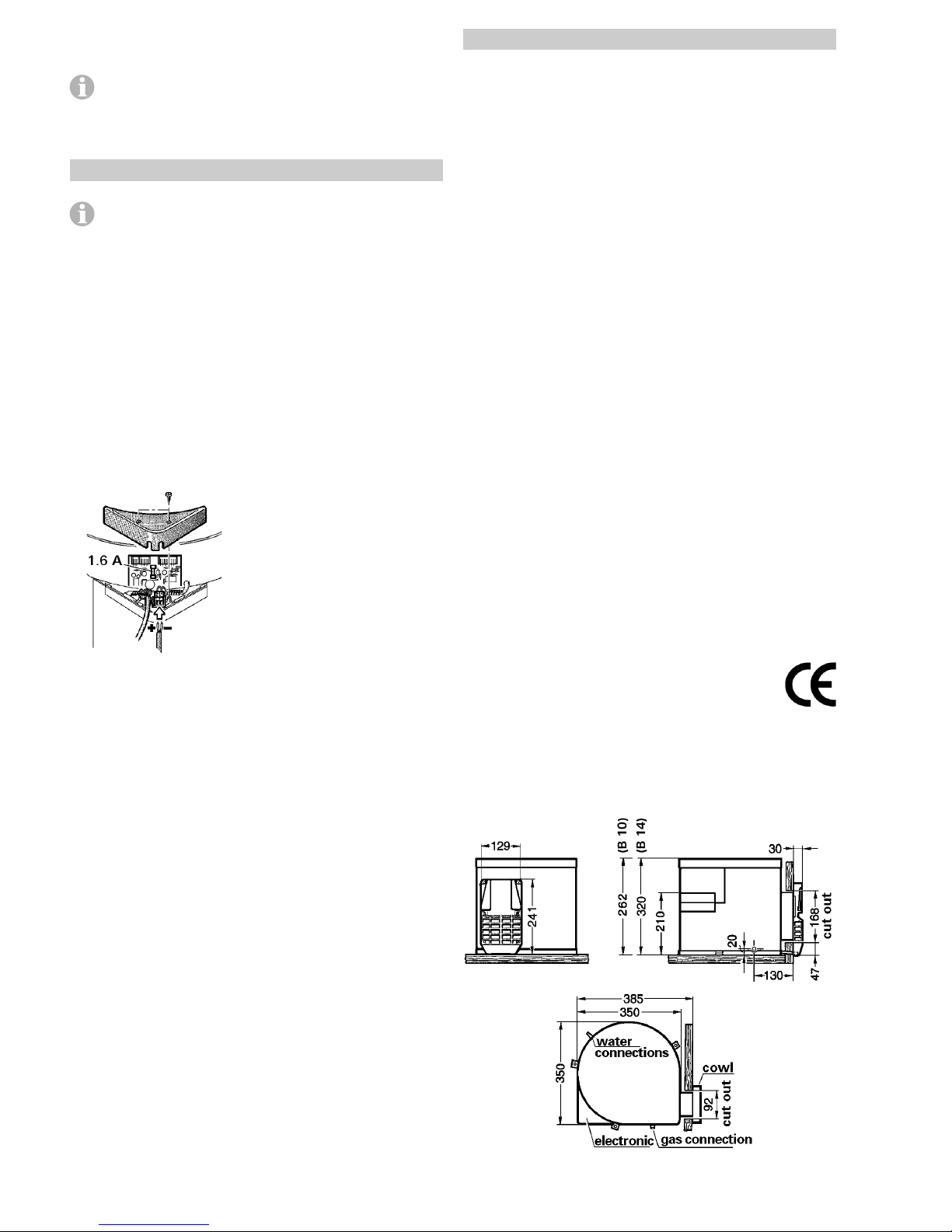
Dimensions:
Switch on at the control panel (h). The indicator lamp indicates
that the electrical water heating is switched on.
The water temperature cannot be selected, automatic
temperature limitation at approx. 70°C! For a faster heat-
ing up period the appliance can be simultaneously operated
with gas and electrical power.
Maintenance
The water tank in the Truma-Boiler is of high quality
food-proof stainless steel VA.
Use wine vinegar for de-scaling the water heater, this being
introduced into the appliance via the water supply. Allow the
product to react and then thoroughly flush out the appliance
with plenty of fresh water. To sterilise the water we recommend „Certisil-Argento”. Other products, particularly those
containing chlorine are unsuitable.
In order to avoid the colonization of micro-organisms, heat up
the Boiler to 70°C at regular intervals.
Do not use the water as drinking water.
Fuses
The water heater 12 V fuse is on the electronic control unit on
the water heater.
Important note: Only replace
the miniature Fuse on the
p.c.b. with a fuse of the same
type: 1.6 A (slow action).
If there is a defect in the electronics, return the control p.c.b.
well padded. If you fail to pack it correctly the guarantee shall
no longer be valid.
Only use original Truma-Boiler control p.c.b.'s as spare parts!
Page 5

5
Manufacturer’s terms of warranty
The manufacturer grants a warranty for malfunctions in the
appliance which are based on material or production faults. In
addition to this, the statutory warranty claims against the seller
remain valid.
The warranty claim is not valid for damage to the appliance
– as a result of not original Truma parts being used in the ap-
pliance and as a result of unsuitable gas pressure regulators
being used,
– as a result of non–compliance with the installation
in structions and instructions for use,
– as a result of incorrect handling,
– as a result of incorrect packaging for transportation.
The warranty is valid for malfunctions as stated above, which
occur within 12 months after conclusion of the purchase
agreement between the seller and the final consumer. The
manufacturer shall rectify such malfunctions by way of repair,
however, the manufacturer also reserves the right to supply a
replacement instead of repairing said malfunctions. Claims for
indirect damage or consequential damage shall be rejected.
This does not affect the rules of the product liability law.
The manufacturer shall bear the cost of employing the Truma
customer service for the removal of a malfunction under warranty – in particular transportation costs, travelling expenses,
job and material costs, as long as the service is carried out in
Germany. Customer service carried out abroad is not covered
by the warranty.
Additional costs based on complicated removal and installation
conditions of the appliance (e.g. removal of furniture or parts
of the vehicle body) do not come under warranty.
In Germany, the Truma Ser vice Center in Putzbrunn/Munich
must always be contacted in event of a malfunction; Abroad,
respective service partners are available (refer to address list).
Com plaints must be specified. In addition, the correctly completed warranty certificate must be presented or the Serial
number of the appliance and the date of purchase specified.
Proof of purchase must be supplied.
Fault finding
Gas operation
Symptom Cause
When switching on, the – No 12 V supply voltage
heater does not operate
Check the power supply (operation voltage min. 10.5 V).
Check the Boiler fuse (refer to maintenance „Fuses“).
When switching on, the – Cowl cover fitted
heater does not operate – Air in the gas supply
and the red lamp lights up – No gas supply
after approx. 30 secs. – Incorrect gas pressure
Remove cowl cover and/or clear any obstruction.
Check gas valves and gas bottle.
To unlock (and purge air), switch off the appliance, wait
5 minutes, and switch on again.
Heater operates for a – Over temperature thermostat
prolonged time and then operated
the red lamp lights up
Check water content, refill if required (close drain valve).
To unlock, switch off the appliance, wait 5 minutes, and switch
on again.
Electrical operation
Symptom Cause
When switching on, the – No 240 V supply voltage
heater does not operate – Over temperature thermostat
operated
Connect the caravan to the site supply and/or check residual
current circuit breaker.
Check water content, refill if required (close drain valve).
The electrical heating element is fitted with an excess temperature cut-out. In event of a fault, switch off at the control panel,
wait 5 minutes, then switch on again.
Water supply
Symptom Cause
Water drips from the – Water pressure to high
safety valve
Check water pressure (max. 400 kPa), use a pressure reducer
when connected to central water supply.
When opening the cold – Hot water flows back
water tap, hot water tap through the cold water
comes out supply
Fit a no-return valve in the cold water supply (refer to installation instructions point 4 „Water connection“).
If fault persists please contact the nearest
Truma-Service.
Page 6
6
Installation instructions
This appliance must be installed by an authorised
person.
This appliance shall be installed in accordance with the manufacturer’s installation instructions, local gas fitting regulations,
municipal building codes, electrical wiring regulations, AS5601
„Gas Installations“, any other statutory regulations and water
supply regulations.
Data label
The data label is located on the top of the water heater.
This appliance is suitable for propane gas only, ensure that the
available gas supply is suitable.
Intended use
This appliance has been designed for the installation in caravans, mobile homes and other vehicles. It is not approved for
installation in boats. Other forms of use are also possible
following consultation with Truma.
Regulations
Any alteration to the appliance (including cowl) or the use of
spare parts and accessories which are important for the functioning of the heater and which are not original Truma parts, as
well as the non-observance of the installation and operating
instructions, shall lead to the cancelling of the guarantee and
exclusion of liability claims. It also becomes illegal to use the
appliance, and in some countries this even makes it illegal to
use the vehicle.
The operating pressure for the gas supply is 2.75 kPa (propane)
and must correspond to the operating pressure of the appliance (see data plate).
When installing the appliance always observe the technical and
administrative rules and regulations of the country in which the
vehicle is to be registered, for the first time!
Water heater kit
The water heater kit contains:
1 Assembled water heater
1 Cowl assembly with screws
1 Hot water connector (12 mm rigid piping)
1 Cold water connector (12 mm rigid piping)
1 Safety (pressure relief) drain valve (12 mm rigid piping)
1 Pressure reducer (12 mm rigid piping)
1 Wall switch (gas operation) with 2.5 m cable
1 Wall switch (230/240 V operation) with 3 m cable – option –
1 Gas inlet connection, 14 mm / 1/4“ BSP
1 Installation template
1 Set literature
1 Label with warning information
In order to guarantee complete emptying of the water content,
ongoing sealing tightness of the water connections and safety
function all enclosed parts must be used!
Choice of location
1. Always install the appliance in such a way that it is easily
accessible for service work at all times and can be easily
removed and installed.
2. Locate the heater in such a way that the cowl can be
mounted on the outside on a surface which is as straight and
smooth as possible.
This outside surface must be exposed to wind from all directions and, if possible, there should be no trim strips or covers
in this area, mount heater on an appropriate base, if necessary.
The cowl must be placed in such a way that the exhaust gas
cannot find its way into the vehicle interior. For this reason,
choose a location where there are no opening windows, skylights or ventilation openings directly above the cowl or for
30 cm on either side. If this is not possible, a warning plate
must be placed on the inside of the window (or skylight) stating that it must be kept closed while the heater is operating. In
this case refrigerator ventilations must be tight-sealed from the
interior of the vehicle.
Installation of the water heater
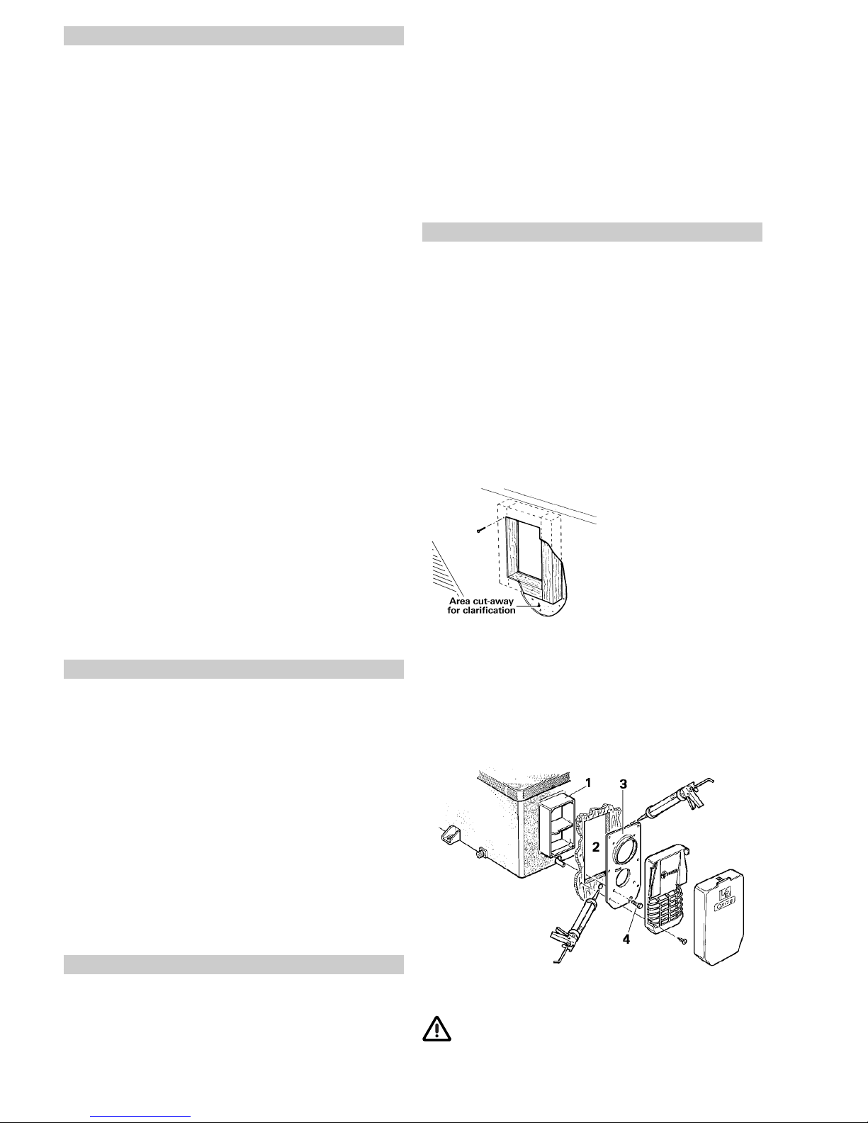
1. Position template for cowl opening on the inside of the wall.
A = Bottom edge of heater
B = Lateral edge of heater
Drill 4 holes (C) with 10 mm dia. through the wall. Drill hole (E)
with 15 mm dia. for condensation tube (also possible from the
outside = F).
2. Position template on the outside of the wall. The markings
(C) must be above the through-holes. Saw cut-out section for
cowl (D) 92 x 168 mm.
If the distance between outside wall and heater is more than
35 mm you must use the cowl extension VBO 2 (please refer
to the last page) with an additional length of 50 mm. Saw out
100 x 176 mm along the dashed line.
If there are any cavities in the
area of the cowl, pack these
with pieces of wood so as to
be able to tighten the screws.
The finished hole should be
168 mm high and 92 mm
wide.
Cut out trim strips or such on the vehicle or place supports
beneath them so as to make the cowl lie flat.
Place a support beneath the heater if the walls are sloping. An
angle of inclination of 10 degrees is not to be exceeded.
3. Insert heater with cowl body (1) through the wall cut-out (2),
allow approx. 5 mm to project out of the wall. Mount sealing
frame (3 – the anti-twisting device ensures correct fitting!).
Pre-drill holes for the 6 fastening bolts (4).
4. Remove sealing frame (3) and coat with non hardening
mastic on the side facing the vehicle – do not use silicone!
The sealing frame must be well sealed with respect to
the front sides and the cross bars of the cowl body (1)
as well as towards the outside wall!
Page 7
7
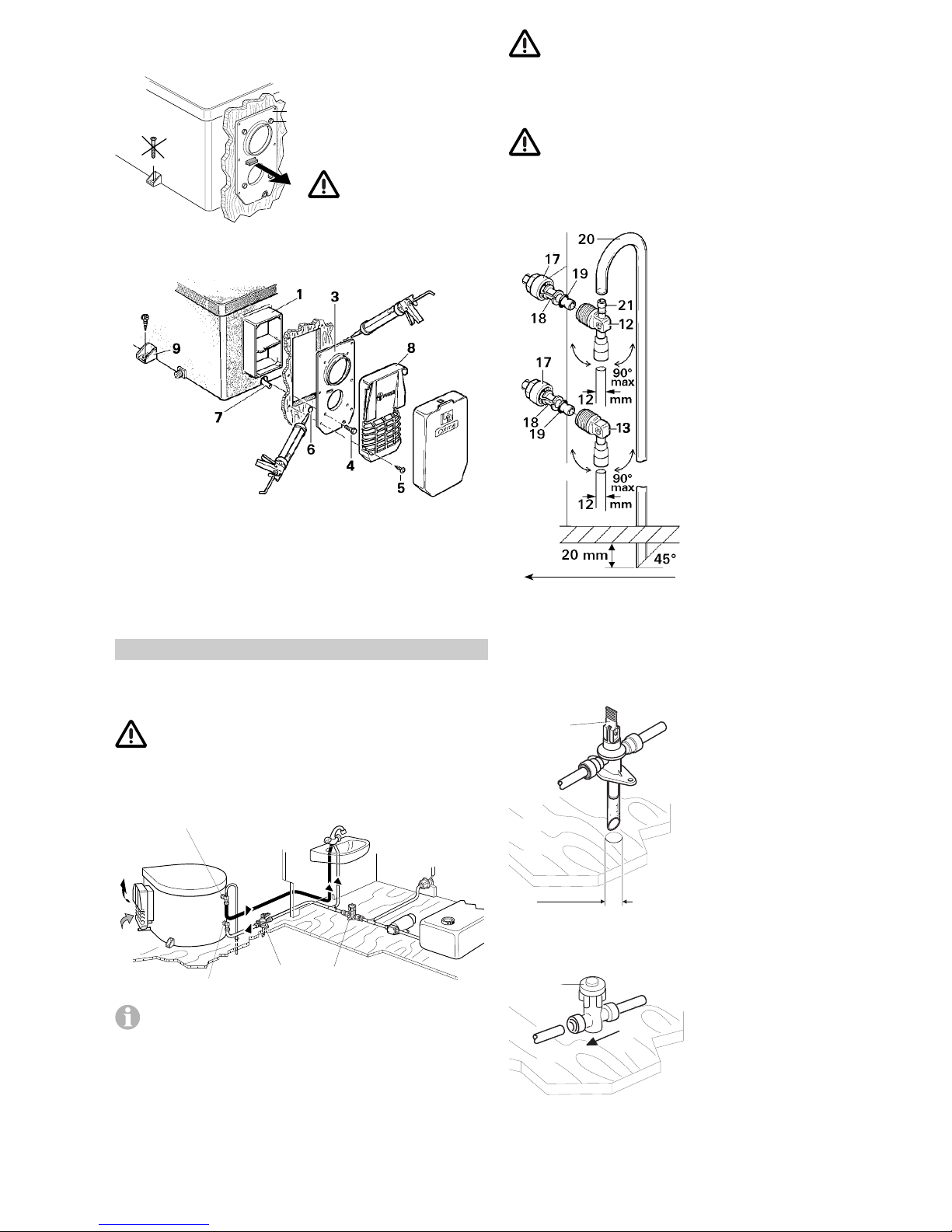
5. Fasten sealing frame (3) to the cowl body using 4 self-cutting
screws (4).
4
3
Screw the sealing frame
(3) in contact together
with the cowl body (1) so the
anti-twist device projects out!
6. Seal the gap between the hole (6) and the condensation
tube (7) with non hardening mastic – do not use silicone!
7. Mount the grille (8). Press the entire cowl assembly onto the
vehicle wall and fasten with 6 screws (5).
8. Screw the boiler securely to the floor of the vehicle with
at least two shackle plates (9) with the screws provided,
B 5.5 x 25, on suitable base (plywood panel, laminated wood
strips or metal base).
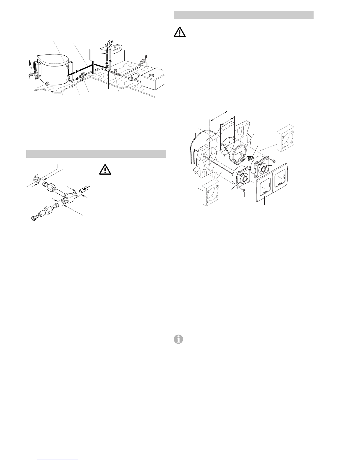
Water connection
All pressure and submergible waterpumps can be used for
operating the water heater.
In order to guarantee complete emptying of the
water content and to prevent pressures of greater
than 400 kPa occurring in the boiler, the enclosed pressure reducer (10), the enclosed water connectors (12 +
13) and the enclosed safety (pressure relief) drain valve
(14) must be used!
12
13
14
10
The supplied water connectors (12 + 13) and safety/drain
valve (14) have a 12 mm rigid piping connection (e.g.
John Guest System). For connecting to rigid pipes with other
diameters appropiate adapters (not included in scope of
delivery) must be used.
As special accessories Truma supplies the water connectors
(12 + 13) and safety/drain valve (14) with a 10 mm / 3/8“
diameter hose nipple (please refer to the last page).
Route water pipes so that they are as short and free of
kinks as possible (hose connections must be secured
using hose clamps – also for cold water! – pressures of up
to 400 kPa can occur in the safety/drain valve – also with submergible pumps – because of the heat of the water and the
resulting expansion).
All hot water pipes should be routed in a descending
manner to the safety/drain valve! Otherwise no guarantee of protection from frost!
Installation of the elbow water connectors
Screw elbow with integrated
breather valve (12) to hot
water connection pipe (upper pipe) and elbow without
breather valve (13) to cold
water connecting pipe (lower
pipe).
Slide on nut (17), tension
ring (18) and O-ring (19). Assemble screw connector and
connecting pipe and fasten
together using nut (17).
Slide ventilation hose with
11 mm outer diameter (20)
onto the breather valve hose
nozzle (21) and route towards
the outside. Do not allow the
radius of the arc to be less
than 40 mm.
Cut off the ventilation hose
approx. 20 mm below the
floor of the vehicle at an
angle of 45° to the direction
of travel.
Installation of the safety (pressure relief)
drain valve
Ø 18 mm
14
Install the safety/drain valve
(14) at a place which is eas-
ily accessible, near the wa-
ter heater. Drill a hole with
18 mm diameter and pass
through the discharge tube.
Fasten safety/drain valve with
two screws. The draining is to
be directly to the outside at
a position protected against
splash water (apply splash
guard, if necessary).
Installation of the pressure reducer
10
The pressure reducer (10)
must be fitted between the
safety/drain valve and water
pump in accordance to the
direction of flow. Fasten the
pressure reducer to the floor.
Direction of travel
Page 8
8
Water pipe routing
1. Connect the cold water supply (15) via the pressure reducer
(10) to the safety/drain valve (14).
12
13
14
10
16
15
22
2. Produce connection (16) for cold water supply between
safety/ drain valve (14) and elbow (13 – lower pipe) on water
heater.
3. Route the hot water pipe (22) from the elbow with integrated
breather valve (12 – upper pipe) to the hot water consumers.
Gas connection
14 mm
14 mm
1/4"
The gas inlet connection on the Boiler is a
14 mm metric connection.
To connect, the 1/4" BSP
male gas inlet connection
provided with the appliance
must be used.
Check for gas leaks (do not check for gas leaks with a naked
flame), then check that the gas pressure is as follows:
Propane gas: 2.75 kPa
Before connecting to the water heater make sure that the gas
lines are free from dirt, chips and such!
Route the pipes in such a way that the appliance can be
removed again for servicing.
The gas system must comply with the technical and administrative regulations of the country in which the appliance is
used.
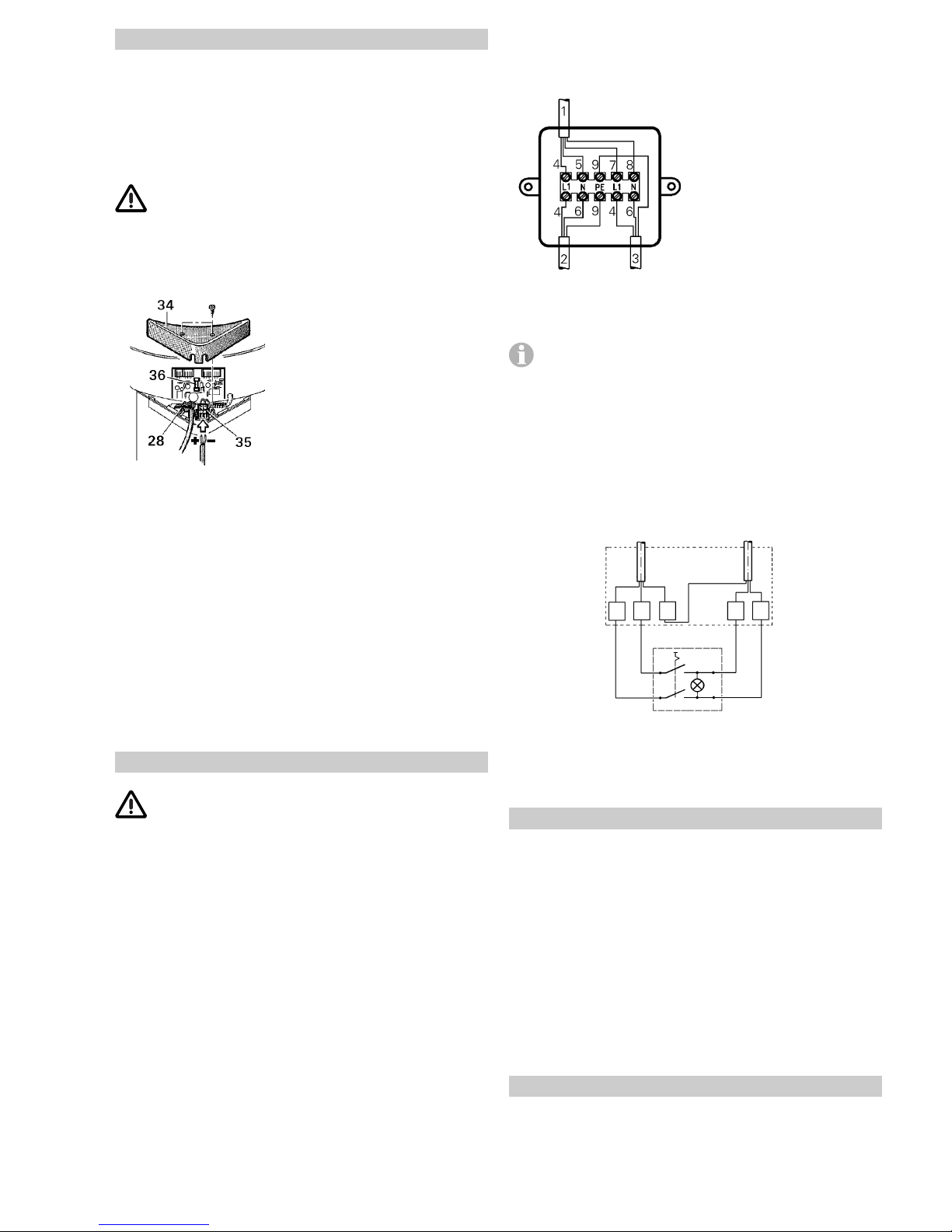
Installation of the control panels
When using control panels which are specific to the ve-
hicle or the manufacturer, the electrical connection must
be established in accordance with the Truma interface descriptions (refer to Electrical connection 230 V). Any modification
made to the Truma components pertaining to this will lead to
the invalidation of the guarantee, as well as to the exclusion of
any claims for liability. The installer (manufacturer) is responsible for providing instructions for use for the user as well as for
identification printing on the control panels.
When selecting the location, bear in mind that the control panels must not be subjected to direct radiant heat. Length of connection cable 2.5 m. If required, a cable extension of 5 m can
be supplied (refer to last page).
66 mm
Ø 55 mm
30
29
28
28
25
32
32
26
31
31
27
25
1. The control panel for gas operation (26) and (if provided) the
control panel for electrical operation (27) should be fitted next
to one another if at all possible (distance between centres of
holes 66 mm).
2. In each case, drill a hole with diameter 55 mm (distance
between centres of holes 66 mm).
3. Plug the control panel cable (28) to the control panel for
gas operation (26) and then fit on the rear cover cap (29) as a
stress-relieving device.
4. Push the cable through to the rear and lay the connection
cable (28 + 30) to the boiler.
5. Lay the connection cable with the orange multipole connector (28) to the 12 V control electronics unit (for connection
refer to Electrical connection 12 V).
6. Secure both control panels with 4 screws (31) each and fit
the cover frame (32) on them.
If a flush installation of the control panels it is not possible, use the surface-mounting frame (25) as supplied.
Page 9
9
Connection with Truma control panel supplied
1. Connect control panel cable, supply line 230/240 V and
heating element cable as shown in the drawing.
1 = Control panel cable
2 = Supply line 3 x 1.5 mm²
3 = Heating element cable
4 = brown
5 = green
6 = blue
7 = yellow
8 = white
9 = yellow/green
2. Assemble the splitting box on the vehicle floor or on the
wall, in the vicinity of the appliance (observe cable length
110 cm!).
All cables must be secured with cable clips.
Conection 230/240 V with specific vehicle or
manufacturer control panels
Connect control panel cable, 230 – 240 V cable and heating
element cable as shown in the drawing.
Cables must be in accordance with the technical rules and regulations of the country in which the vehicle is to be registered,
for the first time.
Function check
After installation, check gas supply line for leaks in accordance
with the pressure drop method. Following this, check the function of the appliance as specified in the operating instructions,
check the function of the draining of the water contents, in
particular. There shall be no claims under guarantee for
damage caused by frost!
Never operate the water heater without water contents.
It is, however, possible to briefly check the electrical function
without water contents. Always observe the operating instructions prior to operation!
The operating instructions and completed guarantee card are
to be given to the owner of the vehicle.
Warning information
The installer or vehicle owner must apply the yellow sticker
with the warning information, which is enclosed with the appliance, to a place in the vehicle where it is clearly visible to
all users (e.g. on the wardrobe door)! Ask Truma to send you
stickers, if necessary.
Electrical connection 12 V
Always disconnect the appliance from the power supply prior
to working on electrical components. It is not sufficient to just
switch off at the control panel!
The appliance must be disconnected from the vehicle main
power supply when carrying out any electric welding work on
the vehicle body.
If the connections are transposed there is a risk of cable
burning. This also rules out any guarantee or liability
claims.
Unscrew cover (34) from the electronic control unit. Slide cable
connector of control panel (28) onto the p.c.b.. The electrical
connection is made at terminal (35).
Orange = Positive 12 V
Blue = Negative
To connect press with a small
screwdriver from above and
push in cable from the front.
Connect to fused vehicle mains (central electrical equipment
5 – 10 A) using a 2 x 1.5 mm² cable.
Negative cable to central earth. With lengths of over 6 m use
a cable 2 x 2.5 mm². If connecting directly to the battery, the
positive and negative cable must be fused. Screw cover (34)
back on.
There are to be no other 12 V consuming appliances connected to the supply line!
The water heater fuse (36), 1.6 A, (slow-acting) is on the
p.c.b..
When power supplies are being used, it must be noted that the
output voltage is between 11 V and 15 V and the alternating
current ripple is < 1.2 Vss.
Electrical connection 230/240 V – option –
The electrical connection is only to be carried out by a
licensed electrician. The information given here is not
intended as information for the layman, rather it is to for assisting the assigned electrician, as additional information, when
connecting the appliance!
The connection to the power supply is by means of a cable
3 x 1.5 mm² (e.g. flexible sheathed cable H05VV-F) to a
splitting box (not included in scope of delivery).
Always pay attention to connect carefully with the correct
colours!
For maintenance and repair work a disconnecting device must
be provided on the vehicle for all-pole disconnection from the
power supply, with at least 3,5 mm contact clearance.
supply line
230/240 V
3 x 1.5 mm²
heating
element
splitting box
control panel
PEL
N
N’ L’
Page 10
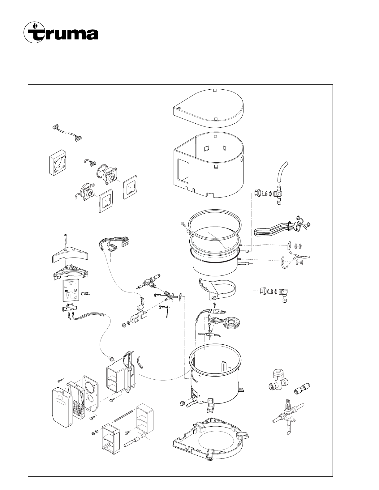
10
Boiler
L. P. Gas and 230/240 V Electric
Storage Water Heater
Model B 10 / B 14
from 11/2003
When ordering spare-parts, please always specify the fabrication number and year of make
Page 11
✂
Guarantee Card
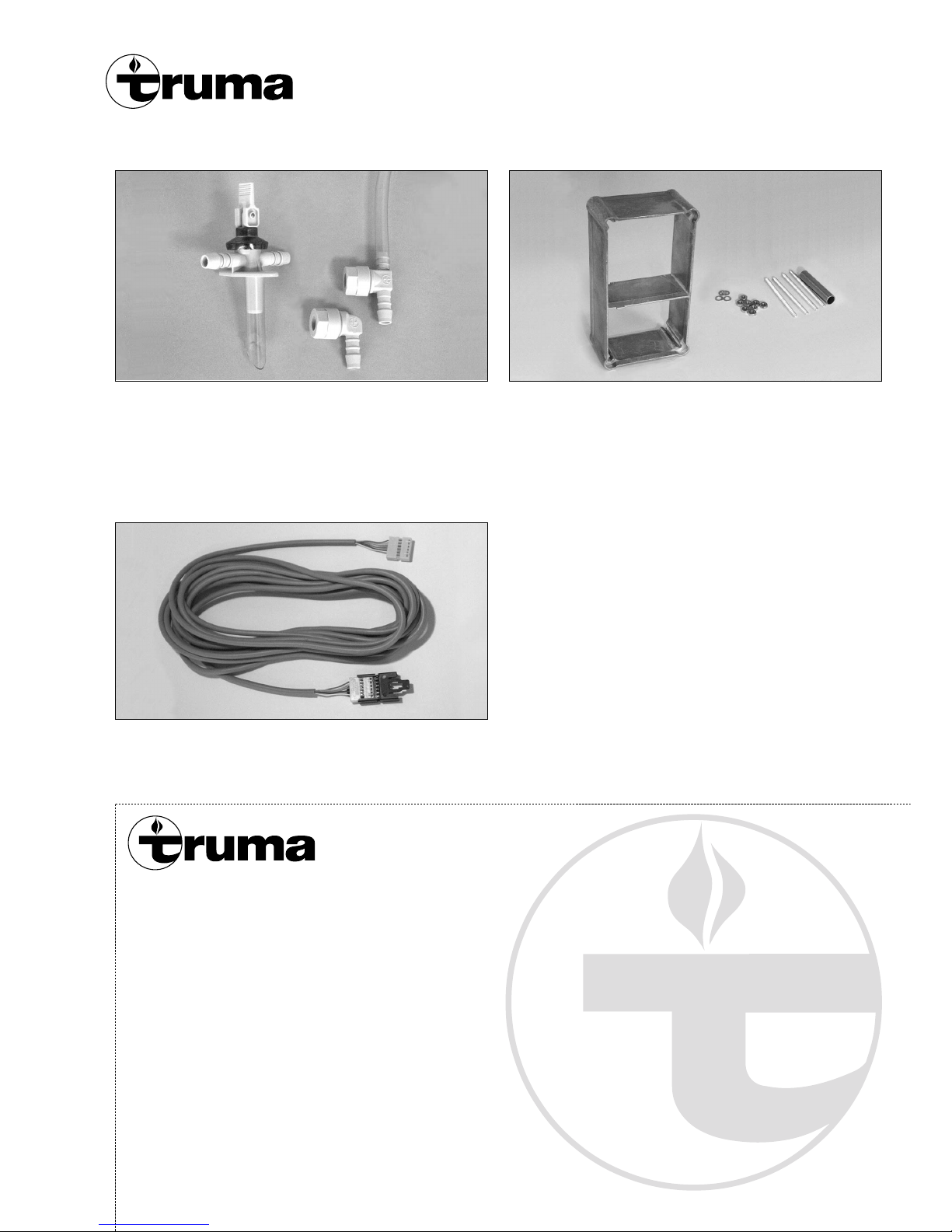
Accessories
Safety/drain valve and water connectors
for flexible water hoses
34150-01 Hot water connector, 10 mm / 3/8“
70150-01 Cold water connector, 10 mm / 3/8“
70141-02 Safety/drain valve (400 kPa), 10 mm / 3/8“
Cowl extension for wall thicknesses over 35 mm
70131-00 Cowl extension VBO 2
Control panel extension cable
70000-53500 Control panel extension cable 5 m
Page 12
Quality with tradition
Truma was founded in 1949 and has since become the leading
European manufacturer of vehicle and boat liquid gas heaters.
The entire programme of Truma products is designed to run on
clean liquid gas fuel.
Using the knowledge gained from practical experience, over
the years Truma has developed warm air systems, storage
water heaters, air conditionings, lamps, pressure regulators
and accessories for Caravans and mobile homes and therefore
decisively influenced the development of the camping scene
as a whole.
Today Truma is the internationally acknowledged brand leader,
operating on the basis of the certified quality management
system according to ISO 9001.
✂
To be filled in by the dealer.
Date of sale
02/2006 · Truma, P.O. Box 1252, 85637 Putzbrunn / Germany
Guarantee Card
Serial number
Boiler
Model B 10
Model B 14
Dealer’s address
70010-28700 · 06
·
02/2006 · 1’ B · ©
water content:
10 l
14 l
 Loading...