

Page 1
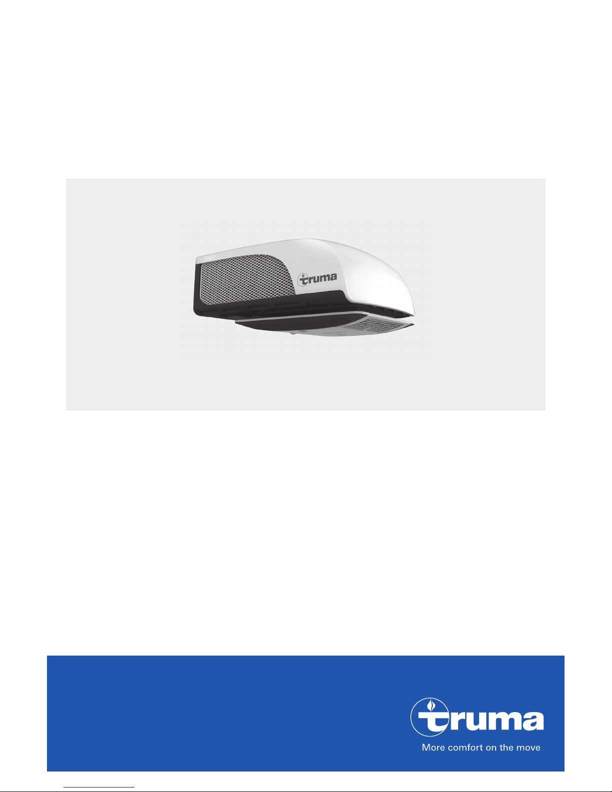
Operating instructions
To be kept in the vehicle
Aventa compact plus AU
Page 2
2
Contents
Symbols used ........................................................................ 2
Safety instructions ............................................................. 2
Notes on using air conditioning systems ....................... 3
Operating instructions
Remote control ...................................................................... 4
Start-up .................................................................................. 5
Switching on ......................................................................... 5
Mode ..................................................................................... 5
Fan ......................................................................................... 5
Sleep function ....................................................................... 5
Switching off ......................................................................... 5
Time ....................................................................................... 5
Timer ON / OFF ...................................................................... 5
* Ambient lighting ................................................................. 5
Reset ...................................................................................... 5
Resend ................................................................................... 5
Setup ..................................................................................... 5
IR receiver and manual on / off ............................................. 6
IR receiver / function display ................................................. 6
Red LED illuminated .............................................................. 6
Air distribution ....................................................................... 6
IR remote control battery change ......................................... 6
Disposal ............................................................................... 6
Maintenance ....................................................................... 6
Disposal ............................................................................... 6
Accessories ......................................................................... 7
Troubleshooting ................................................................. 7
Technical data ..................................................................... 8
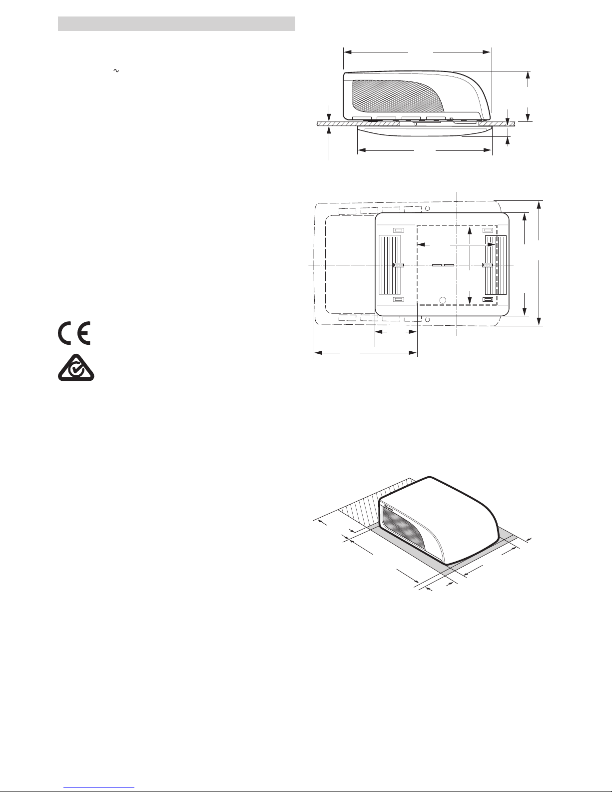
Installation dimensions (in mm) ............................................ 8
Clearance around the air conditioning system ...................... 8
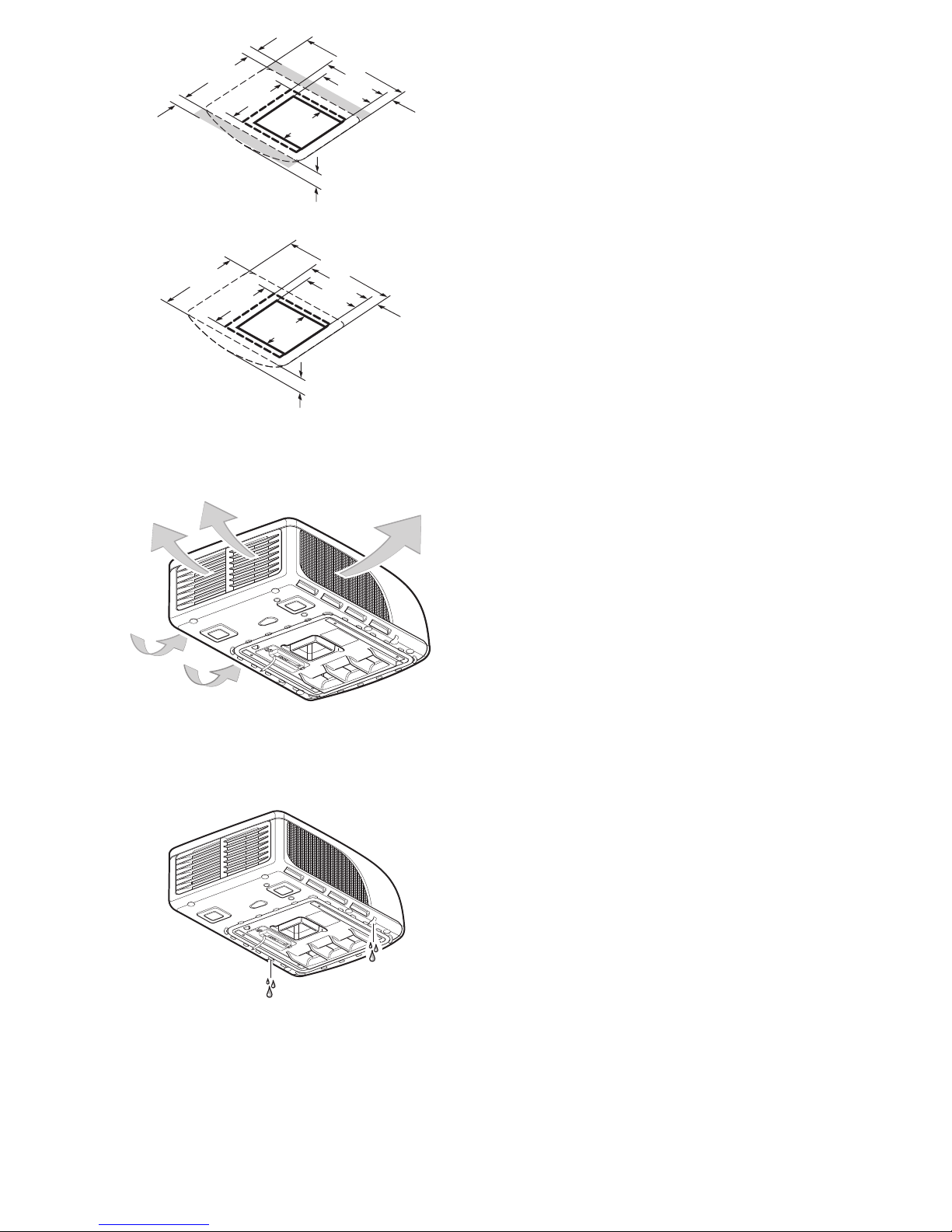
Air inlets / outlets ................................................................... 9
Condensation traps ............................................................... 9
Truma warranty policy ..................................................... 9
Aventa compact plus AU
Symbols used
The device must only be installed and repaired by an
expert.
Symbol indicates a possible hazard.
Note containing information and tips.
Safety instructions
Only competent and trained persons
(experts) may install, repair or perform
the function check on the Truma product in
accordance with the installation and operating instructions and the currently accepted
technical regulations. Experts are persons
who, based on their specialist instruction and
training, their knowledge and experience with
Truma products and the relevant standards,
can carry out the necessary work properly and
identify potential hazards.
The appliance must be installed in accordance
with the national installation regulations.
This appliance may be used by children from
8years old and by persons with reduced physical, sensory or mental capabilities or with a
lack of experience and knowledge only if they
are supervised or have been instructed in the
safe use of the appliance and understand the
resulting risks.
To avoid transportation damage, the device
may only be sent to the Truma Service Centre
if agreed beforehand.
The power supply must be disconnected
from the mains (all poles) before opening the
housing.
The device fuses and connection cables must
only be replaced by experts.
The 230 V, T 6.3 A H (slow) device fuse can
be found on the electronic control unit in the
device and must always be replaced with an
identical fuse.
Page 3

3
Guarantee claims, warranty claims and acceptance of liability will be ruled out in the
event of the following:
– changes to the device (including
accessories),
– failure to use original Truma parts as replace-
ment parts and accessories,
– failure to follow the installation and operat-
ing instructions.
Such changes or non-compliance also invalidate the device operating permit, which in
many countries also denotes expiry of the vehicle operating permit.
The refrigerant circuit contains R 407C refrigerant and must only be opened in the
factory.
The air inlets / outlets at the external unit and
the air distributor must not be obstructed
under any circumstances. This is essential
in order to ensure that your device operates
correctly.
To prevent damage to the appliance, it should
not be operated continuously at an incline of
more than 8 %.
Do not operate the device in cooling mode
for long periods with the vehicle at an angle, since the condensation that is produced
may not be able to run away and may penetrate the vehicle if the circumstances are
unfavourable.
For problem-free operation and in order to
avoid damage, the supply voltage must always come from a source with a sine wave
curve (e.g. voltage converter, generator) and
without voltage spikes.
When the vehicle is being cleaned it must be
ensured that no water gets into the device
when spraying with a high-pressure cleaner,
for example (do not spray directly into the
openings of the device).
Hot cleaners and steam cleaners must not be
used.
Condensation traps must always be
unobstructed.
Notes on using air conditioning systems
You should still check whether the camp site
has adequate fuse protection (min. 6 A) before
starting the equipment up.
Park the vehicle in the shade if possible.
Darkening with blinds reduces the amount of
heat insolation.
Clean your roof at regular intervals (dirty roofs
heat up more than clean roofs).
Ventilate your vehicle well before starting the
equipment in order to remove accumulated
warm air from the vehicle.
In order to obtain a healthy room climate, the
difference between the inside and outside
temperatures should not be too great. The
recirculated air is cleaned and dried during operation. A pleasant room climate is produced
by drying the moist air, even with small temperature differences.
Keep all doors and windows closed when in
cooling mode so that no condensation buildup occurs at the air distributor.
For faster cooling or heating:
– Set fan level to high,
– Set front / rear air distribution to centre
position,
– Set floor / ceiling air distribution to ceiling.
Page 4
4
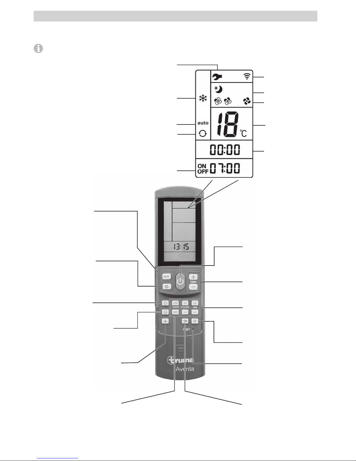
Remote control
The symbols in the display are visible depending on the
settings.
Fig. 1
Sleep function
Ultra-quiet fan operation by
reducing the speed of both fans
* Ambient lighting
The lighting is dimmed by pressing
and holding down the button.
Pressing it again deactivates
or activates the lighting.
Mode
Mode selection button
– Cooling
– Automatic
– Circulated air
Temperature selection buttons
16 – 31 °C
In 1 °C steps
On / O switch
Reset
Resets the remote control
to the factory settings.
Fan level
– low
– medium
– high
Resend
Retransmit data
Time selection
button
Time setting
Setting for clock time
and timer
Timer selection button
Switch-on / switch-o time
can be set up to 24 hours in advance
* No function in the case of air distributor small
Timer
On/O time
Cooling
Setup
Resend /
data transmission
Circulated
air
Fan level
Sleep function
Temperature
Time
Automatic
mode
Setup button
Tuning the remote control
and the IR receiver
Operating instructions
Page 5

5
Start-up
Before switching on, be sure to check that the camp site has
adequate power supply fusing (230 V).
In order to prevent the power cable of the recreational
vehicle from overheating (minimum cross-section
3x2.5 mm²) the cable drum must be fully unwound.
The remote control must always be pointed at the infrared receiver in order to perform the individual switching commands.
Before switching on for the first time, the remote control must
be tuned to the IR receiver.
– Insert batteries (pay attention to polarity)
– Setup symbol flashes
(if symbol does not flash, perform Reset)
– Point remote control at IR receiver
– Press Setup button and hold down
– When the red LED on the IR receiver starts to flash, release
the Setup button.
The remote control is tuned to the IR receiver, the Setup symbol goes off and the air conditioning system starts in circulated air mode, at low fan level and with no timer set.
Switching on
Switch on the air conditioning system using the “On / Off
switch” of the remote control. The last selected settings are
taken over.
The circulated air fan runs after switching on. The compressor switches itself on after no more than 3 minutes,
and the blue LED flashes.
Temperature
If necessary, use the “Temperature selection buttons” to
set the required room temperature with “+” and “–”.
Mode
Select the required operating mode by pressing the “MODE”
button one or more times.
– Cooling
– Automatic
– Circulated air
When the room temperature that was selected using the remote control is reached in cooling mode, the compressor
switches off and the blue LED in the IR receiver goes off. The
circulated air fan continues to run in order to provide ventilation. If the room temperature setting is exceeded, the appliance automatically reverts to cooling mode.
. If the air humidity in the vehicle is extremely high at
the beginning of the cooling procedure, moisture can
build up on the underside of the air distributor. The doors and
windows should therefore be kept closed and the highest fan
level selected.
In automatic mode, the fan level is selected automatically
depending on the room temperature.
In circulated air mode, the interior air is recirculated and
cleaned by the filters / panels No LED’s illuminate in the
IR receiver.
Fan
Select the required fan level by pressing the “Fan level” but-
ton one or more times.
Fan level (not functional in automatic mode):
– low
– medium
– high
Sleep function
In “Sleep function” the internal and external fans operate at
slow speed and are therefore extremely quiet.
Switching off
To switch off, press the “On / Off switch” on the remote
control. The remote control and the appliance are switched off.
* The light can still be switched on and off using the
“Ambient lighting” button.
* No function in the case of air distributor small
The blue LED flashes when the air conditioning system
is switched back on. The circulated air fan runs, and the
compressor switches on after no more than 3 minutes.
Time
Press the “Time selection button” and set the current time
using the “Time setting” buttons.
The time is always shown on the display (exception with
ON /OFF timer).
The time must be reset after changing the batteries or after a
daylight saving time change.
Timer ON / OFF
The On / Off time of the air conditioning system can be set
in advance for a minimum of 15 minutes to a maximum of
24 hours, starting from the current time, using the integrated
timer.
The appliance must be switched on using the remote control
in order to program it.
Set required operating mode and room temperature.
Then select TIMER ON or TIMER OFF using the “TIMER
selection buttons”. Set the required On / Off time using
the “Time setting” buttons (15 minutes to 24 hours) and
confirm with TIMER ON or TIMER OFF.
Pressing the relevant timer button again deactivates the timer
function.
* Ambient lighting
Irrespective of whether the air conditioning system is operating, the lighting in the air distributor can be switched on or
off by pressing the “Ambient lighting” button. The lighting is dimmed by pressing and holding down the “Ambient
lighting” button. The previous setting is activated when it is
switched on again.
* No function in the case of air distributor small
Reset
Resets the settings of the remote control to the factory settings when pressed using a ballpoint pen, for example. Setup
symbol flashes.
Resend
The previous settings are resent.
Setup
Tune the remote control to the air conditioning system that is
going to be operated.
Page 6
6
IR receiver and manual on / off
There is an additional pushbutton on the IR receiver (m), with
which the unit can also be switched on and off without the
remote control (e.g. with a ballpoint pen).
If the unit is switched on using this pushbutton, the system is
automatically reset to the factory settings (automatic mode,
22 °C).
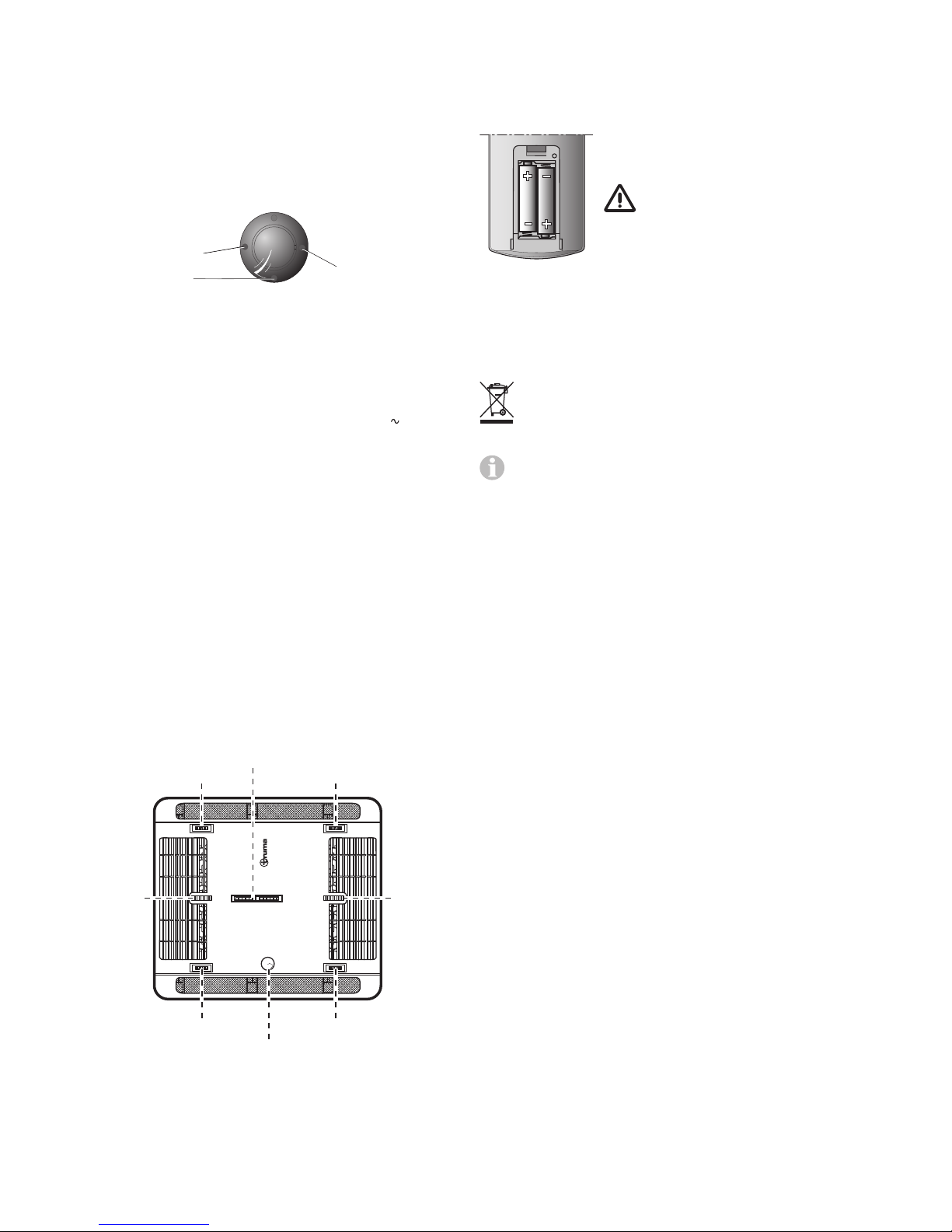
IR receiver / function display
LED 2
LED 1
m
Figure 2
LED 1 blue – illuminated – (cooling mode)
LED 1 blue – flashing – (cooling mode compressor start-up)
LED 2 red – flashing – (data transfer in progress)
LED 2 red – illuminated – (fault)
LED 1 and LED 2 illuminated (230 V interrupted
,
compressor switches off)
Red LED illuminated
The appliance is indicating a fault. Switch the appliance off,
wait for a short time and switch on again. If red light stays on,
contact Service Australia.
Air distribution
Right / left
There are two individually adjustable air outlets at the front
and rear.
Front / rear
The air flow can be metered between the front and rear areas
of the vehicle.
Ceiling / floor
The air flow can be directed from the ceiling to the floor.
Aventa
Right / leftRight / left
Right / left
Right / left
IR receiver /
function display
Front / rear
Ceiling /
floor
Ceiling /
floor
Front
Front
RearRear
Figure 3
IR remote control battery change
Only use micro-batteries that will not leak, type LR 3, AM4,
AAA, MN 2400 (1.5 V).
The battery compartment is on the back of the remote control.
When inserting new batteries, make sure
the positive / negative terminals are connected correctly.
Empty, used batteries can leak
and damage the remote control!
Remove the batteries if the remote control is not being used for a long period of
time.
Figure 4
No warranty is given for damage caused by leaking
batteries.
Disposal
Neither the remote control nor the batteries may be
disposed of with domestic refuse, instead they must be
sent for recycling separately via a collection point. By
doing this you are contributing towards reuse and recycling.
The tuning between the remote control and the air conditioning system is retained if the batteries are removed.
Maintenance
Maintenance, repairs and cleaning must not be done by
children.
Carry out filter changes depending on the amount of use, but
at least every 12 months.
On the air distributor small, remove the panels and clean under clear / lukewarm water.
Never operate the air conditioning system without a filter /
panels. This can lead to loss of power. Keep the air inlets /
outlets and the condensation traps on the roof free of obstructions such as leaves at all times. The air conditioning system
should only be cleaned with a soft, damp cloth.
Disposal
The appliance must be disposed of in accordance with the administrative regulations of the respective country in which it is
used. National regulations and laws (in Germany, for example,
the End-of-life Vehicle Regulation) must be observed.
The relevant regulations must be observed in other countries.
Page 7

7
Troubleshooting
Fault Cause / Remedy
Appliance not cooling – Thawing procedure in progress
– Remote control temperature
setting reached or too high
Appliance providing insufficient cooling or no
cooling at all
– Filter / panels dirty, replace
filter/clean panels
– External air routes soiled /
blocked
Moisture on underside
of air distributor
– Close windows and doors and
select high fan level
Water dripping out of
air distributor
– Condensation trap on external
unit blocked
– Seal between appliance and
roof not intact
– System at too much of an angle
Remote control
not working
– Check batteries in remote con-
trol and replace if necessary
Appliance not reacting to remote control
commands
– Check whether there are ob-
structions between the remote
control and the IR receiver
– Is the remote control tuned to
the IR receiver / Tune remote
control to IR receiver.
Compressor switches
off and back on again
after approx. 3 minutes
– Voltage drop at 230V
power
supply / check 230V
power
supply
If these actions do not remedy the problem, please contact Service Australia.
Accessories
Aventa air filter kit, 2 pcs
for air distributor, not for air distributor small
(Part. No. 40091-16800)
Figure 5
Page 8
8
Installation dimensions (in mm)
670
556*
785
265
46
25 - 110
Figure 6
400
(380)
400
(350)
523 / 496*
192
(212)
310
560
Figure 7
*air distributor small
Clearance around the air conditioning system
The clearance around the external unit must be 20 mm at
the front and 50 mm at the side. At least 20 mm of clearance
must be left at the rear. Truma recommends clearance of
50 mm so that the exhaust air can blow out freely.
50
560
50
50
785
20
20
Figure 8
The clearance around the air distributor must allow the air
to blow out without obstructions. The side clearance must be
at least 40 mm (not in the case of the air distributor small).
The pivoting range of flaps and doors must be taken into
consideration.
Technical data
Determined on the basis of EN 14511 or Truma test conditions
Power supply
230 V – 240 V
, 50 Hz
Power consumption
Cooling: 4.4 A
Starting current
28 A (150 ms)
Cooling power
2.2 kW (T35 /T35)
Air volume flow
max. 400 m³/h
Usage limits
+16 °C to 40 °C
Maximum angle during operation
8 %
Weight
29.5 kg with installation materials
Dimensions (W x H x D)
External: 560 x 265 x 785 mm
Internal: 523 x 46 x 670 mm (air distributor)
Internal: 496 x 46 x 556 mm (air distributor small)
Refrigerant
R 407C / 0.47 kg
Contains fluorinated greenhouse gases covered by the Kyoto
Protocol. Hermetically sealed.
Global Warming Potential (GWP)
1774
CO2 equivalent
833.8 kg
Subject to technical changes.
Page 9
9
Truma warranty policy
The warranty is given by Service Australia for 12 months from
the date of purchase against any defect arising from faulty
materials or workmanship.
Repairs will be carried out during normal business hours only
by Service Australia, or its duly authorised service agents,
and are subject to the warranty conditions and exclusions
hereunder.
Warranty conditions
– The company will only provide service on presentation of
proof of purchase, on either the Truma product, or the Caravan / RV / Pleasure Craft in which the Truma product has
been installed, to any authorised service agent. The purchaser must allow the service agent to photocopy the proof of
purchase to facilitate his claim to the manufacturer.
– Warranty repairs can only be performed by authorised
service agents and under no circumstances will Service
Australia reimburse repairs carried out by unauthorised persons. Tampering with any part of the product by unauthorised personnel will automatically void the warranty.
– The product must be used solely for domestic purposes
only. If the product is used for commercial purposes the
warranty is 6 months only.
– Where applicable, the products must be used on the appro-
priate electrical voltage, gas type and pressure, or fuel
source.
– If at any time during the warranty period any part or parts
are replaced with a part or parts not supplied or approved
by Truma, this warranty shall immediately become void.
Important notice
Before calling a service technician please check carefully the
operating instructions, service booklet and warranty terms and
conditions. If the product fails for any of the reasons detailed
therein, or is faulty due to abuse, misuse or improper installation, then a service fee shall be charged to the purchaser.
If you have any queries regarding the interpretation of the
warranty you should contact Service Australia.
Whilst this book represents service outlets at the time of
printing, changes occur from time to time. Should you have
any queries or wish to locate your nearest authorised service
agent please contact Service Australia.
Warranty does not cover
– Any appliance which has been:
(a) Subject to misuse, neglect, accident or alteration by any
person.
(b) Damaged or destroyed by fire, flood, act of God or other
inevitable accident.
– Fair wear and tear.
– Damage from foreign substances such as dirt or liquid.
– Travelling expenses or call out fee to and from authorised
service agents premises.
– Accommodation or Site Expenses.
– Cleaning of the system. This is considered to be a part of
normal product maintenance.
– Non operation of the appliance or resultant damage to the
unit where the appliance has been operated in an out of
level situation.
– Freight cost of the appliance or parts, to or from, point of
service or transit damage.
– Service Australia / Truma are not responsible for resultant
loss or damage sustained by the purchaser.
– Non operation of the appliance or resultant damage to the
unit where the appliance has not been installed, ventilated,
flued or operated in accordance with the manufacturers
instructions.
Apart from any warranties implied by the Trade Practices Act
1974 or any relevant State legislation all other warranties express or implied whether arising by virtue of statute or otherwise are hereby excluded.
400
670
380
78
523
400
350
40
40
46
FRONT
Figure 9 – Air distributor
400
556
380
50
496
400
350
46
FRONT
Figure 9 a – air distributor small
Air inlets / outlets
Figure 10
Condensation traps
The condensation is led away via the roof of the vehicle.
Figure 11
Subject to technical changes.
Page 10

Page 11

Page 12

Leisure-Tec Australia Pty. Ltd.
50 Metrolink Circuit,
Campbellfield, VIC 3061
Australia
Service Australia
Telephone: +61 1300 07 2018
E-Mail: [email protected]
In Australia, always notify the Service Australia
if problems are encountered; in other countries
the relevant service partners should be contacted
(www.truma.com).
Having the equipment model and the serial number
ready (see type plate) will speed up processing.
40091-00439 · 00 · 01/2019 · ©
 Loading...