


DE Gebrauchsanweisung
Einbauanweisung
Im Fahrzeug mitzuführen
EN Operating instructions
Installation instructions
To be kept in the vehicle
FR Mode d‘emploi
Instructions de montage
À garder dans le véhicule
IT Istruzioni per l‘uso
Istruzioni di montaggio
Da tenere nel veicolo
NL Gebruiksaanwijzing
Inbouwhandleiding
In het voertuig meenemen
DA Brugsanvisning
Monteringsanvisning
Skal medbringes i køretøjet
SV Bruksanvisning
Monteringsanvisning
Skall medföras i fordonet
CS, EL, ES, ET, FI, HU,
LT, LV, NO, PL, PT, RU,
SK, SL
Aventa compact
Seite 02
Seite 10
Page 15
Page 23
Page 28
Page 36
Pagina 41
Pagina 49
Pagina 54
Pagina 62
Side 67
Side 75
Sida 80
Sida 88
Page 95

2
DE
Inhaltsverzeichnis
Verwendete Symbole ............................................................ 2
Sicherheitshinweise .......................................................... 2
Hinweise zur Benutzung von Klimasystemen .............. 3
Gebrauchsanweisung
Fernbedienung ...................................................................... 4
Inbetriebnahme ..................................................................... 5
Einschalten ............................................................................ 5
Mode ..................................................................................... 5
Gebläse .................................................................................. 5
Sleep-Funktion ...................................................................... 5
Ausschalten ........................................................................... 5
Uhrzeit ................................................................................... 5
Timer ON / OFF ..................................................................... 5
* Ambiente-Beleuchtung ...................................................... 5
Reset ..................................................................................... 5
Resend .................................................................................. 5
Setup ..................................................................................... 6
IR-Empfänger und Manuell Ein / Aus .................................... 6
IR-Empfänger / Funktionsanzeige ......................................... 6
Rote LED leuchtet ................................................................. 6
Luftverteilung ........................................................................ 6
Batteriewechsel der IR-Fernbedienung ................................ 6
Entsorgung .......................................................................... 6
Wartung ............................................................................... 6
Entsorgung .......................................................................... 6
Zubehör ................................................................................ 7
Fehlersuche ......................................................................... 7
Technische Daten ............................................................... 8
Maße für den Einbau (Maße in mm) ..................................... 8
Freiräume um das Klimasystem ............................................ 8
Lufteinlässe / Luftauslässe .................................................... 8
Kondensatabläufe ................................................................. 9
Hersteller-Garantieerklärung
(Europäische Union) .......................................................... 9
Einbauanweisung
Lieferumfang .................................................................... 10
Zubehör für den Einbau (optional) .................................. 10
Verwendungszweck ........................................................ 11
Platzwahl ........................................................................... 11
Einbau Ausschnitt 400 x 400 ......................................... 11
Einbau Ausschnitt neu .................................................... 11
Vorbereitung Netzkabelanschluss und Bedienteilkabel ..... 12
Befestigen des Gerätes ....................................................... 12
Einsetzen der Dachstärkenadapter ..................................... 13
Einsetzen der Filter in den Luftverteiler ............................. 13
Einsetzen der Paneele in den Luftverteiler small ................ 14
Elektrischer Anschluss 230 V
......................................... 14
Funktionsprüfung /
Halterung für die Fernbedienung ........................................ 14
Aventa compact
Sicherheitshinweise
Nur fachkundiges und geschultes Perso-
nal (Fachpersonal) darfunter Beachtung
der Einbau- und Gebrauchsanweisung und der
aktuellen anerkannten Regeln der Technik das
Truma Produkt einbauen, reparieren und die
Funktionsprüfung durchführen. Fachpersonal
sind Personen, die auf Grund ihrer fachlichen
Ausbildung und Schulungen, ihrer Kenntnisse
und Erfahrungen mit den Truma Produkten
und den einschlägigen Normen die notwendigen Arbeiten ordnungsgemäß durchführen
und mögliche Gefahren erkennen können.
Das Gerät muss entsprechend den nationalen
Installationsvorschriften installiert werden.
Dieses Gerät kann von Kindern ab 8 Jahren
und darüber sowie von Personen mit verringerten physischen, sensorischen oder mentalen Fähigkeiten oder Mangel an Erfahrung und
Wissen benutzt werden, wenn sie beaufsichtigt oder bezüglich des sicheren Gebrauchs
des Gerätes unterwiesen wurden und die daraus resultierenden Gefahren verstehen.
Kinder dürfen nicht mit dem Gerät spielen.
Zur Vermeidung von Transportschäden darf
das Gerät nur nach Rücksprache mit dem
Truma Servicezentrum versandt werden.
Beim Transport auf Anhänger mit gesenkter
Deichsel müssen um einen Wassereintritt zu
vermeiden, die Öffnungen an der hinteren
Seite des Klimasystems abgeklebt werden.
Vor dem Öffnen des Gehäuses muss die Spannung allpolig freigeschaltet werden.
Gerätesicherungen und Anschlussleitungen
dürfen nur vom Fachmann ausgetauscht
werden.
Die Geräte sicherung 230 V, T 5 A H (träge)
befindet sich auf der elektronischen Steuerung
im Gerät und darf nur gegen eine baugleiche
ausgetauscht werden.
Es dürfen nur Truma Originalteile,Ersatz- und
Zubehörteile verwendet werden.
Verwendete Symbole
Einbau und Reparatur des Gerätes dürfen nur vom
Fachpersonal durchgeführt werden.
Symbol weist auf mögliche Gefahren hin.
Hinweis mit Informationen und Tipps.
Das Gerät ist der allgemeinen Öffentlichkeit nicht zugänglich
Sie können die EA/GA auch von unser Webseite downloaden.
Sie finden die jeweilige Anleitung unter folgendem Link:
https://www. Truma.com/de/de/service/downloads.html

3
DE
Zum Erlöschen von Gewährleistungs- und Garantieansprüchen sowie zum Ausschluss von
Haftungsansprüchen führen insbesondere:
– Veränderungen am Gerät (einschließlich
Zubehörteilen),
– Verwendung von anderen als Truma Original-
teilen als Ersatz- und Zubehörteile,
– das Nichteinhalten der Einbau- und
Gebrauchsanweisung.
Außerdem erlischt die Betriebserlaubnis des
Gerä tes und dadurch in manchen Ländern
auch die Betriebserlaubnis des Fahrzeuges.
Der Kältekreislauf enthält das Kältemittel R 407C und darf nur im Werk geöffnet
werden.
Die Lufteinlässe / Luftauslässe an der
Außeneinheit und an dem Luftverteiler dürfen
keinesfalls behindert werden. Bitte beachten
Sie dies, um eine einwandfreie Funktion Ihres
Gerätes zu gewähr leisten.
Um Beschädigungen am Kompressor zu vermeiden, darf das Gerät mit einer maximalen
Schräglage von 8 % betrieben werden.
Keinen längeren Kühlbetrieb in Schräglage
durchführen, da gegebenenfalls das entstehende Kondenswasser nicht ablaufen kann
und im un güns tigen Fall ins Fahrzeug gelangt.
Für einen einwandfreien Betrieb und zur Vermeidung von Schäden dürfen bei der Spannungsversorgung nur Quellen mit reinem
Sinusverlauf (z. B. Generator) ohne Spannungsspitzen verwendet werden.
Der Betrieb des Klimasystems ist nur an einer
primären Spannungsquelle erlaubt.
Beim Reinigen des Fahrzeugs ist sicherzustellen, dass beim Absprühen, z. B. mit einen
Hochdruckreiniger, kein Wasser in das Gerät
gelangt (z. B. nicht direkt in Geräteöffnungen
sprühen).
Der Einsatz / die Verwendung von Heiß- und
Dampfreiniger ist nicht zulässig.
Die Kondensatabläufe müssen während des
Betriebs stets frei sein.
Hinweise zur Benutzung von
Klimasystemen
Prüfen Sie vor Inbetriebnahme, ob der
Campingplatz ausreichend abgesichert ist
(min. 4 A).
Stellen Sie Ihr Fahrzeug möglichst im Schatten
ab.
Das Abdunkeln mit Jalousien reduziert die
Wärmeeinstrahlung.
Reinigen Sie Ihr Dach regelmäßig
(verschmutzte Dächer heizen sich stärker auf).
Lüften Sie Ihr Fahrzeug gründlich vor dem Betrieb des Gerätes, um die angestaute Warmluft aus dem Fahrzeug zu bringen.
Um ein gesundes Raumklima zu erhalten, sollte der Unterschied zwischen Innen- und Außentemperatur nicht zu groß gewählt werden.
Während des Betriebes wird die umgewälzte Luft gereinigt und getrocknet. Durch die
Trocknung der schwülfeuchten Luft wird auch
bei geringen Temperaturunterschieden ein angenehmes Raumklima erzeugt.
Halten Sie während des Kühlbetriebes alle Türen und Fenster geschlossen, damit es zu keiner Kondensatbildung am Luftverteiler kommt.
Für schnelleres Abkühlen:
– Gebläsestufe auf hoch,
– Luftverteilung Front / Heck auf
Mittelstellung,
– Luftverteilung Boden / Decke auf Decke
stellen.
Bei Betrieb des Klimasystems in Verbindung
mit dem Bedienteil Truma CP plus und/oder
einer Truma iNet Box (App) sollte die Fernbedienung nicht mehr verwendet werden.
Zur Fernsteuerung können Sie die Truma App
nutzen.

4
DE
Mit einem mobilen Endgerät und der Truma App können
Gebrauchsanweisungen im offline Modus angesehen
werden. Die Gebrauchsanweisungen werden einmalig bei
bestehender Funkverbindung heruntergeladen und auf dem
mobilem Endgerät gespeichert.
Fernbedienung
Bild 1
Sleep-Funktion
Besonders leiser Gebläsebetrieb
durch Absenkung beider Gebläse
* Ambiente-Beleuchtung
Durch Drücken und Halten der Taste
wird die Beleuchtung gedimmt.
Erneutes Drücken deaktiviert bzw.
aktiviert die Beleuchtung.
Mode
Betriebsart-Wahltaste
– Kühlen
– Automatik
– Umluft
Temperatur-Wahltasten
16 – 31 °C
1 °C-Schritte
Ein-/Ausschalter
Reset
Setzt die Einstellungen der
Fernbedienung auf die
Werkseinstellungen zurück.
Gebläsestufe
– niedrig
– mittel
– hoch
Resend
Erneute Datenübertragung
Uhrzeit-Wahltaste
Zeiteinstellung
Einstellung der Uhrzeit
und des Timers
Timer-Wahltasten
Ein- oder Ausschaltzeit bis 24 Stunden
im Voraus einstellbar
* Keine Funktion bei Luftverteiler small
Timer
Ein-/Ausschaltzeit
Kühlen
Setup
Resend /
Datenübertragung
Umluft
Gebläsestufe
Sleep-Funktion
Temperatur
Uhrzeit
Automatikbetrieb
Setup-Taste
Abstimmung der Fernbedienung
und IR-Empfänger
Gebrauchsanweisung
Die im Display angezeigten Symbole, werden je nach
Einstellung sichtbar

5
DE
Inbetriebnahme
Vor dem Einschalten unbedingt darauf achten, dass die Absicherung der Stromversorgung des Campingplatzes (230 V)
ausreicht.
Um eine Überhitzung des Strom ein spei sungs kabels für
das Freizeitfahrzeug (Mindestquerschnitt 3 x 2,5 mm²)
zu vermeiden, muss die Kabeltrommel vollständig abgewickelt
werden.
Zum Ausführen der einzelnen Schaltbefehle ist die Fernbedienung immer auf den Infrarot-Empfänger zu richten.
Vor dem ersten Einschalten muss die Fernbedienung auf den
IR-Empfänger abgestimmt werden.
– Batterien einlegen (Polung beachten)
– Setup-Symbol blinkt
(wenn das Symbol nicht blinkt, Reset durchführen)
– Fernbedienung auf den IR-Empfänger richten
– die Setup-Taste drücken und gedrückt halten
– wenn die rote LED am IR-Empfänger blinkt, Setup-Taste
loslassen.
Die Fernbedienung ist auf den IR-Empfänger abgestimmt,
das Setup-Symbol erlischt und das Klimasystem startet im
Umluftbetrieb, Gebläsestufe niedrig, kein Timer gesetzt.
Einschalten
Mit Taste „Ein-/Ausschalter“ der Fernbedienung das Klimasystem einschalten. Die zuletzt gewählten Einstellungen werden übernommen.
Nach dem Einschalten läuft das Umluftgebläse. Der
Kompressor schaltet sich spätestens nach 3 Minuten zu,
die blaue LED blinkt.
Temperatur
Bei Bedarf mit „Temperatur-Wahltasten“ die gewünschte
Raumtemperatur mit „+“ und „–“ verändern.
Mode
Die gewünschte Betriebsart durch ein- oder mehrmaliges
Drücken der Taste „MODE“ auswählen.
– Kühlen
– Automatik
– Umluft
Ist im Kühlbetrieb die auf der Fernbedienung eingestellte
Raumtemperatur erreicht, schaltet der Kompressor ab, die
blaue LED im IR-Empfänger erlischt. Das Umluftgebläse läuft
zur Ventilation weiter. Wird die eingestellte Raumtemperatur
überschritten, schaltet das Gerät automatisch wieder auf
Kühlbetrieb.
Beim Kühlvorgang wird die Luft entfeuchtet. Ist die
Luftfeuchtigkeit zu Beginn des Kühlvorgangs im Fahrzeug sehr hoch, kann es zu einer Feuchtigkeitsbildung an
der Unterseite des Luftverteilers kommen. Halten Sie daher
Türen und Fenster geschlossen und wählen Sie die höchste
Gebläsestufe.
Im Automatikbetrieb wird je nach Raumtemperatur die Gebläsestufe automatisch gewählt.
Im Umluftbetrieb wird die Innenluft umgewälzt und durch
die Filter / Paneele gereinigt. Es leuchten keine LED`s im
IR-Empfänger.
Gebläse
Die gewünschte Gebläsestufe durch ein- oder mehrmaliges
Drücken der Taste „Gebläsestufe“ auswählen.
Gebläsestufe (bei Automatikmode ohne Funktion):
– niedrig
– mittel
– hoch
Sleep-Funktion
Bei der „Sleep-Funktion“ laufen Innen- und Außengebläse
mit niedriger Drehzahl und deshalb besonders leise.
Ausschalten
Zum Ausschalten „Ein-/Ausschalter“ auf der Fernbedienung
drücken. Die Fernbedienung und das Gerät wird abgeschaltet.
* Das Licht kann weiterhin über die Taste
„Ambiente-Beleuchtung“ geschaltet werden.
* Keine Funktion bei Luftverteiler small
Wird das Klimasystem wieder eingeschaltet, so blinkt die
blaue LED. Es läuft das Umluftgebläse, der Kompressor
schaltet sich spätestens nach 3 Minuten zu.
Uhrzeit
„Uhrzeit-Wahltaste“ drücken und mit den Tasten „Zeiteinstellung“ aktuelle Uhrzeit einstellen.
Die Uhrzeit wird immer im Display angezeigt (Ausnahme bei
Timer ON / OFF).
Nach Batteriewechsel oder Zeitumstellung muss die Uhrzeit
erneut eingestellt werden.
Timer ON / OFF
Mit der integrierten Schaltuhr kann die Ein-/Ausschaltzeit
für das Klimasystem ab der aktuellen Uhrzeit für mindestens
15 Minuten bis maximal 24 Stunden im Voraus eingestellt
werden.
Zum Programmieren das Gerät mit der Fernbedienung
einschalten.
Die gewünschte Betriebsart und Raumtemperatur einstellen.
Danach mit „TIMER-Wahltasten“ TIMER ON oder TIMER OFF
wählen. Mit den Tasten „Zeiteinstellung“ die gewünschte
Ein-/Ausschaltzeit einstellen (15 Minuten – 24 Stunden) und
mit TIMER ON bzw. TIMER OFF bestätigen.
Erneutes Drücken der entsprechenden Timertaste deaktiviert
die Timer-Funktion.
* Ambiente-Beleuchtung
Unabhängig vom Betrieb des Klimasystems kann die Beleuchtung im Luftverteiler durch Drücken der Taste „Ambiente-
Beleuchtung“ ein-/ausgeschaltet werden. Durch Drücken
und Halten der Taste „Ambiente-Beleuchtung“ wird die Beleuchtung gedimmt. Beim Wiedereinschalten wird die letzte
Einstellung aktiviert.
* Keine Funktion bei Luftverteiler small
Reset
Setzt durch Drücken (z. B. mit einem Kugelschreiber) die
Einstellungen der Fernbedienung auf die Werkseinstellungen
zurück. Setup-Symbol blinkt.
Resend
Die letzten Einstellungen werden nochmals gesendet.

6
DE
Setup
Abstimmung der Fernbedienung auf das Klimasystem das aktuell betrieben werden soll.
IR-Empfänger und Manuell Ein / Aus
Am IR-Empfänger befindet sich ein zusätzlicher Tastschalter (m),
mit dem das Gerät (z. B. mit einem Kugelschreiber) auch ohne
Fernbedienung ein- oder ausgeschaltet werden kann.
Wird das Gerät über diesen Tastschalter eingeschaltet, wird
automatisch auf die Werkseinstellungen (Automatikbetrieb,
22 °C) zurück gesetzt.
IR-Empfänger / Funktionsanzeige
LED 2
LED 1
m
Bild 2
LED 1 blau – leuchtet – (Kühlbetrieb)
LED 1 blau – blinkt – (Kompressoranlauf Kühlbetrieb)
LED 2 rot – blinkt – (Daten werden übertragen)
LED 2 rot – leuchtet – (Störung)
LED 1 und LED 2 leuchten (Einbruch der 230 V
,
Kompressor schaltet ab)
Rote LED leuchtet
Das Gerät zeigt eine Störung an. Gerät ausschalten, kurze Zeit
warten und wieder einschalten. Leuchtet die rote LED weiterhin, wenden Sie sich an den Truma Service.
Luftverteilung
Rechts / links
Je zwei einzeln verstellbare Luftauslässe vorne und hinten.
Front / Heck
Der Luftstrom kann zwischen dem vorderen und hinteren
Fahrzeugbereich dosiert werden.
Decke / Boden
Der Luftstrom kann von der Decke zum Boden gelenkt werden.
Aventa
rechts / linksrechts / links
rechts / links
rechts / links
IR-Empfänger /
Funktionsanzeige
Front / Heck
Decke /
Boden
Decke /
Boden
Front
Front
HeckHeck
Bild 3
Batteriewechsel der IR-Fernbedienung
Verwenden Sie bitte nur aus laufsichere Micro-Batterien,
Typ LR 3, AM4, AAA, MN 2400 (1,5 V).
Auf der Rückseite der Fernbedienung befindet sich das
Batteriefach.
Beim Einsetzen neuer Batterien Plus /
Minus beachten!
Leere, verbrauchte Batterien
können auslaufen und die Fernbedienung beschädigen! Entfernen Sie die
Batterien, wenn die Fernbedienung über
einen längeren Zeitraum nicht benutzt
wird.
Bild 4
Kein Garantieanspruch für Schäden durch ausgelaufene
Batterien.
Entsorgung
Die Fernbedienung und die Batterien dürfen nicht über
den Hausmüll entsorgt werden sondern müssen ge-
trennt über eine Sammelstelle der Wiederverwertung
zugeführt werden. Dadurch leisten Sie Ihren Beitrag zur Wiederverwendung und zum Recycling.
Beim Entfernen der Batterien bleibt die Abstimmung zwischen Fernbedienung und Klimasystem erhalten.
Wartung
Wartung, Reparatur und Reinigung darf nicht von Kindern
durchgeführt werden.
Je nach Benutzungsintensität einen Filterwechsel durchführen, wir empfehlen jedoch mindestens alle 12 Monate.
Bei Luftverteiler small die Paneele demontieren und unter klaren/ lauwarmen Wasser reinigen
Niemals das Klimasystem ohne Filter / Paneele betreiben. Dies
kann zu einem Leistungsverlust führen. Am Dach die Lufteinlässe/ Luftauslässe und Kondensatabläufe immer frei von
Hindernissen z. B. Laub halten. Verwenden Sie zur Reinigung
des Klimasystems ein weiches, feuchtes Tuch.
Entsorgung
Das Gerät ist gemäß den administrativen Bestimmungen
des jeweiligen Verwendungslandes zu entsorgen. Nationale
Vorschriften und Gesetze (in Deutschland ist dies z. B. die
Altfahrzeug-Verordnung) müssen beachtet werden.
In anderen Ländern sind die jeweils gültigen Vorschriften zu
beachten.

7
DE
Fehlersuche
Fehler Ursache / Maßnahme
Gerät kühlt nicht – Abtauvorgang läuft
– Die auf der Fernbedienung ein-
gestellte Temperatur ist erreicht
oder zu hoch
Gerät kühlt ungenügend oder gar nicht
– Filter / Paneele verschmutzt, Fil-
ter wechseln/Paneele reinigen
– Luftwege außen verschmutzt /
versperrt
Feuchtigkeit an der
unteren Seite des
Luftverteilers
– Fenster und Türen schließen
und Gebläsestufe hoch wählen
Wasser tropft aus dem
Luftverteiler
– Kondensatablauf an der Außen-
einheit verstopft
– Gerät zum Dach nicht richtig ab-
gedichtet (z. B. Dichtung defekt)
– zu große Schräglage der Anlage
Fernbedienung
funktioniert nicht
– Batterien der Fernbedienung
überprüfen und ggf. tauschen
Gerät reagiert nicht auf
Fernbedienungsbefehle
– Überprüfen ob sich zwischen
Fernbedienung und IR-Empfänger Hindernisse befinden
– Ist die Fernbedienung auf den
IR-Empfänger abgestimmt/
Fernbedienung auf den IR-Empfänger abstimmen.
Kompressor schaltet ab
und nach ca. 3 Minuten
wieder ein
– Spannungseinbruch bei 230V
Spannungsversorgung /
230V
Spannungsversorgung
überprüfen
Sollten diese Maßnahmen nicht zur Störungsbehebung
führen, wenden Sie sich bitte an den Truma Service.
Zubehör
Luftfiltersatz Aventa, 2 Stück
für Luftverteiler, nicht für Luftverteiler small
(Art.-Nr. 40091-16800)
Bild 5
Truma CP plus
Digitales Bedienteil Truma CP plus mit Klimaautomatik für die iNet fähigen Truma Heizungen Combi und
Truma Klimasysteme Aventa eco, Aventa comfort (ab Seriennummer 24084022 – 04/2013), Saphir comfort RC und
Saphircompact (ab Seriennummer 23091001 – 04/2012)
– Funktion Klimaautomatik steuert automatisch Heizung und
Klimasystem bis zur gewünschten Temperatur im Fahrzeug
– Erweiterbar mit der TrumaiNet Box. Damit können alle
TIN-Bus fähigen Truma Geräte auch über die TrumaApp
gesteuert werden
Bild 6
Truma iNet Box
Die Truma iNet Box zur einfachen Vernetzung der Truma Geräte und Steuerung mit Smartphone oder Tablet per App.
– Einfacher Einbau und Inbetriebnahme per Truma App
– Erweiterbar durch Updatefunktion und damit zukunftssicher
Bild 7

8
DE
Freiräume um das Klimasystem
Die Freiräume um die Außeneinheit müssen vorne 20 mm, seitlich 50 mm betragen. Nach hinten ist ein Freiraum von mindestens 20 mm einzuhalten. Truma empfiehlt einen Freiraum von
50 mm, damit die Abluft frei ausgeblasen werden kann.
50
560
50
50
785
20
20
Bild 10
Der Freiraum um den Luftverteiler muss ein ungehindertes Ausblasen gewährleisten. Der seitliche Abstand
muss mindestens 40 mm betragen (nicht bei Luftverteiler
small). Der Schwenkbereich von Klappen und Türen ist zu
berücksichtigen.
400
670
380
78
523
400
350
40
40
46
FRONT
Bild 11 - Luftverteiler
400
556
380
50
496
400
350
46
FRONT
Bild 11 a - Luftverteiler small
Lufteinlässe / Luftauslässe
Bild 12
Technische Daten
Ermittelt in Anlehnung an EN 14511 bzw. Truma
Prüfbedingungen.
Spannungsversorgung
230 V – 240 V
, 50 Hz
Stromaufnahme
Kühlen: 2,8 A
Anlaufstrom
20 A (150 ms)
Kühlleistung
1,7 kW (T35 / T35)
Luftvolumenstrom
max. 370 m³/h
Einsatzgrenzen
+16 °C bis 40 °C
Maximale Schräglage im Betrieb
8 %
Gewicht
27,5 kg zuzüglich Montagematerial
Abmessungen (B x H x T)
Außen: 560 x 265 x 785 mm
Innen: 523 x 46 x 670 mm (Luftverteiler)
Innen: 496 x 46 x 556 mm (Luftverteiler small)
Kältemittel
R 407C / 0,36 kg
Enthält vom Kyoto-Protokoll erfasste fluorierte Treibhausgase.
Hermetisch geschlossen.
Treibhauspotential (GWP)
1774
CO- Äquivalent
638,6 kg
Technische Änderungen vorbehalten!
Maße für den Einbau (Maße in mm)
670
556*
785
265
46
25 - 110
Bild 8
400
(380)
400
(350)
523 / 496*
192
(212)
310
560
Bild 9
*Luftverteiler small

9
DE
2. Ausschluss der Garantie
Der Garantieanspruch besteht nicht:
– infolge unsachgemäßer, ungeeigneter, fehlerhafter, nach-
lässiger oder nichtbestimmungsgemäßer Verwendung des
Geräts,
– infolge unsachgemäßer Installation, Montage oder
Inbetriebnahme entgegen der Gebrauchs- und
Einbauanweisung,
– infolge unsachgemäßem Betrieb oder Bedienung entgegen
der Gebrauchs- und Einbauanweisung, insbesondere bei
Missachtung von Wartungs-, Pflege- und Warnhinweisen,
– wenn Installationen, Reparaturen oder Eingriffe von nicht
autorisierten Partnern durchgeführt werden,
– für Verbrauchsmaterialien, Verschleißteile und bei
natürlicher Abnutzung,
– wenn das Gerät mit Ersatz-, Ergänzungs- oder Zubehörtei-
len versehen wird, die keine Originalteile des Herstellers
sind oder vom Hersteller nicht freigegeben worden sind.
Dies gilt insbesondere im Fall einer vernetzten Steuerung
des Geräts, wenn die Steuergeräte und Software nicht von
Truma freigegeben wurden oder wenn das Truma Steuergerät (z. B. Truma CP plus, Truma iNetBox) nicht ausschließlich für die Steuerung von Truma Geräten oder von Truma
freigegebenen Geräten verwendet wird,
– infolge von Schäden durch Fremdstoffe (z. B. Öle, Weich-
macher im Gas), chemische oder elektrochemische Einflüsse im Wasser oder wenn das Gerät sonst mit ungeeigneten
Stoffen in Berührung gekommen ist (z. B. chemische Produkte, entflammbare Stoffe, ungeeignete Reinigungsmittel),
– infolge von Schäden durch anormale Umwelt- oder sach-
fremde Betriebsbedingungen,
– infolge von Schäden durch höhere Gewalt oder Naturkatas-
trophen, sowie durch andere Einflüsse, die nicht von Truma
zu verantworten sind,
– infolge von Schäden, die auf unsachgemäßen Transport zu-
rückzuführen sind,
– infolge von Veränderungen am Gerät einschließlich an Er-
satz-, Ergänzungs- oder Zubehörteilen und deren Installation, insbesondere der Abgasführung oder am Kamin durch
den Endkunden oder durch Dritte.
3. Geltendmachung der Garantie
Die Garantie ist bei einem autorisierten Servicepartner oder
beim Truma Servicezentrum geltend zu machen. Alle Adressen und Telefonnummern finden Sie unter www. Truma.com
im Bereich „Service“.
Die Anschrift des Herstellers lautet:
Truma Gerätetechnik GmbH & Co. KG
Truma Servicezentrum
Wernher-von- Braun-Straße 12
85640 Putzbrunn, Deutschland
Um einen reibungslosen Ablauf zu gewährleisten, bitten wir
bei Kontaktaufnahme die folgenden Informationen bereit zu
halten:
– detaillierte Mangelbeschreibung
– Seriennummer des Gerätes
– Kaufdatum
Der autorisierte Servicepartner oder das Truma Servicezentrum
legen jeweils die weitere Vorgehensweise fest. Um eventuelle
Transportschäden zu vermeiden, darf das betroffene Gerät nur
nach vorheriger Rücksprache mit dem autorisierten Servicepartner oder dem Truma Servicezentrum versendet werden.
Wenn der Garantiefall vom Hersteller anerkannt wird, übernimmt der Hersteller die Transportkosten. Liegt kein Garantiefall vor, wird der Verbraucher entsprechend informiert und
die Reparatur- und Transportkosten gehen zu seinen Lasten.
Von Einsendungen ohne vorherige Rücksprache bitten wir
abzusehen.
Kondensatabläufe
Das Kondensat wird über das Fahrzeugdach abgeführt.
Bild 13
Technische Änderungen vorbehalten!
Hersteller-Garantieerklärung
(Europäische Union)
1. Umfang der Herstellergarantie
Truma gewährt als Hersteller des Gerätes dem Verbraucher
eine Garantie, die etwaige Material- und/oder Fertigungsfehler
des Gerätes abdeckt.
Diese Garantie gilt in den Mitgliedsstaaten der europäischen
Union sowie in den Ländern Island, Norwegen, Schweiz und
Türkei. Verbraucher ist die natürliche Person, die als erstes das
Gerät vom Hersteller, OEM oder Fachhändler erworben hat und
es nicht im Rahmen einer gewerblichen oder selbständigen
beruflichen Tätigkeit weiterveräußert oder bei Dritten installiert.
Die Herstellergarantie gilt für die oben genannten Mängel, die
innerhalb der ersten 24 Monate seit Abschluss des Kaufvertrages zwischen dem Verkäufer und dem Verbraucher eintreten.
Der Hersteller oder ein autorisierter Servicepartner wird solche Mängel durch Nacherfüllung, das heißt nach seiner Wahl
durch Nachbesserung oder Ersatzlieferung, beseitigen. Defekte
Teile gehen in das Eigentum des Herstellers bzw. des autorisierten Servicepartners über. Sofern das Gerät zum Zeitpunkt der
Mangelanzeige nicht mehr hergestellt wird, kann der Hersteller
im Fall einer Ersatzlieferung auch ein ähnliches Produkt liefern.
Leistet der Hersteller Garantie, beginnt die Garantiefrist hinsichtlich der reparierten oder ausgetauschten Teile nicht von
neuem, sondern die alte Frist läuft für das Gerät weiter. Zur
Durchführung von Garantiearbeiten sind nur der Hersteller
selbst oder ein autorisierter Servicepartner berechtigt. Die im
Garantiefall anfallenden Kosten werden direkt zwischen dem
autorisierten Servicepartner und dem Hersteller abgerechnet.
Zusätzliche Kosten aufgrund erschwerter Aus- und Einbaubedingungen des Gerätes (z. B. Demontage von Möbel- oder
Karosserieteilen) sowie Anfahrtskosten des autorisierten
Servicepartners oder Herstellers können nicht als Garantieleistung anerkannt werden.
Weitergehende Ansprüche, insbesondere Schadensersatzansprüche des Verbrauchers oder Dritter, sind ausgeschlossen. Die Vorschriften des Produkthaftungsgesetzes bleiben
unberührt.
Die geltenden gesetzlichen Sachmängelansprüche des Verbrauchers gegenüber dem Verkäufer im jeweiligen Erwerbsland
bleiben durch die freiwillige Garantie des Herstellers unberührt.
In einzelnen Ländern kann es Garantien geben, die durch die
jeweiligen Fachhändler (Vertragshändler, Truma Partner) ausgesprochen werden. Diese kann der Verbraucher direkt über
seinen Fachhändler, bei dem er das Gerät gekauft hat, abwickeln. Es gelten die Garantiebedingungen des Landes, in dem
der Ersterwerb des Gerätes durch den Verbraucher erfolgt ist.

10
DE
Einbauanweisung
Bild 14
Nur fachkundiges und geschultes Personal (Fachpersonal)
darfunter Beachtung der Einbau- und Gebrauchsanweisung
und der aktuellen anerkannten Regeln der Technik das Truma
Produkt einbauen, reparieren und die Funktionsprüfung
durchführen. Fachpersonal sind Personen, die auf Grund ihrer
fachlichen Ausbildung und Schulungen, ihrer Kenntnisse und
Erfahrungen mit den Truma Produkten und den einschlägigen
Normen die notwendigen Arbeiten ordnungsgemäß
durchführen und mögliche Gefahren erkennen können.
Lieferumfang
Außeneinheit:
– 1 Aventa compact
– 2 Haltewinkel
– 4 Schrauben M6 x 70 beschichtet mit Schraubensicherung
– 6 Schrauben M6 x 12 beschichtet mit Schraubensicherung
– 1 Basisring
– 2 Dachstärkenadapter (je 10 mm)
– 1 Fernbedienung mit Halterung
– 2 Schrauben 2,9 x 16 für die Halterung
– 2 Batterien Typ AAA
– 1 Gebrauchs- und Einbauanweisung
– 1 Einbauschablone
– 3 Wago-Klemmen
– 1 Bedienteilkabel
Luftverteiler (separat zu bestellen):
– 1 Luftverteiler komplett montiert oder
– 1 Luftverteiler small komplett montiert
Zubehör für den Einbau (optional)
Dachstärkenadapter 10 mm, 1 Stück (Art.-Nr. 40091-16900)
Bild 15
Dichtrahmen Aventa (Art.-Nr. 40091-19500)
zur optimalen Abdichtung bei nachträglichem Einbau in Fahrzeuge mit Ausschnitten von 400 x 400 mm empfohlen.
Bild 16
Ausgleichsrahmenset für Kastenwagen
Bild 16 a
Adapterrahmenset PSA für Kastenwagen
Bild 16 b
Ausgleichsband
creme (Art.-Nr. 40091-31200)
grau (Art.-Nr. 40091-31300)
zum Ausgleich eines Spaltes bis 5 mm zwischen Luftverteiler
und Dach.
l ~ 2,36 m
Bild 17
Adapter 12 V für Beleuchtung Luftverteiler,
nicht für Luftverteiler small
1 Stück (Art.-Nr. 40091-33000)
Bild 18

11
DE
Verwendungszweck
Dieses Gerät wurde für den Einbau in Motorcaravans und
Caravans konstruiert und ist für die Nutzung im privaten Bereich vorgesehen.
Platzwahl
Nach dem Einbau des Dachklimasystems muss ein
eventuell in der Nähe vorhandener Abgaskamin mindestens 10 cm über das Klimasystem hinausragen. Gegebenenfalls muss der Abgaskamin verlängert werden (Angaben
des Heizungsherstellers beachten).
Das Fahrzeugdach (Dachstärken von 25 bis 110 mm) muss
eben und glatt sein.
Es gibt 3 Möglichkeiten für den Einbau:
– Der Ausschnitt muss neu ausgeschnitten werden
(350 x 380 mm)
– Ausschnitt von einer vorhandenen Dachluke
(400 x 400 mm) ohne Dichtrahmen (Zubehör)
– Ausschnitt von einer vorhandenen Dachluke
(400 x 400 mm) mit Dichtrahmen (Zubehör). Einbauanweisung liegt dem Dichtrahmen bei.
Folgende Punkte sind immer zu beachten:
– Der Einbau des Gerätes sollte möglichst nur geringfügig
von der Mitte des Fahrzeuges abweichen.
– Überprüfen, dass keine Hindernisse die Montage behindern.
– Zwischen der Dachinnen- und Außenseite können elektri-
sche Kabel verlaufen. Klemmen Sie alle Spannungsquellen
vor Beginn der Arbeiten allpolig ab.
– Dachbelastung darf nicht überschritten werden (siehe An-
gaben des Fahrzeugherstellers).
– Inneren Einbauort auf Hindernisse überprüfen.
– Um den Ausschnitt im Dach muss zwischen oberer und
unterer Dachfläche ein Verstärkungsrahmen aus Holz
(min. 25 mm) eingebaut werden. Eventuell muss die Isolie-
rung entfernt werden.
Bei Ersatz des Dachfensters mit Sicherheitslüftung
durch das Klimasystem muss sichergestellt werden,
dass die Sicherheitslüftung an anderer geeigneter Stelle wieder hergestellt wird.
Bedienteilkabel
Um die nachträgliche Installation von BUS Geräten zu erleichtern, das im Beipack mitgelieferte Bedienteilkabel zusammen mit dem Netzkabel durch die Zwischendecke führen.
Das freie Ende des Bedienteilkabels an einer geeigneten Stelle
als Anschlusspunkt z.B. im Kleiderschrank befestigen.
Einbau Ausschnitt 400 x 400
Wir empfehlen für die optimale Abdichtung, den als Zubehör erhältlichen Dichtrahmen (Art.-Nr. 40091-19000) zu
verwenden.
Den Einbau mit Dichtrahmen entnehmen Sie der Einbauanweisung, die dem Dichtrahmen beiliegt.
Einbau des Gerätes bei Fahrzeugen mit vorhandener Dachluke:
der Ausschnitt muss 400 x 400 mm betragen.
Vorhandene Dachluke abbauen (wenn nötig den Ausschnitt
vergrößern).
Dichtungsreste und Unebenheiten entfernen.
Schraubenlöcher mit Karosseriedichtmittel ausfüllen.
4 0 0
4 0 0
Bild 19
Die weiteren Einbauschritte siehe ab „Vorbereitung Netzkabelanschluss und Bedienteilkabel“.
Einbau Ausschnitt neu
Bei Fahrzeugen ohne vorhandenen Ausschnitt:
erforderlicher Ausschnitt 350 x 380 mm.
Schablone am Einbauort des Fahrzeuges auflegen und Ausschnitt (350 x 380 mm) kennzeichnen und ausschneiden.
Die 4 Löcher (10 mm) für die Haltewinkelbefestigung anzeichnen und durch das Dach bohren.
3 8 0
3 5 0
Bild 20

12
DE
Vorbereitung Netzkabelanschluss und
Bedienteilkabel
Durchführung für Netz- und Bedienteilkabel zum Anschlusspunkt z. B. in der Zwischendecke vorsehen.
FRONT
Bild 21
Gerät in waagerechter Position auf das Dach transportieren
und in den Ausschnitt einsetzen. Pfeil zeigt in Fahrtrichtung.
Bild 22
Keine zusätzlichen Dichtmittel zwischen Klimasystem
und Dach aufbringen.
Wurde das Gerät umgedreht bzw. aus der waagerechten
Einbaulage gebracht, muss vor dem Einschalten des Ge-
rätes 2Stunden gewartet werden.
Gerät im Ausschnitt bis Anschlag nach vorne schieben.
Schutzfolie vom Gerät abziehen.
Netz- und Bedienteilkabel zum Anschlusspunkt verlegen
(gegebenenfalls Netzkabel mit beiliegenden Wago-Klemmen
verlängern).
Soll die Beleuchtung des Luftverteilers auch optional mit
12 V betrieben werden, muss der als Zubehör erhältliche
Adapter 12 V jetzt angeschlossen werden. Die Einbauanweisung liegt dem Adapter 12 V bei.
FRONT
Bild 23
Befestigen des Gerätes
Die beiden Haltewinkel (gekennzeichnet mit einem Pfeil in
Fahrtrichtung) am Gerät mit den 4 beiliegenden Schrauben
M6 x 70 (mit Schraubensicherung) anschrauben.
Drehmoment 1,8 Nm
Bei Dachstärken über 50 mm müssen Schrauben M6
(Länge = Dachstärke + 30 mm) mit einer Zugfestigkeit 8.8
verwendet werden. Die Schrauben müssen mit Schraubensicherung niedriger Festigkeit (z. B. Loctite) gesichert werden.
1,8 Nm
Bild 24
Bei wiederholtem Verwenden der Schrauben (z.B. nach
einer Demontage) die Schrauben erneut mit Schraubensicherung niedriger Festigkeit (z.B. Loctite) versehen oder die
als Ersatzteil erhältlichen Schrauben verwenden.

13
DE
Einsetzen der Dachstärkenadapter
Basisring (1) und je nach Dachstärke die Dachstärkenadapter
(2 oder 2+3, im Lieferumfang enthalten) für Dachstärken von
25 bis 50 mm in den Luftverteiler bis zum Anschlag einschieben. Bei größeren Dachstärken zusätzliche Dachstärkenadapter 10 mm (siehe Zubehör) verwenden. Maximale Dachstärke
110 mm.
1
2
3
25 – 30 mm = 1
31 – 40 mm = 1+2
41 – 50 mm = 1+2+3
Bild 25
Befestigen des Luftverteilers
Kabel vom Luftverteiler und Bedienteilkabel an der Steuerung
anschließen.
Bild 26
Luftverteiler (Pfeil in Fahrtrichtung) mit 6 Schrauben
M6 x 12 mm an die Haltewinkel anschrauben.
Drehmoment 1,8 Nm. Bei zu großem Drehmoment kann der
Luftverteiler beschädigt oder die Funktion beeinträchtigt werden.
Zum Ausgleich eines Spaltes zwischen Luftverteiler und
Dach, kann das als Zubehör erhältliche Ausgleichsband
verwendet werden.
1,8 Nm
Bild 27
Bei wiederholtem Verwenden der Schrauben (z.B. nach
einer Demontage) die Schrauben erneut mit Schraubensicherung niedriger Festigkeit (z.B. Loctite) versehen oder die
als Ersatzteil erhältlichen Schrauben verwenden.
Einsetzen der Filter in den Luftverteiler
Filter in die Paneele einsetzen und auf den Luftverteiler
aufstecken.
Bild 28
Bild 29
Bild 30
14
DE
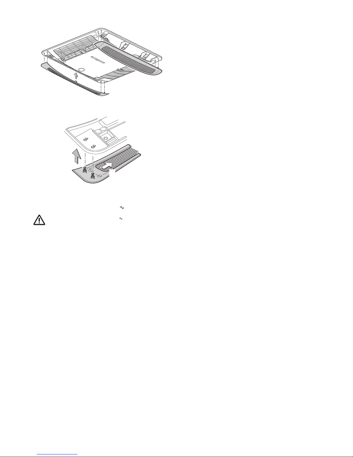
Einsetzen der Paneele in den Luftverteiler small
Bild 31
1
2
Bild 32
Elektrischer Anschluss 230 V
Der elektrische Anschluss 230 V darf nur vom Fach-
mann (in Deutschland z. B. nach VDE 0100, Teil 721
oder IEC 60364-7-721) durchgeführt werden. Die hier abgedruckten Hinweise sind keine Aufforderung an Laien, den
elektrischen Anschluss herzustellen, sondern dienen dem von
Ihnen beauftragten Fachmann als zusätzliche Information!
Das zum Anschlusspunkt verlegte Netzkabel anschließen.
Alle Kabel müssen mit Schellen gesichert werden!
Für Wartungs- bzw. Reparaturarbeiten muss fahrzeugseitig
eine Trennvorrichtung zur allpoligen Trennung vom Netz mit
mindestens 3,5 mm Kontaktabstand vorhanden sein.
Funktionsprüfung /
Halterung für die Fernbedienung
Die Halterung für die Fernbedienung am gewünschten Platz
befestigen.
Abschließend müssen gemäß der Ge brauchsanweisung
sämtliche Funktionen des Gerätes geprüft werden.
Der Einbauer muss nach dem Einbau der Anlage prüfen, dass
die Kondensatabläufe frei sind.
Die Gebrauchsanweisung ist dem Fahrzeughalter
auszuhändigen.

15
EN
Aventa compact
Safety instructions
Only competent and trained persons
(experts) may install, repair or perform
the function check on the Truma product in
accordance with the installation and operating instructions and the currently accepted
technical regulations. Experts are persons
who, based on their specialist instruction and
training, their knowledge and experience with
Truma products and the relevant standards,
can carry out the necessary work properly and
identify potential hazards.
The appliance must be installed in accordance
with the national installation regulations.
This appliance may be used by children from
8years old and by persons with reduced physical, sensory or mental capabilities or with a
lack of experience and knowledge only if they
are supervised or have been instructed in the
safe use of the appliance and understand the
resulting risks.
Children must not be allowed to play with the
appliance.
To avoid transportation damage, the appliance
may only be dispatched if the Truma Service
Centre has been consulted beforehand.
When transporting on trailers with lowered
drawbars, the openings on the rear side of the
air conditioning system must be taped up in
order to prevent water from entering.
The power supply must be disconnected
from the mains (all poles) before opening the
housing.
The appliance fuses and connection cables
must only be replaced by experts.
The 230 V, T 5 A H (slow) appliance fuse can
be found on the electronic control unit in the
appliance and must always be replaced with
an identical fuse.
Only original Truma parts, spare parts and
accessories may be used.
Symbols used
The appliance must only be installed and repaired
by an expert.
Symbol indicates possible hazards.
Note containing information and tips.
The appliance is not accessible to the general public
You can also download the installation and operating
instructions from our web site. Use the following link
for the respective instructions:
https://www.truma.com/int/en/service/downloads.html
Table of contents
Symbols used ...................................................................... 15
Safety instructions .......................................................... 15
Notes on using air conditioning systems .................... 16
Operating instructions
Remote control .................................................................... 17
Start-up ............................................................................... 18
Switching on ....................................................................... 18
Mode ................................................................................... 18
Fan ....................................................................................... 18
Sleep function ..................................................................... 18
Switching off ....................................................................... 18
Time ..................................................................................... 18
Timer ON / OFF ................................................................... 18
* Ambient lighting ............................................................... 18
Reset ................................................................................... 18
Resend ................................................................................ 18
Setup ................................................................................... 19
IR receiver and manual on / off ........................................... 19
IR receiver / function display ............................................... 19
Red LED illuminated ............................................................ 19
Air distribution ..................................................................... 19
IR remote control battery change ....................................... 19
Disposal ............................................................................. 19
Maintenance ..................................................................... 19
Disposal ............................................................................. 19
Accessories ....................................................................... 20
Troubleshooting ............................................................... 20
Technical data ................................................................... 21
Installation dimensions (in mm) .......................................... 21
Clearance around the air conditioning system ................... 21
Air inlets / outlets ................................................................ 21
Condensation traps ............................................................. 22
Manufacturer’s Warranty
(European Union) .............................................................. 22
Installation instructions
Scope of delivery ............................................................. 23
Accessories for installation (optional) ........................... 23
Intended use ..................................................................... 24
Selecting a location ......................................................... 24
Cut-out installation 400 x 400 ....................................... 24
Installation with new cut-out ........................................ 24
Preparation for power cable connection and control
panelcable .......................................................................... 25
Securing the appliance ....................................................... 25
Use of roof thickness adapters ........................................... 26
Insert the filter into the air distributor ................................ 26
Insert the panels into the air distributor small .................... 27
230 V electrical connection
............................................ 27
Function check / remote control mounting ........................ 27

16
EN
In particular, the following will render warranty
and guarantee claims void and lead to exemption from liability claims:
– Modifications to the appliance (including
accessories),
– Using replacement and accessory parts oth-
er than original Truma parts,
– Failure to follow the installation and operat-
ing instructions.
The appliance’s operating permit, and consequently also the vehicle’s operating permit in
some countries, are also rendered void.
The refrigerant circuit contains R 407C refrigerant and must only be opened in the
factory.
The air inlets / outlets at the external unit and
the air distributor must not be obstructed
under any circumstances. This is essential in
order to ensure that your appliance operates
correctly.
To prevent damage to the compressor, the
appliance may only be operated with a maximum angle of 8 %.
Do not operate the appliance in cooling mode
for long periods with the vehicle at an angle,
since the condensation that is produced may
not be able to run away and may penetrate
the vehicle under unfavourable circumstances.
In order to ensure that the equipment works
perfectly and to avoid damage, only power
supply sources with a purely sinusoidal waveform (e.g. generator) and without voltage
peaks may be used.
Operation of the air conditioning system is only permitted on a primary voltage source.
When the vehicle is being cleaned it must be
ensured that no water gets into the appliance
when spraying with a high-pressure cleaner,
for example (do not spray directly into the
openings of the appliance).
Hot cleaners and steam cleaners must not be
used.
The condensation traps must be clear at all
times during operation.
Notes on using air conditioning systems
You should still check whether the camp site
has adequate fuse protection (min. 4 A) before
starting the equipment up.
Park the vehicle in the shade if possible.
Darkening with blinds reduces the amount of
heat insolation.
Clean your roof at regular intervals (a dirty roof
heats up more than a clean roof).
The vehicle must be properly ventilated before
starting the equipment in order to remove accumulated warm air from the vehicle.
In order to obtain a healthy room climate, the
difference between the inside and outside
temperatures should not be too great. The
recirculated air is cleaned and dehumidified
during operation. A pleasant room climate is
produced by drying the moist air, even with
small temperature differences.
Keep all doors and windows closed when in
cooling mode so that no condensation forms
on the air distributor.
For faster cooling:
– Set fan level to high,
– Set front / rear air distribution to centre
position,
– Set floor / ceiling air distribution to ceiling.
The remote control should no longer be used
when operating the air conditioning system
in conjunction with the Truma CP plus controlpanel and/or a Truma iNet Box (App).
You can use the Truma App for remotecontrol.

17
EN
Operating instructions can be viewed in offline mode
with a mobile device and the Truma App. Download the
operating instructions when you have a WiFi connection and
save them on your mobile device.
Remote control
Figure 1
Sleep function
Ultra-quiet fan operation by
reducing the speed of both fans
* Ambient lighting
The lighting is dimmed by pressing
and holding down the button.
Pressing it again deactivates
or activates the lighting.
Mode
Mode selection button
– Cooling
–
Automatic
– Circulated air
Temperature selection buttons
16 – 31 °C
In 1 °C steps
On / O switch
Reset
Resets the remote control
to the factory settings.
Fan level
– low
– medium
– high
Resend
Retransmit data
T
ime selection
button
Time setting
Setting for clock time
and timer
T
imer selection button
Switch-on / switch-o time
can be set up to 24 hours in advance
*
No function in the case of air distributor small
Timer
On/O time
Cooling
Setup
Resend /
data tr
ansmission
Circulated
air
Fan level
Sleep function
Temperature
Time
Automatic
mode
Setup button
Tuning the remote control
and the IR receiver
Operating instructions
The symbols shown in the display become visible depending on the setting

18
EN
Start-up
Before switching on, be sure to check that the camp site has
adequate power supply fusing (230 V).
In order to prevent the power cable of the recreational vehicle from overheating (minimum cross-section
3x2.5 mm²) the cable drum must be fully unwound.
The remote control must always be pointed at the infrared receiver in order to perform the individual switching commands.
Before switching on for the first time, the remote control must
be tuned to the IR receiver.
– Insert batteries (pay attention to polarity)
– Setup symbol flashes
(if symbol does not flash, perform Reset)
– Point remote control at IR receiver
– Press Setup button and hold down
– When the red LED on the IR receiver starts to flash, release
the Setup button.
The remote control is tuned to the IR receiver, the Setup symbol goes off and the air conditioning system starts in circulated air mode, at low fan level and with no timer set.
Switching on
Switch on the air conditioning system using the “On / Off
switch” of the remote control. The last selected settings are
taken over.
The circulated air fan runs after switching on. The compressor switches itself on after no more than 3 minutes,
and the blue LED flashes.
Temperature
If necessary, use the “Temperature selection buttons” to
set the required room temperature with “+” and “–”.
Mode
Select the required operating mode by pressing the “MODE”
button one or more times.
– Cooling
– Automatic
– Circulated air
When the room temperature that was selected using the remote control is reached in cooling mode, the compressor
switches off and the blue LED in the IR receiver goes off. The
circulated air fan continues to run in order to provide ventilation. If the room temperature setting is exceeded, the appliance automatically reverts to cooling mode.
. If the air humidity in the vehicle is extremely high at
the beginning of the cooling procedure, moisture can
build up on the underside of the air distributor. The doors and
windows should therefore be kept closed and the highest fan
level selected.
In automatic mode, the fan level is selected automatically
depending on the room temperature.
In circulated air mode, the interior air is recirculated and
cleaned by the filters / panels No LED’s illuminate in the
IR receiver.
Fan
Select the required fan level by pressing the “Fan level” but-
ton one or more times.
Fan level (not functional in automatic mode):
– low
– medium
– high
Sleep function
In “Sleep function” the internal and external fans operate at
slow speed and are therefore extremely quiet.
Switching off
To switch off, press the “On / Off switch” on the remote
control. The remote control and the appliance are switched off.
* The light can still be switched on and off using the
“Ambient lighting” button.
* No function in the case of air distributor small
The blue LED flashes when the air conditioning system
is switched back on. The circulated air fan runs, and the
compressor switches on after no more than 3 minutes.
Time
Press the “Time selection button” and set the current time
using the “Time setting” buttons.
The time is always shown on the display (exception with
ON /OFF timer).
The time must be reset after changing the batteries or after a
daylight saving time change.
Timer ON / OFF
The On / Off time of the air conditioning system can be set
in advance for a minimum of 15 minutes to a maximum of
24 hours, starting from the current time, using the integrated
timer.
The appliance must be switched on using the remote control
in order to program it.
Set required operating mode and room temperature.
Then select TIMER ON or TIMER OFF using the “TIMER
selection buttons”. Set the required On / Off time using
the “Time setting” buttons (15 minutes to 24 hours) and
confirm with TIMER ON or TIMER OFF.
Pressing the relevant timer button again deactivates the timer
function.
* Ambient lighting
Irrespective of whether the air conditioning system is operating, the lighting in the air distributor can be switched on or
off by pressing the “Ambient lighting” button. The lighting
is dimmed by pressing and holding down the “Ambient
lighting” button. The previous setting is activated when it is
switched on again.
* No function in the case of air distributor small
Reset
Resets the settings of the remote control to the factory settings when pressed using a ballpoint pen, for example. Setup
symbol flashes.
Resend
The previous settings are resent.

19
EN
Setup
Tune the remote control to the air conditioning system that is
going to be operated.
IR receiver and manual on / off
There is an additional pushbutton on the IR receiver (m), with
which the unit can also be switched on and off without the
remote control (e.g. with a ballpoint pen).
If the unit is switched on using this pushbutton, the system is
automatically reset to the factory settings (automatic mode,
22 °C).
IR receiver / function display
LED 2
LED 1
m
Figure 2
LED 1 blue – illuminated – (cooling mode)
LED 1 blue – flashing – (cooling mode compressor start-up)
LED 2 red – flashing – (data transfer in progress)
LED 2 red – illuminated – (fault)
LED 1 and LED 2 illuminated (230 V interrupted
,
compressor switches off)
Red LED illuminated
The appliance is indicating a fault. Switch the appliance off,
wait for a short time and switch on again. If red light stays on,
contact Truma Service.
Air distribution
Right / left
There are two individually adjustable air outlets at the front
and rear.
Front / rear
The air flow can be metered between the front and rear areas
of the vehicle.
Ceiling / floor
The air flow can be directed from the ceiling to the floor.
Aventa
Right / leftRight / left
Right / left
Right / left
IR receiver /
function display
Front / rear
Ceiling /
floor
Ceiling /
floor
Front
Front
RearRear
Figure 3
IR remote control battery change
Only use micro-batteries that will not leak, type LR 3, AM4,
AAA, MN 2400 (1.5 V).
The battery compartment is on the back of the remote control.
When inserting new batteries, make sure
the positive / negative terminals are connected correctly.
Empty, used batteries can leak
and damage the remote control!
Remove the batteries if the remote control is not being used for a long period of
time.
Figure 4
No warranty is given for damage caused by leaking
batteries.
Disposal
Neither the remote control nor the batteries may be
disposed of with domestic refuse, instead they must be
sent for recycling separately via a collection point. By
doing this you are contributing towards reuse and recycling.
The tuning between the remote control and the air conditioning system is retained if the batteries are removed.
Maintenance
Maintenance, repairs and cleaning must not be done by
children.
Carry out filter changes depending on the amount of use, but
at least every 12 months.
On the air distributor small, remove the panels and clean under clear / lukewarm water.
Never operate the air conditioning system without a filter /
panels. This can lead to loss of power. Keep the air inlets /
outlets and the condensation traps on the roof free of obstructions such as leaves at all times. The air conditioning system
should only be cleaned with a soft, damp cloth.
Disposal
The appliance must be disposed of in accordance with the administrative regulations of the respective country in which it is
used. National regulations and laws (in Germany, for example,
the End-of-life Vehicle Regulation) must be observed.
The relevant regulations must be observed in other countries.

20
EN
Troubleshooting
Fault Cause / Remedy
Appliance not cooling – Thawing procedure in progress
– Remote control temperature
setting reached or too high
Appliance providing insufficient cooling or no
cooling at all
– Filter / panels dirty, replace
filter/clean panels
– External air routes soiled /
blocked
Moisture on underside
of air distributor
– Close windows and doors and
select high fan level
Water dripping out of
air distributor
– Condensation trap on external
unit blocked
– Seal between appliance and
roof not intact
– System at too much of an angle
Remote control
not working
– Check batteries in remote con-
trol and replace if necessary
Appliance not reacting to remote control
commands
– Check whether there are ob-
structions between the remote
control and the IR receiver
– Is the remote control tuned to
the IR receiver / Tune remote
control to IR receiver.
Compressor switches
off and back on again
after approx. 3 minutes
– Voltage drop at 230V
power
supply / check 230V
power
supply
If these actions do not remedy the problem, please contact Truma Service.
Accessories
Aventa air filter kit, 2 pcs
for air distributor, not for air distributor small
(Part. No. 40091-16800)
Figure 5
Truma CP plus
Truma CP plus digital control panel with automatic climate
control for the iNet-capable Truma heaters Combi and
Truma air conditioning systems Aventa eco, Aventa comfort
(from serial number 24084022 – 04/2013), Saphir comfort RC
and Saphir compact (from serial number 23091001 – 04/2012)
– The automatic climate control function automatically con-
trols the heater and the air conditioning system until the
required temperature is reached in the vehicle.
– Can be extended with the TrumaiNet Box. With this, all
TIN bus-capable Truma appliances can also be controlled
via the Truma App
Figure 6
Truma iNet Box
The Truma iNet Box for simple networking and control of
Truma appliances with a smartphone or tablet computer using
the app.
– Simple installation and start-up via the Truma App
– Can be extended with the update function, which ensures
that it is always up to date
Figure 7

21
EN
Clearance around the air conditioning system
The clearance around the external unit must be 20 mm at
the front and 50 mm at the side. At least 20 mm of clearance
must be left at the rear. Truma recommends clearance of
50 mm so that the exhaust air can blow out freely.
50
560
50
50
785
20
20
Figure 10
The clearance around the air distributor must allow the air
to blow out without obstructions. The side clearance must be
at least 40 mm (not in the case of the air distributor small).
The pivoting range of flaps and doors must be taken into
consideration.
400
670
380
78
523
400
350
40
40
46
FRONT
Figure 11 – Air distributor
400
556
380
50
496
400
350
46
FRONT
Figure 11 a – air distributor small
Air inlets / outlets
Figure 12
Technical data
Determined on the basis of EN 14511 or Truma test conditions
Power supply
230 V – 240 V
, 50 Hz
Power consumption
Cooling: 2.8 A
Starting current
20 A (150 ms)
Cooling power
1.7 kW (T35 / T35)
Air volume flow
max. 370 m³/h
Usage limits
+16 °C to 40 °C
Maximum angle during operation
8 %
Weight
27.5 kg plus installation materials
Dimensions (W x H x D)
External: 560 x 265 x 785 mm
Internal: 523 x 46 x 670 mm (air distributor)
Internal: 496 x 46 x 556 mm (air distributor small)
Refrigerant
R 407C / 0.36 kg
Contains fluorinated greenhouse gases covered by the Kyoto
Protocol. Hermetically sealed.
Global Warming Potential (GWP)
1774
CO equivalent
638.6 kg
Subject to technical changes.
Installation dimensions (in mm)
670
556*
785
265
46
25 - 110
Figure 8
400
(380)
400
(350)
523 / 496*
192
(212)
310
560
Figure 9
*air distributor small

22
EN
2. Warranty exclusions
No warranty claim shall be applicable under the following
circumstances:
– Improper, unsuitable, faulty or negligent use and any use
that is not compliant with the intended purpose
– Improper installation, assembly or commissioning, contrary
to operating or installation instructions
– Improper operation or operation contrary to operating or
installation instructions, particularly any disregard for maintenance, care or warning notes,
– Instances where installations, repairs or any other proce-
dures have been conducted by non-authorised parties
– Consumable materials and parts which are subject to natu-
ral wear and tear
– Installation of replacement, supplementary or accessory
parts that are not original manufacturer’s parts or which
have not been approved by the manufacturer. This applies
in particular if the appliance is subject to networked control,
if the control units or the software have not been approved
by Truma or if the Truma control unit (e.g. Truma CP plus
or Truma iNet Box) has not been exclusively used for controlling Truma appliances or appliances approved by Truma.
– As a consequence of damage arising from foreign sub-
stances (e.g. oil, or plasticisers in the gas), chemical or
electrochemical influences in the water, or cases when the
appliance has come into contact with unsuitable substances (e.g. chemical products, flammable substances or unsuitable cleaning agents)
– Damage caused by abnormal environmental or unsuitable
operating conditions
– Damage caused by force majeure or natural disasters or
any other influences not within Truma’s responsibility
– Damage resulting from improper transport
– End customer’s or third-party modifications of the appli-
ance, including any replacement, supplementary or acces-
sory parts, or installation of the same, especially concerning
the exhaust gas system or the cowl.
3. Making a warranty claim
The warranty must be claimed with an authorised service partner or at the Truma Service Centre. All the relevant addresses
and phone numbers can be found at www. Truma.com, in the
“Service” section.
The Manufacturer’s address is:
Truma Gerätetechnik GmbH & Co. KG
Truma Servicezentrum
Wernher-von- Braun-Straße 12
85640 Putzbrunn, Germany
To ensure a smooth procedure, we would be grateful if you
could have the following details ready before contacting us:
– Detailed description of the defect
– Serial number of the appliance
– Date of purchase
The authorised service partner or the Truma Service Centre
will then specify the further procedure. To avoid transport
damage, the affected appliance must only be shipped by prior
arrangement with the authorised service partner or the Truma
Service Centre.
If the warranty claim is recognised by the Manufacturer, then
the transport expenses shall be borne by the same. If no
warranty claim is applicable, the Consumer will be notified
accordingly and any repair and transport expenses shall then
be the Consumer’s liability. We ask you not to send in an appliance without prior arrangement.
Condensation traps
The condensation is led away via the roof of the vehicle.
Figure 13
Subject to technical changes.
Manufacturer’s Warranty
(European Union)
1. Scope of Manufacturer’s Warranty
As the Manufacturer of the appliance, Truma undertakes a
warranty towards the Consumer that covers any material
and/or manufacturing defects of the appliance.
This Warranty is applicable in EU member states as well as
in Iceland, Norway, Switzerland and Turkey. A Consumer is
the natural person who was the first one to purchase the
appliance from the Manufacturer, OEM or dealer and who
neither resold the appliance in a commercial or self-employed
professional capacity nor installed it for a third party in such a
capacity.
The Manufacturer’s Warranty covers any of the aforementioned defects that occur within 24 months upon concluding
the purchase agreement between the seller and the Consumer.
The Manufacturer or an authorised service partner undertakes
to remedy such defects through subsequent fulfilment, i.e.
at its discretion either by repairing or replacing the defective
item. Defective parts shall become the property of the Manufacturer or the authorised service partner. If the appliance is no
longer manufactured at the time of defect notification and if
replacement delivery has been opted for, then the manufacturer may deliver a similar product.
If the Manufacturer remedies a defect under its Warranty
commitment, the term of the Warranty shall not start again
with regard to the repaired or replaced parts; rather, the original warranty period shall continue to be applicable to the
appliance. Only the Manufacturer itself and an authorised service partner shall be entitled to conduct a warranty job. Any
costs that occur in the event of a warranty claim shall be settled directly between the authorised service partner and the
Manufacturer. The Warranty does not cover additional costs
arising from complicated removal or installation jobs on the
appliance (e.g. dismantling of furnishings or parts of the vehicle body), and neither does it cover travel expenses incurred
by the authorised service partner or the Manufacturer.
No further-reaching claims shall be permitted, especially damage claims presented by the Consumer or third parties. This
shall not affect the provisions of the German Product Liability
Act (Produkthaftungsgesetz).
The voluntary manufacturer’s warranty does not affect the
consumer’s legally valid claims for defects against the seller in
the relevant country of purchase. In individual countries there
may be warranties that can be issued by the relevant dealer
(official distributor, Truma Partner). In such cases the warranty
can be implemented directly through the dealer from whom
the Consumer bought the appliance. The warranty regulations
of the country in which the appliance was purchased by the
Consumer for the first time shall also be applicable.

23
EN
Installation instructions
Figure 14
Only competent and trained staff (experts) are permitted
to install and repair the Truma product and to carry out the
function test, at the same time observing the installation
and operating instructions and the currently recognised
technical regulations. Experts are persons who, based on
their specialist instruction and training, their knowledge and
experience with Truma products and the relevant standards,
can carry out the necessary work properly and identify
potential hazards.
Scope of delivery
External unit:
– 1 Aventa compact
– 2 brackets
– 4 screws M6 x 70 coated with screw sealant
– 6 screws M6 x 12 coated with screw sealant
– 1 base ring
– 2 roof thickness adapters (each 10 mm)
– 1 remote control with mounting
– 2 screws 2.9 x 16 for mounting
– 2 AAA batteries
– 1 set of operating and installation instructions
– 1 installation template
– 3 Wago clamps
– 1 control panel cable
Air distributor (to be ordered separately):
– 1 air distributor, fully assembled or
– 1 air distributor small, fully assembled
Accessories for installation (optional)
Roof thickness adapter 10 mm, 1 piece (part no. 40091-16900)
Figure 15
Aventa sealing frame (part no. 40091-19500)
Recommended for optimum sealing when retrofitting in
vehicles with 400 x 400 mm cut-out.
Figure 16
Levelling frame installation kit for van
Figure 16 a
PSA adapter frame kit for van
Figure 16 b
Covering tape
cream (part no. 40091-31200)
grey (part no. 40091-31300)
For compensating for a gap of up to 5 mm between air
distributor and roof.
l ~ 2,36 m
Figure 17
Adapter 12 V for lighting the air distributor
not for air distributor small
1 piece (part no. 40091-33000).
Figure 18

24
EN
Intended use
This appliance has been designed for installation in motor
homes and caravans and is intended for private use.
Selecting a location
Once the roof-mounted air conditioning system has
been installed, any nearby exhaust cowl must extend
at least 10 cm above the air conditioning system. The exhaust
cowl must be extended if necessary (pay attention to the
heater manufacturer’s specifications).
The roof of the vehicle (roof thicknesses of 25 to 110 mm)
must be level and smooth.
Three installation options are available:
– The cut-out must be a new cut-out (350 x 380 mm)
– Cut-out of an existing roof hatch (400 x 400 mm) without a
sealing frame (accessory).
– Cut-out of an existing roof hatch (400 x 400 mm) with a
sealing frame (accessory). The installation instructions are
included with the sealing frame.
Attention must always be paid to the following points:
– The appliance should be installed as close as possible to the
centre of the vehicle.
– Check that no obstructions are present that will hinder
installation.
– There may be electrical cables running between the interior
and the exterior of the roof. Disconnect all voltage sources
before starting the work (all poles).
– The roof load must not be exceeded (see vehicle manufac-
turer’s specifications).
– Check the interior installation site for obstructions.
– A wooden reinforcing frame (min. 25 mm) must be installed
around the roof cut-out between the upper and lower sur-
faces of the roof. The insulation may have to be removed.
When the skylight with safety ventilation is replaced by
the air conditioning system, it must be ensured that the
safety ventilation is restored in another suitable location.
Control panel cable
To simplify subsequent installation of BUS appliances, feed
the control panel cable that is supplied in the accessory kit
together with the mains cable through the false ceiling.
Fix the free end of the control panel cable to a suitable place,
such as in a wardrobe, as a connection point.
Cut-out installation 400 x 400
For optimum sealing we recommend the use of the sealing
frame that is available as accessory (part no. 40091-19000).
For installation with a sealing frame, please refer to the installation instructions provided with the sealing frame.
Installation of the appliance with an existing roof hatch:
the cut-out must be 400 x 400 mm.
Remove existing roof hatch (make cut-out bigger if necessary).
Remove sealant residue and unevenness.
Fill in screw holes with body sealant.
4 0 0
4 0 0
Figure 19
For the other installation steps, please refer to “Preparation
for power cable connection and control panel cable”.
Installation with new cut-out
For vehicles without an existing cut-out:
required cut-out 350 x 380 mm.
Place template on installation location on vehicle, mark cutout (350 x 380 mm) and cut it out.
Mark the 4 holes (10 mm) for bracket attachment and drill
holes in the roof.
3 8 0
3 5 0
Figure 20

25
EN
Preparation for power cable connection and
control panelcable
Provide the lead-through to the connection point for the
mains cable and control panel cable, e.g. in the false ceiling.
FRONT
Figure 21
Move the appliance to the roof in a horizontal position and
insert into cut-out. The arrow should point in the direction of
travel.
Figure 22
Do not apply additional sealant between the air conditioning system and the roof.
If the appliance has been turned over or is not horizontal, you must wait for 2 hours before switching on the
device.
Push device forwards in cut-out as far as it will go.
Remove protective film from the appliance.
Route the power cable and control panel cable to the connection point (lengthen the mains cable with the provided Wago
clamps if necessary).
If the lighting of the air distributor is also going to be
optionally operated using 12 V, the 12 V adapter that is
available as an accessory must now be connected. The installation instructions are provided with the 12 V adapter.
FRONT
Figure 23
Securing the appliance
Screw the two brackets (marked with an arrow in the direction
of travel) to the appliance using the 4 provided M6x70screws
(with screw sealant).
Torque 1.8 Nm
If the roof is more than 50 mm thick, M6 screws
(length = roof thickness + 30 mm) with tensile strength of 8.8
must be used. The screws must be secured with low-strength
screw sealant (e.g. Loctite).
1.8 Nm
Figure 24
If the screws are used more than once (e.g. after removal)
they must be coated with low-strength screw sealant
again (e.g. Loctite) or the screws provided as spare parts used.

26
EN
Use of roof thickness adapters
Slide in the base ring (1) and, depending on the thickness of
the roof, the roof thickness adapters (2 or 2+3 included in
scope of delivery) for roof thicknesses of 25 to 50 mm into the
air distributor as far as they will go. If the roof is thicker, use
additional 10 mm roof thickness adapters (see Accessories).
Maximum roof thickness 110 mm
1
2
3
25 – 30 mm = 1
31 – 40 mm = 1+2
41 – 50 mm = 1+2+3
Figure 25
Securing the air distributor
Connect the cable from the air distributor and the control panel
cable to the control unit.
Figure 26
Screw air distributor (arrow in direction of travel) to brackets
with 6 screws M6 x 12 mm.
Torque 1.8 Nm. If the torque is too great, the air distributor
can be damaged or its function impaired.
The covering tape that is available as an accessory can
be used to compensate for the gap between the air dis-
tributor and the roof.
1.8 Nm
Figure 27
If the screws are used more than once (e.g. after removal) they must be coated with low-strength screw sealant
again (e.g. Loctite) or the screws provided as spare parts used.
Insert the filter into the air distributor
Insert filters into panels and attach to the air distributor.
Figure 28
Figure 29
Figure 30

27
EN
Insert the panels into the air distributor small
Figure 31
1
2
Figure 32
230 V electrical connection
The 230 V electrical connection must always be made
by an expert (in Germany for example in accordance
with VDE 0100, part 721 or IEC60364-7-721). These instructions are intended only as additional information for a qualified electrician; electrical work should not be carried out by
unqualified persons.
Connect the mains cable that has been routed to the connecting point.
All cables must be secured with clamps!
An insulating device for providing all-pole insulation from
the mains with contact clearance of at least 3.5 mm must be
provided at the vehicle end for carrying out maintenance and
repair work.
Function check / remote control mounting
Attach the mounting for the remote control in the required
location.
All appliance functions must subsequently be tested as
described in the operating instructions.
The installer must check that the condensation traps are clear
after installing the system.
The operating instructions must be handed over to the vehicle
owner.

28
FR
Aventa compact
Informations concernant la sécurité
Seul du personnel spécialisé et formé a
le droit de monter les produits Truma,
de les réparer et d’effectuer la vérification du
fonctionnement en respectant les instructions
de montage et le mode d’emploi ainsi que les
règles reconnues de la technique. On entend
par personnel spécialisé des personnes qui, en
raison de leur formation professionnelle initiale
et de formations ultérieures, de leurs connaissances et expériences avec les produits Truma
et les normes en vigueur, sont en mesure d’effectuer correctement les travaux nécessaires
et de reconnaître les dangers possibles.
L’appareil doit être installé en suivant les
consignes d’installation nationales.
Cet appareil peut être utilisé par des enfants
à partir de 8 ans ainsi que des personnes aux
capacités physiques, sensorielles ou mentales
restreintes ou bien manquant d’expérience et
de connaissances à condition d’être sous surveillance ou d’avoir été instruits sur l’utilisation
sûre de l’appareil et de comprendre les risques
en résultant.
Les enfants ne doivent pas jouer avec l’appareil.
Afin d’éviter les dommages dus au transport,
l’appareil doit être envoyé seulement après
accord du centre de SAV Truma.
Pour éviter une entrée d’eau en cas de transport sur une remorque avec timon abaissé, les
ouvertures sur le côté arrière du système de
climatisation doivent être bouchées avec du
ruban adhésif.
Avant d’ouvrir le boîtier, la tension doit être
coupée du secteur sur tous les pôles.
Seul un spécialiste est autorisé à remplacer les
fusibles de l’appareil et les conduites de raccordement au secteur.
Le fusible de l’appareil 230 V, T 5 A H (à action
retardée) se trouve sur la commande électronique de l’appareil; il doit être remplacé uniquement par un fusible similaire.
Symboles utilisés
Le montage et la réparation de l'appareil doivent être effectués uniquement par du personnel spécialisé.
Ce symbole indique des risques possibles.
Remarque avec informations et conseils.
L'appareil n'est pas accessible auprès du grand public
Vous pouvez également télécharger les instructions de montage / le mode d'emploi depuis notre site Web. Vous trouverez
le document correspondant sous le lien suivant:
https://www.truma.com/fr/fr/sav/telechargements.html
Table des matières
Symboles utilisés ................................................................ 28
Informations concernant la sécurité ............................ 28
Remarques sur l'utilisation de systèmes de
climatisation ..................................................................... 29
Mode d’emploi
Télécommande .................................................................... 30
Mise en service ................................................................... 31
Mise en marche .................................................................. 31
Mode ................................................................................... 31
Ventilateur ........................................................................... 31
Fonction Sommeil ............................................................... 31
Arrêt .................................................................................... 31
Heure ................................................................................... 31
Timer ON / OFF ................................................................... 31
* Éclairage d’ambiance ....................................................... 31
Reset ................................................................................... 31
Resend ................................................................................ 31
Setup ................................................................................... 32
Récepteur IR et marche/arrêt manuel ............................... 32
Récepteur IR / affichage de fonctions ................................ 32
La LED rouge s’allume ........................................................ 32
Distribution d’air .................................................................. 32
Remplacement des piles de la télécommande IR .............. 32
Mise au rebut .................................................................... 32
Maintenance ..................................................................... 32
Mise au rebut .................................................................... 32
Accessoires ....................................................................... 33
Recherche de pannes ...................................................... 33
Caractéristiques techniques .......................................... 34
Dimensions pour le montage (dimensions en mm) ............ 34
Espaces libres autour du système de climatisation ............ 34
Entrées d’air / sorties d’air ................................................... 34
Écoulements d’eau de condensation .................................. 35
Déclaration de garantie du fabricant
(Union européenne) ......................................................... 35
Instructions de montage
Volume de livraison ......................................................... 36
Accessoires pour le montage (en option) ...................... 36
Utilisation .......................................................................... 37
Choix de l’emplacement ................................................. 37
Montage découpe 400 x 400 ......................................... 37
Montage avec découpe dans une surface encore
pleine .................................................................................. 37
Préparation connexion câble d’alimentation et câble
depiècedecommande ...................................................... 38
Fixation de l’appareil ........................................................... 38
Mise en place des adaptateurs d’épaisseur detoit ............ 39
Mise en place des filtres dans le distributeur d’air ............ 40
Mise en place des panneaux dans le distributeur d’air small .. 40
Connexion électrique 230 V
............................................ 40
Vérification du fonctionnement /
support pour la télécommande .......................................... 40

29
FR
Utiliser seulement des pièces originales, de
remplacement et d’accessoires Truma.
Les actions suivantes en particulier invalident
les droits à garantie et entraînent l’exclusion
de toute demande de réparation du préjudice
subi :
– modifications apportées à l’appareil (y com-
pris accessoires) ;
– utilisation de pièces de rechange et ac-
cessoires autres que des pièces originales
Truma;
– non-respect des instructions de montage et
du mode d’emploi.
En outre, l’autorisation d’utiliser l’appareil
est annulée et entraîne dans de nombreux
pays l’annulation de l’autorisation pour tout le
véhicule.
Le circuit de froid contient le réfrigérant R407C;
il doit être ouvert uniquement en usine.
Les entrées d’air / sorties d’air de l’unité extérieure et sur le distributeur d’air ne doivent
en aucun cas être entravées. Veuillez en tenir
compte pour assurer un fonctionnement irréprochable de votre appareil.
Afin d’éviter des détériorations sur le compresseur, ne pas utiliser l’appareil sur une position
inclinée de plus de 8 %.
Ne pas effectuer de mode de rafraîchissement
prolongé en position inclinée, l’eau de condensation produite ne pouvant le cas échéant pas
s’écouler et risquant dans un cas défavorable
de parvenir à l’intérieur du véhicule.
Pour un fonctionnement irréprochable, et
pour éviter les dommages, il faut pour l’alimentation en tension utiliser uniquement des
sources au tracé sinusoïdal pur (par exemple
générateur), sans pics de tension.
Le fonctionnement du système de climatisation est autorisé seulement sur une source de
tension primaire.
S’assurer lors du nettoyage du véhicule que
de l’eau ne parvient pas dans l’appareil avec
par exemple un système de nettoyage haute
pression (par exemple ne pas pulvériser directement dans les ouvertures de l’appareil).
L’emploi / l’utilisation d’appareils de nettoyage à
eau chaude et à vapeur n’est pas admissible.
Les écoulements d’eau de condensation
doivent toujours être libres pendant le
fonctionnement.
Remarques sur l'utilisation de systèmes
de climatisation
Avant la mise en service, vérifiez si le camping
offre une protection suffisante (au moins4 A).
Parquez votre véhicule dans la mesure du possible à l’ombre.
L’occultation avec des stores réduit le rayonnement de chaleur.
Nettoyez régulièrement votre toit (les toits
sales chauffent plus vite).
Aérez à fond avant de faire fonctionner l’appareil afin d’évacuer hors du véhicule l’air chaud
accumulé.
Pour obtenir un climat ambiant sain, la différence entre la température intérieure choisie et
la température extérieure ne doit pas être trop
importante. L’air mis en circulation est nettoyé
et séché pendant le fonctionnement. Même
en cas de faibles différences de température,
le séchage de l’air humide et lourd crée un climat ambiant agréable.
Pendant le mode de refroidissement, garder
toutes les portes et fenêtres fermées afin
d’éviter toute formation d’eau de condensation sur le distributeur d’air.
Pour un refroidissement plus rapide:
– palier de ventilateur réglé sur «haut»,
– distribution d’air avant / arrière sur la posi-
tion du milieu,
– régler la distribution d’air plancher / plafond
sur «plafond».
Ne plus utiliser la télécommande en cas de
fonctionnement du système de climatisation en liaison avec la pièce de commande
Truma CP plus et / ou une Truma iNet Box(app).
Vous pouvez utiliser la Truma App pour la commande à distance.
 Loading...