

Page 1

* Assembly Guide & Warranty Card Included
XC400 ELLIPTICAL
OWNER’S MANUAL
Revision 091418
Page 2

XC400 ELLIPTICAL OWNERS MANUAL
IMPORTANT:
All Products shown are prototype. Actual product delivered may vary.
Product specifications, features & software are subject to change without notice.
For the most up to date owner’s manual please visit www.truefitness.com.
For documents in additional languages please visit www.truefitness.com/document-library/29/international-manuals
IMPORTANTE:
Todos los productos mostrados son prototipos. La realidad el producto suministrado puede diferir.
Especificaciones de productos, características y software están sujetas a cambios sin previo aviso.
Para la más actualizada de este manual del propietario, por favor visite www.truefitness.com
Para los documentos en otros idiomas, por favor visite www.truefitness.com/document-library/29/international-manuals
IMPORTANT:
Tous les produits présentés sont prototype. Le produit réel livré peut varier.
Spécifications du produit, caractéristiques et logiciels sont sujettes à modification sans préavis.
Pour la plus à jour le manuel du propriétaire s'il vous plaît visitez www.truefitness.com.
Pour
documents dans des langues supplémentaires, veuillez www.truefitness.com/document-library/29/international-manuals de visite
重要提示:
显示所有产品的原型。实际交付的产品可能有所不同
品规格,功能和软件如有更改,恕不另行通知
产
迄今为止
对于其他语言的文档,请访问www.truefitness.com/document-library/29/international-manuals
对于大多数的使用说明书,请访问www.truefitness.com
:مﺎھ
ﻊﯾﻣﺟ تﺎﺟﺗﻧﻣﻟا ﻲھ ﺔﺿورﻌﻣﻟا جذوﻣﻧﻟا .فﻠﺗﺧﺗ دﻗ ﻲﻠﻌﻔﻟا ﺞﺗﻧﻣﻟا .ﺎﮭﻣﯾﻠﺳﺗ
و ،ﺞﺗﻧﻣﻟا تﺎﻔﺻاوﻣ ﺞﻣارﺑﻟاو تازﯾﻣﻟارﯾﯾﻐﺗﻠﻟ ﺔﻠﺑﺎﻗ رﺎﻌﺷإ نود.
ﻟ لﺻﯾ ﺎﻣ مظﻌﻣنﻵا ﻰﺗﺣ كﻟﺎﻣﻟا لﯾﻟد ةرﺎﯾز ﻰﺟرﯾ
www.truefitness.com.
تادﻧﺗﺳﻣﻠﻟ تﺎﻐﻟ ﻲﻓ ﻰﺟرﯾ ،ﺔﯾﻓﺎﺿإ ةرﺎﯾز
www.truefitness.com/document-library/29/international-manuals
WICHTIG:
Alle hier gezeigten Produkte sind Prototypen. Das tatsächliche Produkt ausgeliefert wird, kann variieren.
Produkt-Spezifikationen, Funktionen und Software können sich ohne vorherige Ankündigung ändern.
In den meisten Fällen bis zu Bedienungsanleitung Bisher besuchen Sie bitte www.truefitness.com.
Für Dokumente in weiteren Sprachen finden Sie unter www.truefitness.com/document-library/29/international-manuals
BELANGRIJK:
Alle getoonde producten zijn prototype. Daadwerkelijke product geleverd kan verschillen.
Product specificaties, eigenschappen & software zijn onderhevig aan verandering zonder kennisgeving.
Voor de meest actuele handleiding van de eigenaar kunt u terecht www.truefitness.com.
Voor documenten in andere talen kunt u terecht op www.truefitness.com/document-library/29/international-manuals
ВАЖНО:
Все товары указаны прототипа. Фактический продукт, поставляемый могут отличаться.
Технические характеристики, особенности и программного обеспечения могут быть изменены без предварительного
уведомления.
Для получения самой последней на сегодняшний день руководство по эксплуатации пожалуйста, посетите
www.truefitness.com
.Для документов на другие языки, пожалуйста, посетите www.truefitness.com/document-library/29/international-manuals
ruefitness.com / 800.426.6570 / 636.272.7100
T
Page 3

XC400 ELLIPTICAL OWNERS MANUAL
Frank Trulaske began TRUE Fitness over thirty-five year ago with the simple philosophy of delivering
superior fitness products, service and support. Today, TRUE is the global leader in premium fitness
equipment for the commercial and residential markets. Our goal is to be the leader in technology, innovation,
performance, safety and style. TRUE has received many awards for its product over the years and remains the
benchmark for the industry. Fitness facilities and consumers invest in TRUE products for their durable
commercial platforms used in all its products, both commercial and residential alike.
The proud manufacturing tradition of quality and the culture of innovation at TRUE have given rise to a full
line of extraordinary cardio and strength equipment. As a result, people all over the world are benefiting from
the TRUE experience. Innovation across the full product line has made TRUE successful and is a trademark of
the TRUE heritage. TRUE’s patented Heart Rate Control technology is just one of the remarkable ways we
deliver simple and superior performance every user can enjoy, and most importantly, use to achieve personal
health and fitness goals.
At the heart of our success is the relentless and systematic life testing of both our products and their
components. We have dedicated employees who understand our philosophy is to deliver the best products in
the world.
Our goal is to deliver the world’s best premium equipment for our customers’ health and fitness solutions.
Truefitness.com / 800.426.6570 / 636.272.7100
Page 4

XC400 ELLIPTICAL OWNERS MANUAL
Chapter 1: Safety Instructions
TABLE OF CONTENTS
Safety Instructions 1
Space Requirements 3
Grounding Instructions 4
Power Requirements 5
Warning Decals 6
Compliances 6
Chapter 2: Assembly Instructions
Pre Assembly Checklist 7
Elliptical Assembly Steps 8
Wiring Diagrams 19
Chapter 3: Product Overview
Chapter 4: Care & Maintenance
Care & Maintenance
Cleaning the Equipment
Other Scheduled Preventive Maintenance
Long Term Storage
:
25 Elliptical Overview
27
27
28
28
Chapter 5: Customer Service
Contacting Service
Contacting Sales
Reporting Freight Claims or Parts Damage
Chapter 6: Additional Information
Troubleshooting Guide
Chapter 7: Warranty Information
Warranty Information
Truefitness.com / 800.426.6570 / 636.272.7100
29
29
30
31
34
Page 5

CHAPTER 1: SAFETY INSTRUCTIONS
IMPORTANT SAFETY INSTRUCTIONS
SAVE THESE SAFETY INSTRUCTIONS
T
his elliptical is intended for a commercial or institutional setting. This owner’s manual should be accessible to all personal
trainers, staff members, and members.
WARNING: All EXERCISERS MUST READ ALL INSTRUCTIONS BEFORE USING THE ELLIPTICAL.
WARNING: Heart rate monitoring systems may be inaccurate for some individuals. Over-exercising may result in
serious injury or death. If you feel faint, stop exercising immediately.
WARNING: Equipment should be immediately taken out of use if it fails to work properly or when a warning is
presented electronically.
TRUE STRONGLY recommends seeing a physician for a complete medical exam before undertaking an exercise program,
particularly if the user has a family history of high blood pressure or heart disease, is over the age of 45, smokes, has high
cholesterol, is obese or has not exercised regularly in the past year. Additionally, TRUE recommends consulting a fitness
professional on the correct use of this product. If at any time while exercising the user experiences faintness, dizziness, pain or
shortness of breath, he or she must stop immediately.
WARNING: To reduce the risk of electrical shock, always unplug this TRUE product before cleaning or attempting any
maintenance activity. Do not handle the plug with wet hands.
WARNING: To reduce the risk of burns, fire, electric shock or injury, it is imperative to connect each product to a
properly grounded 110V electrical outlet. A risk of electrical shock may result from improper connection of the
equipment’s grounding conductor. Check with a qualified electrician if you are unsure about proper grounding
techniques. Do not modify the plug provided with this product. If it will not fit an electrical outlet, have a proper outlet
installed by a qualified electrician. Your TRUE Fitness product must be properly grounded to reduce risk of shock if the
elliptical malfunctions. Your elliptical may be equipped with an electrical cord, which includes an equipment grounding
conductor and a grounding plug. The plug must be inserted into an outlet that has been properly installed and grounded
in accordance with all local codes and ordinances. A temporary adapter cannot be used to connect this plug to a two-pole
receptacle in North America. If a properly grounded 15 amp outlet is not available, a qualified electrician must install
one.
WARNING: Do not move the equipment by lifting the console. Do not use the console as a handlebar during a workout.
WARNING: This product contains chemicals known to the state of California to cause cancer and birth defects or other
reproductive harm.
WARNING: Keep equipment stable on flat ground.
WARNING: Replace warning labels that may be worn, damaged or missing
WARNING: Replace any non-working or damaged components; remove the unit from service until repair is performed.
WARNING: To reduce the risk of burns, fire and electric shock or injury to persons, follow these instructions:
• This appliance should never be left unattended when plugged in.
• Do not use any type of extension cord with this product.
• Unplug it from the outlet when not in use and before any servicing.
• Do not operate the equipment while being covered with a blanket, plastic, or anything that insulates or stops
airflow.
ruefitness.com / 800.426.6570 / 636.272.7100 1
T
Page 6

CHAPTER 1: SAFETY INSTRUCTIONS
WARNING: Risk of personal injury-crushing hazard when elliptical is in operation - Keep feet, hands, and fingers
away from moving parts.
CAUTION:
• Health related injuries may result from incorrect or excessive use of exercise equipment.
• Do not use typing or web surfing features at excessive speeds. Always stabilize yourself by holding a stationary handl
w
hen using typing or web surfing features. (Varies by console option)
• Do not use the contact heart rate grips as a handlebar during a workout.
• Any changes or modifications to this equipment could void the product warranty.
• To avoid injury stand on the side rails before starting the elliptical.
• To disconnect, turn power OFF at the ON/OFF switch if applicable, then remove plug from electrical outlet.
• Never operate a TRUE product if it has a damaged power cord or electrical plug, or if it has been dropped, damaged, or
even partially immersed in water. Contact TRUE Customer Service.
• Your commercial elliptical is self-generated and does not require the use of an electrical outlet with the LED
console. Optional TFT or touch screen consoles require 110V AC input and 9V DC 1.5Amp output for consol
peration only.
o
• The batteries within self-generated equipment contain materials that are considered hazardous to the environment.
Federal law requires proper disposal of these batteries.
• Use a TRUE AC power cord or AC/DC adapter only
• Note the plug configuration for the power adapter may vary by country.
• Position this product so the power cord plug is accessible to the user.
• Keep the power cord away from heated surfaces. Do not pull the equipment by the power cord or use the cord as a
handle. Do not run the power cord along the side or under the treadmill.
• If the electrical supply cord is damaged it must be replaced by the manufacturer, an authorized service agent, or a
similarly qualified person to avoid a hazard.
• Do not use this product in areas where aerosol spray products are being used or where oxygen is being administered.
Such substances create the danger of combustion and explosion.
• Always follow the console instructions for proper operation. Close supervision is necessary when used near children
under the age of 15, or disabled persons.
• Do not use this product outdoors, near water, while wet, or in areas of high humidity including extreme temperature
changes
• Never operate a TRUE product with the air openings blocked. Keep air openings free of lint, hair or any obstructing
material.
• Never insert objects into any openings in this product. If an object should drop inside, turn off the power, unplug the
power cord from the outlet and carefully retrieve it. If the item cannot be reached, contact TRUE Customer Service.
• Never place liquids of any type directly on the unit except in the accessory tray or bottle holders. Containers with lids are
recommended.
• Wear shoes with rubber or high traction soles. Do not use shoes with heels, leather soles, cleats or spikes. Make sure no
stones are embedded in the soles. Do not use this product in bare feet. Keep all loose clothing, shoelaces and towels away
from moving parts.
• Do not reach into or underneath the unit, or tip it on its side during operation.
• Use correct ergonomic positioning while operating the elliptical.
• Do not allow animals on or near the equipment while in operation.
e
e
Truefitness.com / 800.426.6570 / 636.272.7100 2
Page 7
CHAPTER 1: SAFETY INSTRUCTIONS
• Use the side rails or upper exercise arms whenever additional stability is required. In case of emergency, the side
rails should be grabbed and the user should place his/her feet on the side platforms. The side rails should be used
to grasp the heart rate sensors or to rest the hand on while operating the activity zone keys.
• Do not exceed maximum user weight of 400 lbs. (181kg).
• Avoid exiting elliptical while the foot skate is still in motion.
• Do not use if you have a cold or fever.
• When using this exercise machine, basic precautions should always be followed.
• Use this t elliptical only for its intended use as described in this manual.
• Do not use attachments not recommended by the manufacturer.
• Allow only trained personnel to service this equipment.
• Avoid the possibility of bystanders being struck or caught between moving parts by making sure that they are out of
reach of the elliptical while it is in motion.
• Allow only one person at a time on the elliptical while it’s operating.
• It is the sole responsibility of the owner/operator to ensure regular and scheduled maintenance is performed.
• This appliance can be used by children aged from 8 years and above and persons with reduced physical, sensory or
mental capabilities or lack of experience and knowledge if they have been given supervision or instruction
concerning use of the appliance in a safe way and understand the hazards involved.
• Children shall not play with the appliance.
• Cleaning and user maintenance shall not be made by children without supervision.
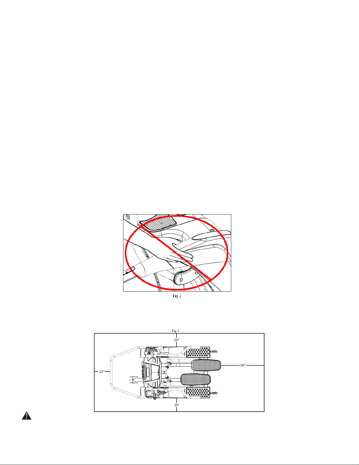
• Avoid placing hands on the upper side rail covers while elliptical is in operation. (See Fig 2)
SPACE REQUIREMENTS:
TRUE’s recommendation is to leave a 39” safety zone at rear of elliptical. The sides of the unit should be at least 20” away from the
wall or obstructions. (See Fig 1)
WARNING: The elliptical trainer is not equipped with a free wheel, therefore the moving parts are
unable to stop immediately.
Truefitness.com / 800.426.6570 / 636.272.7100 3
Page 8
CHAPTER 1: SAFETY INSTRUCTIONS
ELLIPTICAL ENTRY AND EXIT SAFETY:
Elliptical Entry:
• Step up onto the rear step.
• Step up onto the side platforms.
• Grip the heartrate handlebars for stability while
stepping onto the lowest pedal.
• Place opposite foot onto the other pedal.
Elliptical Exit:
• Stop pedaling by slowing leg motion and applying
slight resistance to the upper exercise arms.
• While gripping the heartrate handlebars for
stability, step from the highest pedal onto the side
platform.
• Place the opposite foot on the other side platform.
• Step down to the rear step.
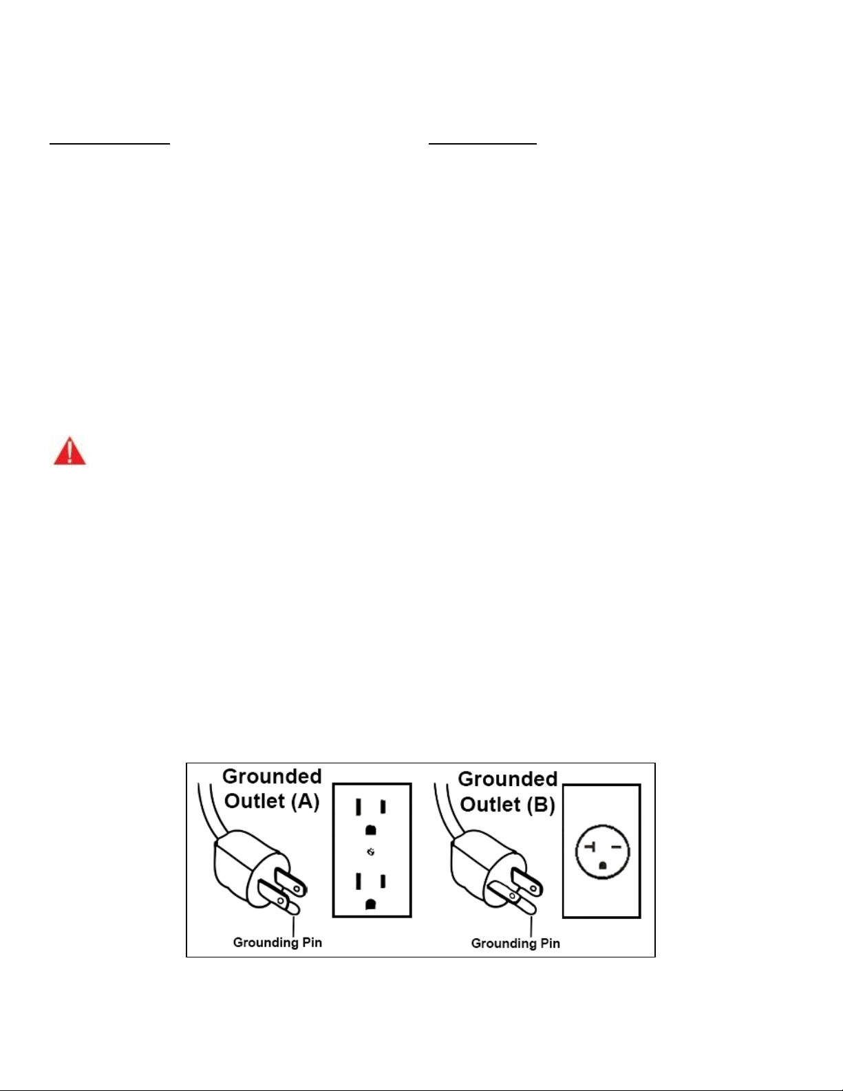
GROUNDING INSTRUCTIONS:
This product must be grounded, if it should malfunction or breakdown, grounding provides
current to reduce the risk of electric shock. This product is equipped with a cord having an equipment-grounding conductor and
a grounding plug. The plug must be plugged into an appropriate outlet that is properly installed and grounded in accordance with
all local codes and ordinances.
DANGER
• Improper connection of the equipment-grounding conductor can result in a risk of electric shock.
• Check with a qualified electrician or serviceman if you are in doubt as to whether the product is properly
grounded. Do not modify the plug provided with the product. If it will not fit the outlet, have a proper outlet
installed by a qualified electrician.
• Do not remove the motor cover or you may risk injury due to electric shock.
• The 120-V model is for use on a nominal 120-V circuit and has a grounding plug that looks like the plug
illustrated in figure A. Make sure the product is connected to an outlet having the same configuration as the plug.
No adaptor should be used with this product.
• The 230-V model is for use on a circuit having a nominal rating more than 120-V and is factory-equipped with a
specific electric cord and has a grounding plug that looks like the plug illustrated in figure B. Make sure that the
product is connected to an outlet having the same configuration as the plug in Figure B. No adapter should be
used with this product. If the product must be reconnected for use on a different type of electric circuit, the
reconnection should be made by qualified service personnel
:
a path of least resistance for electric
Truefitness.com / 800.426.6570 / 636.272.7100 4
Page 9

CHAPTER 1: SAFETY INSTRUCTIONS
Truefitness.com / 800.426.6570 / 636.272.7100 5
Page 10
CHAPTER 1: SAFETY INSTRUCTIONS
WARNING DECALS:
WARNING: Replace warning labels that may be worn, damaged or missing.
*To replace any worn or missing warning decals contact TRUE FITNESS by one of the following: www.truefitness.com or contact
customer service at 800-883-8783.
COMPLIANCES:
This equipment complies with all applicable codes and regulations. For a complete list of compliances, please visit
www.truefitness.com.
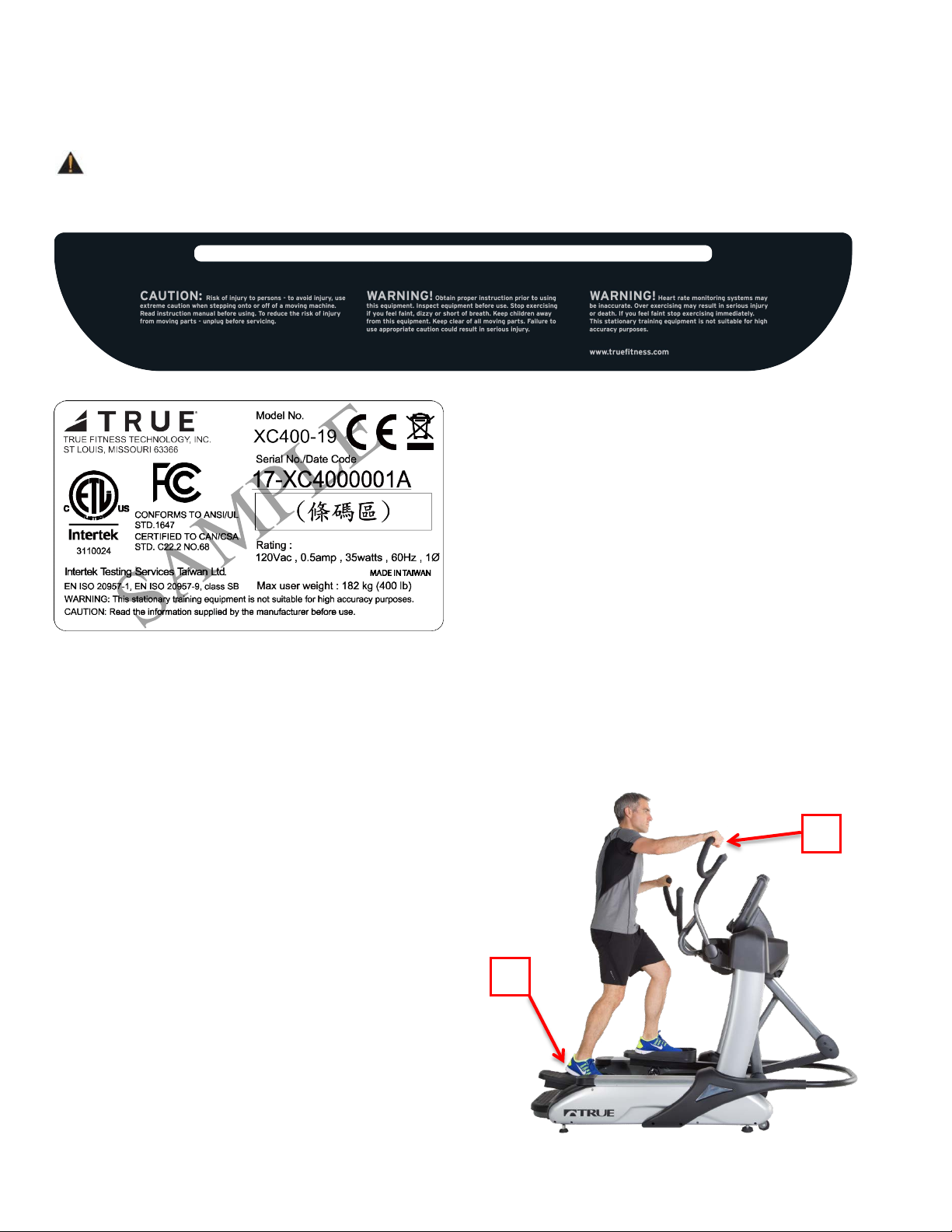
PROPER TRAINING POSITION:
• Users should keep both feet on the pedals (A)
during the workout.
• During a workout the user’s hand should grasp the
upper exercise arms (B).
• Users should remain standing throughout their
workout.
A
B
Truefitness.com / 800.426.6570 / 636.272.7100 6
Page 11

CHAPTER 2: ASSEMBLY INSTRUCTIONS
• Read and understand all instructions and warnings prior to use.
Keep the top side of the moving surface clean and dry.
Hardware:
IMPORTANT SAFETY INSTRUCTIONS
• Obtain a medical exam before beginning any exercise program. If at any time during exercise you
feel faint, dizzy, or experience pain, stop and consult your physician.
• Obtain proper instruction prior to use.
• Inspect the elliptical for incorrect, worn, or loose components and do not use until corrected,
replaced, or tightened prior to use.
• Do not wear loose or dangling clothing while using elliptical.
• Care should be used when mounting or dismounting elliptical.
• Disconnect all power (if applicable) before servicing elliptical.
• Do not exceed maximum user weight of 400 lbs.
• Keep children and animals away.
• Do not operate an electrically powered elliptical in damp or wet locations.
• All exercise equipment is potentially hazardous. If attention is not paid to the conditions of
equipment usage, death, or serious injury could occur.
•
*Should you need technical assistance in assembly of your TRUE Fitness product, contact TRUE Fitness Technical Support
at 1-800-883-8783.
PRE-ASSEMBLY CHECK LIST:
Tools Required:
10mm hex key (Included)
6mm hex key (Included)
#2 Phillips Screwdriver
Hardware is packaged in numbered
plastic bags that correspond to the
step with which they are used. Not
all steps require hardware.
Truefitness.com / 800.426.6570 / 636.272.7100 7
Page 12

CHAPTER 2: ASSEMBLY INSTRUCTIONS
Exercise Arms
Step 4
Side Arms
Step 3
Console
Step 6
Draw Bars
Step 2
Neck Shroud
Pedestal
Step 1
Front Guard &
Step 7
Leveling Feet
Step 8
Pedal Tubes
Step 5
ELLIPTICAL ASSEMBLY STEPS:
CAUTION:
• It is recommended that two people unpack and assemble elliptical.
• Remove bands from packaging and pull top from pallet.
• Remove all parts from packaging. Leave machine on pallet.
• For each step use hardware in the corresponding bag.
Sub-Assembly Identification:
Use the image below as a reference for where the provided sub-assemblies will be located in the complete elliptical
assembly:
Step 6
Boot Covers
Truefitness.com / 800.426.6570 / 636.272.7100 8
Page 13

CHAPTER 2: ASSEMBLY INSTRUCTIONS
Figure 2
Attach Handles
off the pallet
Remove handles from front of
into final placement
Figure 1
ELLIPTICAL ASSEMBLY STEPS (continued):
Pre-Assembly STEP 1: Install Transport Handle Bars:
a) Important: With machine still on pallet, attach handle bars to the front and rear of machine. Handle Bars will
provide assistance in moving machine. Figures 1 & 2
b) Carefully remove Elliptical from pallet.
c) Important: After final machine placement has been completed, remove transport handle bars from machine and
store handle bars with owner’s manual.
Base after machine is moved
to Base and use
both Front and
Rear Handles to
move Elliptical
Pre-Assembly STEP 2: Measure Doorways:
a) Measure all doorways, hallways and stairwells to make sure that the fully assembled elliptical (33 inches wide) can
fit through them.
b) If the fully assembled unit will not clear the doors and walls, move all parts to the final location and assemble
machine in that location. When moving the machine, keep the left side Styrofoam attached to the Base to help
avoid damaging the plastic covers. Set the base on the Styrofoam or the feet only. Figure 4
Please Note When Moving The Elliptical:
Elliptical base can be set
on its LEFT side, but
ONLY with the attached
Styrofoam underneath
Figure 4
Truefitness.com / 800.426.6570 / 636.272.7100 9
it.
Page 14

CHAPTER 2: ASSEMBLY INSTRUCTIONS
ELLIPTICAL ASSEMBLY STEPS (continued):
STEP 1: Assemble Pedestal to Base:
a)
b) Use 2 people to slide the Pedestal
c)
M8x12mm
Bolts
M12x12mm
Bolt
Insert these bolts
other bolts
Remove Front Handles before
assembling Pedestal.
straight down onto the Base and be
careful to not pinch the wires on the
right side of the base.
Use 2 M12x12mm bolts and 8
M8x12mm bolts to attach Pedestal to
Base and then connect the cables
coming from the right pedestal to
the corresponding wires in the base.
Hardware Required (Bag 1):
8 M8x12m
m Bolts
first to help align
2 M12X12mm
Bolts
Truefitness.com / 800.426.6570 / 636.272.7100 10
Page 15

CHAPTER 2: ASSEMBLY INSTRUCTIONS
ELLIPTICAL ASSEMBLY STEPS (continued):
STEP 2: Attach Drawbars:
a)
2 M10 Bolts
2 Flat Washers
2 Lock Washer
b) Attach the bottom of each draw
c) Use the remaining hardware in
2 M5x10 Screws
3 M3x12 Screws
Slide the top of the draw bars onto
the exposed shaft and use the bolts,
lock washers and flat washers from
bag 2 to secure the push rod.
Hardware Required (Bag 2):
bar to rear crank with M8 x 12mm
bolts.
Hardware Required (Bag 2):
8 M8x
12mm Bolts
bag 2 to attach the drawbar covers.
Hardware Required (Bag 2):
6 M3x
12 Screws
8 M5x12mm Screws
Truefitness.com / 800.426.6570 / 636.272.7100 11
Page 16

CHAPTER 2: ASSEMBLY INSTRUCTIONS
ELLIPTICAL ASSEMBLY STEPS (continued):
STEP 3: Attach Side Arms:
a
c
STEP 4: Upper Exercise Arms:
Connect Wires
and the Side Arms
4 Bolts per Arm
) Connect Side Arm Heart Rate
Cable
b) CAREFULLY Slide Side Arm into
Pedestal and tuck the Heart Rate
Cable into the tube. Make sure to not
pinch the Heart Rate Cable wires.
) Use 4 M8x12mm bolts to tighten
the Side Arms into the underside of
the Pedestal.
Hardware Required (Bag 3):
between the Pedestal
4 M8x12bolts
a) Install each upper arm with 4
M8x1.25x16mm bolts using a 6 mm
hex key.
Note: Upper Arms are labeled "L"
for Left and "R" for Right.
Hardware Required (Bag 4):
8 Tapered M8x16mm Bolts
Truefitness.com / 800.426.6570 / 636.272.7100 12
Page 17

CHAPTER 2: ASSEMBLY INSTRUCTIONS
ELLIPTICAL ASSEMBLY STEPS (continued):
STEP 4: Upper Exercise Arms (continued):
b)
STEP 5: Attach Pedal Tubes:
a
2 M10 Nuts
b) Attach the Front Pedal Tub e
Attach the Exercise Arm Covers
using 4 M5x8mm screws for each
side.
Hardware Required (Bag 4):
8 M5x8mm Screws
) Use 2 M10x80mm bolts and 2
M10 Nuts to attach Pedal Tubes.
Make sure that pedal tubes ar
c
entered between the rollers of
C
rankshaft before tightening t
b
olts.
Hardware Required (Bag 5):
2 M10x80mm Bolts
Covers using 8 M5x12mm screws.
Hardware Required (Bag 5):
8 M5x12mm Screws
e
the
he
Truefitness.com / 800.426.6570 / 636.272.7100 13
Page 18

CHAPTER 2: ASSEMBLY INSTRUCTIONS
ELLIPTICAL ASSEMBLY STEPS (continued):
STEP 6: Console Assembly – Console Mast:
a
STEP 6: Console Assembly – Front Neck Panel:
b) Attach Front Neck Panel to the
STEP 6: Console Assembly – Console Mounting:
c) Attach Console to the Console
Route Cables Here
2 M8x12mm bolts
2 M8x20mm bolts
Ground
Screw
) Slide Console cables through
Console Mast and attach Mast using
8x12mm bolts and 2 M8x20mm
2 M
bolts.
CAUTION: Do not pinch wires!
Hardware Required (Bag 6):
2 M8x12mm Bolts
2 M8x20mm Bolts
Front Mast using 2 Phillips head
bolts.
Hardware Required (Bag 6):
2 M5x12mm Bolts
Mast with 4 M5x10mm bolts.
d) Attach the console ground wire to
the Console Mast
Hardware Required:
*I
ncluded with Console
Truefitness.com / 800.426.6570 / 636.272.7100 14
Page 19

CHAPTER 2: ASSEMBLY INSTRUCTIONS
e)
STEP 7: Front Guard & Boot Covers:
a)
d
2 M8x12mm bolts
M8x20mm bolts
ELLIPTICAL ASSEMBLY STEPS (continued):
STEP 6: Console Assembly (continued) – Rear Console Cover:
Attach the Rear Console Cover
using 2 M5x12mm screws.
Hardware Required (Bag 6):
2 M5x12mm Screws
Slide front guard between the
front covers and the frame and
secure it to the frame using 4 M8x20
bolts.
Hardware Required (Bag 7):
2 M8x20mm Bolts
) Snap the 2 Front Boot Covers
into place on the base and use 4
M4 screws to tighten down the
Boot Cover.
Hardware Required (Bag 7):
4 M4 Screws
Truefitness.com / 800.426.6570 / 636.272.7100 15
Page 20

CHAPTER 2: ASSEMBLY INSTRUCTIONS
ELLIPTICAL ASSEMBLY STEPS (continued):
STEP 8: Floor Levelers:
a)
STEP 9: Remove Transport Handles:
a)
STEP 10: Remove Protective Film from Decals:
a) Once Elliptical is moved into its
If necessary, adjust four levelers on
bottom of machine to accommodate
uneven flooring.
Once Elliptical is moved into its
final location, remove the two
Handle Bars on the back of the
machine and store with owner’s
manual for future use.
final location, remove the protective
film from the decals and from the
“True” on the lower shroud.
Truefitness.com / 800.426.6570 / 636.272.7100 16
Page 21

CHAPTER 2: ASSEMBLY INSTRUCTIONS
ELLIPTICAL ASSEMBLY STEPS (continued):
*This step is REQUIRED for units that are paired with a touchscreen or 15” TFT console.
a)
c) Disconnect the lower board
e) Connect the Power Supply input &
Input
Connection
Output
Connection
STEP 11: Auxiliary Power Supply:
Remove the rear access plastics on
the user’s right sided of the elliptical.
b) Locate and cut the wire tie that
holds the power cable.
latching power cable.
d) Connect the power cable to the
power supply latching connector.
output connections as shown.
Disconnect Reconnect
Truefitness.com / 800.426.6570 / 636.272.7100 17
Page 22

CHAPTER 2: ASSEMBLY INSTRUCTIONS
ELLIPTICAL ASSEMBLY STEPS (continued):
*This step is REQUIRED for units that are paired with a touchscreen or 15” TFT console.
f)
h) Re-install access plastics.
STEP 11: Auxiliary Power Supply (continued):
Mount Power Supply on bracket
and attach with wire ties.
g) Tuck excess wires inside shroud
opening
Wire ties
Tuck excess wires into
shroud opening
Truefitness.com / 800.426.6570 / 636.272.7100
18
Page 23

CHAPTER 2: ASSEMBLY INSTRUCTIONS
WIRING DIAGRAMS:
Truefitness.com / 800.426.6570 / 636.272.7100 19
Page 24

CHAPTER 2: ASSEMBLY INSTRUCTIONS
WIRING DIAGRAMS (continued):
Truefitness.com / 800.426.6570 / 636.272.7100 20
Page 25

REV.
WEIGHT (KG)
XC400
DESCRIPTION QTY.
Rexon Part #
ITEM NO. PART NUMBER
HANDLEBAR 2
SIZE
A
REMOVABLE HANDLE 2
M12X12 SOCKET HEAD SCREW 2
M8X12 BOLT, HES SOC. HD. CAP 2602266 8
M8X12 TAPERED SOCKET HEAD SCREW 8
CONSOLE PAD, TRUE BLUE - XCS400 1
XC400
DWG. TRUE PART #:
DATE
M4X16 TRUSS HD TAPPING SCREW ( FOR SHROUD ) 4
O'FALLON, MO. 63366
26023B5E
2602261H
10C72JC9
1 7XC0020 XC400 BASE ASSEMBLY 1
2 7XES0033
3 7XC0021 PEDESTAL ASSY - XCS400 1
4 7SX0036
5 26023B5E
10J33B6N
6 7XCS0031R LINKAGE ASSY (R) - XCS400 1
7 7XCS0031L LINKAGE ASSY (L) - XCS400 1
8 7XPS0011A
10K43Q0X
9 7XCS0025B UPPER EXERCISE ARM: XCS400/R; XCS900/L 1
10 7XCS0025A UPPER EXERCISE ARM: XCS400/L; XCS900/R 1
11 10K43Q0X
12 7XCS0032 PEDAL TUBE ASSY - XCS400 2
13 7XCS0038 REAR CONSOLE COVER ASSY - XCS400 1
266138GU
14 7XCS0035L LEFT PEDESTAL BASE COVER 1
15 7XCS0035R RIGHT PEDESTAL BASE COVER 1
16 7XPS0078
17 7XCS0099 ROCKER ARM COVER SET 2
18 7XCS0039R SHAFT COVER SET (R) - XCS400 1
19 7XCS0039L SHAFT COVER SET (L) - XCS400 1
20 7XC0027 RIGHT LINKAGE PIVOT ASSEMBLY 1
21 7XC0028 LEFT LINKAGE PIVOT ASSEMBLY 1
10J339QF
22 7XCS0020 FOOT SKATE ASSEMBLY 2
23 7XCS0019 FOOT PAD WITH VELCRO 2
24 7XCS0006
25 7XCS0005 CONSOLE MAST ASSY - XCS400 1
26 7XCS0021 FRONT EXTENDED TUBE ASSY - XCS400 1
TITLE
NOTES:
MATERIAL:
BREAK ALL SHARP
DRAWN BY
IN MILLIMETERS
DIMENSIONS ARE
CORNERS & EDGES
TOLERANCES UNLESS NOTED:
UNLESS OTHERWISE SPECIFIED
13
25
FITNESS TECHNOLOGY, INC.
.X ±.787mm
.XX ±.381mm
.XXX ±.127mm
HOLES ±.127mm
ANGULAR ±1°
DECIMALS:
DO NOT SCALE DRAWING
-
APPRVL
-
-
DATE BY
26
14
21
4
16
16
17
17
4
5
4
3 19
5
4
DESCRIPTION
ORIGINAL RELEASE
XC400
4
24
11
10
9
8
4
4
4
20
7
1
16
-
A
REV. MCF#
16
2
18
6
15
2
8
11
23
22
23
22
12
12
CONFIDENTIAL INFORMATION
ARE FOR REFERENCE ONLY
NOTE: ALL WEIGHTS AND DIMENSIONS
DETRIMENTAL TO THE INTERESTS OF TRUE FITNESS TECHNOLOGY, INC.
CONFIDENTIAL USE. SUBJECT TO RETURN ON REQUEST, AND WITH THE
MUTUAL UNDERSTANDING THAT IT WILL NOT BE USED IN ANY MANNER
OF TRUE FITNESS TECHNOLOGY, INC. O'FALLON, MO. IT IS LOANED FOR
21
Page 26

1
1
2
1
1
1
2
2
1
2
W/WASHER
CAP 2602266
COVER - XCS400
FRONT LOWER CONSOLE
M5X12 PAN HEAD SCREW
M8X12 BOLT, HES SOC. HD.
23.2 7XC00 23 10J63C0M
23.3 2641B BDA39 26412DUB
23.4 7SX00 36 2602261H
23.5 26022 ZXH 26022ZXH M8X20 SOCKET HEAD BOLT 2
ITEM NO. PART NUMBER Rexon Par t # DESCRIPTION QTY.
1
WELDMENT
LEFT UPPER EXERCISE ARM
10.1 7XC0051 10J63CGS
ITEM NO. PART NUMBER Rexon Par t # DESCRIPTION QTY.
1
BRACKET
SALUTRON BOARD
23.6 2668B ZDA22 2668BZDA22 M5X6 PA N HEAD SCREW 1
1
1
KNOB, HANDLEBAR
CHROME 10E12NNN
COLLAR, HANDLEBAR
10.2 7PX0130 10E12NNN
10.3 10J63CJY 10E12NQQ UPPER EXERCISE ARM GRIP 1
10.1.1 10J63CTN 10J63CTN-1 1
10.4 7PX0131 10E12NNP
10.1.2 10J339N3 1
3
STANDOFF SCREW
SALUTRON BOARD
COVER
ASSY - XCS400
LEFT PEDESTAL BASE
FRONT EXTENDED TUBE
25 7XCS0035L
24 7XCS0021
24.2 26022 ZXH 26022ZXH M8X20 SOCKET HEAD BOLT 4
24.1 7XC00 24 10J63C01 CHIN BAR 1
8
HEAD SCREW
CHROME 10E12NNP
M8X12 TAPERED SOCKET
11 10K43Q0X 10K43Q0X
12 7XCS0032 PEDAL TUBE ASSY - XCS400 2
10.5 7XC0050 26062SJ Z SET SCREW 4
1
3
SHROUD
HEADED SCREW
INSERT, REGULAR CAP
UPPER PEDESTAL PLASTIC
M5X16 PHILLIPS ROUNDED
COVER
- XCS400
PEDESTAL BASE COVER (L)
25.1 7XC00 26 10J63C0Q
12.1 7XC0053 10J33E0B PEDAL TUBE WELDMENT 1
12.2 7XC0054 2001 ZZ6203 BEARING 2
8
TYPE, 5/16" PLASTIC BOSS
- XCS400
RIGHT PEDESTAL BASE
INSERT, REGULAR CAP
12.3 7XC0055 10C32GS1 BEARING ROD 1
INSERT, REGULAR CAP
TYPE, 5/16" PLASTIC BOSS
25.2 7XC00 34 271437W1
12.4 7SX0105 2570BBN117 C RING 2570BBN117 2
TYPE, 5/16" PLASTIC BOSS
PEDESTAL BASE COVER (R)
26 7XCS0035R
26.1 7XC00 25 10J63C0R
26.2 7XC00 34 271437W1
1
1
1
1
1
2
4
1
1
4
1
1
3
1
1
3
1
1
1
3
2
1
1
1
3
2
4
(R)
SHROUD
SHROUD
260121BA
M10X80 BOLT, HEX HEAD
12.5 7SX0115 260121BA
12.6 7SX0116 270122RR NUT, HEX 270 122RR 1
12.7 7XC0056 10J339QE 1" VELCRO S QUARE 6
6
4
3
2634BFDA24
INSERT, REGULAR CAP
SCREW ( FOR SHROUD )
TYPE, 5/16" PLASTIC BOSS
M4X16 TRUSS HD TAPPING
SCREW, CR.-RE. TRUSS HD.
- XCS400
ASSY - XCS400
CONSOLE COVER
REAR CONSOLE MAST
REAR CONSOLE COVER
13 7XCS0038
1
BOTTOM PEDESTAL COVER
UPPER CONSOLE COVER
M5X12 SCREW, CR RE PAN
COVER UPPER INSERT ASSY
13.1 7XC0057 10J63C0L
13.2 7XCS0004
13.2.1 7XC0087 10J63CUA
8
FRONT
M8X12 BOLT, HES SOC. HD.
13.2.2 2660MZCE10 2660MZCE10 M4X8 PAN HEAD SCREW 2
2
1
1
SCREW
XCS400
CAP 2602266
WELDMENT
LINKAGE ASSY (R) -
RIGHT LINKAGE ARM
M12X12 SOCKET HEAD
SHROUD
HEAD 26682RYH
SCREW ( FOR SHROUD )
M4X16 TRUSS HD TAPPING
LEFT ROCKER ARM COVER
14 7XPS0078 266138GU
15 7XCS0099 ROCKER ARM COVER SET 2
13.3 7CX0079 26682RYH
15.1 7XC0058 10J63C0N
2
1
1
2001ZZ6005
thick- 2.2 mm
BEARING, BALL 6005ZZ
OD- 35mm, thick: 2mm
SPLIT LOCK WASHER M10,
FLAT WASHER ID- 10.2mm,
XCS400
2634BFDA24
COVER SHROUD
RIGHT ROCKER ARM
SHAFT COVER SET (R) -
RIGHT SHAFT COVER SET
SCREW, CR.-RE. TRUSS HD.
15.2 7XC0059 10J63C0P
15.3 7SX0004 2634BFDA24
1
4
SCREW
26012DVG
M8X12 SOCKET HEAD
M10X20 BOLT, HEX HEAD
M5X8 SCREW, CR RE PAN
16 7XCS0039R
16.1 7XC0060 10J339Q0
16.2 7XC0061 10J 63CU8 LEFT SHAFT COVER SET (R) 1
16.3 7CX0063 26682NAK
1
2
4
SCREW
WELDMENT
2001ZZ6005
LEFT LINKAGE ARM
M8X12 SOCKET HEAD
BEARING, BALL 6005ZZ
(L)
HEAD
SHAFT COVER SET (L) -
17 7XCS0039L
1
OD- 35mm, thick: 2mm
FLAT WASHER ID- 10.2mm,
HEAD
XCS400
17.1 7XC0062 10J339Q1 LEFT SHAFT COVER SET (L) 1
1
thick- 2.2 mm
SPLIT LOCK WASHER M10,
ASSEMBLY
RIGHT LINKAGE PIVOT
RIGHT SHAFT COVER SET
M5X8 SCREW, CR RE PAN
18 7XC0027
17.2 7XC0063 10J 63CU7
17.3 7CX0063 26682NAK
1
26012DVG
M10X20 BOLT, HEX HEAD
HEAD SCREW
PIVOT COVER
PIVOT COVER
RIGHT INNER LINKAGE
RIGHT OUTER LINKAGE
M3X12 PHILLIPS ROUNDED
18.1 7CE90175 10E12N7B
18.2 7CE90174 10 E12N7A
18.3 26342RYG 26342RYG
1
1
SENSOR
PLASTIC FRAME
BOTTOM HAND PULSE
BOTTOM PULSE SENSOR
COVER
COVER
ASSEMBLY
2634BFDA24
LEFT LINKAGE PIVOT
SCREW, CR.-RE. TRUSS HD.
LEFT OUTER LINKAGE PIVOT
19 7XC0028
18.4 7SX0004 2634BFDA24
19.1 7CE90172 10 E12NKV
1
1
1
PULSE SENSOR
PLASTIC FRAME
TOP PULSE SENSOR
METAL BOTTOM HAND
METAL TOP HAND PULSE
2634BFDA24
HEAD SCREW
SCREW, CR.-RE. TRUSS HD.
M3X12 PHILLIPS ROUNDED
LEFT INNER LINKAGE PIVOT
19.2 7CE90173 10E12NKU
19.3 26342RYG 26342RYG
2
SENSOR
CAP 2602266
M8X12 BOLT, HES SOC. HD.
M5X16 PHILLIPS ROUNDED
20 7XCS0020 FO OT SKATE ASSEMBLY 2
19.4 7SX0004 2634BFDA24
20.1 7XC0090 10J63DZ1 FOOT SKATE - XCS400 1
20.2 26343AG9 26 343AG9
1
1
ARM WELDMENT
XCS400/R; XCS900/L
UPPER EXERCISE ARM:
RIGHT UPPER EXERCISE
1
1
XCS400
HEAD SCREW
- XCS400
CONSOLE MAST ASSY -
CONSOLE PAD, TRUE BLUE
21 7XCS0019 FOOT PAD WITH VELCRO 2
22 7XCS0006 10J339QF
23 7XCS0005
21.1 7XC0089 10J63DZ3 FOOT PAD - XCS400 1
21.2 7XC0056 10J339QE 1" VELCRO S QUARE 6
23.1 7XC0022 10J63C0A CONSOLE MAST 1
1
1
1
KNOB, HANDLEBAR
CHROME 10E12NNP
CHROME 10E12NNN
XCS400/L; XCS900/R
COLLAR, HANDLEBAR
UPPER EXERCISE ARM:
4 7SX00 36 2602261H
5 26023 B5E 26023B 5E
6 7XCS00 31R
6.1 7X C0043 10E12N2W
6.2 7SX 0126 2001Z Z6005
6.3 7X P0154 10C32DM4
3.11 7XC00 40 10K73U52
3.12 7XC00 41 10F13U58
3.13 70061 422 10F13U34 SALUTRON BOARD 1
3.14 26693 R62 26693R62 M2X4 PAN HEAD SCREW 3
3.11.1 -
ITEM NO. PART NUMBER Rexon Par t # DESCRIPTION QTY.
2
WASHER
HEAD SCREW WITH
M5X16 PHILLIPS ROUNDED
1.23 2620B ZDB18 2620BZDB18
ITEM NO. PART NUMBER Rexon Par t # DESCRIPTION QTY.
3.15 7XPS0 031 101J33B7 6 UPPER COVER ASSEMBLY 1
3.15.1 7XC0081 10J 339NY
2
1
1
XCS400
XCS400
2634BFDA24
POWER INLET ASSY -
INNER FRONT EXCESS (R) -
SCREW, CR.-RE. TRUSS HD.
1.24 7SX00 04 2634BFDA24
1.25 7XCS00 27R 10 J63C1L
1.26 7XCS00 37
1.26.1 7XC0078 10J63C0 K POWER INLET SHROUD 1
1.26.2 10F12V86 COAXIAL CONNECTOR 1
1
XCS400
GENERATOR BRAKE ASSY -
3.16 7XC00 42 2707FBN108 PEDESTAL SCREW CLIP 3
3.17 7XPS0 043 10J339P4 BOTTOM P EDESTAL COVER 1
3.18 7XC00 34 271437W1
3.19 7XPS0 078 266138GU
3.20 7SX00 04 2634BFDA24
3.15.2 7XC0082 10F12SV8 PLUG, INNER SHROUD 3
3.15.3 2653MZDE18 2653M ZDE18
3.15.4 7XC0034 271437W1
1
1
1
XCS400
NO DECALS
CONNECTOR
POWER SWITCH AND
LAN CONNECTOR 3018 -
COVER, LEFT OUTER WITH
1.27 7XC00 35 10J339QA
1.26.3 7XCS0028 10E13018
1
M8X40 SOCKET HEAD
1.28 7XC00 36 11302LFU COVER SUPPORT POST 6
1.26.4 10J33BCZ 10J33BCZ
1.26.5 26682D1X 26682D1X M5X6 PAN HEAD SCREW 2
3
4
BOLT
BOLT
SCREW
M5X16 SEMS HEX HEAD
M6X14 SEMS HEX HEAD
3.21 7XPS0 044 10J339P5
1
XCS400
INNER FRONT EXCESS (L) -
1.29 2701F ZD113 2701FZD113 M8X6.5 HEX NUT 6
1.30 7XPS0 049 10J339QB COVER, INNER FR ONT LEFT 1
1.31 7XCS00 27L 10J63C1K
1.32 7XPS0 052 10J339QC COVER, INNER REAR LEFT 1
1.33 00591 500 LOWER CONT ROL BOARD 1
1.34 7XPS0 021L LEFT SIDE STEP 1
1.35 7XPS0 021R RIGHT SIDE STEP 1
1.34.1 7XC0031 10J339QD LEF T SIDE STEP 1
1.34.2 26343E28 26343E28 M 5X8 PAN HEAD SCREW 4
1.35.1 7XC0032 10J339 Q8 RIGHT SIDE STEP 1
1.35.2 26343E28 26343E28 M 5X8 PAN HEAD SCREW 4
2
12
2001ZZ6005
BEARING, BALL 6005ZZ
2
CLAMP
ROLLER HOUSING
PEDAL TUBE BEARING
BOTTOM CRANK SHAFT
6.4 25 02AZC410 2502AZC410
1
XCS400
DISC COVER SHROUD -
SCREW, CR.-RE. TRUSS HD.
1.36 10J 33AGG 10J33 AGG SILVER DECAL 2
1.37 7XCS00 13 DISC CO VER ASSEMBLY 2
1.37.1 7XC0030 10J63C5 5
4
4
BOLT
M12X65 PARTIALLY
M5X16 SEMS HEX HEAD
THREADED SOCKET HEAD
7 7XCS00 31L LINKAGE ASSY (L) - XCS400 1
6.5 7PX 0153 26012DVG
6.6 26 023C89 26023C89
7.1 7X C0044 10E12N2V
7.2 7SX 0126 2001Z Z6005
7.3 26 023C89 26023C89
2
1
1
SCS400
ASSEMBLY
2634BFDA24
BELT TENSION ROD
BELT TENSIONER ROD -
2 7XES003 3 10C72JC9 REMOVA BLE HANDLE 2
3 7XC00 21 PEDESTAL ASSY - XCS400 1
1.38 7XCS00 02
1.37.2 7SX0004 2634BFDA24
1.38.1 7XC0092 10J63C0D
1.38.2 2705FZD108 2705FZD1 08 M8 LOCK NUT 1
4
2
BOLT
SCREW
KEY,PARALLEL XPSX
M12X30 SOCKET HEAD
3.1 7X C0037 10J63C05 PEDESTAL WELDMENT 1
1.39 7XCS00 14 25723CGL DRIVE BELT 1
1.38.3 2501MFDN34 2501MFDN34 M8- 1 8MM FLAT WASHER 1
2
2571MNC332
M10X20 HEX DRIVE
ROUNDED HEAD BOLT
8 7XPS00 11A 10J33B6N HANDLEBAR 2
7.4 7X P0154 10C32DM4
7.5 25 02AZC410 2502AZC410
7.6 7PX 0153 26012DVG
8.1 7X C0045 10J339PU HANDLEBAR WELDMENT 1
8.2 7X C0046 10J339P1
8.1.1 10J 339PV 1
8.1.2 10J 339PU-1 1
1
2
1
XCS400
HANDRAIL TUBE ASSY (R) -
3.2 7X CS0026R
3.2.1 7XT 0005 10C72N1P SHAFT , LINKAGE 10C72N1P 1
3.2.2 7SX0 095 2570BBN125 C R ING 2570BBN125 1
2
ASSEMBLY
TRANSPORT WHEEL
WELDMENT
2001ZZ6005
BEARING, BALL 6005ZZ
RIGHT HANDRAIL TUBE
3.2.3 7SX0 126 2001ZZ6005
3.2.4 7XC00 66 10C32DUW 8 MM SPACER 1
3.2.5 7XC00 67 26062TXR SET SCREW 2
3.2.6 7XC00 79 10J63BZ R
1
HEADED BOLT
M8X45 PHILLIPS ROUNDED
8.3 7X C0047 10J339NZ TOP HAND PULSE SENSO R 1
8.2.1 7XC00 83 10J 339P1-1
8.2.2 7XC00 84 10J339P2
8.3.1 7XC00 85 10J339 NZ-1
2
2
1
SCREW
XCS400
CAP 2602266
M8X40 SOCKET HEAD
M8X12 BOLT, HES SOC. HD.
3.2.7 26022 NA6 26022N A6
3.2.8 7SX0 036 2602261H
BEARING, BALL 6005ZZ
HANDRAIL TUBE ASSY (L) -
3.3 7X CS0026L
3.3.1 7XT 0005 10C72N1P SHAFT , LINKAGE 10C72N1P 1
3.3.2 7SX0 095 2570BBN125 C R ING 2570BBN125 1
8
1
HEAD SCREW
POWER SUPPLY, FUYANG
M5X10 PHILLIPS ROUNDED
12V 6A NO POWER CORD
9 7XCS00 25B
8.4 26 373DJ1 26373DJ1 M3X 30 PAN HEAD SCREW 2
8.5 7SX 0036 2602261H
9.1 7X C0048 10J63 CGT
8.3.2 7XC00 86 10J339P0
2
1
WELDMENT
2001ZZ6005
LEFT HANDRAIL TUBE
M8X40 SOCKET HEAD
3.3.3 7SX0 126 2001ZZ6005
3.3.4 7XC00 66 10C32DUW 8 MM SPACER 1
3.3.5 7XC00 67 26062TXR SET SCREW 2
3.3.6 7XC00 80 10J 63BZQ
1
1
NO DECALS
(IATA SP A67)
M4X16 TRUSS HD TAPPING
BATTERY, YUSA NP 2.3-12F R
COVER, RIGHT OUTER WITH
9.2 7PX 0130 10E12NNN
9.1.1 10J 63CTP 10J63CTP-1 1
9.1.2 10J 33Q5C 1
2
2
4
SCREW
CAP 2602266
NUCLEUS BOARD
STANDOFF SCREW
M8X12 BOLT, HES SOC. HD.
3.4 7X C0038 10J63U67 UPPER BOARD BRACKET 1
3.5 7X C0039 10F13U59
3.3.7 26022 NA6 26022N A6
3.3.8 7SX0 036 2602261H
6
26
M5XP0.8X12
PAN HEAD SCREW
SCREW ( FOR SHROUD )
INSERT, REGULAR CAP
10 7XCS0025A
9.3 10 J63CJY 10E12NQQ UPPER EXERCISE ARM GRIP 1
9.4 7X C0050 2606 2SJZ SET SCREW 4
9.5 7PX 0131 10E12NNP
2
2
M6X10 HEX DRIVE
M5 - 11mm EXTERNAL
TOOTH LOCK WASHER
ROUNDED HEAD SCREW
3.6 70 0612700 10F13U33 NUCLEUS BOARD 1
3.7 26 68BZDA06 2668BZDA06 M4X5 PAN HEAD SCREW 4
3.8 26 082HDZ 26082HDZ
3.9 25 04MZC006 2504MZC006
3.10 2668B ZDA22 2668BZDA22 M5X6 PA N HEAD SCREW 4
6
2
1
RIGHT
M5 - 11mm EXTERNAL
COVER, INNER FRONT
TOOTH LOCK WASHER
TYPE, 5/16" PLASTIC BOSS
22
1 7X C0020 XC400 BASE ASSEMBLY 1
1.1 7XC0029 XC400 BA SE WELDMENT 1
1.2 7XCS0023
1.2.1 7 XC0064 10J 63C3R GENERATOR BRAKE 1
1.2.2 7 XCS0105 IDLER BRACKET ASSY 1
1.2.2.1 7XC0088 10 J63BZV IDLER WELDMENT 1
1.2.2.2 7PX0011 2001ZZ6204 Bearing 2
1.2.2.3 7SX0097 2570BBN120 Snap Ring 1
1.2.2.4 250136GL 250136GL M8 - 28MM FLAT WASH ER 1
ITEM NO. PART NUMBER Rexon Par t # DESCRIPTION QTY.
1.2.2.5 26022NA6 26022NA6
1.3 7XCS0008 CRANK SHAFT - XC S400 1
1.2.3 2 6173FZ6 26173FZ6
1.3.1 7 XC0065 10E12SY5 CRANK SHAFT BAR 1
1.3.2 7 XC0066 10C32DUW 8 MM SPACER 2
1.3.3 7 XC0067 26062TXR SET SCREW 4
1.3.4 7 SX0126 2001ZZ6005
1.3.5 7 XC0068 10C32CU8 BEARING HOUSING 2
1.3.6 7 CX0085 10F12R1B BEARING SPACER 2
1.3.7 7 XC0069 10C32CS3
1.3.8 7 XC0070 10J63C0J
1.3.9 7 XC0071 10J63C0H TOP CRANK SHAFT CL AMP 2
1.3.10 26173AZ8 26173AZ8
1.3.11 7XC0072 10E12SY8 CRANK SHAFT WELDMENT 2
1.3.12 26022T1G 26022T1G
1.3.13 270533N5 270533N5 M12X12 LOCK NUT 4
1.3.14 26023FXU 26023FXU
1.3.15 7XC0073 10C72SPB 7.5 MM SPACER 2
1.2.2.6 7CX0048 11 0821X8 Spacer 3
1.2.2.7 26173AZ8 2617 3AZ8
1.3.16 7PX0017 2571MNC332
1.4 7XCS0015 10J63C0C DRIVE WHEEL - XCS400 1
1.5 7XCS0018 10J63 C0E FLY WHEEL (R) - XCS400 1
1.6 7XPS0007
1.6.1 7 XC0075 11232 AX2 WHEEL - FLOOR R OLLER 1
1.3.17 7XC0074 10C72SD9 BEARING SPA CER 2
1.3.18 25012MPQ 25012MPQ M10 - 30MM FLAT WA SHER 2
1.3.19 7SX0124 260822QV
1.6.2 7 XC0076 10E32MR4 WHEEL SHAFT 1
1.7 7XPS0008 LEVELING FOOT ASSEMB LY 4
1.8 7XPS0058 10 J339NW LEFT FOOT B RACKET 1
1.9 7XPS0059 10J339NX RIGHT F OOT BRACKET 1
1.10 26342H7T 26342H7T
1.11 70595500
1.12 70588800
1.13 7XC0052 10C82HLD XC400 CHAR GING PORT 1
1.14 7XC0033 10J339Q4
1.15 7XPS0078 266138GU
1.16 7XCS0100 266833N0
1.17 7CX0122 10J33A2Y TRUE BLACK DECAL 2
1.18 7XPS0051 10J339Q6 COVER, INNER REAR RIGHT 1
1.19 7XC0034 271437W1
1.20 2504MZC006 2504MZC006
1.21 2668BZDA22 2668BZDA22 M5X6 PA N HEAD SCREW 2
1.6.3 2 6082MZB 26082MZB
1.6.4 2 705FZD108 2705FZD108 M8 LOCK NUT 1
1.6.5 2 501NZDN65 2501NZDN65 M8 - 19MM FLAT WASH ER 1
1.7.1 7 SX0042 10B826LH PAD, LEVELING 1
1.7.2 7 XC0077 10C22M0X LEVELING FOOT SPACER 1
1.22 7XPS0050 10J339Q5
Page 27

0
REV.
WEIGHT (KG)
7XC0020
SIZE
A
DWG. TRUE PART #:
DATE
XC400 BASE ASSEMBLY
NOTES:
MATERIAL:
8 7XPS0058 10J339NW LEFT FOOT BRACKET 1
9 7XPS0059 10J339NX RIGHT FOOT BRACKET 1
6 7XPS0007 TRANSPORT WHEEL ASSEMBLY 2
1 7XC0029 XC400 BASE WELDMENT 1
2 7XCS0023 GENERATOR BRAKE ASSY - XCS400 1
3 7XCS0008 CRANK SHAFT - XCS400 1
ITEM NO. PART NUMBER Rexon Part # DESCRIPTION QTY.
7 7XPS0008 LEVELING FOOT ASSEMBLY 4
4 7XCS0015 10J63C0C DRIVE WHEEL - XCS400 1
5 7XCS0018 10J63C0E FLY WHEEL (R) - X CS400 1
10 26342H7T 26342H7T M5X10 PHIL LIPS ROUNDED HEAD SCREW 8
14 7XC0033 10J339Q4 COVER, RIGHT OUTER WITH N O DECALS 1
15 7XPS0078 266138GU M4X16 TRUSS HD TAPPING SCREW ( FOR SHROUD ) 6
11 70595500 POWER SUPPLY, FUYANG 12V 6A NO POWER CORD 1
12 70588800 BATTERY, YUSA NP 2.3-12FR (IATA SP A 67) 1
16
16 7XCS0100 266833N 0 PAN HEAD SCREW M5XP0.8X12 26
13 7XC0052 10C82HLD XC400 CHARGING PORT 1
17 7CX0122 10J33A2Y TRUE BLACK DECAL 2
18 7XPS0051 10J339Q6 COVER, INNER R EAR RIGHT 1
22 7XPS0050 10J339Q5 COVER , INNER FRONT RIGHT 1
23 2620BZDB18 2620BZDB18 M5X16 PHILLIPS ROUNDED HEAD SC REW WITH WA SHER 2
24 7SX 0004 2634BFDA24 SCREW , CR.-RE. TRUSS HD. 2634BFDA24 2
25 7XCS0027R 10J63C1L INNER FRONT EXCESS (R) - XCS400 1
26 7XCS0037 POWER INLET ASSY - XCS40 0 1
27 7XC0035 10J339QA COVER, LEFT OUTER WITH NO DECALS 1
19 7XC0034 271437W1 INSERT, REGULAR CAP TYPE, 5/16" PLASTIC BOSS 6
20 2504MZC006 2504 MZC006 M5 - 11mm EXTERNAL TOOTH LOCK W ASHER 2
21 2668BZDA22 2668BZDA22 M 5X6 PAN HEAD SCREW 2
28 7XC0036 11302LFU COVER SUPPORT POST 6
15
32 7XPS0052 10J339QC COVER, INNER REAR LEFT 1
29 2701FZD113 2701FZD113 M8X6.5 HEX NUT 6
33 00591500 LOWER CONTROL BOARD 1
30 7XPS0049 10J3 39QB COVER, INNER FR ONT LEFT 1
31 7XCS0027L 10J63C1K INNER FRONT EXCESS (L) - XCS400 1
37 7XCS0013 DISC COVER ASSEMBLY 2
34 7XPS0021L LEFT SIDE STEP 1
38 7XCS0002 BELT TENSION ROD ASSEMBLY 1
35 7XPS0021R RIGHT SIDE STEP 1
36 10J33AGG 10J33AGG SILVER DECAL 2
39 7XCS0014 25723C GL DRIVE BELT 1
BREAK ALL SHARP
TITLE
16
36
17
16
16
19
30
31
16
23
DRAWN BY
IN MILLIMETERS
DIMENSIONS ARE
CORNERS & EDGES
DECIMALS:
TOLERANCES UNLESS NOTED:
UNLESS OTHERWISE SPECIFIED
O'FALLON, MO. 63366
JCP
FITNESS TECHNOLOGY, INC.
.X ±.787mm
.XX ±.381mm
.XXX ±.127mm
HOLES ±.127mm
ANGULAR ±1°
DO NOT SCALE DRAWING
-
APPRVL
-
-
DATE BY
16
28
28
2
6
DESCRIPTION
ORIGINAL RELEASE
29
7
29
24
7
2120
33
15
25
7
16
6
7
21 20
13
16
12
23
26
22
-
A
REV. MCF#
19
19
14
7XPS0014
37
11
15
15
16
36
18
19
17
16
16
16
CONFIDENTIAL INFORMATION
ARE FOR REFERENCE ONLY
NOTE: ALL WEIGHTS AND DIMENSIONS
DETRIMENTAL TO THE INTERESTS OF TRUE FITNESS TECHNOLOGY, INC.
CONFIDENTIAL USE. SUBJECT TO RETURN ON REQUEST, AND WITH THE
MUTUAL UNDERSTANDING THAT IT WILL NOT BE USED IN ANY MANNER
OF TRUE FITNESS TECHNOLOGY, INC. O'FALLON, MO. IT IS LOANED FOR
23
7XC0020
27
7XPS0013
19
16
16
15
37
19
32
16
39
8
15
10
34
7XPS0027
28
38
29
28
29
1
9
10
35
5
4
3
Page 28

2
4
2
3
6
4
3
0
REV.
WEIGHT (KG)
DESCRIPTION QTY.
Rexon Part #
ITEM NO. PART NUMBER
SCREW
SCREW
WASHER
SCREW
7XC0021
2634BFDA24
M4X5 PAN HEAD SCREW 4
NUCLEUS BOARD STANDOFF
2 7XCS0026R HANDRAIL TUBE ASSY (R) - XCS400 1
3 7XCS0026L HANDRAIL TUBE ASSY (L) - XCS400 1
1 7XC0037 10J63C05 PEDESTAL WELDMENT 1
4 7XC0038 10J63U67 UPPER BOARD BRACKET 1
5 7XC0039 10F13U59
M6X10 HEX DRIVE ROUNDED HEAD
26082HDZ
2668BZDA06
7 2668BZDA06
8 26082HDZ
6 700612700 10F13U33 NUCLEUS BOARD 1
M5X6 PAN HEAD SCREW 4
M5 - 11mm EXTERNAL TOOTH LOCK
2504MZC006
9 2504MZC006
SALUTRON BOARD STANDOFF
2668BZDA22
10 2668BZDA22
11 7XC0040 10K73U52 SALUTRON BOARD BRACKET 1
M2X4 PAN HEAD SCREW 3
UPPER COVER ASSEMBLY 1
26693R62
101J33B76
14 26693R62
12 7XC0041 10F13U58
15 7XPS0031
13 70061422 10F13U34 SALUTRON BOARD 1
16 7XC0042 2707FBN108 PEDESTAL SCREW CLIP 3
1818
5/16" PLASTIC BOSS
BOTTOM PEDESTAL COVER 1
10J339P4
SCREW ( FOR SHROUD )
M4X16 TRUSS HD TAPPING
INSERT, REGULAR CAP TYPE,
SCREW, CR.-RE. TRUSS HD.
BOTTOM PEDESTAL COVER FRONT 1
10J339P5
PEDESTAL ASSY - XCS400
NOTES:
MATERIAL:
17 7XPS0043
18 7XC0034 271437W1
19 7XPS0078 266138GU
21 7XPS0044
20 7SX0004 2634BFDA24
TITLE
IN MILLIMETERS
DIMENSIONS ARE
BREAK ALL SHARP
CORNERS & EDGES
UNLESS OTHERWISE SPECIFIED
SIZE
A
DWG. TRUE PART #:
DATE
O'FALLON, MO. 63366
JCP
DRAWN BY
TOLERANCES UNLESS NOTED:
FITNESS TECHNOLOGY, INC.
.X ±.787mm
.XX ±.381mm
.XXX ±.127mm
HOLES ±.127mm
ANGULAR ±1°
DECIMALS:
DO NOT SCALE DRAWING
-
APPRVL
-
-
DATE BY
21
7XC0021
18
1
15
10
10 9
18
DESCRIPTION
ORIGINAL RELEASE
12
14
13
10
12
10 9
11
16
16
16
4
8 8
-
A
REV. MCF#
3
5
5
7
5
2
5
6
19
19
20
18
20
18
17
20
19
19
CONFIDENTIAL INFORMATION
ARE FOR REFERENCE ONLY
NOTE: ALL WEIGHTS AND DIMENSIONS
DETRIMENTAL TO THE INTERESTS OF TRUE FITNESS TECHNOLOGY, INC.
CONFIDENTIAL USE. SUBJECT TO RETURN ON REQUEST, AND WITH THE
MUTUAL UNDERSTANDING THAT IT WILL NOT BE USED IN ANY MANNER
OF TRUE FITNESS TECHNOLOGY, INC. O'FALLON, MO. IT IS LOANED FOR
24
Page 29

CHAPTER 3: PRODUCT OVERVIEW
Console Assembly
Upper Exercise Arms
ELLIPTICAL OVERVIEW:
C o n tact Heart Rate Pads
Foot Pads
Transport Handle
Access
Battery Charge
Port
Side Steps
Coaxial Port
Ethernet Port
Power Cord
Leveling Feet
Truefitness.com / 800.426.6570 / 636.272.7100 25
Page 30

CHAPTER 3: PRODUCT OVERVIEW
Port Plug
ELLIPTICAL OVERVIEW (continued):
Console Assembly:
The console allows the user to set up a workout program and control the elliptical during a workout (For console overview
and operation instructions refer to the owner’s manual for the selected console option).
Upper Exercise Arms:
Moving handles on the elliptical that provide resistance to the upper body during a workout.
Contact Heart Rate Pads:
Allows the user to check their heart rate without wearing a wireless chest strap.
Side Steps:
The stationary steps on either side of the elliptical, which allow the user to safely straddle the footpads during startup, to
isolate upper body, or in the event of an emergency.
Transport Handles Access:
Threaded sockets in the frame of the elliptical that will accept the transportation handles.
Foot Pads:
Moving pedals on the elliptical that provide resistance to the lower body during a workout.
Leveling Feet:
An adjustable system used to aid in the leveling the elliptical.
Coaxial Port:
Delivers television signal to the unit.
Ethernet Port:
Used to provide a network connection for compatible console options.
Power Cord:
Delivers power from the wall outlet to the elliptical.
Battery Charge Port:
A port used to charge the unit’s internal battery. To expose the port remove
the rubber port plug on the inner right shroud as shown in figure to the right.
Truefitness.com / 800.426.6570 / 636.272.7100 26
Page 31

CHAPTER 4: CARE & MAINTENANCE
CARE & MAINTENANCE:
It is important to perform the minor maintenance tasks described in this section. Failure to maintain the elliptical as
described here could void the TRUE Fitness Warranty. To reduce the risk of electrical shock, always unplug the unit from
its power source before cleaning or performing any maintenance tasks.
Inspection:
TRUE Fitness is not responsible for performing or scheduling regular maintenance or inspections.
Users should inspect the elliptical daily. Look and listen for slipping belts, loose fasteners, unusual noises, worn or frayed
power cords, and any other indications that the equipment may be in need of service. If any of these are noticed, obtain
service. Do not attempt to use the elliptical until proper service has been performed or damaged parts have been replaced.
Important:
If you determine that the elliptical needs service, make sure that the elliptical cannot be used inadvertently. Turn the unit
off, and then unplug the power cord from its power source. Make sure other users know that the elliptical needs service.
To order parts or to contact a TRUE Authorized Service representative, please visit www.truefitness.com.
CLEANING THE EQUIPMENT:
After Each Use:
Use GymWipes™ Antibacterial wipes or spray a solution of 30 parts water to 1 part mild detergent to dampen a soft cloth
and wipe all exposed surfaces.
Use a LCD/screen cleaner or spray a solution of 1 part 91% isopropyl alcohol and 1 part water to dampen a soft cloth and
wipe the surface of the console. This helps remove fingerprints, dust, and dirt
Weekly:
Vacuum any dust or dirt that might have accumulated under or around the elliptical or any cover vents.
*Clogged air vents can prevent adequate cooling, causing a shortened life.
CAUTION:
Do not use any acidic cleaners. Doing so will weaken the paint or powder coatings and may void the TRUE Fitness
Warranty. Never pour water or spray liquids on any part of the elliptical. Allow the elliptical to dry completely before
using. Frequently vacuum the floor underneath the unit to prevent the accumulation of dust and dirt, which can affect the
smooth operation of the unit.
Truefitness.com / 800.426.6570 / 636.272.7100
27
Page 32

CHAPTER 4: CARE & MAINTENANCE
OTHER SCHEDULED PREVENTIVE MAINTENANCE:
TRUE recommends that quarterly scheduled maintenance be performed by a qualified service technician. Please contact
your dealer or visit www.truefitness.com to contact a local TRUE authorized service technician.
Scheduled Preventive Maintenance:
Check error log in console.
•
Remove shroud covers and vacuum any debris out of the speed sensor, control electronics and moving parts.
•
Move unit and vacuum underneath.
•
Check belt tension and tracking.
•
Inspect all fasteners.
•
Inspect all electrical connections.
•
Inspect all components for abnormal or premature wear.
•
CAUTION:
Use only
TRUE Fitness certified service providers.
LONG TERM STORAGE:
When the elliptical is not in use for any length of time, turn it off. Make sure that the power cord is unplugged from the
power source and is positioned so that it will not become damaged or interfere with people or other equipment.
Storing the Chest Strap:
Store the chest strap in a place where it remains free of dust and dirt such as, in a closet or drawer. Be sure to protect the
chest strap from extremes in temperature. Do not store it in a place that may be exposed to temperatures below 32° F (0°
C). To clean the chest strap, use a sponge or soft cloth dampened in mild soap and water. Dry the surface thoroughly with
a clean towel.
Truefitness.com / 800.426.6570 / 636.272.7100
28
Page 33

CHAPTER 5: CUSTOMER SERVICE
CONTACTING SERVICE:
TRUE Fitness recommends that you gather the serial number, model number, and a brief description of the reason for the
request. After information has been gathered you may choose to contact your selling dealer or local service company to
set an appointment. (If you are not familiar with who is in your area, you may visit our website at www.truefitness.com
and use our dealer locator to obtain the contact information for the closest dealer).
You may also contact TRUE Fitness’ customer support team by calling 800.883.8783 or e-mailing us at
service@truefitness.com Monday – Friday during normal business hours.
TRUE FITNESS SERVICE DEPARTMENT
865 HOFF ROAD
ST. LOUIS, MO 63366
1.800.883.8783
HOURS OF OPERATION: 8:30 A.M. - 5:00 P.M. CST
E-MAIL: service@truefitness.com
CONTACTING SALES:
Interested in TRUE Products? Please contact us with any sales or product inquires so that we may direct you to the
appropriate sales representative to answer your questions.
TRUE FITNESS HOME OFFICE
865 HOFF ROAD
ST. LOUIS, MO 63366
1.800.426.6570
HOURS OF OPERATION: 8:30 A.M. - 5:00 P.M. CST
E-MAIL: sales@truefitness.com
Truefitness.com / 800.426.6570 / 636.272.7100 29
Page 34

CHAPTER 5: CUSTOMER SERVICE
REPORTING FREIGHT OR PARTS DAMAGE:
Unfortunately, sometimes materials can be damaged during shipment. If materials are damaged during shipment, please
follow the guidelines below to determine the appropriate process for you to follow in case of damages.
Severe Damage:
Obvious damage to external packaging / internal product. Please refuse the shipment and it will be returned to TRUE
Fitness by the carrier. Contact the TRUE Fitness customer support team by calling 800.883.8783 or sales support team by
calling 800.426.6570 Monday-Friday during normal business hours to notify us that the shipment has been refused. Once
we have received the damaged shipment, a replacement shipment will be sent to you. Only refuse the damaged piece if the
shipment is multiple boxes.
Slight Damage:
The box may have minimal damages and you are not sure if the actual product is damaged or not. You must sign the bill
of lading as damaged when accepting the shipment. Once you have opened the box and you have determined something is
indeed damaged please gather the serial number, model number, description and photos of damages. Please make sure the
photos include the damaged product as well as the damaged box the product arrived in. Contact the TRUE Fitness
customer support team by calling 800.883.8783 or sales support team by calling 800.426.6570 Monday-Friday during
normal business hours.
Concealed Damage:
You may receive a shipment that looks intact and discover once the box has been opened that there are hidden
damages. Please notify the carrier immediately. We will not be able to file a claim if the carrier is not notified in a timely
manner. Once you have called the carrier you will need to gather the serial number, model number, description and
photos of damages. Contact the TRUE Fitness customer support team by calling 800.883.8783 or sales support team by
calling 800.426.6570 Monday-Friday during normal business hours.
Truefitness.com / 800.426.6570 / 636.272.7100 30
Page 35

CHAPTER 6: ADDITIONAL INFORMATION
Malfunction
Possible Cause
Corrective Action
Verify the On/Off switch is at the ON position
(If applicable)
Damaged power cord
Replace power cord
Power cord not fully seated in socket
Inspect power connection at the unit and outlet
No power at wall outlet
Use a voltmeter to verify power at wall outlet
Contact TRUE Fitness Customer Service Department
(If applicable)
Charge the battery overnight with optional power
supply
Motor control board damaged
Contact TRUE Fitness Customer Service Department
Damaged power cord
Replace power cord
Power cord not fully seated in socket
Inspect power connection at the unit and outlet
Insufficient power
Verify output voltage from 20A outlet with a voltmeter
Error code is displayed on console
Contact TRUE Fitness Customer Service Department
Speed sensor out of alignment
Contact TRUE Fitness Customer Service Department
Pinched or loose main
communication cable
Resistance
when pedaling
Uneven floor
Adjust equipment with leveling feet.
Loose Pedal
See Chapter 5: inspections
Bearings may be damaged
Contact TRUE Fitness Customer Service Department
Brake assembly may be damaged
Contact TRUE Fitness Customer Service Department
Drive belt may be misaligned
Contact TRUE Fitness Customer Service Department
Contact video provider
NTCS dBmV 0 through15.6
Loose F type connecter (coaxial
cable)
Encrypted video
Obtain set top box from video provider
Verify video type with provider; analog (NTCS), digital
air (ATCS), digital cable (QAM)
Rescan TV channels
Tuner Invalid
Contact TRUE Fitness Customer Service Department
TROUBLESHOOTING GUIDE:
This troubleshooting guide is intended to assist in diagnostics only and is not all inclusive. Technical specifications, error
codes and programming are subject to change without notice. TRUE accepts no liability for any damage or loss suffered by
persons whom rely wholly or in part on any description or statement contained within this manual. Please visit
www.truefitness.com to obtain the most recent version of all manuals and contact the TRUE Service Department at 800883-8783 for assistance with troubleshooting and diagnostics.
Unit is turned off
No Power
Optional ERP board damaged
Battery is discharged
Unit resets or
pauses randomly
hesitates or slips
Rubbing or
knocking sound
from unit when in
operation
No TV displayed
or low quality
Contact TRUE Fitness Customer Service Department
Loose belt tension Contact TRUE Fitness Customer Service Department
Loose hardware See Chapter 5: inspections
Low or bad video signal
ATCS/QAM dBmV-10 through 15.5
inspect all connections
Channels or format type not correct
TRUEfitness.com / 800.426.6570 / 636.272.7100 31
Page 36

CHAPTER 6: ADDITIONAL INFORMATION
Transmitter belt contacts are not
making good contact with the skin
Re-adjust the transmitter belt so that it is in full contact
with the skin
Contacts on the transmitter belt are
Transmitter belt is not within 3 feet
(1 meter) of the heart rate receiver
Adjust your position on the belt so that you are within 3
foot (1 meter) of the console
Transmitter belt is not the correct
frequency or is encoded
Polar equip or compatible receiver use 4.8kHz un-encoded
receiver
The battery inside the transmitter
belt is depleted
replace the transmitter belt with a compatible transmitter
belt
Another user wearing a compatible
meter) of the unit
Environmental interference from
high voltage power lines
Environmental interference from
Environmental interference from
motor driven appliances
Environmental interference from
cell or cordless phone
Environmental interference from
Wi-Fi router
Fault Code
Category
Description
Cause
Corrective Action
Power cycle
Re-configure console
Re-install
software/firmware
Contact dealer or
TRUE service
Console configured
incorrectly
Power cycle
Re-configure console
Re-install
software/firmware
Contact dealer or
TRUE service
TROUBLESHOOTING GUIDE (continued):
Heart rate is
displaying
erratically or not
displaying
not moist
transmitter strap is within 3 foot (1
computers
Moisten the contacts on the transmitter belt
Move the units so that there is more space in-between units
Move the unit to another position within the room or move
the cause of the interference until heart rate reading are
stable. If the probable source of interference is plugged into
the same outlet move the suspect source to another outlet.
Fault CN00: Corrupted
Console Configuration
Fault CN01: Internal
Fault
Console
Console Math error - software
Corrupted brainboard
configuration - fails integrity check
TRUEfitness.com / 800.426.6570 / 636.272.7100 32
Corrupt software
Firmware and
software versions
are not compatible
Corrupt Software
Page 37

CHAPTER 6: ADDITIONAL INFORMATION
Console configured
incorrectly
Power cycle
Re-configure console
Incline motor out of
Loose cable
Membrane key is
damaged
Contact dealer or
TRUE service
Power cycle
Check cable
Console configured
incorrectly
Power cycle
Re-configure console
Check cable
connections
Fault CN08: Calibration
Reached
During incline calibration, the
should be the lower limit.
Fault CN10: E-Stop
Fault
A test of the emergency circuit has
failed
Unit is configured as
a treadmill.
Power cycle
Contact dealer or
TRUE service
Power cycle
Reconfigure Console
Re-install
software/firmware
Contact dealer or
TRUE service
TROUBLESHOOTING GUIDE (continued):
Fault CN02: Invalid
Console Configuration
Fault CN03: Stuck Key Console Membrane Key stuck down/closed
Fault CN04: Lower
Board Comm Fault
(Treadmill Only)
Fault CN05: No Lower
Control
Fault CN06: Config
Mismatch
Console
Console
Console
Console
The product configuration data has
failed validation checks (incline
ranges make no sense, etc.)
Brainboard fails to receive timely
communication responses from
lower board - Fault after 3 retries
No lower board connected to
console - detection wires not
connected.
Console is configured for a product
different than that to which it is
connected.
range
Unit is configured as
a treadmill
Loose cable
Console configured
incorrectly
Loose cable
Contact dealer or
TRUE service
Re-configure console
connections
Reconfigure console
Fault CN07: Calibration
Timeout
Failed - Lower Limit Not
Fault CN09: Insert
Safety Key
Fault CN24: BB Comm
Fault
Fault CN25: Firmware
Mismatch
Console
Console
Console Emergency Circuit opened
Console
Console
Console
Incline Calibration was not able to
complete within allowed time.
incline stalled before reaching what
SBC cannot communicate with
Brainboard
Firmware on brainboard not
compatible with SBC software
Unit is configured as
a treadmill
Unit is configured as
a treadmill
Unit is configured as
a treadmill
Console
Corrupt software
Firmware and
software versions
are not compatible
Re-configure console
Re-configure console
Re-configure console
Re-configure console
TRUEfitness.com / 800.426.6570 / 636.272.7100 33
Page 38

CHAPTER 7: WARRANTY INFORMATION
Commercial Limited Warranty
XC400 Elliptical
Save Time and Register Online!
Activate Multiple Warranties at truetness.com/support
All TRUE® Fitness products are distributed by TRUE and are
warranted to the original registered product purchaser and the
parts of the TRUE product (the “Product”) listed below, under
normal use and service, shall be free of manufacturing defects
in workmanship and materials only for the period of time
beginning from the original date of purchase set forth below:
Frame* Lifetime
Parts
Transcend Touchscreen
Electrical
Wear Items
Cosmetics
Labor
Parts
Cosmetics
iPod® Connectivity
Headphone Jack,
Connector & USB Port
NOTE: Warranty valid for USA and Canada only.
NOTE: Failure to register this product will result in no
servicing or authorization of parts to be shipped.
NOTE: Buying after-market products from a 3rd party will
result in voided warranty.
NOTE: This product is intended for Commercial use which
includes non-dues paying facilities where usage does not
exceed 8 hours per day. If this product will not be used in
this particular setting, please contact TRUE as this warranty
is void.
Frame: The frame is warranted for defects in material and
workmanship for as long as the original purchaser owns the
Product. The frame is warranted for labor and freight (for parts
shipped from TRUE) for two years from date of purchase. * This
limited warranty on structural frame does not include paint or
coatings.
Parts: The elliptical electrical parts and wear items are
warranted for defects in material and workmanship for
five years with two years labor warranty. The Transcend
touchscreen console is warranted for defects in material and
workmanship for three years with one
year labor warranty.This limited warranty does not cover
damage or equipment failure resulting from or caused by
3 Years
3 Years
5 Years
6 Months
2 Years
6 Months
90 Days Parts,
No Labor
improper assembly/installation, failure to follow instructions
and warnings in owner’s manual, accident, misuse, abuse,
unauthorized modication, or failure to provide reasonable
and necessary maintenance. *TRUE Fitness shall not warrant
the performance of the heart rate system on its products, as
the heart rate system performance varies, based on user’s
physiology, age, method of use and other factors. * This limited
warranty shall not apply to software version upgrades.
Cosmetics: The ellipticalcosmetic parts are warranted for
defects in material and workmanship for six months with
labor warranty to match the parts warranty period. This
limited warranty does not cover damage or equipment failure
resulting from or caused by improper assembly/installation,
failure to follow instructions and warnings in owner’s manual,
accident, misuse, abuse, unauthorized modication, or failure
to provide reasonable and necessary maintenance. This limited
warranty will apply to but may not be limited to plastic covers,
shrouds, caps, badges, overlays, paint, coatings, soft step
inserts and grips.
iPod Connectivity: iPod Connectivity elements; headphone
jack, connector and USB Port are warranted for defects in
material and workmanship for 90 days with no labor warranty.
Labor: Labor is covered for a period of two years from the
date of purchase unless otherwise expressed within this
limited warranty as long as a TRUE authorized service provider
performs the service. Service that requires over 50 miles of
travel may be subject to additional charges. Reasonable and
necessary maintenance guidelines can be found in the owner’s
manual.
Claims Procedure: TRUE Limited Warranty service may be
obtained by contacting the authorized TRUE dealer from
whom the Product was purchased. If the dealer from whom
the Product was purchased is no longer an authorized TRUE
dealer, then TRUE Limited Warranty service may be obtained
by contacting TRUE directly at:
TRUE Fitness, Service Department
865 Ho Road, St. Louis, MO 63366
1.800.883.8783
Hours of operation 8:30am - 5:00 pm CST
truetness.com / 800.426.6570 / 1.636.272.7100
Truetness.com / 800.426.6570 / 636.272.7100
34
Page 39

CHAPTER 7: WARRANTY INFORMATION
Commercial Limited Warranty
XC400 Elliptical
Save Time and Register Online!
Activate Multiple Warranties at truetness.com/support
The above Limited Warranty is subject to and will be in
accordance with the conditions set forth below:
1. This Limited Warranty can be processed only if the Warranty
Registration Form is completed on-line; or if the attached form
is lled in, signed by the original purchaser and mailed to TRUE
within 30 days of purchaser’s receipt of this Product. The serial
number must be intact on the Product for this Limited Warranty
to be valid.
2. This Limited Warranty applies to the product only while the
Product remains in the possession of the original purchaser and
is not transferable.
3. This Limited Warranty becomes VALID ONLY if the Product
is initially assembled/installed by a TRUE authorized dealer/
technician (if anyone other than a TRUE authorized dealer/
technician initially assembles and installs the Product, this
Limited Warranty will be void unless the written authorization
of TRUE is rst obtained).
4. This Limited Warranty does not cover damage or equipment
failure resulting from or caused by improper assembly/
installation, failure to follow instructions and warnings in
owner’s manual, accident, misuse, abuse, unauthorized
modication, or failure to provide reasonable and necessary
maintenance (as referenced in the owner’s manual.)
5. This Limited Warranty applies only to the cost of repair or
replacement of parts and does not include labor (beyond the
above warranty period), transportation, service, return and
freight charges associated therewith expressly specied herein.
6. This Limited Warranty shall not apply to: Service calls to
correct installation of the equipment or instruction to owners
on how to use the equipment; or any labor costs incurred
beyond the applicable labor warranty period.
7. This Limited Warranty is in lieu of all warranties, express or
implied, and in lieu of all other obligations or liabilities on the
part of TRUE, under no circumstances shall TRUE be liable by
virtue of this Limited Warranty or otherwise from damage to
any person or property whatsoever for any special, indirect,
incidental, secondary or consequential losses, damages or
expenses in connection with exercise products.
Any implied warranty is limited in duration to the time period
covered by the Limited Warranty. Some states do not allow
limitations on how long an implied warranty lasts, or the
exclusion may not apply to you. This Limited Warranty grants
you specic legal rights and you may also have other rights,
which vary from state to state.
not be transferred to, reassigned to, a third party without the
express written consent of TRUE. Even jobbing out warranty
labor requires TRUE’s written approval.
XC400 ELLIPTICAL SERIAL NUMBERS:
The XC400 elliptical comes with two serial numbers; one on
the base and one on the display console (see diagram below).
The serial number on the base is located on the front inside
sheet metal on the bottom right hand side. The console serial
number is located on the bottom right side of each console.
Please write down your serial numbers below and keep for your
records.
CONSOLE SERIAL NUMBER:
BASE SERIAL NUMBER:
CONSOLE SERIAL NUMBER:
BASE SERIAL NUMBER:
SAMPLE SERIAL NUMBER STICKER:
NOTE TO AUTHORIZED WARRANTY LABOR PROVIDERS:
Warranty labor reimbursement or warranty parts rights may
truetness.com / 800.426.6570 / 1.636.272.7100
Truetness.com / 800.426.6570 / 636.272.7100
Keep this page for your records
35
Page 40

CHAPTER 7: WARRANTY INFORMATION
Commercial Limited Warranty
XC400 Elliptical
Thank you for purchasing a TRUE product. To validate the TRUE product warranty the fast and easy way,
please go on-line now to truetness.com/support and register your product. The information you provide will
never be distributed to any other individuals or agencies for any purpose. If you prefer to mail your warranty
card, have the owner of the product complete the information below and return it to TRUE Fitness within 30
days from the date of equipment installation.
To mail your warranty information, please ll in the information below and mail to: Service Dept., TRUE Fitness,
865 Ho Road, St. Louis, MO 63366 (or save postage and register online at truetness.com)
Commercial Warranty Registration
PLEASE PROVIDE BOTH SERIAL NUMBERS BELOW.
REQUIRED FOR WARRANTY REGISTRATION:
CONSOLE SERIAL NUMBER:
BASE SERIAL NUMBER:
Model Type: CS400 Commerical Elliptical
Date of Purchase
Your Company Name
Contact First Name
Contact Last Name
Address
City State ZIP
Email Address
Phone Fax
3. Please indicate your type of facility:
___ a. Apartment/Condo ___ b. Corporate Fitness Center
___ c. Municipality ___ d. Health Club/Gym/Spa
___ e. Hotel/Resort ___ f. Military Base
___ g. Student Rec Center ___ h. Other
4. What other types of equipment does your company currently own?
___ a. Treadmill Brand ________________
___ b. Bike Brand ________________
___ c. Elliptical Brand ________________
___ d. Free Weights/Gym Brand ________________
5. How many people use your facility on a daily basis?
___ a. <25 ___ b. 25-75
___ c. 76-150 ___ d. 150+
6. Do you plan to purchase more tness equipment
in the next 6-12 months?
____ Yes ____ No
7. If you answered “yes” to question 6, what type do you
plan to purchase?
____ a. Treadmill ____ b. Elliptical
____ c. Stationary Bike ____ d. Free Weights
____ e. Gym ____ f. Other ______________
8. Would you recommend TRUE to other club owners?
____ Yes ____ No
9. You are a valued TRUE customer and your suggestions
allow us to continually improve your experience. Is there
anything else you would like us to know? Please explain:
1. Where did you rst learn about TRUE?
___ a. Dealer ____ b. Website
____ c. Advertisement ____ d. Referral
____ e. Current Customer ____ f. Other_______________
2. Why did you purchase a TRUE product?
___ a. Design/Appearance ___ b. Dealer Suggestion
___ c. Price/Value ___ d. Quality Construction
___ e. Performance ___ f. TRUE Reputation
___ g. Other_________________________
truetness.com / 800.426.6570 / 1.636.272.7100
Truetness.com / 800.426.6570 / 636.272.7100
36
 Loading...