

True TWC-15-L-SG-A, TUR-15-L-SG-A, TWC-15-L-OP-A, TWC-15-L-OG-A, TUR-15-R-SS-A Installation Manual
...Page 1

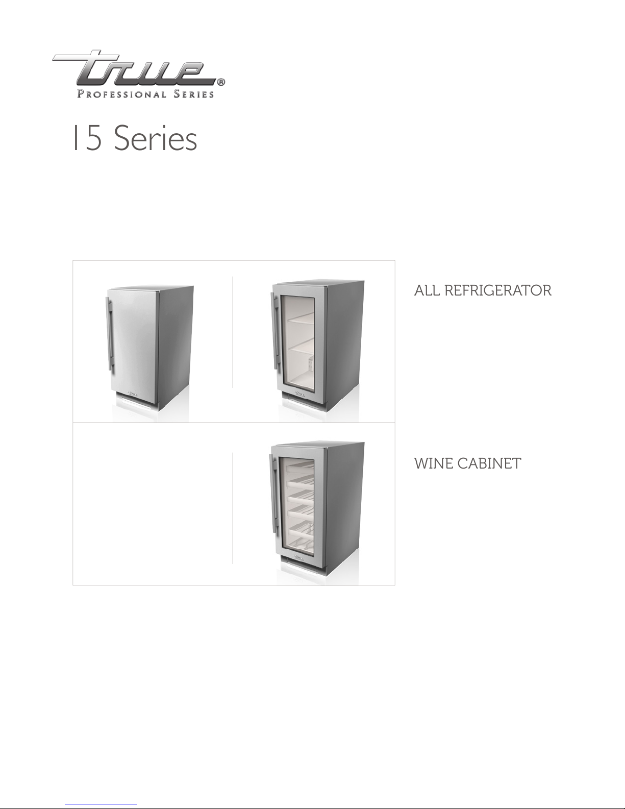
15 Series Installation Guide
ALL REFRIGERATOR
WINE CABINET
Page 2
15 Series
ALL REFRIGERATOR
WINE CABINET
Stainless Solid Door
(SS)
Stainless Glass Door
(SG)
TUR-15-R/L-SS-A
TUR-15-R/L-SG-A
TWC-15-R/L-SG-A
www.true-residential.com
Page 3
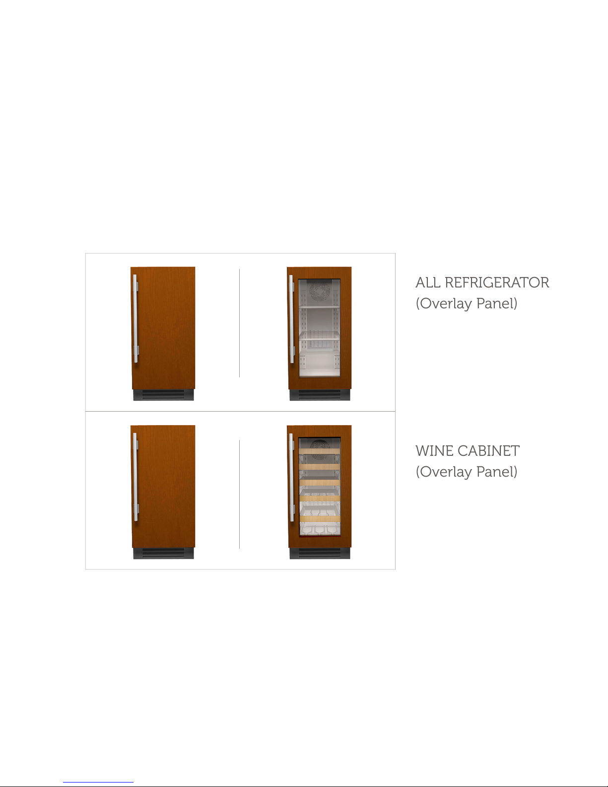
ALL REFRIGERATOR
(Overlay Panel)
WINE CABINET
(Overlay Panel)
Solid Panel Ready
(OP)
Glass Framed Panel Ready
(OG)
TUR-15-R/L-OP-A
TUR-15-R/L-OG-A
TWC-15-R/L-OP-A
TWC-15-R/L-OG-A
Page 4

Thank You
For
Your Purchase
Thank you for purchasing your new True Professional Series unit. For over
65 years, True® has been a leader in commercial refrigeration. No other
refrigeration company has the reputation for being the industry’s best when
it comes to superior quality and service. And while our reputation for quality
reaches across the globe, all of our products are proudly made in the USA.
Respected by the culinary world, True’s unmatched performance is proven
—Our products are carried in some of the most prestigious restaurants and
hotels around the world.
And now, we are pleased to bring this performance to you —crafting products
for your home of the same quality that the world’s best chefs demand in their
kitchens.
This guide will answer most of your questions about the installation of your True
Professional unit. If you have questions that are not answered here, contact
True customer service at 800-325-6152 or info@true-residential.com. Or you
may also visit our website at true-residential.com.
Page 5
15 Series Installation Guide
INDEX
Ownership 1
Safety Precautions 1
Disposal of Old Refrigerator 1
CFC Disposal 1
Uncrating 2
Electrical Specifications 3
Leveling Refrigerator 4
Installing Anti-Tip Brackets 5
Installing the Door Stop 6
Installation Specifications 8-11
Installation Specifications for 15 Series Solid Panel Ready (OP)
and Glass Framed Panel Ready (OG) 12-18
15 Series Cabinet Components and
True Precision Control Operation 20-23
TM
Wine Shelving Adjustment 25
General Maintenance, Replacement Parts, Installation Checklist, FAQs and
Warranty 27
Page 6
OWNERSHIP
To insure that your unit works properly from the
first day, it must be installed properly. (We highly
recommend a trained refrigeration mechanic and
electrician install your True Professional Cabinet.) The
cost of a professional installation is money well spent.
Before you start to install your True Professional
Cabinet, carefully inspect it for freight damage. If
damage is discovered, immediately file a claim with
the delivery freight carrier. True is not responsible for
damage incurred during shipment.
Any questions about the installation please contact
your True dealer or True Technical Service Department
at 1-800-325-6152 (Please have your model and
serial numbers available when you call our Service
Department).
SAFETY PRECAUTIONS
• This refrigerator must be properly installed
and located in accordance with the installation
instructions before it is used.
NOTE: WE STRONGLY RECOMMEND THAT ANY
SERVICING BE PERFORMED BY A QUALIFIED
INDIVIDUAL
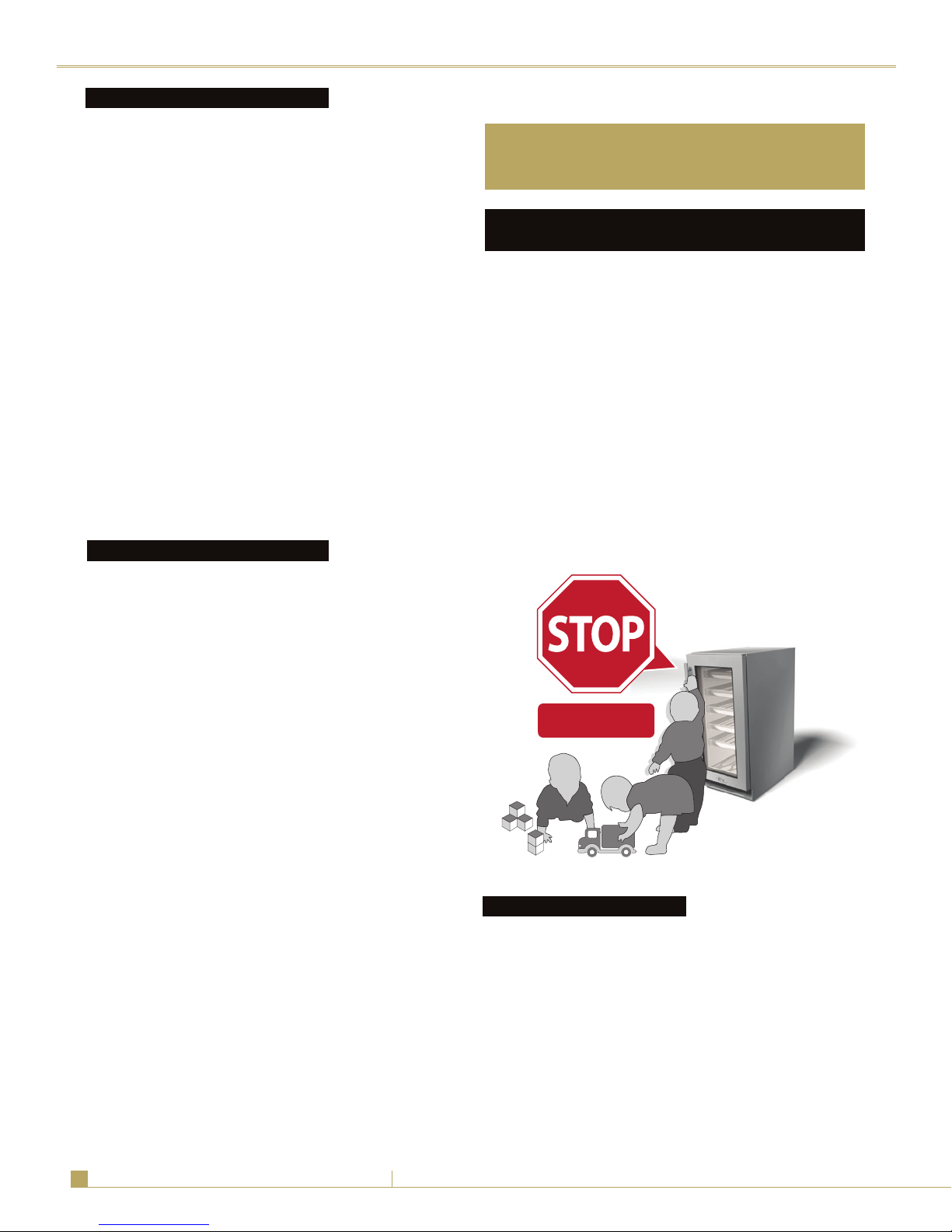
PROPER DISPOSAL OF THE OLD
REFRIGERATOR
Child entrapment and suffocation are not problems
of the past. Junked or abandoned refrigerators are
still dangerous... even if they will sit for “just a few
days”. If you are getting rid of your old refrigerator,
please follow the instructions below to help prevent
accidents.
Before You Throw Away Your Old Refrigerator or
Freezer:
• Take off the doors.
• Leave the shelves in place so that children may not
easily climb inside.
• Do not allow children to climb, stand or hang on
the shelves in the refrigerator. They could damage
the refrigerator and seriously injure themselves.
• Do not store or use gasoline or other ammable
vapors and liquids in the vicinity of this or any
other appliance.
• Keep hands away from the “pinch point” areas
(gaps between the doors and between the doors
and cabinet) small areas are not necessarily safe.
• Unplug the refrigerator before cleaning and
making repairs.
NOTE: We strongly recommend that any
servicing be performed by a qualified individual.
• Setting temperature control to OFF only removes
power from the refrigeration system, it does not
remove power from other circuits. For example,
temperature control and lights.
DANGER!
RISK OF CHILDREN
ENTRAPMENT
CFC DISPOSAL
Your old refrigerator may have a cooling system that
used CFC’s (chlorouorocarbons). CFCs are believed
to harm stratospheric ozone. If you are throwing away
your old refrigerator, make sure the CFC refrigerant is
removed for proper disposal by a qualified service. If
you intentionally release this CFC refrigerant you can
be subject to fines and imprisonment under provisions
of the environment legislation.
1
True Professional 15 Series Installation Guide
Page 7
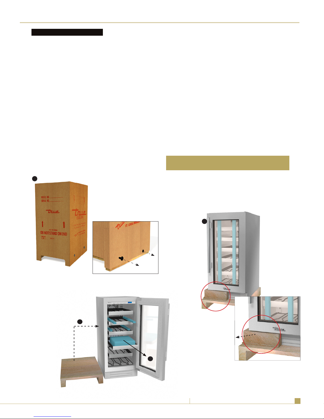
UNCRATING
Tools Required:
• Cutting utensil (utility knife)
• Hammer
• Crowbar
• Phillips head screwdriver
The following procedure is recommended for
uncrating the unit:
MOVE YOUR UNIT AS CLOSE TO THE FINAL
LOCATION AS POSSIBLE BEFORE REMOVING
THE WOODEN SKID.
A. Remove nails securing cardboard box to the
wooden skid. Then discard any outer packaging
(cardboard, clear plastic).
A
Inspect for concealed damage. Again, immediately file
a claim with the freight carrier if there is damage.
B. IMPORTANT: Remove wooden block with Phillips
head screw driver before removing refrigerator
from pallet.
C. Remove skid by carefully lifting the refrigerator off
and place skid aside. Remove clear plastic
coating from cabinet.
D. Open the unit and remove any packing material.
Styrofoam, tape, and any other material used
for shipping purposes.
NOTE: KEYS FOR UNIT ARE PROVIDED WITH
THIS PACKET
B
C
D
True Professional 15 Series Installation Guide
2
Page 8
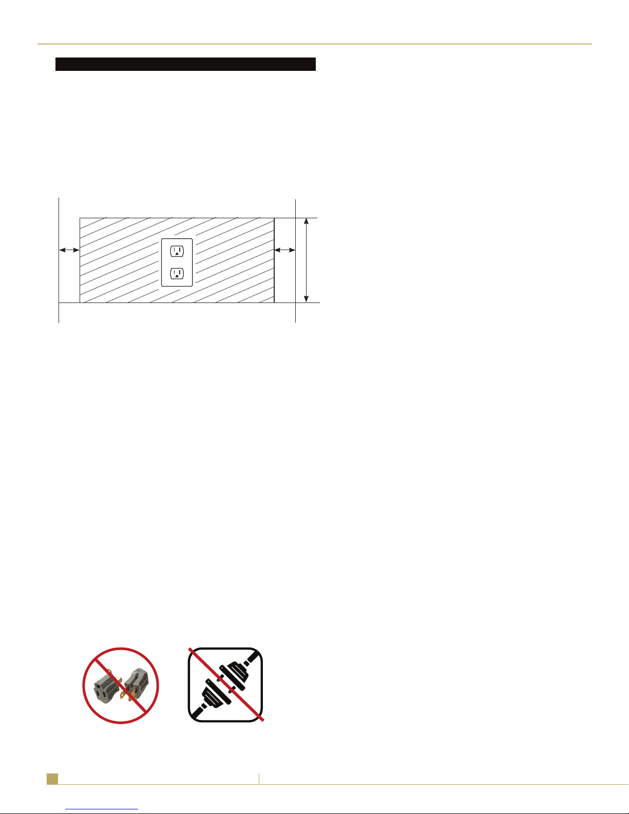
ELECTRICAL SPECIFICATIONS
Do not, under any circumstances, cut or remove the
third (ground) prong from the power cord. For personal
safety, this appliance must be properly grounded.
To minimize the depth of the cutout opening, the
electrical outlet must be positioned as shown below.
Outlet must be ush with wall.
Rear wall of cut out
2” 2” 8”
Before your new unit is connected to a power supply,
check the incoming voltage with a volt meter. If anything
less than 100% of the rated voltage for operation is
noted, correct immediately.
The unit should always be plugged into its own
individual electrical outlet, which has a voltage rating
that matches the rating plate. This provides the best
performance and also prevents overloading house
wiring circuits which could cause a fire hazard from
overheated wires. Never unplug your refrigerator by
pulling on the power cord. Always grip plug firmly
and pull straight out from the outlet.
Repair or replace immediately all power cords that
have become frayed or otherwise damaged. Do not
use a cord that shows cracks or abrasion damage
along its length or at either end. When moving the
refrigerator away from the wall, be careful not to roll
over or damage the power cord.
The power cord of this appliance is equipped with a
3-prong (grounding) plug which mates with a standard
3-prong (grounding) wall outlet to minimize the
possibility of electric shock hazard from this appliance.
A 115V AC, 60 Hz, 15 amp circuit breaker and electrical
supply are required.
Have the wall outlet and circuit checked by a qualified
electrician to make sure the outlet is properly grounded.
If the outlet is a standard 2-prong outlet, it is your
personal responsibility and obligation to have it replaced
with the properly grounded 3 prong wall outlet.
Do not use an extension cord or two prong adaptor.
Electrical ground is required on this appliance.
3
True Professional 15 Series Installation Guide
Page 9
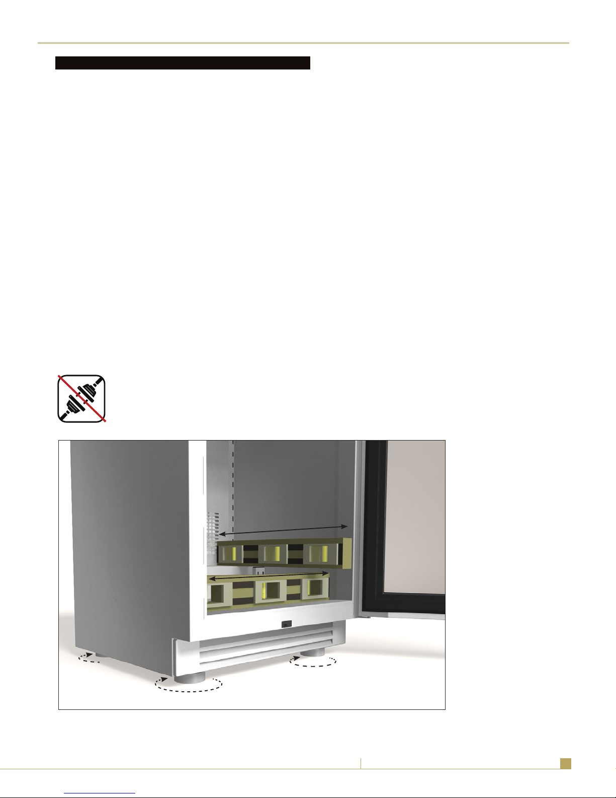
LEVELING REFRIGERATOR
1. Set unit in its final location. Be sure there is adequate ventilation in
your room.
2. Proper leveling of your True unit is critical to operating success
(for non-mobile models). Effective condensate removal and door
operation will be effected by leveling. Adjust leg levelers on the front
and back of the cabinet if it needs to be lowered or raised.
3. The unit should be leveled from the interior of the unit front to back
and side to side with a level. If the refrigerator is not level adjust the
stainless steel leg levelers. The leg levelers can be adjusted by turning
to reach the desired leveling height as shown in the illustration below.
4. Free plug and cord from back of cooler (do not plug in).
5. The unit should be placed close enough to the electrical supply so
that extension cords are never used.
6. Once installed in final location, inser t toe kick by clipping in place.
WARNING: COMPRESSOR WARRANTIES ARE VOID IF
THE UNIT IS MORE THAN 7 FT. (2.1M) FROM PLUG-IN
CONNECTION OR IF AN EXTENSION CORD IS USED.
True Professional 15 Series Installation Guide
4
Page 10
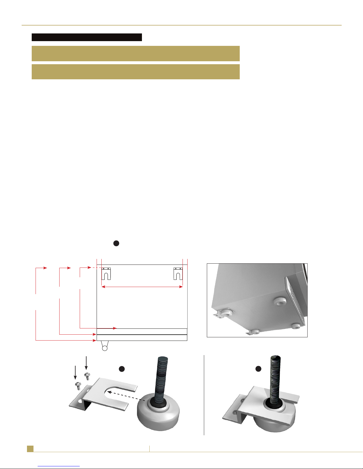
INSTALLING ANTI-TIP BRACKETS
ALL FREE STANDING UNITS MUST HAVE THE ANTI-TIP BRACKETS
INSTALLED.
TIP OVER HAZARD: A CHILD OR ADULT CAN TIP THE REFRIGERATOR
AND MAY CAUSE PROPERTY OR BODILY HARM.
To prevent this the anti-tip brackets need to be installed.
Reconnect the anti-tip bracket if the product is moved.
Failure to follow these instructions can result in property
or bodily harm.
Read all installation instructions first. Install the anti-tip
brackets to hold both rear legs of the unit. Follow these
steps to secure the brackets to the oor before moving
the unit into final operating position.
Contact a qualied oor covering installer for the best
procedure of drilling mounting holes through your type
of oor covering.
BEFORE MOVING UNIT TAKE PRECAUTIONS TO
PROTECT THE FLOOR COVERING.
A
ANTI-TIP BRACKET LOCATOR - TOP VIEW
27/32” 27/32”
Back of the unit
A. Determine the location of the unit. From the front
of the determined location of the lower louver grill
measure back 20
1/2
”. From the determined side of
the unit measure over 27/32”. This is where the back
and outer side of the bracket should sit. Using the
bracket as a template mark the holes for drilling.
B. To mount the anti-tip bracket to wood oor, drill
pilot holes for each of the bracket holes. To mount
the anti-tip bracket to concrete or ceramic oor
use a masonry bit to drill pilot holes. Align anti-tip
bracket holes with the holes in the oor. Fasten anti-
tip bracket with screws provided using the brass
colored screw for wood, or blue colored masonry
screw for concrete.
C. Move unit into final position making sure rear leveling
legs slide into the anti-tip brackets.
20 1/2”
Overlay Panel
22 1/32”
5
22 25/32”
True Professional 15 Series Installation Guide
13 3/16”
Cabinet Front
B
C
Page 11
INSTALLING THE DOOR STOP
All units are provided with an optional door stop. When installed, the door stop will restrict the door from
opening past approximately 120º to prevent damage to surrounding cabinets. To install the door stop, use the
2 screws provided and secure the bracket to the bottom of the door on the same side as the hinge.
Hinge
Door stop
Cabinet door
Door stop
installed
Cabinet grill
True Professional 15 Series Installation Guide
6
Page 12

NOTES
7
True Professional 15 Series Installation Guide
Page 13

True Professional 15 Series
Installation Specifications
True Professional 15 Series Installation Guide
8
Page 14

INSTALLATION SPECIFICATIONS-STAINLESS SOLID & GLASS DOOR
ALL REFRIGERATOR
WINE CABINET
TUR-24R/L-SS-A TUR-24R/L-SG-A TWC-24R/L-SG-A
7/8
”
FRONT
VIEW
1/8
4
”
29
3/4
”
3/4
3
”
Dimensions may vary by ± 1/8”
7/8
23
SIDE
VIEW
”14
34
1/4
TOP
VIEW
”
7/8
37
”
1/4
16
”
7/8
1
”
9
True Professional 15 Series Installation Guide
Page 15

INSTALLATION SPECIFICATIONS-STAINLESS SOLID & GLASS DOOR
True’s Stainless Solid and Glass Door units are designed to be inserted into a cabinet
opening or free standing. Below are recommended dimensions for rough opening.
ROUGH
OPENING
HEIGHT
1/2
34
”
ROUGH
OPENING
DEPTH
24”
ROUGH
OPENING
WIDTH
15”
Front view
of unit
between
cabinets
True Professional 15 Series Installation Guide
10
Page 16

INSTALLATION SPECIFICATIONS - OUTDOOR
True’s stainless steel cabinets are UL rated for use in outdoor settings.
In outdoor locations where the ambient temperature regularly exceeds 95˚F, it is recommended
to vent the rear of the cut out opening in the area shown below for optimum performance. The
recommended cut out size is 4” x 10”.
ROUGH
OPENING
HEIGHT
1/2
34
”
8”
8”
ROUGH
OPENING
DEPTH
24”
ROUGH
OPENING
WIDTH
15”
11
True Professional 15 Series Installation Guide
Page 17

True Professional 15 Series
Installation Specifications for
Solid Panel Ready (OP)
Glass Framed Panel Ready (OG)
True Professional 15 Series Installation Guide
12
Page 18

INSTALLATION SPECIFICATIONS-SOLID & GLASS FRAMED PANEL READY
ALL REFRIGERATOR
WINE CABINET
NOTE: These units are shown with optional panel/handle provided by others
TUR-15-R/L-OP-A TUR-15-R/L-OG-A
TWC-15-R/L-OP-A TWC-15-R/L-OG-A
13
True Professional 15 Series Installation Guide
Page 19

14
7/8
7/8
23
”
3/4
”
23
1/8
”
”
* Including 3/4” thick panel (provided by others)
TOP
FRONT
VIEW
1/8
4
”
7/8
14
”
29
3/4
”
3/4
*3
”
3/4
”
SIDE
VIEW
7/8
23
1/8
23
1/4
34
”
”
”
VIEW
TOP
FRONT
VIEW
29
3/4
”
VIEW
34
1/4
”
SIDE
VIEW
37
16
37
7/8
1/4
7/8
”
”
”
1/4
16
37
16
7/8
1/4
”
”
”
1/8
4
”
7/8
14
”
*3
3/4
3/4
”
7/8
23
”
”
23
1/8
”
TOP
FRONT
VIEW
1/8
4
”
29
3/4
”
3/4
*3
”
SIDE
VIEW
34
1/4
”
VIEW
True Professional 15 Series Installation Guide
14
Page 20

14 5/8"
INSTALLATION SPECIFICATIONS-SOLID & GLASS FRAMED PANEL READY...Continuation
CUSTOM PANEL INSTALLATION
Solid Door
7 5/16"
29/32"
29/32"
6 1/8"
14 7/8"
BACK VIEW OF SOLID DOOR
23 5/8"
29 23/32"
OVERLAY PANEL
29/32"
MODELS
Solid Door Glass Door
TUR-15-R/L-OP-A TUR-15-R/L-OG-A
TWC-15-R/L-OP-A TWC-15-R/L-OG-A
7/8
23
3/4
”
1/8
4
”
3/4
*3
”
1/8
23
SIDE
VIEW
”
”
1/4
34
”
29/32"
Solid & Glass Door Panel Dimensions
Door Panel Width
Door Panel Height
Door Panel Depth
5/8
14
1/2
29
3/4” max
Glass Door
14 5/8"
7 5/16"
29/32"
29/32"
6 1/8"
29/32"
”
23 5/8"
14 7/8"
BACK OF GLASS DOOR
OVERLAY PANEL
25 23/32"
VIEWABLE
AREA
”
29 23/32"
15
True Professional 15 Series Installation Guide
29/32"
10 5/8"
VIEWABLE
AREA
Page 21

INSTALLATION SPECIFICATIONS-SOLID & GLASS FRAMED PANEL READY...Continuation
True’s units with Solid and Glass Framed Panel are designed to be inserted into a cabinet opening.
ROUGH
OPENING
HEIGHT
1/2
34
”
ROUGH
OPENING
DEPTH
24”
ROUGH
OPENING
WIDTH
15”
Front view
of unit
between
cabinets
True Professional 15 Series Installation Guide
16
Page 22

SOLID & GLASS OVERLAY PANEL INSTALLATION
Tools Needed:
• Phillips Screwdriver
• 3/8” Wrench
• 1/8” Drill Bit
• Ten (10) Screws #6
SEE PAGES 14-16 FOR OVERLAY PANEL DIMENSIONS
BEFORE INSTALLING.
FOR EASY OVERLAY INSTALLATION REFRIGERATOR
DOOR REMOVAL IS REQUIRED.
NOTE: DO NOT INSTALL A SOLID PANEL ON A
GLASS DOOR. THIS MAY CAUSE MOISTURE TO FORM
BEHIND THE PANEL RESULTING IN DAMAGE.
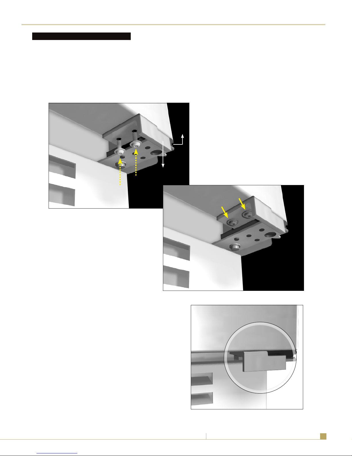
1. Open front door and pull grill forward to remove.
2. To remove door back out two bottom hinge screws
with a 3/8” wrench. Secure door while removing
screws. Remove two Phillips screws from the top
hinge. Save all these screws for later reinstall.
1
2
Remove
screws from
top and
bottom hinge
3. Lay door on a safe solid surface. If retrofitting glass
door model be careful not to damage glass. Lay
cardboard or other safe material down before working
on the door.
4. Remove door gasket from the inside of the door
frame. Place gasket to the side for later reinstall.
5. There are pre marked areas on the front of the door.
Drill these pre marked holes with 1/8” drill bit. Make
sure to go all the way through the door.
NOTE: IF HANDLE IS BEING USED ON OVERLAY
INSTALL IT BEFORE STEP 8 (See Image A). FOR BEST
INSTALLATION, SCREWS ATTACHING HANDLE
SHOULD BE RECESSED.
6. It is recommended to clamp the door front on top
of the overlay before drilling pilot holes and installing
anchor screws. The clamp ensures the overlay panel
and door stay aligned with each other while installing.
Once panel is clamped in place, pilot holes may be
drilled into the panel from the rear side of the door.
43
5
17
True Professional 15 Series Installation Guide
Page 23

SOLID & GLASS OVERLAY PANEL INSTALLATION...Continuation
7. Once all holes are pre drilled use the appropriate
specified screws to secure the overlay panel onto the
front of the refrigerator door.
8. Reinstall all components in reverse order. Door
gasket snaps back into place. Overlay panel and door
stay aligned with each other while installing.
Image A
Door Layers - General View
Gasket Door
Overlay Panel
6
7
8
Handle
Reinstall
screws on top
and bottom
hinge
Solid Overlay Panel Glass Overlay Panel
True Professional 15 Series Installation Guide
1818
Page 24

NOTES
19
True Professional 15 Series Installation Guide
Page 25

True Professional 15 Series
True Precision Control Operation
TM
and Cabinet Components
True Professional 15 Series Installation Guide
20
Page 26

TRUE PRECISION CONTROL OPERATION
TM
Power Button
1
Activates Accent Light
2
Controls for Compar tment
3
4321
Display for Temperature
4
Additional Control Features:
Power + = Offset mode
+ = Lock / Unlock Keypad
+ Light = Sabbath Mode
+ Light = Color Change
Power + Light = Showroom Mode
Power + = Alarm
21
21
True Professional 15 Series Installation Guide
True Professional 15 Series Installation Guide
Page 27

TRUE ALL REFRIGERATOR COMPONENTS
Location of Serial Tag
Adjustable
Spill Proof
Glass Shelves (2)
Removable Kickplate
for easy cleaning
Door Lock
True Professional 15 Series Installation Guide
True Professional 15 Series Installation Guide
22
22
Page 28

TRUE WINE CABINET COMPONENTS
Location of Serial Tag
Adjustable
Slide Out
Wine Shelves (5)
Floor Wine Cradle (1)
Removable Kickplate
for easy cleaning
Door Lock
23
True Professional 15 Series Installation Guide
True Professional 15 Series Installation Guide
Page 29

NOTES
Page 30

True Professional 15 Series
Shelving Adjustments
25
True Professional 15 Series Installation Guide
Page 31

SHELVING ADJUSTMENTS
WINE SHELVES
The glide out wine shelves in TWC models consist of
3 pieces. These pieces are the wire wine rack and 2
mounting bracket/glide assemblies (one for the hinge
side and one for the non-hinge side).
To remove the wine shelf, pull up on the front of the wine
rack and it will separate from the 2 mounting brackets.
The 2 mounting brackets may now be removed from the
pilasters by lifting straight up then pulling the brackets out
of the pilasters.
Note when reinstalling the brackets, the bracket with the
larger vibration bumper must be installed on the same
side of the cabinet as the door hinge. When reinstalling
the wine rack, be sure that the back of the rack hooks
underneath the tab on the glide.
The tab on the front of the glide must also fit securely in
the gap between the handle and the rack (see illustration).
If the fit is too tight, you may need to loosen the screws
on the back of the handle to increase the gap.
The wine shelves are held securely by the anti-vibration
bumpers. If there is too much play side-to-side, tighten
the bumpers against the compartment walls by rotating
with your fingers.
anti-vibration
bumpers
True Professional 15 Series Installation Guide
26
Page 32

True Professional 15 Series
General Maintenance
Replacement Parts
Installation Checklist
Frequently Asked Questions
Warranty
27
True Professional 15 Series Installation Guide
Page 33

GENERAL MAINTENANCE
Keeping the condenser coil clean will minimize required service and lower electrical cost.
The condenser coil is accessible from the front..
The condenser coil should be cleaned by removing dust and other build-up from the tube
assembly with vacuum or a cleaning rag.
When properly cleaned you should be able to see through the tube assembly.
Warranty does not cover cleaning the condenser coil.
REPLACEMENT PARTS
True maintains a record of the cabinet serial number for your unit If at any time during the life
of your unit, a part is needed, you may obtain that part by furnishing the model number and
serial number to the company from whom you purchased the cooler. For replacement par ts
contact the dealer from whom you purchased the refrigerator or call True parts depar tment at
1-800-424-TRUE. Inquires can be sent to the following address:
Attention Parts Department
True Manufacturing
2001 East Terra Lane
O’Fallon, MO 63366-4434
INSTALLATION CHECKLIST
To ensure a proper installation, this checklist should be completed upon installation to ensure that no
part of the process has been overlooked.
Have all packaging materials been removed?
Is the unit operating properly? If not, is the unit plugged in? Is the control turned on?
Have the anti-tip brackets been installed securely and are they properly engaging the unit?
Is the unit leveled properly with all leveling legs making contact with the oor? Has the kick plate
been installed?
Are panels attached securely and properly aligned? (Overlay cabinets only).
Does the customer understand the unit’s operation?
Has the customer been given the keys and literature package?
Have stainless steel surfaces been inspected for any imperfections? This is to be done by the
authorized True dealer or installer with the customer, upon completion of installation. Stainless
steel doors, handles and shelves are covered by a limited 30-day warranty for cosmetic defects.
True Professional 15 Series Installation Guide
28
Page 34

FREQUENTLY ASKED QUESTIONS
Q. How do I adjust the temperature?
A. Refer to True Precision Control Operation on page 20.
Q. Why isn’t my unit cooling properly?
A. Check to see that there are no obstructions to the condenser coil (behind front grill).
Confirm that the condenser area is clean.
Q. How do I adjust or remove a shelf from my current configuration?
A. Refer to shelving operation on page 26.
Q. Why is there warm air coming from the bottom/front of the refrigerator
(grill/kickplate area)?
A. This is normal as heat dissipation is par t of the refrigeration cycle.
Q. Why is there condensation forming on the inside or outside of the unit?
A. In climates with higher humidity or when the cabinet is placed in an outdoor setting,
condensation may form on the unit and is considered normal. Leaving the door open
for a long period of time will also cause excess condensation.
Q. What are the preset limits for the high temperature alarm?
A. The electronic control will monitor temperatures and activate an aler t if unsafe
product temperatures are present for more than 60 minutes. For dual zone wine
chillers, the alarm will activate if the temperature deviates more than 10˚F or 6ºC
degrees warmer or colder than the set point. On dual zone wine chillers, this feature
is only active if the door ajar alarm mode is active. It is disabled during sabbath mode.
29
True Professional 15 Series Installation Guide
Page 35

WARRANTY
LIMITED 30 DAY COSMETIC WARRANTY
Stainless steel doors, handles, and shelves are warranted to be free from defective materials or workmanship for a period of thirty (30) days
from the date of original retail purchase. Any defects must be reported to the selling dealer within thirty (30) days from the date of original
retail purchase. This limited warranty excludes any type of freight / concealed damage.
TWO YEAR PARTS & LABOR WARRANTY
TRUE warrants to the original purchaser of every new TRUE refrigerated unit, the cabinet and all parts thereof, to be free from defects in
material or workmanship under normal and proper use and maintenance as specified by TRUE and upon proper installation and start-up in
accordance with the instruction packet supplied with each TRUE unit. TRUE’s obligation under this warranty is limited to a period of two (2)
years from the date of original installation or twenty seven (27) months after shipment date from TRUE, whichever occurs first.
FIVE YEAR SEALED SYSTEM WARRANTY
TRUE warrants its hermetically sealed system: compressor, evaporator coil, condenser coil, drier, metering device and connecting tubing to be
free from defects in both material and workmanship under normal and proper use and maintenance ser vice for a period of five (5) years from
the date of original installation but not to exceed sixty three (63) months after shipment from the manufacturer, whichever occurs first.
TERMS APPLICABLE TO EACH WARRANTY
Any part covered under the above warranties that is determined by TRUE to have been defective within the time frame is limited to the repair
or replacement, including labor charges, of defective parts or assemblies. The labor warranty shall include standard straight time labor charges
only and reasonable travel time, as determined by TRUE.
WARRANTY CLAIMS
All claims for labor or parts must be made directly through TRUE. All claims should include: model number and serial number of cabinet, proof
of purchase, and date of installation. In case of warranted compressor, the compressor model tag must be returned to TRUE along with the
above listed information.
WHAT IS NOT COVERED BY THIS WARRANTY
TRUE’s sole obligation under this warranty is limited to either repair or replacement of parts, subject to the additional limitations below. This
warranty neither assumes nor authorizes any person to assume obligations other than those expressly covered by this warranty.
NO CONSEQUENTIAL DAMAGES. TRUE is not responsible for economic loss, profit loss; or special, indirect or consequential damages,
including without limitation, losses or damages arising from food or product spoilage claims whether or not on account or refrigeration failure.
WARRANTY IS NOT TRANSFERABLE. This warranty is not assignable and applies only in favor of the original purchaser/user to whom
delivered. Any such assignment or transfer shall void the warranties herein made and shall void all warranties, express or implied, including any
warranty or merchantability or fitness for a par ticular purpose.
IMPROPER USAGE. TRUE assumes no liability for parts or labor coverage for component failure or other damages resulting from improper
usage or installation or failure to clean and/or maintain product as set forth in the warranty packet provided with the unit.
ALTERATION OR NEGLECT. TRUE is not responsible for the repair or replacement of any parts that TRUE determines have been subjected
after the date of manufacture to alteration, neglect, abuse, misuse, accident, damage during transit or installation, re, ood, or act of God.
IMPROPER ELECTRICAL CONNECTIONS. TRUE is not responsible for the repair or replacement of failed or damaged components
resulting from electrical power failure, high or low voltage, use of extension cords, or improper grounding of the unit.
NO IMPLIED WARRANTY. There are no other warranties, expressed, implied or statutory except the 30 day cosmetic, 2 year parts and
labor and five year sealed system warranty as described above. These warranties are exclusive and in lieu of all other warranties, including
implied warranty and merchantability or fitness for a par ticular purpose, There are no warranties which extend beyond the description on the
face hereof.
Some states do not allow the exclusion or limitation of consequential damages or a limitation on how long an implied warranty lasts, so the
above exclusion or limitation may not apply to you. This warranty gives you specific legal rights and you may have other rights that vary from
state to state.
OUTSIDE U.S./CANADA. This warranty does not apply to, and TRUE is not responsible for, any warranty claims made on products sold or
used outside the United States or Canada.
True Professional 15 Series Installation Guide
30
Page 36

ALL REFRIGERATOR
15 Series Installation Guide
WINE CABINET
KEY PACKET LOCATION
phone: 888.616.8783 parts: 800.424.8783
2001 East Terra Lane
O’Fallon, MO 63366
email: info@true-residential.com
web: true-residential.com
True Professional 15 Series Installation Guide
961365
AD 9.12
31
 Loading...