

True TUR-24-R/L-OG-B, TUF-24D-OP-B, TBC-24-R/L-OP-B, TBC-24-R/L-OG-B, TWC-24-R/L-OP-B Install Manual
...Page 1

13 - 27
i n s t a l l a t i O n s p e c i f i c a t i O n s
f O r s O l i D p a n e l r e a D y ( O p ) a n D
g l a s s f r a m e D pa n e l r e a D y ( O g )
PRESERVE THE MOMENT
®
15 INCH & 24 INCH INSTALL GUIDE
13
Page 2
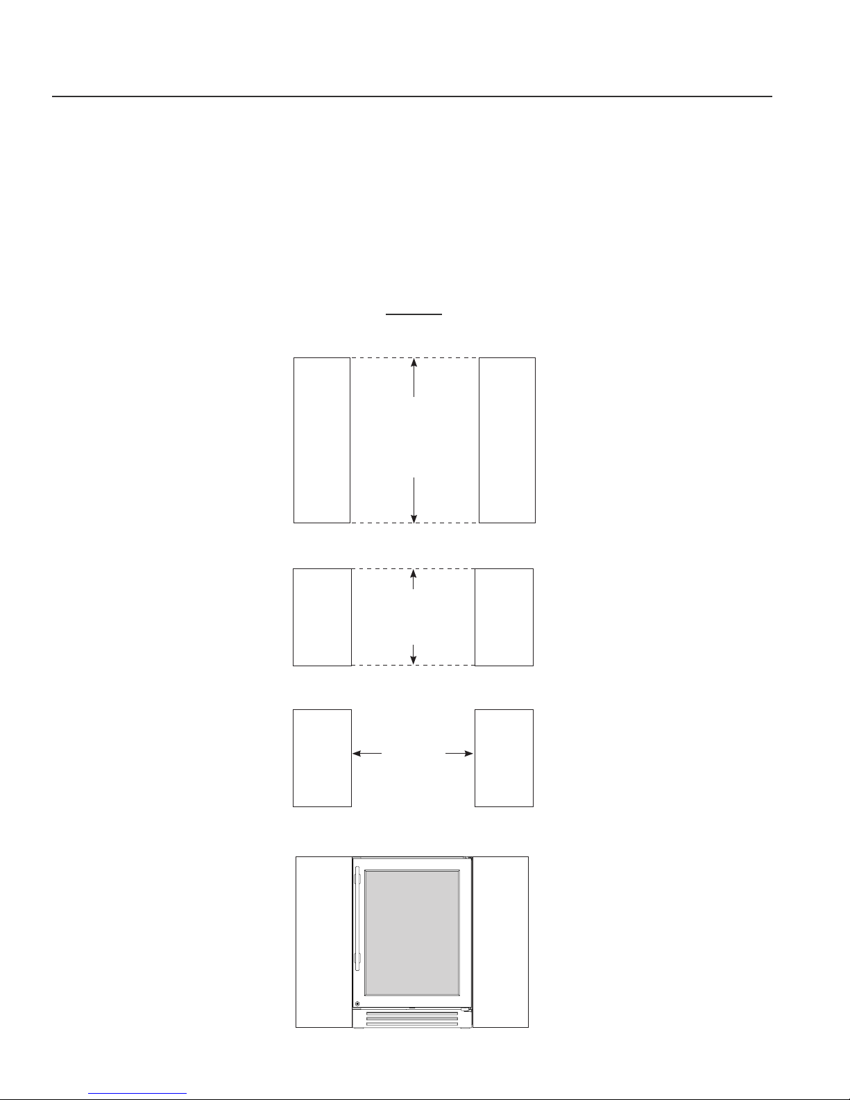
24 INCH INSTALLATION SPECIFICATIONS SOLID (OP) AND GLASS FRAMED PANEL (OG)
True’s 24 inch units with Solid and Glass Framed Panels are designed to be inserted into a cabinet opening
or free standing. Below are recommended dimensions for rough opening.
TRUE’S CABINETS ARE UL RATED FOR USE IN OUTDOOR SETTINGS.
IN OUTDOOR LOCATIONS WHERE THE AMBIENT TEMPERATURE REGULARLY EXCEEDS 95˚F, IT IS RECOMMENDED
TO VENT THE REAR OF THE CUT OUT OPENING IN THE AREA SHOWN BELOW FOR OPTIMUM PERFORMANCE.
THE RECOMMENDED CUT OUT SIZE IS 4" X 10".
24 INCH
Rough Opening
HEIGHT
1/2
34
"
Rough Opening
DEPTH
24"
Rough Opening
WIDTH
24"
23 7/
"
8
Fro nt view
of unit
between
cabinets
29 3/
"
4
TRUE RESIDENTIAL
14
®
4 1/
"
8
Page 3
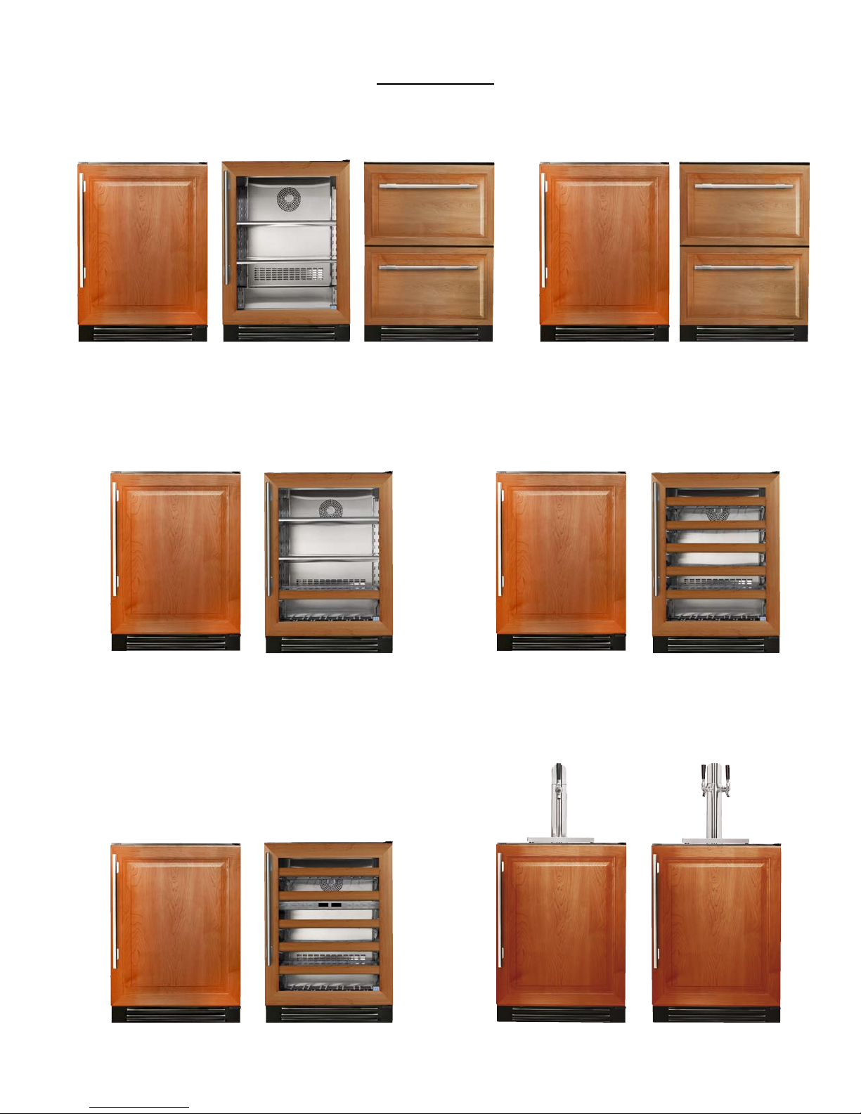
24 INCH
ALL REFRIGERATOR FREEZER
TUR-24-R/L-OG-BTUR-24-R/L-OP-B TUF-24-R/L-OP-BTUR-24D-OP-B TUF-24D-OP-B
BEVERAGE CENTER
TBC-24-R/L-OP-B
DUAL ZONE WINE CABINET
TBC-24-R/L-OG-B
WINE CABINET
TWC-24-R/L-OP-B TWC-24-R/L-OG-B
BEVERAGE DISPENSER
TWC-24DZ-R/L-OP-B
TWC-24DZ-R/L-OG-B
TUR-24BD-R/L-OP-B TUR-24DD-R/L-OP-B
15 INCH & 24 INCH INSTALL GUIDE
15
Page 4
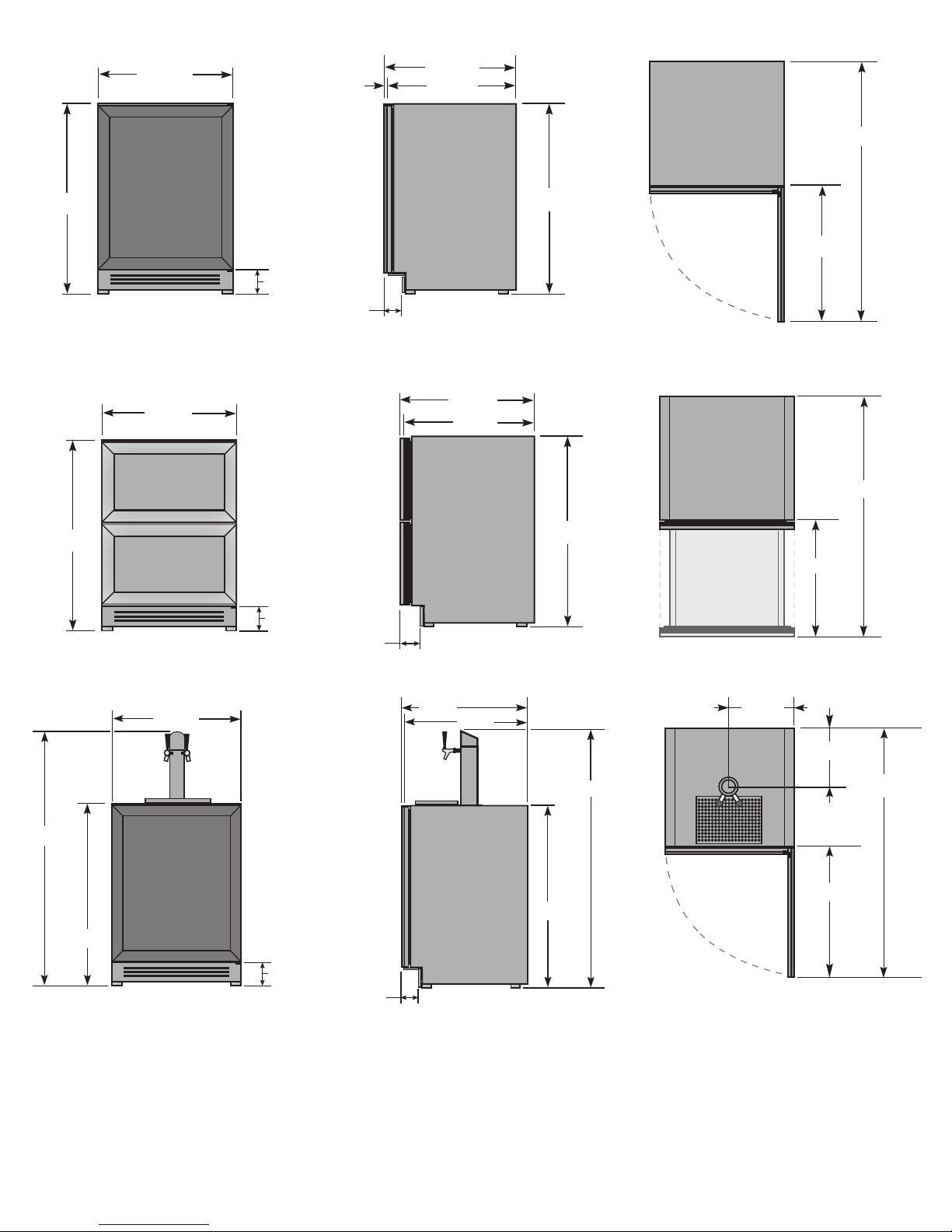
23 7/8"
23 7/8"
3
/4"
23 1/8"
46 7/8"
34 1/4"
34 1/4"
23 7/8"
34 1/4"
25 1/4"
4 1/8"
3 3/4"
23 7/8"
23 1/8"
42 5/8"
34 1/4"
21"
4 1/8"
3 3/4"
50"
34 1/4"
23 7/8"
4 1/8"
3 3/4"
23 7/8"
23 1/8"
50"
34 1/4"
24" SINGLE TAP UNIT ACCOMMODATES (1) SHORT 1/4 BARREL, (1) SLIM
1/4 BARREL, OR (1) 1/6 BARREL. 24" DUAL TAP UNIT ACCOMMODATES
(2) 1/6 BARRELS OR (1) SLIM 1/4 BARREL AND (1) 1/6 BARREL.
*
INCLUDING 3/4" THICK PANEL (PROVIDED BY OTHERS)
1
DIMENSIONS MAY VARY BY ±
/8"
11 7/8"
10 1/4"
46 7/8"
25 1/4"
TRUE RESIDENTIAL
16
®
Page 5
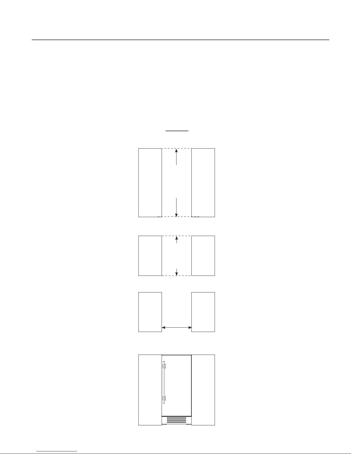
15 INCH INSTALLATION SPECIFICATIONS SOLID (OP) AND GLASS FRAMED PANEL (OG)
True’s 15 inch units with Solid and Glass Framed Panels are designed to be inserted into a cabinet opening
or free standing. Below are recommended dimensions for rough opening.
TRUE’S CABINETS ARE UL RATED FOR USE IN OUTDOOR SETTINGS.
IN OUTDOOR LOCATIONS WHERE THE AMBIENT TEMPERATURE REGULARLY EXCEEDS 95˚F, IT IS RECOMMENDED
TO VENT THE REAR OF THE CUT OUT OPENING IN THE AREA SHOWN BELOW FOR OPTIMUM PERFORMANCE.
THE RECOMMENDED CUT OUT SIZE IS 4" X 10".
15 INCH
Rough
Opening
HEIGHT
1/2
34
"
Rough
Opening
DEPTH
24"
Rough
Opening
WIDTH
15"
Fro nt
view of
unit
between
cabinets
15 INCH & 24 INCH INSTALL GUIDE
17
Page 6

15 INCH
ALL REFRIGERATOR
TUR-15-R/L-OP-B TUR-15-R/L-OG-B
WINE CABINET
TWC-15-R/L-OP-B TWC-15-R/L-OG-B
BEVERAGE DISPENSER
TUR-15BD-R /L-OP-B
TRUE RESIDENTIAL
18
®
Page 7

14 7/8"
23 7/8"
37 7/8"
50"
1
/4"
34 1/4"
16 1/4"
4 1/8"
3 3/4"
14 7/8"
23 7/8"
23 1/8"
50"
7 1/2"
10 1/4"
37 7/8"
34 1/4"
34 1/4"
4 1/8"
3 3/4"
15" SINGLE TAP UNIT ACCOMMODATES
(1) SLIM 1/4 BARREL OR (1) 1/6 BARREL.
*
INCLUDING 3/4" THICK PANEL (PROVIDED BY OTHERS)
1
DIMENSIONS MAY VARY BY ±
/8"
16 1/4"
15 INCH & 24 INCH INSTALL GUIDE
19
Page 8

CUSTOM PANEL INSTALLATION - SOLID DOOR REFRIGERATOR / FREEZER
Overlay units can be fitted with custom panels to match adjacent cabinetry. Two specification options for panels
sizes are given in these instructions for overlay units: Standard overlays and Integrated Panels. The standard
overlay panel dimensions fully cover the provided appliance door. The integrated panel options extend above the
door and conceal the hinge assembly to match full overlay cabinet doors. See pictures below for reference.
STANDARD OVERLAY PANEL
INTEGRATED OVERLAY PANEL
TRUE RESIDENTIAL
20
®
Page 9

CUSTOM PANEL INSTALLATION - SOLID DOOR REFRIGERATOR / FREEZER
3/4"
A
B
5/8"
14 5/8"
3/4"
A
B
5/8"
14 5/8"
3/4"
A
B
5/8"
23 5/8"
3/4"
A
B
5/8"
23 5/8"
B
14 5/8"
3/4"
A
B
5/8"
9/16"
DETAIL A
SCALE 1 : 1
1"
DETAIL B
SCALE 1 : 1
14 5/8"
B
14 5/8"
STANDARD OVERLAY PANEL
SOLID DOOR 24 INCH 15 INCH
DOOR PANEL WIDTH 23
DOOR PANEL HEIGHT 29
5/8
" 14
23/32
" 29
DOOR PANEL DEPTH 3/4" max 3/4" max
DOOR PANEL WEIGHT 10 lb. max 10 lb. max
RAIL STYLE DIMENSION 2” min 2” min
5/8
23/32
INTEGRATED OVERLAY PANEL
SOLID DOOR 24 INCH 15 INCH
DOOR PANEL WIDTH 23
DOOR PANEL HEIGHT 30
5/8
" 14
1/8
" 30
DOOR PANEL DEPTH 3/4" max 3/4" max
DOOR PANEL WEIGHT 10 lb. max 10 lb. max
RAIL STYLE DIMENSION 2” min 2" min
5/8
1/8
23 5/8"
14 5/8"
"
"
23/32
30 1/8"
24 INCH
23/32
30 1/8"
"
FRONT
29
"29
15 INCH
FRONT
23 5/8"
14 5/8"
"
"
15 INCH
FRONT
30 1/8"
24 INCH
FRONT
30 1/8"
3/4"
A
B
23 5/8"
14 5/8"
B
15 INCH24 INCH
BACKBACK
15 INCH & 24 INCH INSTALL GUIDE
1"
DETAIL B
SCALE 1 : 1
21
Page 10

CUSTOM PANEL INSTALLATION - GLASS DOOR REFRIGERATOR
30 1/8"
3/4"
A
B
5/8"
14 5/8"
30 1/8"
3/4"
A
B
5/8"
14 5/8"
3/4"
A
B
5/8"
23 5/8"
3/4"
A
B
5/8"
23 5/8"
B
14 5/8"
3/4"
A
B
5/8"
9/16"
DETAIL A
SCALE 1 : 1
1"
DETAIL B
SCALE 1 : 1
14 5/8"
B
14 5/8"
STANDARD OVERLAY PANEL
SOLID DOOR 24 INCH 15 INCH
DOOR PANEL WIDTH 23
DOOR PANEL HEIGHT 29
5/8
" 14
23/32
" 29
DOOR PANEL DEPTH 3/4" max 3/4" max
DOOR PANEL WEIGHT 10 lb. max 10 lb. max
RAIL STYLE DIMENSION 2” min 2” min
VIEWABLE AREA WIDTH 19
VIEWABLE AREA HEIGHT 25
5/8
” 10
23/32
” 25
5/8
23/32
5/8
23/32
INTEGRATED OVERLAY PANEL
SOLID DOOR 24 INCH 15 INCH
DOOR PANEL WIDTH 23
DOOR PANEL HEIGHT 30
5/8
" 14
1/8
” 30
DOOR PANEL DEPTH 3/4" max 3/4" max
DOOR PANEL WEIGHT 10 lb. max 10 lb. max
RAIL STYLE DIMENSION 2” min 2” min
5/8
VIEWABLE AREA WIDTH 19
VIEWABLE AREA HEIGHT 25
” 10
23/32
” 25
5/8
1/8
5/8
23/32
23 5/8"
14 5/8"
"
"
"29
15 INCH
FRONT
24 INCH
29
23/32
23/32
30 1/8"
"
FRONT
”
”
23 5/8"
14 5/8"
"
”
15 INCH
FRONT
30 1/8"
24 INCH
FRONT
”
”
3/4"
A
TRUE RESIDENTIAL
22
B
®
23 5/8"
B
14 5/8"
15 INCH24 INCH
BACKBACK
1"
DETAIL B
SCALE 1 : 1
Page 11

CUSTOM PANEL INSTALLATION - DRAWER REFRIGERATOR / FREEZER
STANDARD OVERLAY PANEL
DRAWER PANEL WIDTH 23
DRAWER PANEL HEIGHT 14
5/8
11/1 6
"
DRAWER PANEL DEPTH 3/4" max
5/8
23
"
TOP DRAWER -
REFRIGERATOR
BOTTOM DRAWER -
REFRIGERATOR
11/16
14
”
11/16
14
”
"
5/8
23
"
TOP & BOTTOM DRAWER -
FREEZER
11/16
14
”
SPEC SAME PANEL FOR TOP & BOTTOM FREEZER DRAWERS.
FOR BOTTOM DRAWER ROTATE PANEL 180º.
INTEGRATED OVERLAY PANEL
DRAWER PANEL WIDTH 23
TOP DRAWER PANEL HEIGHT 15
BOTTOM DRAWER PANEL HEIGHT 14
DRAWER PANEL DEPTH 3/4" max
5/8
23
"
TOP DRAWER -
REFRIGERATOR
BOTTOM DRAWER -
REFRIGERATOR
1/8
15
11/16
14
1/8
11/1 6
”
”
5/8
"
"
”
5/8
23
"
TOP DRAWER -
REFRIGERATOR
BOTTOM DRAWER -
REFRIGERATOR
1/8
15
”
11/16
14
”
NOTE: TOP DRAWER WILL EXTEND ABOVE PROVIDED APPLIANCE FRONT
15 INCH & 24 INCH INSTALL GUIDE
23
Page 12

SOLID (OP) AND GLASS FRAMED PANEL (OG) INSTALLATION
Required Tools:
• Phillips Screwdriver
1
• 3/8" Wrench
• 1/8" Drill Bit
• Ten (10) Screws #6
SEE PAGES 19-20 FOR OVERLAY PANEL DIMENSIONS
BEFORE INSTALLING.
FOR EASY OVERLAY INSTALLATION REFRIGERATOR
DOOR REMOVAL IS REQUIRED.
NOTE: DO NOT INSTALL A SOLID PANEL ON A
GLASS DOOR. THIS MAY CAUSE MOISTURE
TO FORM BEHIND THE PANEL RESULTING IN
2
DAMAGE.
1. Open front door and pull grill forward to remove.
Remove screws
from top and
bottom hinge
2. To remove door back out two bottom hinge screws
with a 3/8" wrench. Secure door while removing
screws. Remove two Phillips screws from the top
hinge. Save all these screws for later reinstall.
3. Lay door on a safe solid surface. If retrofitting
glass door model be careful not to damage glass.
Lay cardboard or other safe material down before
working on the door. Remove door gasket from the
inside of the door frame. Place gasket to the side
for later reinstall.
4. There are pre marked areas on the front of the
door. Drill these pre marked holes with 1/8" drill
bit. Make sure to go all the way through the door.
NOTE: IF HANDLE IS BEING USED ON OVERLAY
INSTALL IT BEFORE STEP 7 (SEE IMAGE
A). FOR BEST INSTALLATION, SCREWS
ATTACHING HANDLE SHOULD BE RECESSED.
3
4
5. It is recommended to clamp the door front on top of
the overlay before drilling pilot holes and installing
anchor screws. The clamp ensures the overlay
panel and door stay aligned with each other while
installing. Once panel is clamped in place, pilot
holes may be drilled into the panel from the rear
side of the door.
TRUE RESIDENTIAL
24
®
5
Page 13

6. Once all holes are pre drilled use the appropriate
specified screws to secure the overlay panel onto
the front of the refrigerator door.
7. Reinstall all components in reverse order. Door
gasket snaps back into place. Overlay panel and
door stay aligned with each other while installing.
6
7
SOLID OVERLAY PANEL
GLASS OVERLAY PANEL
Reinstall screws
on top and
bottom hinge
15 INCH24 INCH
IMAGE A
24 INCH 15 INCH
GASKET DOOR
15 INCH & 24 INCH INSTALL GUIDE
OVERLAY PANEL
HANDLE
25
Page 14

DRAWER OVERLAY PANEL INSTALLATION
Required Tools:
• Phillips Screwdriver
• 1/8" Drill Bit
SEE PAGE 21 FOR OVERLAY PANEL DIMENSIONS
BEFORE INSTALLING.
FOR EASY OVERLAY INSTALLATION, DRAWER FRONT
REMOVAL IS REQUIRED.
1. Open the drawer and detach the front drawer panel
by removing four #2 Phillips screws (two on each
side). (See image 1). Save all these screws for later
reinstallation.
2. Remove front drawer panel gasket.
3. Using a 1/8" drill bit, drill out the eight pilot holes
(each drawer) from the front of the drawer panel.
Drill completely through the panel.
1
2
3
4. Attach drawer handle to the front of the overlay
panel. Attach handle before step 5.
5. Lay overlay panel face-down on a safe solid
surface. Lay drawer panel face-down on top of
the overlay panel. Align panels and secure with a
clamp. Lay cardboard or other soft or safe material
down before working on drawer front.
6. Secure overlay panel to drawer panel using
appropriate size screws.
7. Reattach drawer gasket by pressing and snapping
back into place in gasket channel.
8. Reattach drawer panel front to the drawer using
four screws.
Front of
drawer
4
5
TRUE RESIDENTIAL
26
®
Page 15

6
Back of
drawer
7
8
DRAWER OVERLAY PANEL
24 INCH
15 INCH & 24 INCH INSTALL GUIDE
27
 Loading...