

True TBC-24-A, TWC-24-A, TUR-24BD-A, TUR-24DD-A, TWC-24DZ-A Service Manual
...
TRUE RESIDENTIAL
®
15 INCH AND 24 INCH UNDERCOUNTER SERVICE MANUAL
“A” AND “B” REVISIONS
PRESERVE THE MOMENT
®

TABLE OF CONTENTS
INTRODUCTION 1
INSTALLATION CHECKLIST 2
SAFETY PRECAUTIONS / DATA TAG INFORMATION 3
DEPARTMENT CONTACT INFORMATION 4
ELECTRICAL SPECIFICATIONS 5
DUAL ZONE HOME ALARM SYSTEM 6
UN CR ATI NG 7
LEVELING REFRIGERATOR 8
INSTALLATION ANTI-TIP BRACKETS 9-10
INSTALLING THE DOOR STOP 11
INSTALLING 90˚ DOOR HINGE (OPTION) 11-13
DRAWER DEPTH ADJUSTMENTS 14
DRAWER FRONTS ADJUSTMENTS 15
DRAWER GLIDES ADJUSTMENTS 15
DOOR REMOVAL 16
STAINLESS STEEL & STAINLESS GLASS DOOR ADJUSTMENTS 17
OVERLAY PANEL AND OVERLAY PANEL GLASS / GLASS DOOR ADJUSTMENTS 18
WINE SHELVING ADJUSTMENTS / GLASS SHELVING ADJUSTMENT 19
LED LIGHTING 20
STACKING KIT 21-2 2
TECHNICAL DATA 23
SOFTWARE INFORMATION AND START UP MODE 24
SEQUENCE OF OPERATION 25
USER INTERFACE COMMANDS 26-27
DEFROST 28
EVAPORATOR COVER REMOVAL 29-30
EVAPORATOR SECTION LAYOUT 31-32
PROBES VALUES 32
EVAPORATOR FAN DRIVER 32
CONTROL BOARD REPLACEMENT AND MODEL SELECT SEQUENCE OF OPERATION 33
WIRING DIAGRAMS 34-44
COMPRESSOR OPERATION 45
TYPES OF COMPRESSORS AND SPECIFICATIONS 46
VARIABLE SPEED COMPRESSOR DIAGNOSTICS 47
INVERTER BOARD DIAGNOSTICS TABLE 48
COMPRESSOR COMPARTMENT LAYOUT 49
SEALED SYSTEM 50
GOOD REFRIGERATION PRACTICES 51
SYSTEM PRESSURES 51
TROUBLESHOOTING, REPAIRS AND REPLACEMENT 52-54
MAINTENANCE 55
STAINLESS STEEL CARE AND CLEANING 56
GASKET CLEANING 57
GENERAL MAINTENANCE 57
WARRANTY 58
15 & 24 INCH SERVICE MANUAL

CONTACT INFORMATION
TRUE RESIDENTIAL
®

INTRODUCTION
I n s t a l l a t I o n C h e C k l I s t
s a f e t y P r e C a u t I o n s
D a t a ta g I n f o r m a t I o n
D e P a r t m e n t C o n t a C t I n f o r m a t I o n
e l e C r I C a l s P e C I f I C a t I o n s
D u a l Z o n e h o m e a l a r m s y s t e m
u n C r a t I n g
1 - 22
l e v e l I n g r e f r I g e r a t o r
I n s t a l l a t I n g a n t I - tI P B r a C k e t s
I n s t a l l a t I n g th e D o o r s t o P
I n s t a l l I n g 9 0˙ D o o r h I n g e ( o P t I o n )
D r a w e r D e P t h a D j u s t m e n t s
D r a w e r f r o n t s a D j u s t m e n t s
D r a w e r g l I D e s a D j u s t m e n t s
D o o r r e m o v a l
s t a I n l e s s st e e l & s t a I n l e s s g l a s s D o o r a D j u s t m e n t s
o v e r l a y P a n e l & o v e r l a y Pa n e l g l a s s D o o r a D j u s t m e n t s
w I n e s h e l v I n g a D j u s t m e n t s / g l a s s s h e l v I n g a D j u s t m e n t
l e D l I g h t I n g
s t a C k I n g k I t
15 & 24 INCH SERVICE MANUAL
1

INSTALLATION CHECKLIST
To ensure a proper installation, this checklist should be completed to ensure that no part of the process has
been overlooked.
Has the electrical circuit been verified of using a dedicated 15-amp circuit with the ground plug attached
and correct polarity. Discrepancies in the supplied power can cause serious damage and potentially void
all warranty. Please see page (5) for a more detailed description of electrical guidelines.
Have all the packaging materials been removed? NOTE: please make sure the toe kick which is taped to
the back of the unit is removed prior to pushing the unit in place.
Have the anti-tip brackets been installed securely and are they properly engaging the unit? NOTE: the
location of the anti-tip brackets is taped within the toe kick packaging. For installation instructions please
see page (9).
Is the unit leveled properly with all leveling legs making contact with the floor? Has the toe kick been
installed? Proper leveling should be done from the inside of the unit rather than the top exterior of the unit.
Has the door stop been installed?
Has the customer been given the installation / user guide? NOTE: A lock is standard on stainless steel
units, therefore the key to the lock is taped to the back of the user/install guide. Overlay paneled units will
not come with a lock or key.
Have stainless steel surfaces been inspected for any imperfections? This is to be done by the authorized
True dealer or installer with the customer, upon completion of installation. Stainless steel doors, handles
and shelves are covered by limited 30-day warranty for cosmetic defects.
Is the unit operating properly? If not, is the unit plugged in? Is the breaker on? Is the display illuminated
and say “off”? For all control operations and sequences please refer to “user interface commands on True
Precision control” section in the table of contents per the model of the unit you are installing.
Does the customer understand the unit’s operation?
Make sure the unit is operating and cooling for 24 hours prior to loading with product. NOTE: loading the
unit with some bottles of water will provide assurance the unit is working properly during this 24-hour
time-frame.
Verify all the shelves are securely in place.
Has the Dual Zone wine unit been connected to an external alarm system? Refer to page (6)
TRUE RESIDENTIAL
2
®
SAFETY PRECAUTIONS
• This refrigerator must be properly installed and located in accordance with the installation instructions
before it is used.
• Do not allow children to climb, stand or hang on the shelves in the refrigerator. They could damage the
refrigerator and seriously injure themselves.
• Do not store or use gasoline or other flammable vapors and liquids in the vicinity of this or any other
appliance.
• Keep hands away from the “pinch point” areas (gaps between the doors and between the doors and
cabinet) small areas are not necessarily safe.
• Unplug the refrigerator before cleaning and making repairs.
NOTE: WE STRONGLY RECOMMEND THAT ALL SERVICING BE PERFORMED BY A QUALIFIED
INDIVIDUAL.
• Setting temperature control to OFF only removes power from the refrigeration system, it does not remove
power from other circuits. For example, temperature control board and lights.
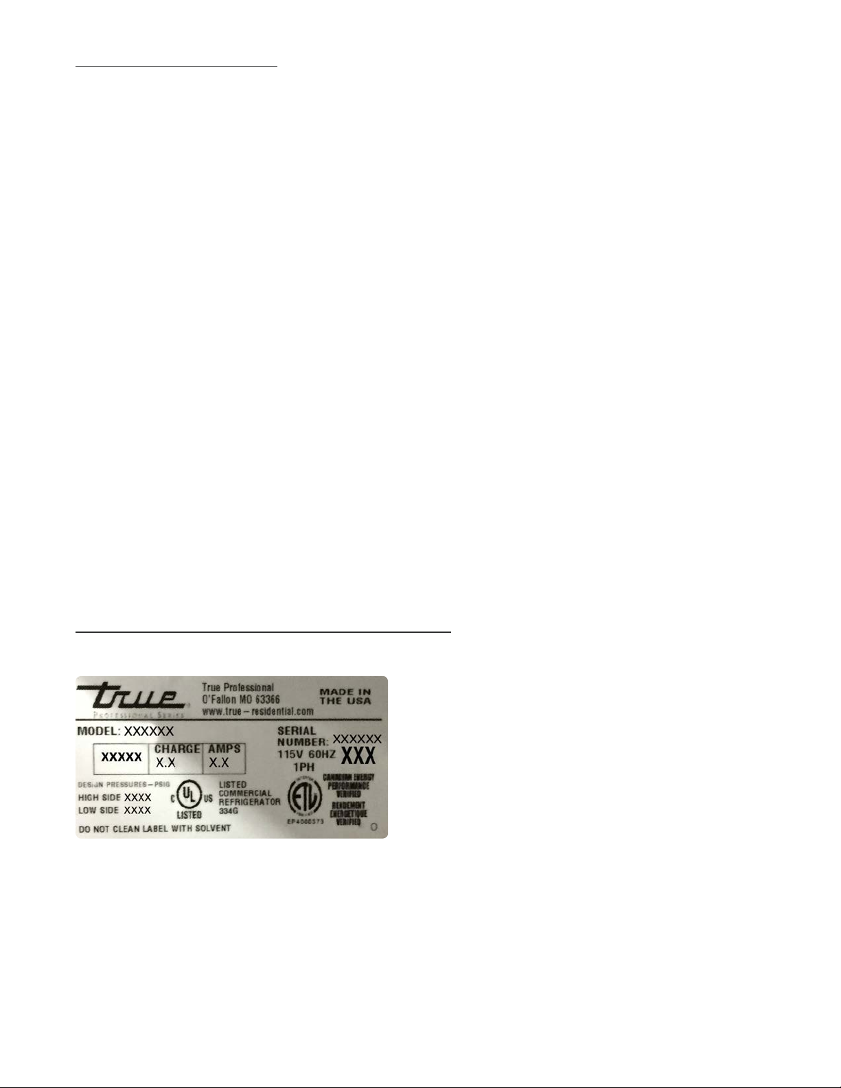
DATA TAG INFORMATION
Data tags are located on the interior upper left hand wall. The serial # is the method we track all pertinent
information for the unit.
15 & 24 INCH SERVICE MANUAL
3

DEPARTMENT CONTACT INFORMATION
TRUE-RESIDENTIAL.COM/SUPPORT
SERVICE DEPARTMENT – SUPPORTS AND TRAINS FIELD SERVICE PROVIDERS ON TRUE RESIDENTIAL EQUIPMENT
HELPS TROUBLESHOOT AND REPAIR SERVICE ISSUES IN THE FIELD ON TRUE RESIDENTIAL PRODUCTS
Residential Phone Number : 844-746-9423
Fax : 636-980-8510
Email : TrueResidentialService@truemfg.com
Mike Hurd
Dave Swift
Hours: Monday-Thursday 7:00AM-7:00PM CST
Friday 7:00AM-6:00PM
Saturday 8:00AM-12:00PM
WARRANTY DEPARTMENT – ANSWERS QUESTIONS REGARDING WARRANTY STATUS
PROCESSES WARRANTY CLAIMS & WARRANTY PARTS ORDERS FROM SERVICE PROVIDERS
Residential Phone Number : 844-849-6179
Fax : 636-980-8510
Email: TrueResidentialWarranty@truemfg.com
Stephanie Bouxsein
Diane Javaux
Submit Claims to: TrueResidentialWarranty@truemfg.com
Hours: Monday-Thursday 7:00AM-7:00PM CST
Friday 7:00AM-6:00PM
PARTS DEPARTMENT – OFFERS NON-WARRANTY PARTS SUPPORT
Residential Phone Number : 844-849-6226
Fax : 636-272-9471
Email: TrueResidentialParts@truemfg.com
Gabriela Childers
Abby Baker
Hours: Monday-Thursday 7:00AM-7:00PM CST
Friday 7:00AM-6:00PM
FOR COMMERCIAL PRODUCT INFORMATION, PLEASE CALL 800-325-6152
TRUE RESIDENTIAL
4
®

THANK YOU
FOR YOUR PURCHASE
ELECTRICAL SPECIFICATIONS
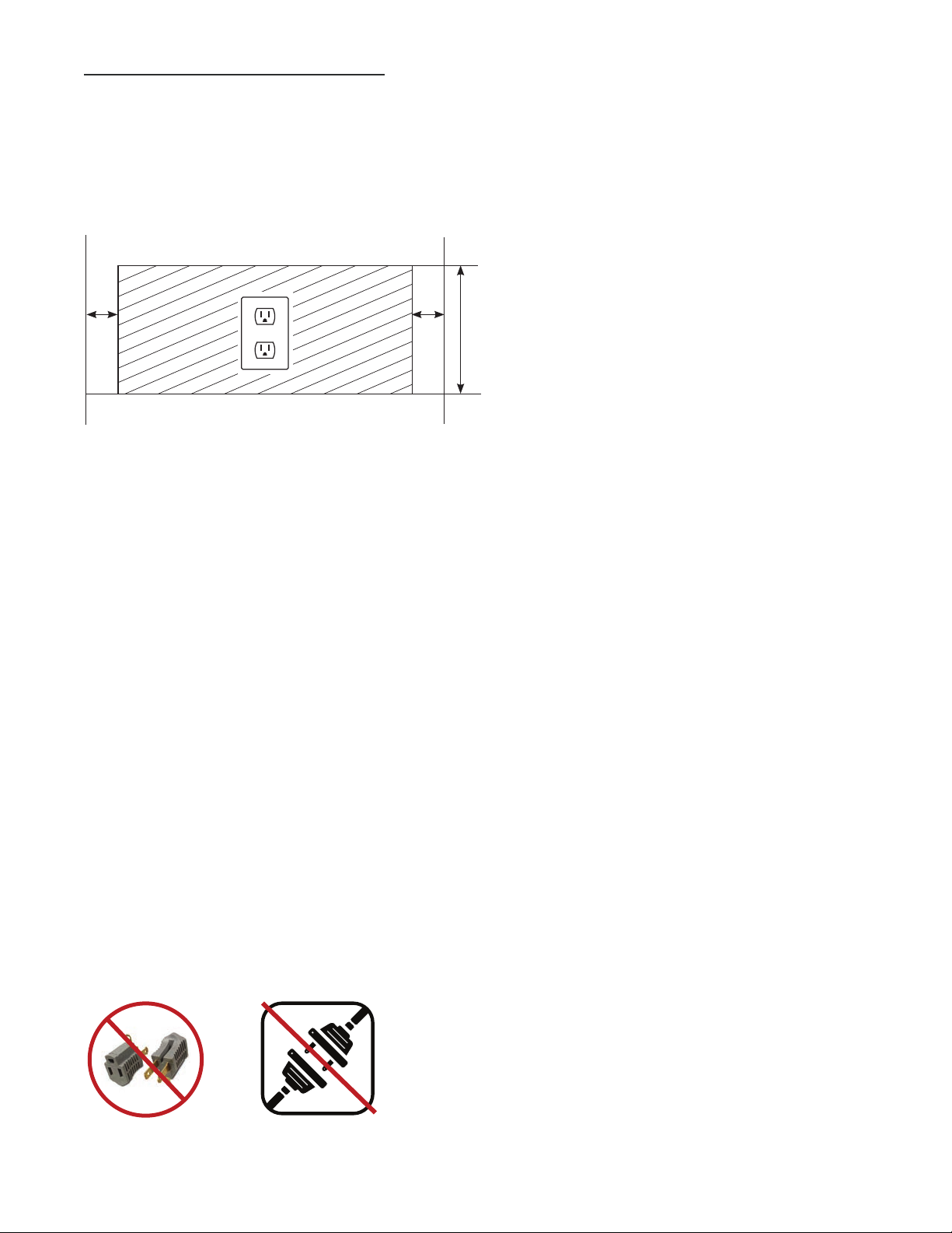
Do not, under any circumstances, cut or remove the third (ground) prong from the power cord. For personal
safety, this appliance must be properly grounded.
To minimize the depth of the cutout opening, the electrical outlet must be positioned as shown below. Outlet
must be flush with wall.
Rear wall of cut out
2” 2”
8”
Before your new unit is connected to a power supply, check the incoming voltage with a volt meter. If anything
less than 100% of the rated voltage for operation is noted, correct immediately.
The power cord of this appliance is equipped with a 3-prong (grounding) plug which mates with a standard
3-prong (grounding) wall outlet to minimize the possibility of electric shock hazard from this appliance. A 115V
AC, 60 Hz, 15 amp circuit breaker and electrical supply are required.
Each unit requires a dedicated circuit. Have the wall outlet and circuit checked by a qualified electrician to
make sure the outlet is properly grounded.
If the outlet is a standard 2-prong outlet, it is your personal responsibility and obligation to have it replaced with
the properly grounded 3 prong wall outlet.
Do not use an extension cord or two prong adaptor. Electrical ground is required on this appliance.
The unit should always be plugged into its own individual electrical circuit, which has a voltage rating that
matches the rating plate. This provides the best performance and also prevents overloading house wiring
circuits which could cause a fire hazard from overheated wires. Never unplug your refrigerator by pulling on
the power cord. Always grip plug firmly and pull straight out from the outlet.
Repair or replace immediately all power cords that have become frayed or otherwise damaged. Do not use
a cord that shows cracks or abrasion damage along its length or at either end. When moving the refrigerator
away from the wall, be careful not to roll over or damage the power cord.
WARNING: COMPRESSOR WARRANTIES ARE VOID IF
THE UNIT IS MORE THAN 7 FT. (2.1M) FROM PLUG-IN
CONNECTION OR IF AN EXTENSION CORD IS USED.
15 & 24 INCH SERVICE MANUAL
5
HOME ALARM SYSTEM - DUAL ZONE WINE CABINET ONLY
Dual Zone wine units are provided with three wires located behind the kick-plate that may be connected
to a home alarm system. These connections are for low voltage, low current circuits similar to those used
as signals for alarms on doors and windows. Refer to the specifications of your alarm system to determine
the type of circuit used.
The color codes for the different circuits are as follows:
• Normally closed contacts: White with black and violet
• Normally open contacts: White with blue and black
• Common: White with black
CAUTION: ANY UNUSED TERMINALS SHOULD BE FULLY INSULATED AND ALL WIRES
SHOULD BE SECURED AWAY FROM MOVING PARTS AND SHARP EDGES.
TRUE RESIDENTIAL
6
®
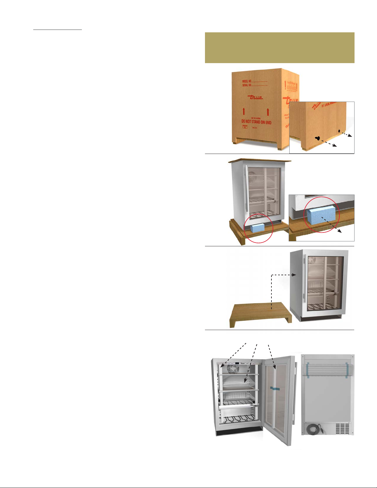
UNCRATING
Required Tools:
• Cutting utensil (utility knife)
• Claw hammer or tin snips
The following procedure is recommended for uncrating
the unit:
MOVE YOUR UNIT AS CLOSE TO THE FINAL LOCATION AS
POSSIBLE BEFORE REMOVING THE WOODEN SKID.
A. Remove nails securing cardboard box to the wooden
skid. Then discard any outer packaging (cardboard,
clear plastic).
B. IMPORTANT: Cut polyband and remove styrofoam
block from underside of the door.
INSPECT FOR CONCEALED DAMAGE.
IMMEDIATELY FILE A CLAIM WITH THE FREIGHT
CARRIER IF THERE IS DAMAGE.
A
B
C. Remove skid by carefully lifting the refrigerator off
and place skid aside.
D. Open the unit and remove any packing material.
Styrofoam, tape, and any other material used for
shipping purposes.
NOTE: KEYS FOR THE LOCK ARE PROVIDED WITH
THIS PACKET. STAINLESS STEEL UNITS
COME STANDARD WITH LOCKS. OVERLAY
PANEL READY UNITS WILL NOT BE EQUIPPED
WITH LOCKS.
NOTE: ANTI-TIP BRACKETS KIT AND DOOR STOP
ARE PACKED WITHIN THE TOE KICK WHICH
IS TAPED TO THE BACK OF THE UNIT. IF
THEY ARE NOT IN THE TOE KICK THEY WILL
BE PACKAGED INSIDE THE UNIT WITH THIS
M A NUAL.
C
D
PACKING MATERIAL
TOE KICK IS ATTACHED
TO BACK OF UNIT
FOR ANY MISSING OR BROKEN PARTS.
PLEASE CONTACT THE DEALER FROM
WHOM YOU PURCHASED THE UNIT.
15 & 24 INCH SERVICE MANUAL
7
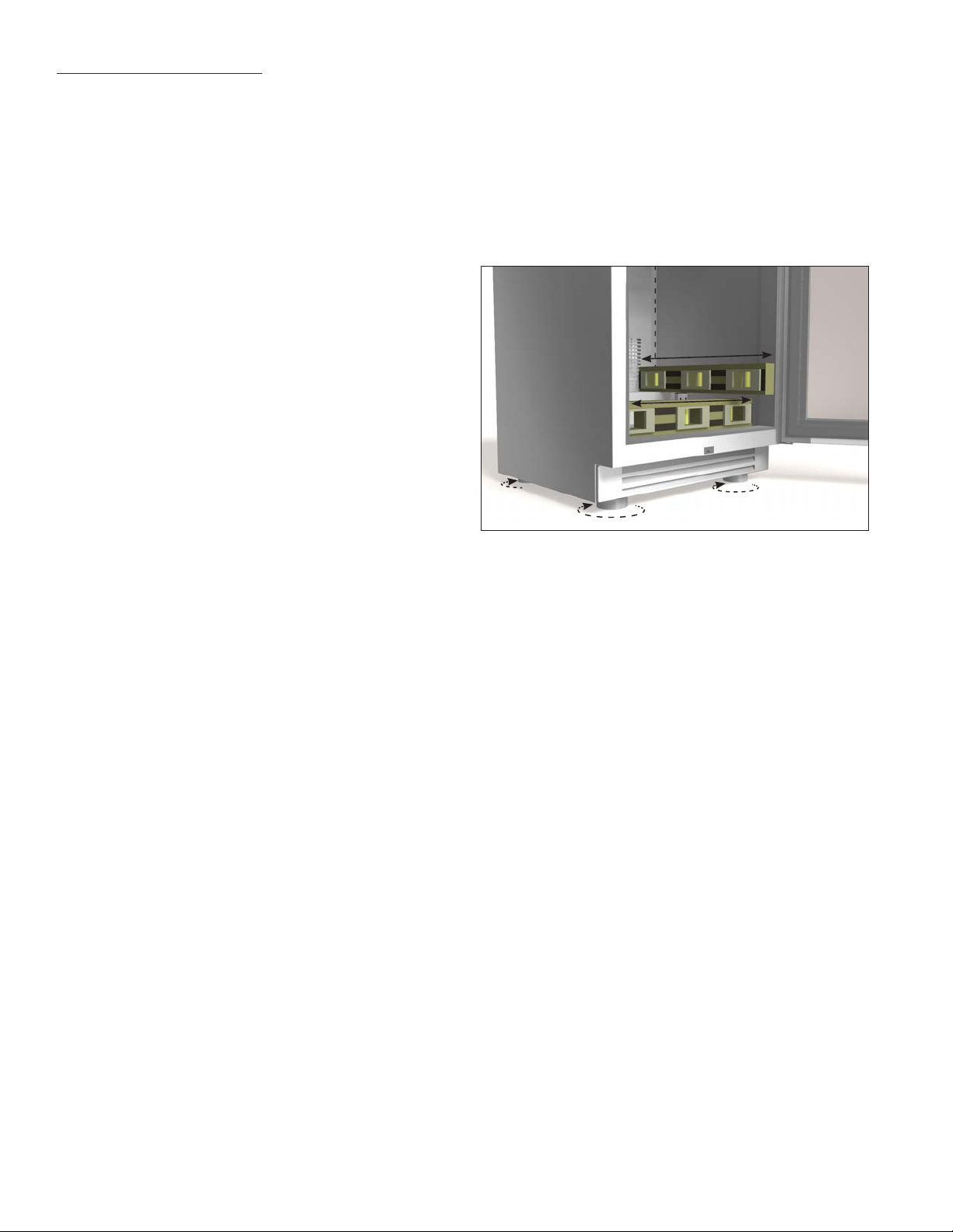
LEVELING THE UNIT
NOTE: PROPER LEVELING OF YOUR TRUE UNIT
IS CRITICAL TO OPERATING SUCCESS.
EFFECTIVE CONDENSATE REMOVAL AND
DOOR OPERATION WILL BE EFFECTED BY
LEVELING.
STEP 1 - Move the unit near the final location.
STEP 2 - Level your unit from the interior floor front
to back and side to side with a level. If the
refrigerator is not level adjust the stainless
steel leg levelers. The leg levelers can be
adjusted by turning CCW to reach the desired
leveling height as shown in the illustration
below.
STEP 3 - Free plug and cord from back of unit.
STEP 4 - The unit should be placed close enough to
the electrical supply so that extension cords
are never used. Plug unit directly into the
wall outlet.
STEP 5 - Once installed in final location, re verify level
and make final adjustments to the front legs.
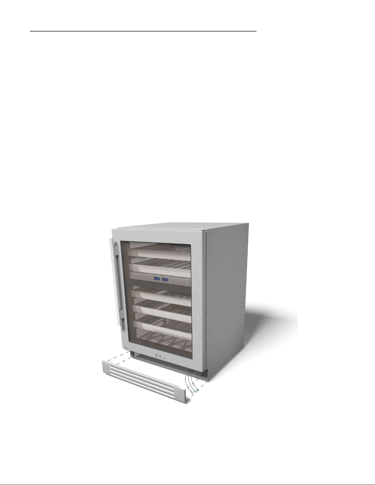
STEP 6 - Insert the toe kick on the clips (A) Version or
magnets (B) version.
TRUE RESIDENTIAL
8
®
ANTI-TIP BRACKET INSTALLATION
3.23.17 AC
TRUE RESIDENTIAL
®
211354
PRODUCT ADVISEMENT
KIT INCLUDES
• 2 Anti-tip brackets
• 4 Concrete screws (blue)
• 4 Wood screws (brass)
TOOLS REQUIRED
• Power drill
• Measuring Tape
IMPORTANT!
ALL FREE STANDING DRAWER (TUR-24D) OR STACKED UNITS MUST HAVE ANTI-TIP BRACKETS INSTALLED.
TIP-OVER HAZARD: A CHILD OR ADULT CAN TIP THE REFRIGERATOR. FAILURE TO FOLLOW THESE INSTRUCTIONS CAN RESULT
IN PROPERTY OR BODILY HARM.
BEFORE MOVING UNIT TAKE PRECAUTIONS TO PROTECT THE FLOOR.
Read all installation instructions first. Install the anti-tip brackets to hold both rear legs of the unit. Follow these steps
to secure the brackets to the floor before moving the unit into final operating position.
Contact a qualified floor installer for the best procedure of drilling mounting holes through your type of floor.
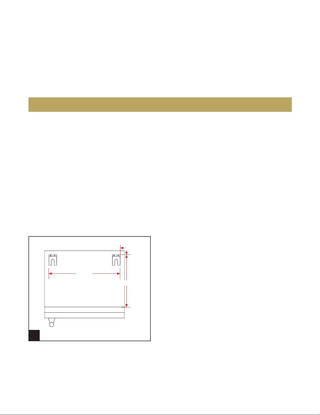
STEP 1
Back
3/16 "
22
Front
ANTI-TIP BRACKET (TOP VIEW)
1
18
27/ 32"
1/2"
Determine the location of the unit. The anti-tip
brackets will be installed 27/32" inset from the back
and sides of the unit. You can also measure 18 1/2"
from the front of the unit (not including the lower
louver grill). Using the bracket as a template, mark
the holes for drilling.
15 & 24 INCH SERVICE MANUAL
9
ANTI-TIP BRACKET INSTALLATION
3.23.17 AC
TRUE RESIDENTIAL
®
211354
PRODUCT ADVISEMENT
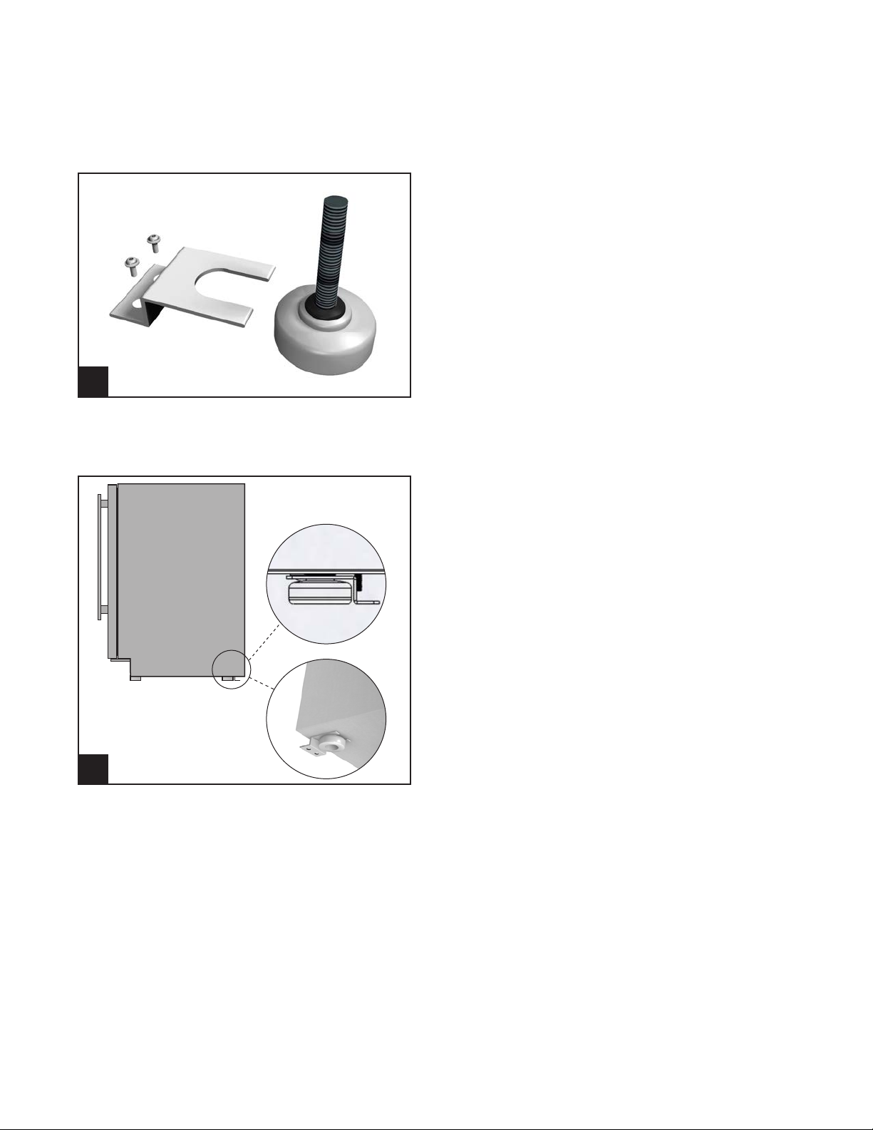
2
STEP 2
To mount the anti-tip bracket to wood floor, drill pilot
holes for each of the bracket holes. To mount the
anti-tip bracket to concrete or ceramic floor use a
masonry bit to drill pilot holes. Align anti-tip bracket
holes with the holes in the floor. Fasten anti-tip
bracket with screws provided using the brass colored
screw for wood, or blue colored masonry screw for
concrete.
STEP 3
Move unit into final position making sure rear leveling
legs slide into the anti-tip brackets.
3
TRUE RESIDENTIAL
10
®
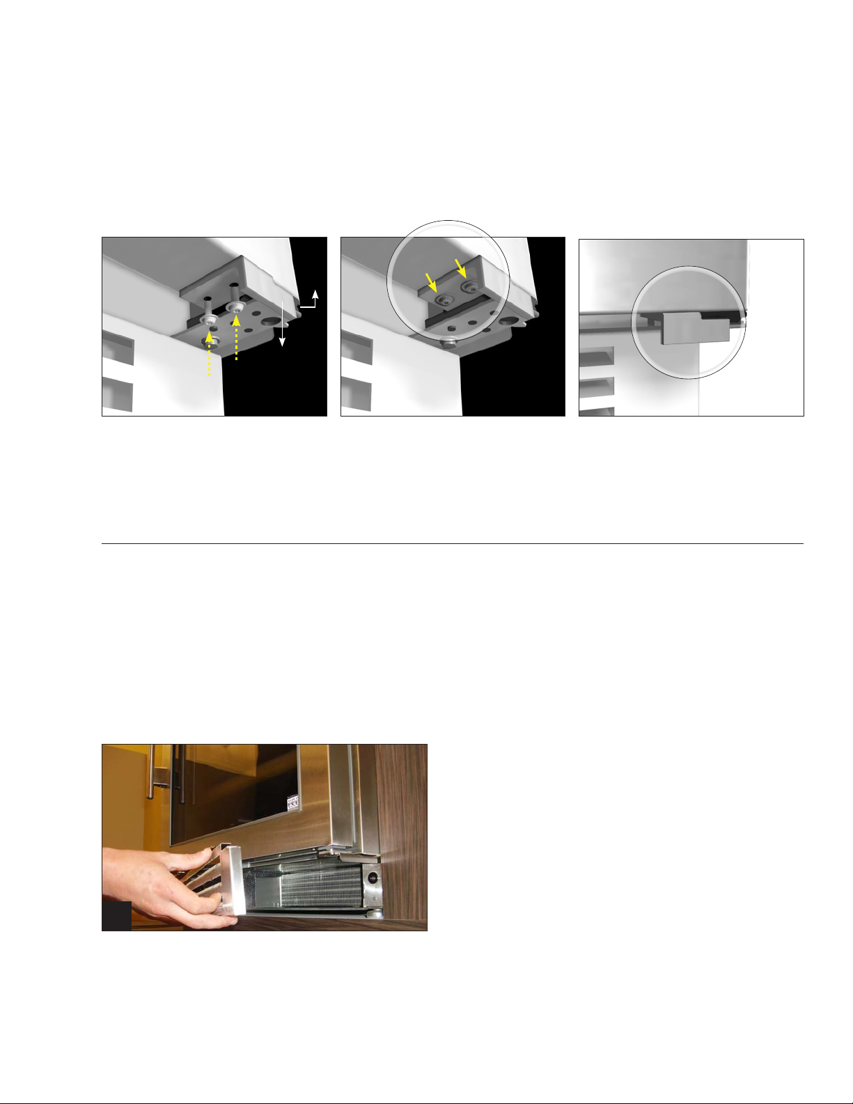
DOOR STOP INSTALLATION
INSTRUCTIONS FOR STAINLESS STEEL MODELS
ALL UNITS ARE PROVIDED WITH AN OPTIONAL DOOR STOP. WHEN INSTALLED, THE DOOR STOP WILL PREVENT
DAMAGE TO SURROUNDING CABINETS BY RESTRICTING THE DOOR FROM OPENING PAST APPROXIMATELY 120º
WITH A STANDARD HINGE OR 90º WITH AN 90º HINGE (OPTIONAL).
Hinge
Door stop
STEP 1
To install the door stop, use the 2 screws provided
and secure the bracket to the bottom of the door on
the same side as the hinge.
(OPTIONAL) 90° HINGE INSTALLATION
INSTRUCTIONS FOR STAINLESS STEEL MODELS
KIT INCLUDES
• 90º Hinge (left or right)
• Door stop bracket (left or right)
TOOLS REQUIRED
• 3/8" Socket wrench
• Phillips screwdriver
Door stop
installed
1
STEP 1
Remove toe kick.
15 & 24 INCH SERVICE MANUAL
11
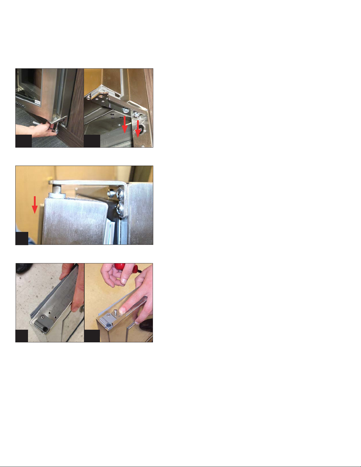
(OPTIONAL) 90° HINGE INSTALLATION
INSTRUCTIONS FOR STAINLESS STEEL MODELS
STEP 2
WARNING: Support the door while removing hinge.
Door is heavy and weight will cause it to drop if not
supported.
Remove 2 3/8" bolts to detach 120º door hinge
(standard).
2a
3
2b
STEP 3
Slowly remove door from unit by sliding down from
top hinge.
STEP 4
Install door stop using screws already installed.
Reinstall door by sliding up into top hinge.
4a
TRUE RESIDENTIAL
12
4b
®
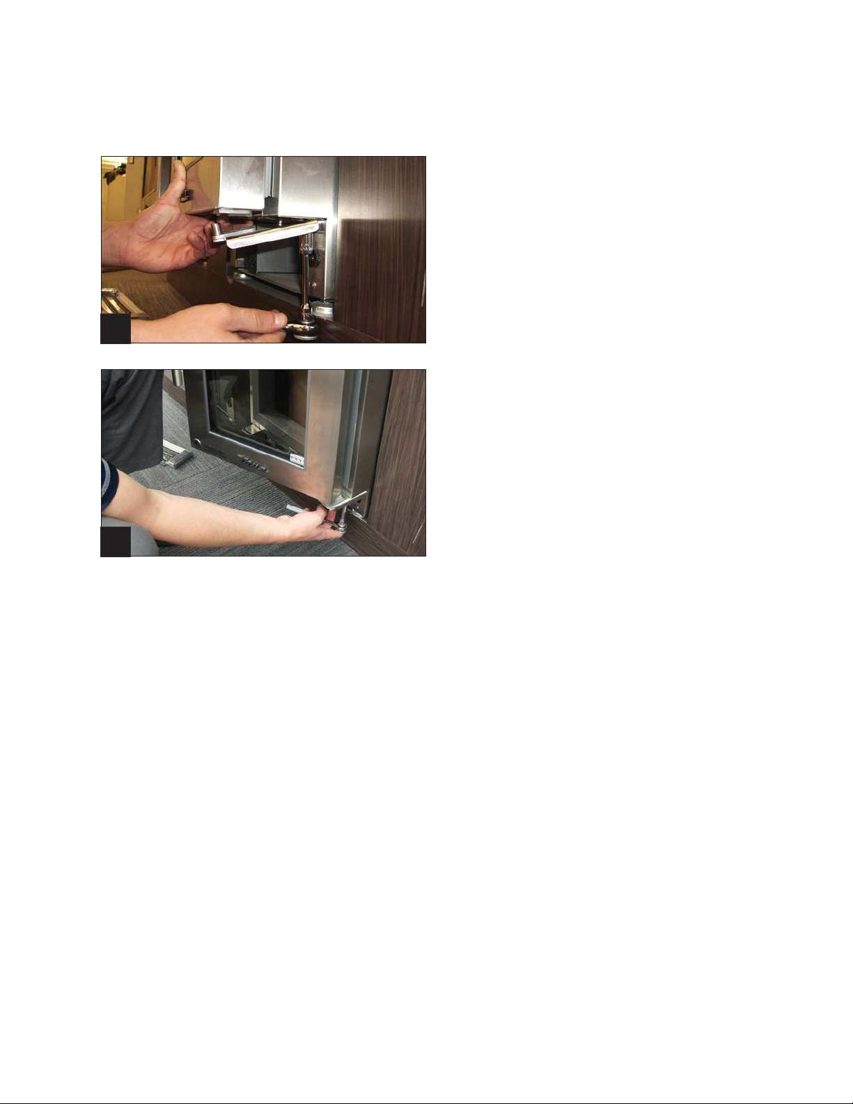
(OPTIONAL) 90° HINGE INSTALLATION
INSTRUCTIONS FOR STAINLESS STEEL MODELS
STEP 5
Install 90º hinge with the 2 3/8" bolts that you
removed. Note: Do not tighten screws all the way
until door adjustments have been made.
5
STEP 6
Align door with lock latch and light switch.
Tighten screws.
6
15 & 24 INCH SERVICE MANUAL
13
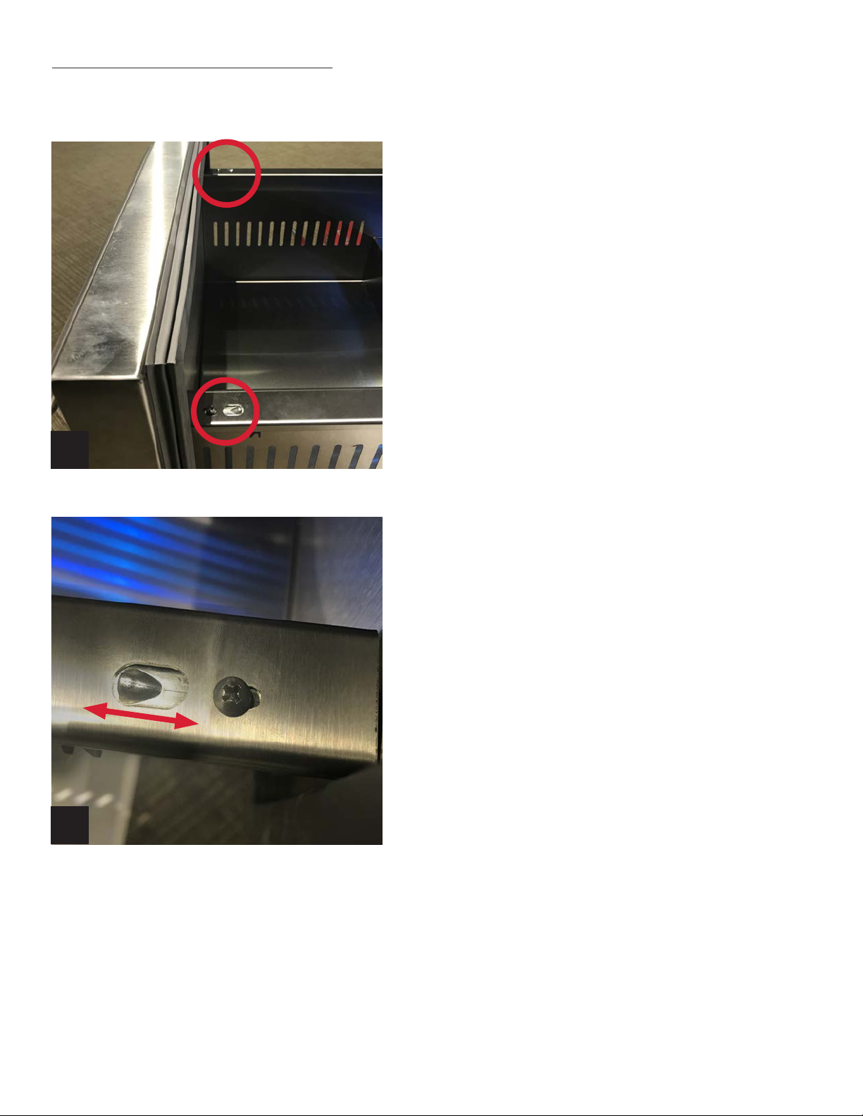
DRAWER DEPTH ADJUSTMENT
1
STEP 1
Loosen the left and right screws that mount the drawer
frame to the slide. See Image 1.
2
STEP 2
To bring the drawer out to the front of the unit, pull the
drawer out where the tab is seated towards the rear of the
unit. See Image 2.
STEP 3
Hold drawer position and tighten screws.
TRUE RESIDENTIAL
14
®

DRAWER FRONTS ON TRUE DRAWER REFRIGERATORS ADJUSTMENT
STEP 1 - Open the drawer that needs adjustment.
STEP 2 - Locate the two Phillips screws on each side of the drawer frame.
See figure 1
STEP 3 - Loosen the 2 screws on each side to get left to right movement
on the drawer front.
STEP 4 - Hold adjustment in place and re tighten the screws back down.
FIGURE 1.
DRAWER GLIDES ON TRUE DRAWER REFRIGERATORS ADJUSTMENT
STEP 1 - Remove screws (one on each side) on top of drawers at front.
STEP 2 - Remove drawers (lift out from the front)
STEP 3 - Loosen the two screws on the glide
STEP 4 - Use bottom screw to adjust glide
STEP 5 - Tighten side screws
STEP 6 - Replace drawer by aligning into tabs (in back)
STEP 7 - Reinsert screws in front
1
3
6
2
4
5
7
15 & 24 INCH SERVICE MANUAL
15
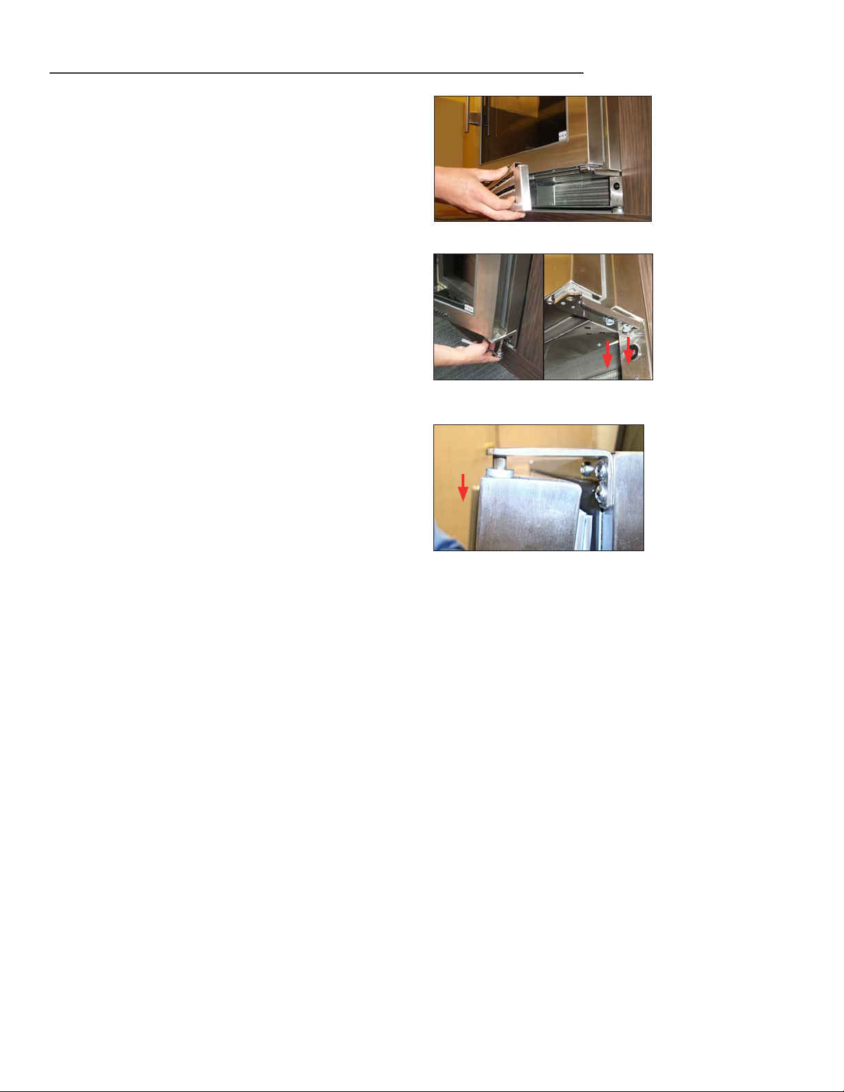
DOOR REMOVAL
STEP 1 - Remove the louver grill from the bottom of
the unit by simply pulling the grill toward the
front of the unit. See image 1.
STEP 2 - Support the door with your knee or a block to
prevent the door from falling to the ground
when the bolts are removed.
STEP 3 - Remove the two 3/8-inch bolts from the
bottom hinge using a ratchet and socket. See
image 2A and 2B.
STEP 4 - Pull the hinge out of the bottom of the door
and set it aside.
1
STEP 5 - Once these two bolts are removed, slightly
open the door, still supporting the weight
with your knee or a block, slowly allow the
door to drop down off the top hinge pin. See
image 3.
STEP 6 - Reinstall door by reversing sequence.
2A
3
2B
TRUE RESIDENTIAL
16
®
 Loading...