

Page 1

* Assembly Guide & Warranty Card Included
TC650 & TC900
TREADMILL
OWNER’S MANUAL
Revision 022620
Page 2

TC650/900 OWNERS MANUAL
IMPORTANT:
All products shown are prototype. Actual product delivered may vary.
Product specications, features & soware are subject to change without notice.
For the most up-to-date owner’s manual please visit www.truetness.com.
For documents in additional languages please visit www.truetness.com/resources/document-library/
IMPORTANTE:
Todos los productos mostrados son prototipos. La realidad el producto suministrado puede diferir.
Especicaciones de productos, características y soware están sujetas a cambios sin previo aviso.
Para la más actualizada de este manual del propietario, por favor visite www.truetness.com
Para los documentos en otros idiomas, por favor visite www.truetness.com/resources/document-library/
IMPORTANT: Tous les produits présentés sont prototype. Le produit réel livré peut varier. Spécications du
produit, caractéristiques et logiciels sont sujettes à modication sans préavis. Pour la plus à jour le manuel du
propriétaire s'il vous plaît visitez www.truetness.com. Pour documents dans des langues supplémentaires,
veuillez www.truetness.com/resources/document-library/ de visite
重要提示: 显示所有产品的原型。实际交付的产品可能有所不同产品规格,功能和软件如有更改,恕不另
行通知迄今为止对于大多数的使用说明书,请访问www.truetness.com 对于其他语言的文档,请访问
www.truetness.com/resources/document-library/
ھام:
جمیع المنتجات المعروضة ھي النموذج. قد تختلف المنتج الفعلي تسلیمھا.
مواصفات المنتج، والمیزات والبرامج قابلة للتغییر دون إشعار.
لمعظم ما یصل حتى الآن دلیل المالك یرجى زیارة www.truetness.com.
للمستندات في لغات إضافیة، یرجى زیارة www.truetness.com/resources/document-library/
WICHTIG: Alle hier gezeigten Produkte sind Prototypen. Das tatsächliche Produkt ausgeliefert wird, kann
variieren. Produkt-Spezikationen, Funktionen und Soware können sich ohne vorherige Ankündigung
ändern. In den meisten Fällen bis zu Bedienungsanleitung Bisher besuchen Sie bitte www.truetness.com. Für
Dokumente in weiteren Sprachen nden Sie unter www.truetness.com/resources/document-library/
BELANGRIJK: Alle getoonde producten zijn prototype. Daadwerkelijke product geleverd kan verschillen.
Product specicaties, eigenschappen & soware zijn onderhevig aan verandering zonder kennisgeving. Voor
de meest actuele handleiding van de eigenaar kunt u terecht www.truetness.com. Voor documenten in andere
talen kunt u terecht op www.truetness.com/resources/document-library/
: . , .
,
.
, www.truetness.com
. , , www.truetness.com/resources/document-library/
Truetness.com / 800.426.6570 / 636.272.7100
2 of 61
Page 3

TC650/900 OWNERS MANUAL
A MESSAGE TO OUR CUSTOMERS
Frank Trulaske began TRUE Fitness® over thirty-ve year ago with the simple philosophy of delivering superior
tness products, service, and support. Today, TRUE is the global leader in premium tness equipment for the
commercial and residential markets. Our goal is to be the leader in technology, innovation, performance, safety
and style. TRUE has received many awards for its product over the years and remains the benchmark for the
industry. Fitness facilities and consumers invest in TRUE products for their durable commercial platforms used
in all its products, both commercial and residential alike.
e proud manufacturing tradition of quality and the culture of innovation at TRUE have given rise to a full line
of extraordinary cardio and strength equipment. As a result, people all over the world are beneting from the
TRUE experience. Innovation across the full product line has made TRUE successful and is a trademark of the
TRUE heritage. TRUE’s patented Heart Rate Control technology is just one of the remarkable ways we deliver
simple and superior performance every user can enjoy, and most importantly, use to achieve personal health and
tness goals.
At the heart of our success is the relentless and systematic life testing of both our products and their components.
We have dedicated employees who understand our philosophy is to deliver the best products in the world.
Our goal is to deliver the world’s best premium equipment for our customers’ health and tness solutions.
Truetness.com / 800.426.6570 / 636.272.7100 3 of 61
Page 4

TC650/900 OWNERS MANUAL
TABLE OF CONTENTS:
Chapter 1: Safety Instructions
Safety Instructions ..................................................................................................................................................................5
Space Requirements ...............................................................................................................................................................8
Grounding Instructions .........................................................................................................................................................9
Power Requirements ............................................................................................................................................................10
Warning Decals.....................................................................................................................................................................11
Compliances ..........................................................................................................................................................................11
Chapter 2: Assembly Instructions
Pre Assembly Checklist .......................................................................................................................................................13
Assembly Steps ......................................................................................................................................................................15
Chapter 3: Product Overview
Product Overview ................................................................................................................................................................37
Chapter 4: Care & Maintenance
Care & Maintenance ............................................................................................................................................................39
Cleaning the Equipment ......................................................................................................................................................39
Running Belt Alignment .....................................................................................................................................................40
Tensioning the Running Belt ..............................................................................................................................................41
Belt Lubrication ....................................................................................................................................................................41
Leveling the Equipment .......................................................................................................................................................42
Other Scheduled Preventive Maintenance ........................................................................................................................42
Long Term Storage ...............................................................................................................................................................42
Chapter 5: Customer Service
Contacting Service ...............................................................................................................................................................43
Contacting Sales ...................................................................................................................................................................43
Reporting Freight or Parts Damage ...................................................................................................................................44
Chapter 6: Additional Information
Troubleshooting Guide ........................................................................................................................................................45
Wiring Diagram....................................................................................................................................................................52
Chapter 7: Warranty Information
TC650 Warranty ...................................................................................................................................................................56
TC900 Warranty ...................................................................................................................................................................59
Truetness.com / 800.426.6570 / 636.272.7100
Page 5

CHAPTER 1: SAFETY INSTRUCTIONS
IMPORTANT SAFETY INSTRUCTIONS
SAVE THESE SAFETY INSTRUCTIONS
is equipment is intended for a commercial or institutional setting. is owner’s manual should be accessible to all
personal trainers, faculty, and members.
WARNING: ALL EXERCISERS MUST READ ALL INSTRUCTIONS BEFORE USING THE
EQUIPMENT.
WARNING: Heart rate monitoring systems may be inaccurate for some individuals. Over-exercising
may result in serious injury or death. If you feel faint, stop exercising immediately.
WARNING: Equipment should be immediately taken out of use if it fails to work properly or when a
warning is presented electronically.
TRUE STRONGLY recommends seeing a physician for a complete medical exam before undertaking an exercise program,
particularly if the user has a family history of high blood pressure or heart disease, is over the age of 45, smokes, has high
cholesterol, is obese or has not exercised regularly in the past year. Additionally, TRUE recommends consulting a tness
professional on the correct use of this product. If at any time while exercising the user experiences faintness, dizziness,
pain or shortness of breath, he or she must stop immediately.
WARNING: To reduce the risk of electrical shock, always unplug this TRUE product before cleaning
or attempting any maintenance activity. Do not handle the plug with wet hands.
WARNING: To reduce the risk of burns, re, electric shock, or injury, it is imperative to connect
each product to a properly grounded 110V electrical outlet. A risk of electrical shock may result from improper
connection of the equipment’s grounding conductor. Check with a qualied electrician if you are unsure about
proper ground techniques. Do not modify the plug provided wiht this product. If it will not t an electrical outlet,
have a proper outlet installed by a qualied electrician. Your TRUE Fitness product must be properly grounded
to reduce risk of shock if the equipment malfunctions. Your equipment is equipped with an electrical cord, which
includes an equipment grounding conductor and a grounding plug. e plug must be inserted into an outlet that
has been properly installed and grounded in accordance with all local codes and ordinances. A temporary adapter
cannot be used to connect this plug to a two-pole receptacle in North America. If a properly grounded 15 amp
outlet is not available, a qualied electrician must install one.
WARNING: Do not move the equipment by liing the console. Do not use the console as a handlebar
during a workout.
WARNING: is product contains chemicals known to the state of California to cause cancer and birth
defects or other reproductive harm.
WARNING: Keep equipment stable on at ground.
Truetness.com / 800.426.6570 / 636.272.7100 5 of 61
Page 6

CHAPTER 1: SAFETY INSTRUCTIONS
WARNING: Replace warning labels that may be worn, damaged, or missing.
WARNING: Replace any non-working or damaged components, remove the unit from service until repair
is performed.
WARNING: To reduce the risk of burns, re, and electric shock or injury to persons, follow these
instructions:
• is appliance should never be le unattended when plugged in.
• Do not use any type of extension cord with this product.
• Unplug it from the outlet when not in use and before any servicing.
• Do not operate the equipment while being covered with a blanket, plastic, or anything that insulates or stops airow.
WARNING: Risk of personal injury-crushing hazard when equipment is in operation - Keep feet, hands,
and ngers away from moving parts.
CAUTION:
• Do not use typing or web surng features at excessive speeds. Always stabilize yourself by holding a stationary handle
when using typing or web surng features. (Varies by console option)
• Health related injuries may result from incorrect or excessive use of exercise equipment.
• Do not use the contact heart rate grips as a handlebar during a workout.
• Any changes or modications to this equipment could void the product warranty.
• To disconnect, turn power OFF at the ON/OFF switch if applicable, then remove plug from electrical outlet.
• Never operate a TRUE product if it has a damaged power cord or electrical plug, or if it has been dropped, damaged,
or even partially immersed in water. Contact TRUE Customer Service for a replacement.
• Use a TRUE AC power cord or AC/DC adapter only.
• *Note the plug conguration for the power adapter may vary by country.
• Position this product so the power cord plug is accessible to the user.
• Keep the power cord away from heated surfaces. Do not pull the equipment by the power cord or use the cord as a
handle. Do not run the power cord along the side or under the treadmill.
• If the electrical supply cord is damaged it must be replaced by the manufacturer, an authorized service agent, or a
similarly qualied person to avoid a hazard.
• Do not use this product in areas where aerosol spray products are being used or where oxygen is being administered.
Such substances create the danger of combustion and explosion.
• Always follow the console instructions for proper operation.
• Close supervision is necessary when used near children under the age of 15, or disabled persons.
• Do not use this product outdoors, near water, while wet, or in areas of high humidity including extreme temperature
changes.
• Never operate a TRUE product with the air openings blocked. Keep air openings free of lint, hair or any obstructing
material.
• Never insert objects into any openings in this product. If an object should drop inside, turn o the power, unplug the
power cord from the outlet and carefully retrieve it. If the item cannot be reached, contact TRUE Customer Service.
• Never place liquids of any type directly on the unit except in the accessory tray or bottle holders. Containers with lids
are recommended.
• Wear shoes with rubber or high traction soles. Do not use shoes with heels, leather soles, cleats or spikes. Make sure
no stones are embedded in the soles. Do not use this product in bare feet. Keep all loose clothing, shoelaces and towels
away from moving parts.
• Do not reach into or underneath the unit, or tip it on its side during operation.
• Use correct ergonomic positioning while running on treadmill.
• Do not allow animals on or near the equipment while in operation.
Truetness.com / 800.426.6570 / 636.272.7100
6 of 61
Page 7
CHAPTER 1: SAFETY INSTRUCTIONS
CAUTION:
• Use the side handrails whenever additional stability is required. In case of emergency, such as tripping, the side
handrails should be grabbed and the user should place his/her feet on the side platforms. e front handlebars should
be used to grasp the heart rate sensors or to rest the hand on while operating the activity zone keys, but not for
stability, emergency, or continuous use.
• Do not exceed TC650 maximum user weight of 500lbs (226 kg).
• Do not exceed TC900 maximum user weight of 500lbs (226 kg).
• Do not use if you have a cold or fever.
• When using this exercise machine, basic precautions should always be followed.
• Use this equipment only for its intended use as described in this manual.
• Do not use attachments not recommended by the manufacturer.
• Allow only trained personnel to service this equipment.
• Avoid the possibility of bystanders being struck or caught between moving parts by making sure that they are out of
reach of the equipment while it is in motion.
• is appliance can be used by children aged from 8 years and above and persons with reduced physical, sensory or
mental capabilities or lack of experience and knowledge if they have been given supervision or instruction concerning
use of the appliance in a safe way and understand the hazards involved.
• Children shall not play with the appliance.
• Cleaning and user maintenance shall not be made by children without supervision.
• Allow only one person at a time on the equipment while it’s operating.
• It is the sole responsibility of the owner/operator to ensure regular and scheduled maintenance is performed.
• To avoid injury stand on the side rails before starting the treadmill.
• Avoid exiting treadmill while leaving the tread belt in motion.
• Never walk or jog backwards on the treadmill.
• When mounting the treadmill, ensure the treadmill belt is not running and then proceed with one step at a time to
maintain balance using the handrails as needed.
• While the treadmill is in use, proceed at a speed that the user can safely maintain with the ability to immediately
engage the safety key to stop the treadmill belt if necessary.
CAUTION:
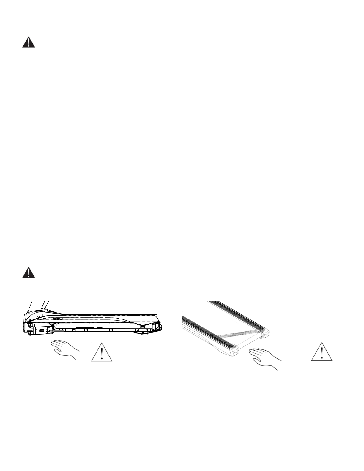
• To avoid serious injury, do not touch the incline rack while the treadmill is in use.
• To avoid serious injury, do not touch the belt while the treadmill is in use.
NOISE EMMISIONS:
Noise emission under load is higher than without load.
Note: A-weighted emission sound pressure level at the trainer’s ear: 67dBA
Noise emission under load is 60dB. (According to TUV testing result.) Noise emission is 60 dB (A), which is at speed
12km/h and no load.
Truetness.com / 800.426.6570 / 636.272.7100 7 of 61
Page 8
CHAPTER 1: SAFETY INSTRUCTIONS
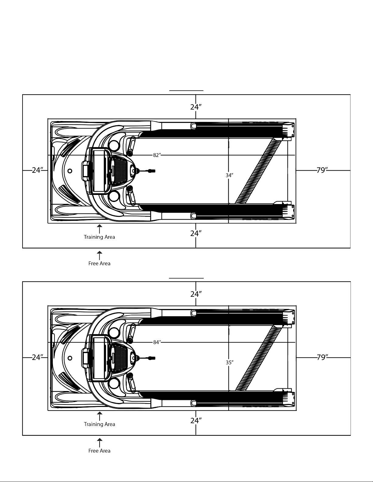
SPACE REQUIREMENTS:
TRUE’s recommendation is to leave a minimum of 24” (0.6m) on each side of the treadmill and a 79” (2 m) safety zone at
the rear of the treadmill.
TC650:
TC900:
Truetness.com / 800.426.6570 / 636.272.7100
8 of 61
Page 9
CHAPTER 1: SAFETY INSTRUCTIONS
GROUNDING INSTRUCTIONS:
is product must be grounded, if it should malfunction or breakdown, grounding provides a path of least resistance for
electric current to reduce the risk of electric shock. is product is equipped with a cord having an equipment-grounding
conductor and a grounding plug. e plug must be plugged into an appropriate outlet that is properly installed and
grounded in accordance with all local codes and ordinances.
DANGER:
• Improper connection of the equipment-grounding conductor can result in a risk of electric shock.
• Check with a qualied electrician or serviceman if you are in doubt as to whether the product is properly
grounded. Do not modify the plug provided with the product. If it will not t the outlet, have a proper outlet
installed by a qualied electrician.
• Do not remove the motor cover or you may risk injury due to electric shock.
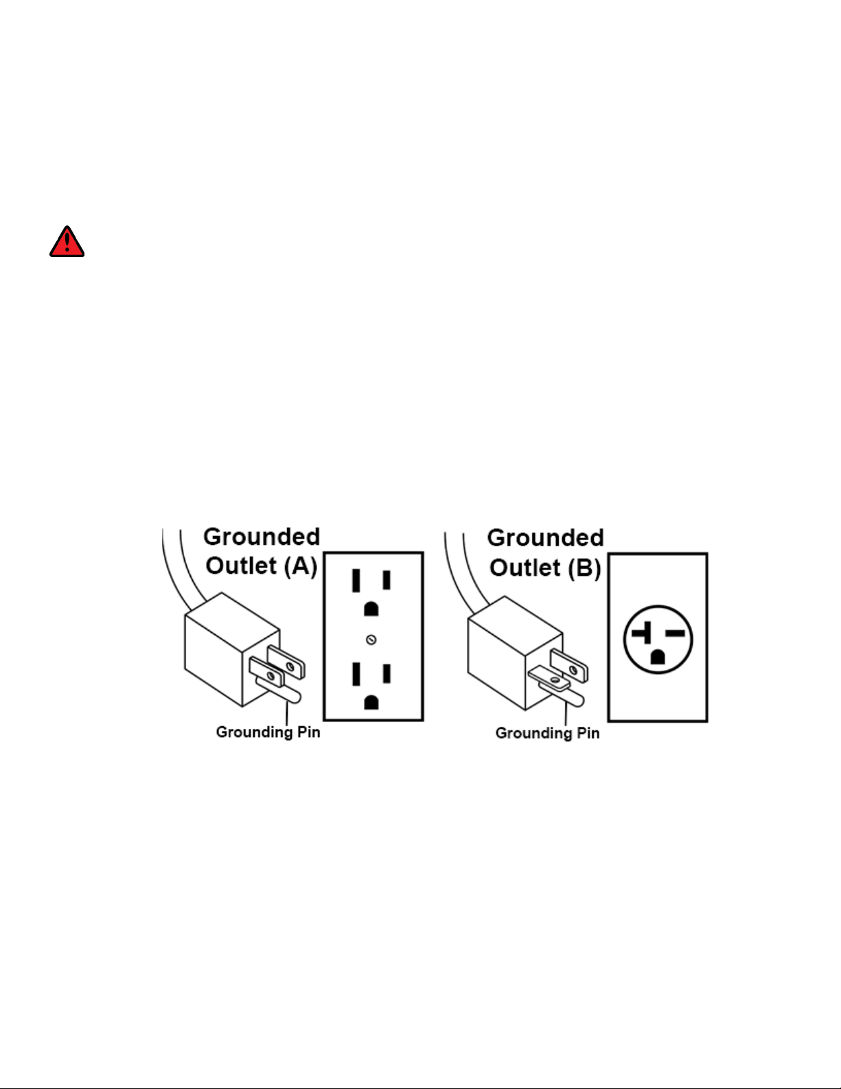
• 120-Volt: is model is for use on a nominal 120-V circuit and has a grounding plug that looks like the plug
illustrated in gure A. Make sure the product is connected to an outlet having the same conguration as the
plug. No adaptor should be used with this product.
• 230-Volt: is model is for use on a circuit having a nominal rating more than 120-V and is factory-equipped
with a specic electric cord and has a grounding plug that looks like the plug illustrated in gure B. Make sure
that the product is connected to an outlet having the same conguration as the plug in Figure B. No adapter
should be used with this product. If the product must be reconnected for use on a dierent type of electric
circuit, the reconnection should be made by qualied service personnel.
Truetness.com / 800.426.6570 / 636.272.7100 9 of 61
Page 10
CHAPTER 1: SAFETY INSTRUCTIONS
Truetness.com / 800.426.6570 / 636.272.7100
10 of 61
Page 11
CHAPTER 1: SAFETY INSTRUCTIONS
SAMPLE
SAMPLE
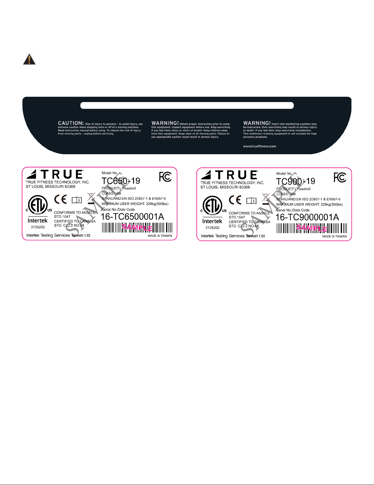
WARNING DECALS:
WARNING: Replace warning labels that may be worn, damaged, or missing.
To replace any worn or missing decals contact TRUE FITNESS by visiting www.truetness.com or contact customer
service at 800-883-8783.
COMPLIANCES:
is equipment complies with all applicable codes and regulations. For a complete list of compliances, please visit
www.truetness.com.
Truetness.com / 800.426.6570 / 636.272.7100 11 of 61
Page 12

CHAPTER 2: ASSEMBLY GUIDE
IMPORTANT SAFETY INSTRUCTIONS
• Read and understand all instructions and warnings prior to use.
• Obtain a medical exam before beginning any exercise program. If at any time during exercise
youfeel faint, dizzy, or experience pain, stop and consult your physician.
• Obtain proper instruction prior to use.
• is unit is intended for commercial use only.
• Inspect the unit for incorrect, worn, or loose components and do not use until corrected,
replaced,or tightened prior to use.
• Do not wear loose or dangling clothing while using the unit.
• Care should be used when mounting or dismounting the unit.
• Read, understand, and test the emergency stop procedures before use.
• Disconnect all power before servicing the unit.
• Do not exceed maximum user weight of 400 lbs.
• Keep the top side of the moving surface clean and dry.
• Keep children and animals away.
• Use caution when moving and assembling unit.
• All exercise equipment is potentially hazardous. If attention is not paid to the conditions
ofequipment usage, death, or serious injury could occur.
• Save these instructions.
Basic Guidelines for Setting Up the Equipment:
Aer removing the equipment from the packaging, place the equipment on a clean, level surface. Make sure the electrical
cord easily reaches a grounded three-pronged outlet.
Important Electrical Requirements – 120V:
Your TRUE equipment requires a dedicated 120 volt, alternating current (AC), 20 amp grounded outlet circuit. is means
nothing else can be plugged into the same circuit. Most power circuits are rated for this 120V AC 20 amp requirement, but
you must ensure the equipment does not share the circuit with anything else.
Important Electrical Requirements – 220V:
Your TRUE equipment requires a dedicated 230 volt, alternating current (AC), 15 amp grounded outlet circuit. is means
nothing else can be plugged into the same circuit. Most power circuits are rated for this 230V AC 15 amp requirement, but
you must ensure the equipment does not share the circuit with anything else.
DANGER: Do not use an extension cord or ungrounded outlet:
e ground helps prevent electrical damage to your equipment and enhances your safety by helping to prevent shock.
Check with a qualied electrician or serviceman if you are in doubt as to whether the equipment is properly grounded.
Do not modify the plug provided with the unit if it will not t the outlet. Have a proper outlet installed by a qualied
electrician.
Truetness.com / 800.426.6570 / 636.272.7100
12 of 61
Page 13
CHAPTER 2: ASSEMBLY GUIDE
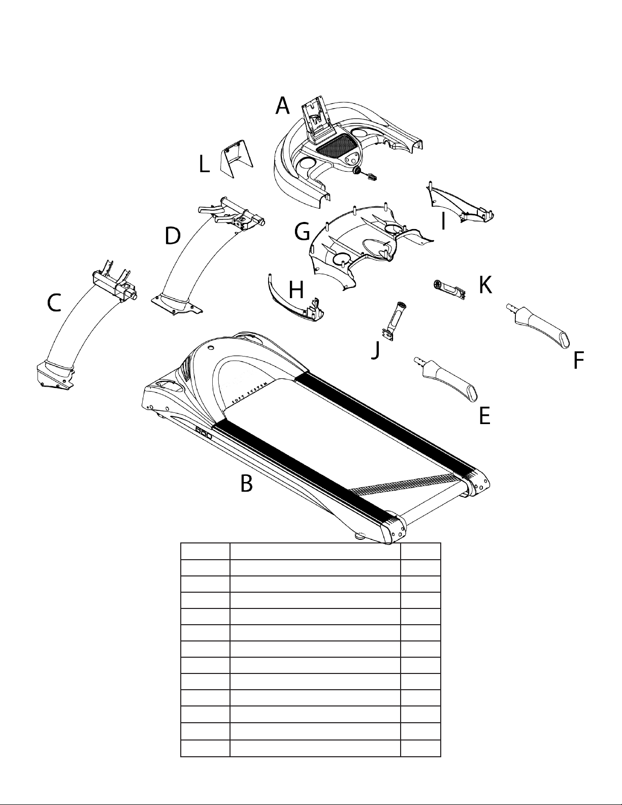
PRE-ASSEMBLY CHECKLIST:
ITEM DESCRIPTION Qty.
A Console Rack 1
B Frame 1
C Pedestal - Le 1
D Pedestal - Right 1
E Handrail - Le 1
F Handrail - Right 1
G Lower Console Rack Cover 1
H Lower Shoulder Cover-Le 1
I Lower Shoulder Cover-Right 1
J
K
L
Hand Grip Assembly - Le
Hand Grip Assembly - Right
Rear Console Cover
1
1
1
Truetness.com / 800.426.6570 / 636.272.7100 13 of 61
Page 14
CHAPTER 2: ASSEMBLY GUIDE
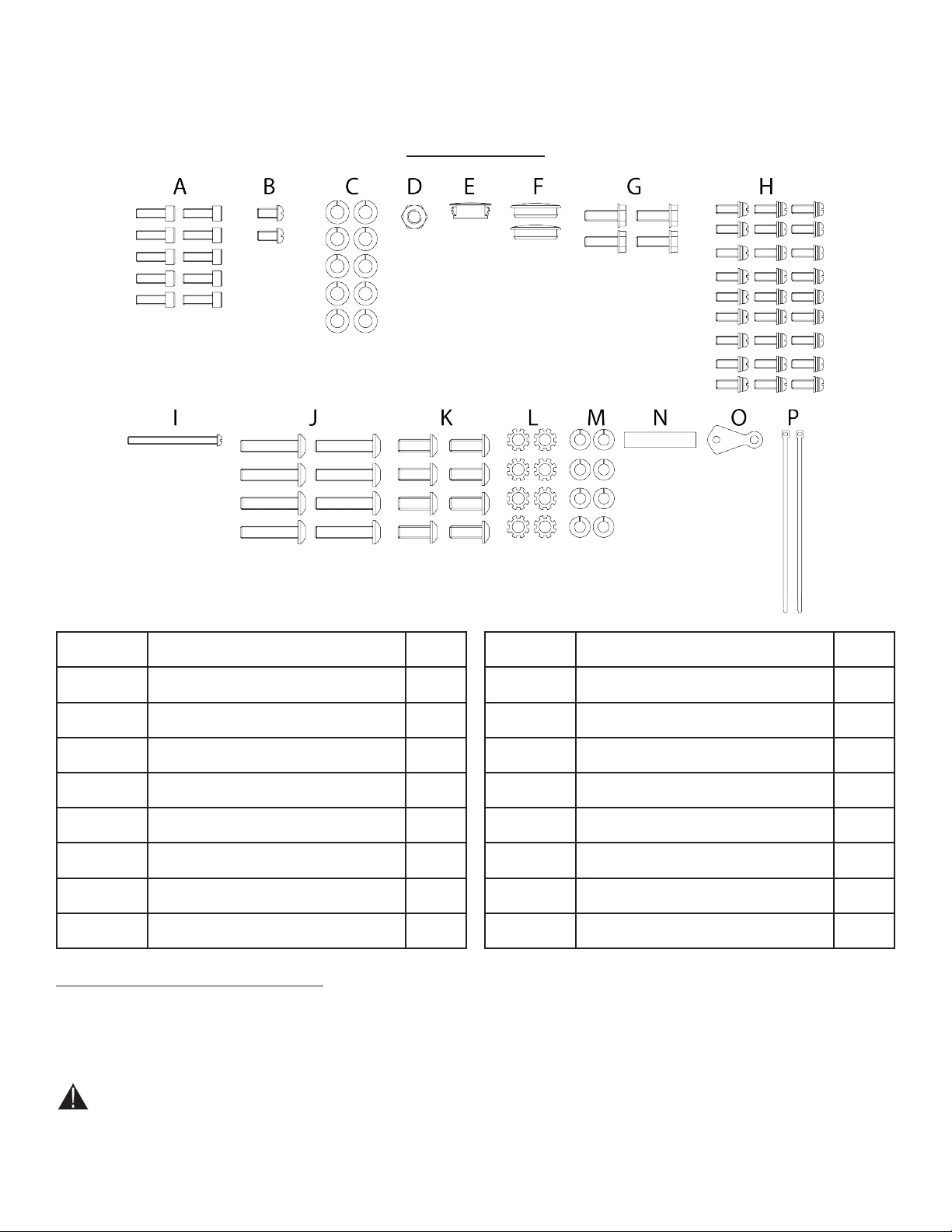
PRE-ASSEMBLY CHECK LIST:
TC650/900
Item Description Qty
A Bolt M8 x P1.25 x 25 10
B Screw M5 x P0.8 x 10 2
C Lock Washer M8 10
D Lock Nut M8 x P1.25 1
E Cap-Motor Cover Screw 1
F Hole Plug-Motor Cover 2
G Bolt 1/4”-20 x 3/4” 4
H Screw M4 x P0.7x12 27
Tools Required (not included):
• Open End Wrenches: 15/16”, 7/8”, and 1/2”
• Hex Keys: 5/32”, 3/16”, 4mm, and 8mm
• Screwdrivers: #2 Phillips with 4” long tip, #2 Phillips
with 8” long tip, 5/16” slotted approximately 6” long
Item Description Qty
I Bolt M5 x P0.8 x 60 1
J Bolt 5/16”-24 x 1-1/2” 8
K Bolt 1/4”-20 x 5/8” 8
L External Tooth Star Washer M8 8
M Lock Washer 1/4” 8
N Spacer 1
O Retainer-Power Cord 1
P Wire Tie 2
• 7/16” 6-point socket, short extension, and ratchet
• Long-nose pliers, small (optional)
• Wire cutters, small (optional)
CAUTION:
• Use caution when assembling treadmill. Unpacking and assembling of this treadmill is a two person task.
• Remove all treadmill components from packaging.
Truetness.com / 800.426.6570 / 636.272.7100
14 of 61
Page 15
CHAPTER 2: ASSEMBLY GUIDE
TREADMILL ASSEMBLY STEPS:
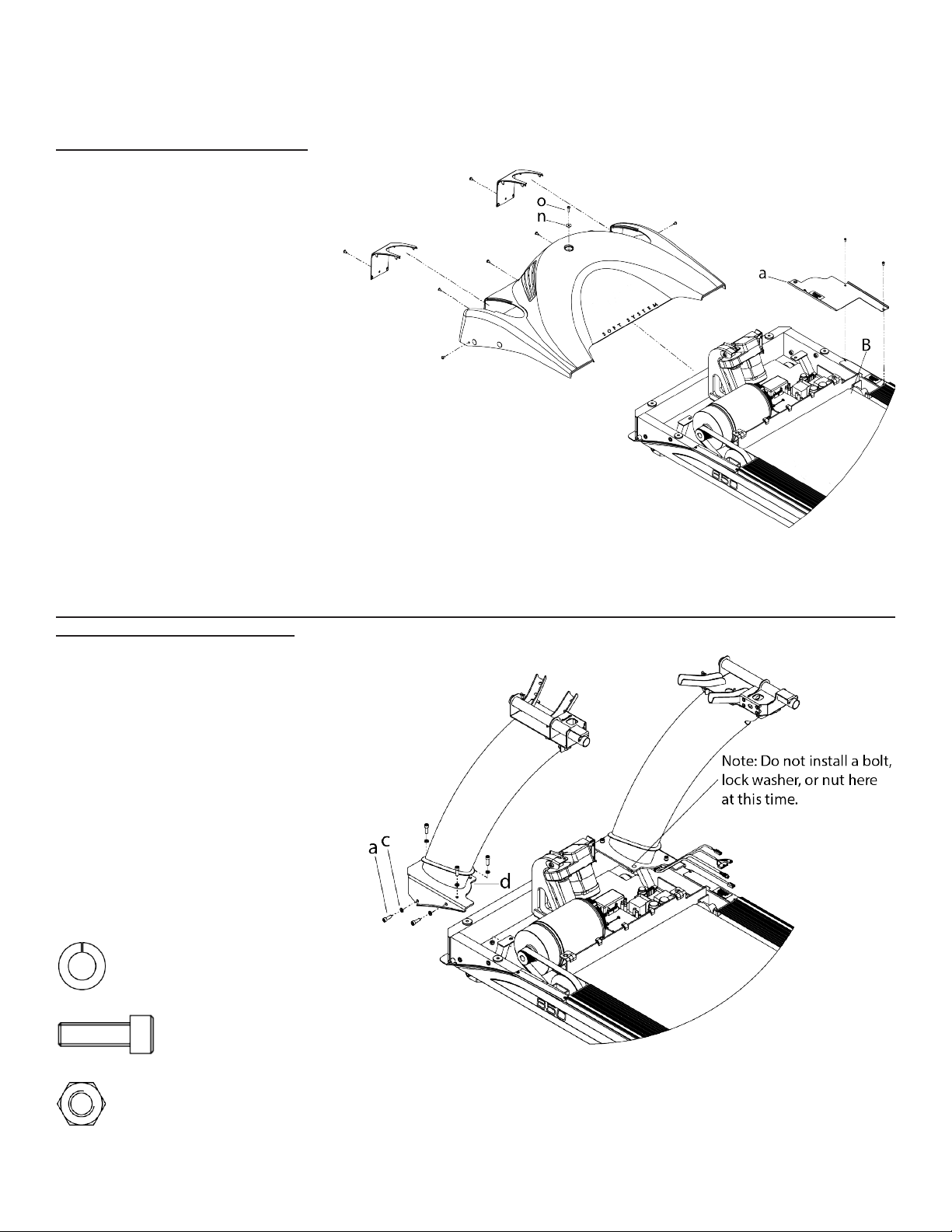
Step 1 Remove Motor Cover:
a) Remove the screw (o) and washer
(n)and then the seven remaining
identied screws from the motor
cover. Keep all motor cover hardware
for reassembling the motor cover to
the treadmill frame at Step 11.
b) While pulling the sides slightly
outward, remove the motor cover
from the treadmill frame (B) by
pulling upwards. You will feel
some snap catches release while
performing this step.
c) Remove the Drip Guard Assembly
(a) from the treadmill frame. Keep
all drip guard assembly hardware for
reassembling the drip guard assembly
to the treadmill frame at Step 4.
Step 2 Pedestal Installation:
a) Secure the pedestals to the treadmill
frame using nine M8 x 25 bolts (a),
nine M8 lock washers (c), and one M8
locknut (d) where shown.
Note: Do not fully tighten the hardware
used in this step yet.
Note: Ensure the pedestal cables are
routed between the treadmill frame and
pedestal support brace as shown.
Hardware Required:
Qty. 9 M8 Lock Washers
Qty. 9 Bolts M8 x 25
Qty. 1 Lock Nut M8
Truetness.com / 800.426.6570 / 636.272.7100 15 of 61
Page 16
CHAPTER 2: ASSEMBLY GUIDE
TREADMILL ASSEMBLY STEPS:
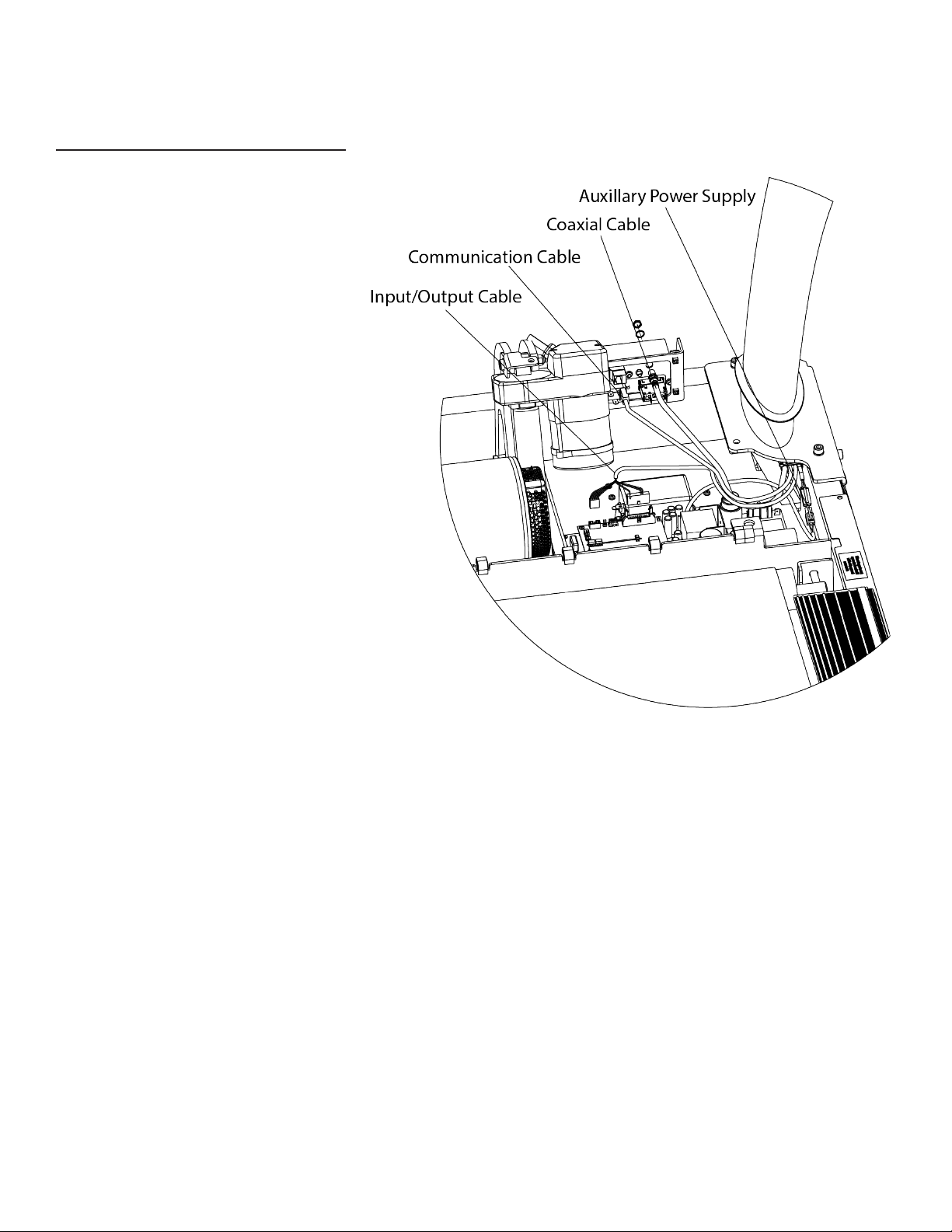
Step 3 Frame Cable Connections:
a) Route the cables exiting from the
right pedestal to the appropriate
connection point as shown. Cables will
be marked for easy identication.
b) Remove the nut and washer attached
to the coaxial cable as shown.
c) Pass the front of the coaxial cable
through the hole in the electrical panel
and reinstall the washer and nut on the
coaxial cable.
Truetness.com / 800.426.6570 / 636.272.7100
16 of 61
Page 17
CHAPTER 2: ASSEMBLY GUIDE
TREADMILL ASSEMBLY STEPS:
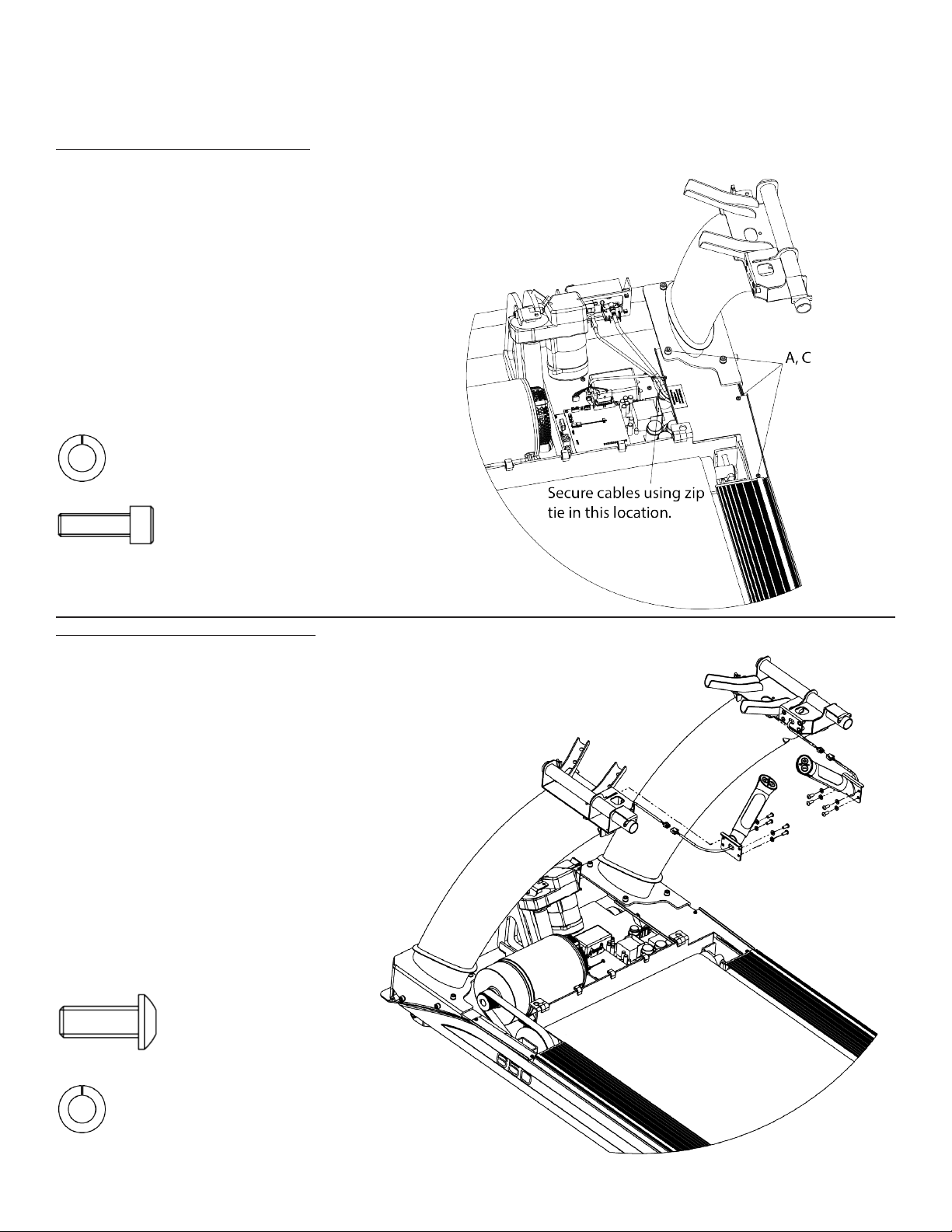
Step 4 Drip Guard Assembly:
a) Screw the M5 screws that were
removed earlier and a M8 x 25 bolt (A)
with a M8 split lock washer (C).
b) Secure all four right pedestal cables
to the drip guard assembly using the zip
tie in the location shown.
Note: Do not operate treadmill with
drip guard assembly removed.
Required Hardware:
Qty. 1 Lock Washer M8
Qty 1 Bolt M8 x 25
Step 5 Hand Grip Assemblies:
a) Connect the wire coming from
the bottom of the Contact Heart
Rate (CHR) grip assembly to the
corresponding wire located in the
pedestal arm as shown.
b) Secure each CHR grip assembly to
the pedestal arm with four screws and
four lock washers.
Note: Conrm each grip assembly is
assembled on the correct pedestal using
the le and right orientation stickers on
them.
Required hardware:
8 Bolt ¼”-20 x ⅝”
8 Lock Washer ¼”
Truetness.com / 800.426.6570 / 636.272.7100 17 of 61
Page 18
CHAPTER 2: ASSEMBLY GUIDE
TREADMILL ASSEMBLY STEPS:
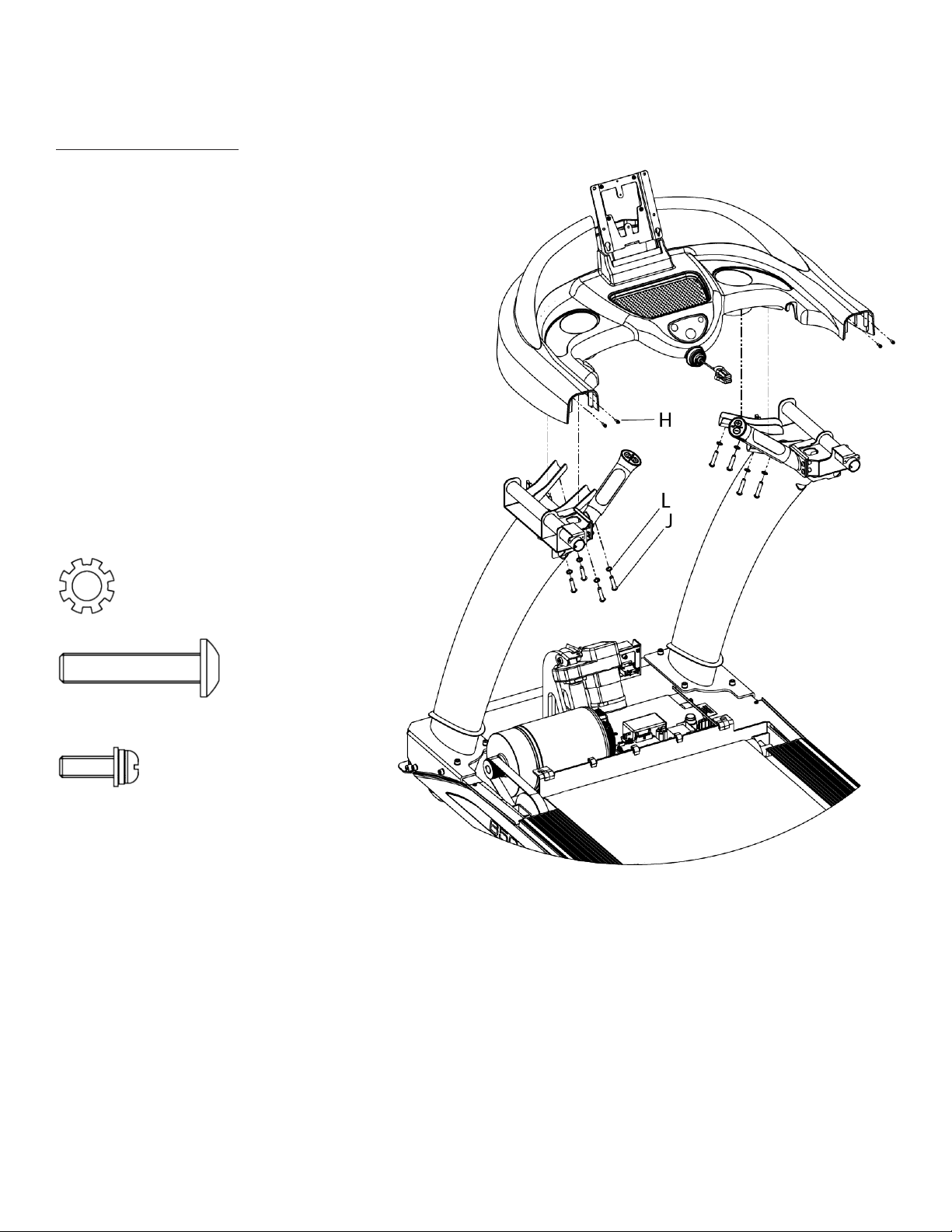
Step 6 Console Rack:
a) Install the console rack onto the pedestals
by resting the console rack tubing on top of
the pedestal tubing cradles.
CAUTION: Do not pinch cabling during
this step.
b) Install 8 Bolts 5/16”-24 x 1-1/2” and 8
external tooth lock washers through the
pedestal tubing cradle and console rack, but
do not tighten.
c) Tighten all hardware from steps 2a to 6c.
d) Install 4 M4 x 12 (H) screws and tighten.
Hardware Required:
8 Lock Washer M8
8 Bolts ⁄”-24 x 1-½”
4 Screws M4 x 12
Truetness.com / 800.426.6570 / 636.272.7100
18 of 61
Page 19
CHAPTER 2: ASSEMBLY GUIDE
TREADMILL ASSEMBLY STEPS:
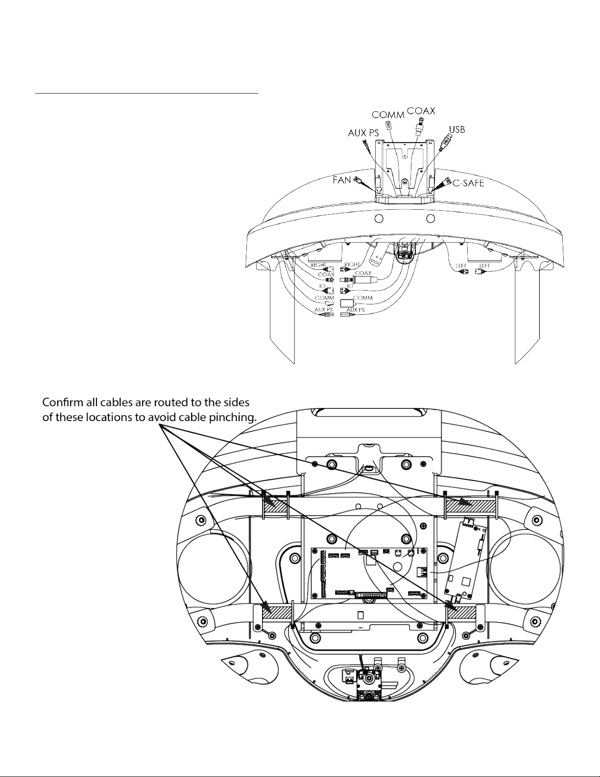
Step 7 Console Rack Cable Connections:
a) Connect all wires from the le and right
pedestal arms to the wires from the upper
console rack cover as shown (all cables will
be connected regardless of console option).
*Do not over torque the coax TV cable.
b) Route all cables into the underside of
the upper console rack cover as shown to
prevent wire pinching when installing the
bottom console rack cover.
Truetness.com / 800.426.6570 / 636.272.7100 19 of 61
Page 20

CHAPTER 2: ASSEMBLY GUIDE
TREADMILL ASSEMBLY STEPS:
Step 8 Lower Console Rack Cover:
a) Position the rear edge with the
long screw bosses slightly up inside
the console rack rst. Next, carefully
raise up the front edge while making
adjustments so the safety clip docking
bracket and long screw boss passes up
through the safety key mechanism.
Warning: Do not force the installation
of the bottom cover.
Hardware Required:
9 bolt M4 x 12
Step 9 Shoulder Trim Assembly:
a) Secure the le and right shoulder
trim assemblies to the console rack
using 14 bolts M4 x 12.
Hardware Required:
14 bolts M4 x 12
Truetness.com / 800.426.6570 / 636.272.7100
20 of 61
Page 21

CHAPTER 2: ASSEMBLY GUIDE
TREADMILL ASSEMBLY STEPS:
Step 10 : Handrail Assembly
a) Fully insert the handle and then
loosely install the bolts. While slightly
rotating the handle to best align the
seams and holding inwards, securely
tighten the bolts.
Warning: When starting the bolts, be
careful not to cross thread them.
Hardware Required:
4 bolts ¼”-20 x ¾”
Truetness.com / 800.426.6570 / 636.272.7100 21 of 61
Page 22

CHAPTER 2: ASSEMBLY GUIDE
TREADMILL ASSEMBLY STEPS:
Step 11 Power Inlet Assembly-220V (Optional):
a) Remove any power cords that might be
attached to the unit. Note: is step can be
performed without removing the motor
cover. e power inlet assembly can safely be
pulled out about 4 inches.
b) Remove the power inlet assembly-110V
from the power panel assembly. Keep the
three screws M5 x .8 for later in this step.
c) Install the 220V power inlet assembly as
follows: Disconnect the wires one at a time
as you transfer them from the original 110V
panel to the 220V panel. Note: e 220V
panel has a green, blue, and a brown color
dot on it. e colored dots correspond to
which color cables should be installed at
those locations. Begin moving the GREEN/
YELLOW wire over to the GREEN dot. Next,
move the BLUE wire over to the BLUE dot.
Lastly, move the BROWN wire over to the
BROWN dot.
d) Secure the power inlet assembly-220V to
the power panel assembly using three screws
M5 x .8.
Hardware Required:
3 screws M5 x .8
Truetness.com / 800.426.6570 / 636.272.7100
22 of 61
Page 23

CHAPTER 2: ASSEMBLY GUIDE
TREADMILL ASSEMBLY STEPS:
Step 12 220V Wiring Conversion(Optional):
a) See below for the wiring conversion to switch from 110V to 220V.
Truetness.com / 800.426.6570 / 636.272.7100 23 of 61
Page 24

CHAPTER 2: ASSEMBLY GUIDE
TREADMILL ASSEMBLY STEPS:
Step 13 Motor Cover:
a) Ensure the rubber trim
rings at the base of the
pedestal arms are slid
upwards near the console
rack and then rotated to
the side so that they will
stay upwards.
b) From the treadmill
user’s position, slide
the motor cover into
position over the motor
compartment. While
slightly exing the sides
outwards, carefully lower
the motor cover into
position. Try to avoid
dislodging the rubber bolt
head caps. Next, push
the motor cover rmly
downwards to engage
the two snap action
engagement clips.
Note: If a rubber cap came out, ex the motor cover outwards at this time and reinsert the cap before installing
the side screws in the motor cover.
Truetness.com / 800.426.6570 / 636.272.7100
24 of 61
Page 25

CHAPTER 2: ASSEMBLY GUIDE
TREADMILL ASSEMBLY STEPS:
Step 13 Motor Cover (continued):
c) Reinstall screw O and
washer N at this time.
d) Flex the sides of the
motor cover as needed
to slip the rubber bolt
covers over the heads of
the four bolts, reinstall the
M5 screws on the le and
right sides.
e) Reinstall the three M5
screws across the front
side of the motor cover.
f) Reinstall the two motor
cover inserts and their M5
screws.
Note: To properly engage
the two small clips at the
bottom of the inserts,
ex upwards and then
carefully guide in the clips
as the part is lowered.
g) Rotate and lower the rubber trim rings into proper position next to the motor cover. Engage their retaining
stems into the motor cover inserts. Note: e trim rings can rotate 180 degrees. In one position, they will t
without gap s. In the wrong orientation, they will not t closely to the motor cover.
h) Install the cap-motor cover screw that is located in the hardware kit.
Truetness.com / 800.426.6570 / 636.272.7100 25 of 61
Page 26

CHAPTER 2: ASSEMBLY GUIDE
TREADMILL ASSEMBLY STEPS:
Step 14 Safety Key:
a) Locate the Safety Key attached to the
console rack.
b) Attach the Safety Key clip to the
anchor plate located on the console
rack (when not working out).
c) Attach the safety key clip to clothing
at the beginning of any workout.
CAUTION: Read treadmill Owner’s
Manual before attempting any workout.
Truetness.com / 800.426.6570 / 636.272.7100
26 of 61
Page 27

CHAPTER 2: ASSEMBLY GUIDE
TREADMILL ASSEMBLY STEPS:
Step 15A Safety Key (E-Stop) Overview:
Attach the safety clip to your clothing before each workout and when equipment is in use to ensure an
immediate halt of all treadmill belt activity if the user is unable to continue.
4
3
12
Safety Key Feature Number
Safety Key Clip 1
Safety Key Pull
Cord
Safety Stop 3
Console Rack 4
2
Truetness.com / 800.426.6570 / 636.272.7100 27 of 61
Page 28

CHAPTER 2: ASSEMBLY GUIDE
TREADMILL ASSEMBLY STEPS:
Step 15B Safety Key (E-Stop) Usage:
Safety Key (E-Stop) Disengaged:
Shown to the le is the disengaged position
of the safety key (e-stop).
When the equipment is in use or the user
is standing on the belt not in use, the safety
key clip must be attached to the user’s
clothing. is allows the safety stop to be
engaged if the safety clip attached to the
user pulls the safety key pull cord taught,
thus immediately halting all treadmill belt
activity.
Note: e safety key pull cord length allows
free range of motion for the user within
the normal workout parameters identied
within this owner’s manual.
Safety Key (E-Stop) Engaged:
Shown to the le is the engaged position of
the safety key (e-stop). Note the safety stop
outer sleeve that covers the safety stop to
denote the engaged position.
When the safety stop is engaged, all
treadmill belt activity will cease and the
following error message will appear on the
console advising the safety stop is engaged
“INSERT SAFETY KEY.”
To remove the console error message and
place the safety stop back in the disengaged
position, push the safety stop in once.
Note: You will be taken to the workout
conclusion screen once the safety stop is
switched back to the disengaged position.
Truetness.com / 800.426.6570 / 636.272.7100
28 of 61
Page 29

CHAPTER 2: ASSEMBLY GUIDE
TREADMILL ASSEMBLY STEPS:
Step 16A Console Mast Assembly:
Place the two bottom console mounting screws
inside the bottom keyholes on the console mast
assembly. Partially thread the two top console
mounting screws into the console. Fully tighten all
four console mounting screws.
Note: Ensure all cable connections are routed
inside the console mast assembly to prevent cable
pinching.
Note: Refer to the respective console manual
included with your console for wiring connections.
Hardware Required:
Part Number 00567800
Qty 4: M5 x 12 bolts
Step 16B Rear Console Cover Assembly:
a) Secure the rear console cover assembly to
the console mast assembly using two bolts
M5 x 10.
CAUTION: Make sure cabling is NOT
pinched during installation.
Note: For specic console assembly
instructions, see the corresponding
section at the end of Chapter 2: Assembly
Instructions.
Hardware Required:
Qty. 2: M5 x 10 bolts
Truetness.com / 800.426.6570 / 636.272.7100 29 of 61
Page 30

CHAPTER 2: ASSEMBLY GUIDE
TREADMILL ASSEMBLY STEPS:
Step 17 Rear Foot Leveling:
a) Ensure treadmill incline rack
wheels and rear feet are resting on
the oor and not on cardboard,
packaging, etc.
b) Using a 15/16 inch open
end wrench, loosen nut A on
Right Rear Foot (only side
adjustable).
c) Using a level or estimating by sight,
turn section B of foot clockwise, or
counter-clockwise, using a 7/8 inch
open end wrench to level the rear of
treadmill.
d) Tighten nut A until it is secured
against bottom of treadmill.
Note: e recommended gap between
(A) and (B) is 1/4” on a at oor.
Step 18 Power Cord Retainer:
a) Install the power cord retainer assembly in
the order shown, but do no tighten.
b) Rotate power cord retainer down and
tighten the screw to push the retainer up
against the power cord.
Hardware Required:
1 spacer
Note: e 110V spacer is 1-3/4” long.
e 220V spacer is 1-1/4” long.
110V
conguration
1 retainer-power cord
1 bolt M5 x 60
220V
conguration
Truetness.com / 800.426.6570 / 636.272.7100
30 of 61
Page 31

CHAPTER 2: ASSEMBLY GUIDE
TREADMILL ASSEMBLY STEPS:
Step 19 Power Cord Installation:
CIRCUIT BREAKER: In the event
the current drawn by the treadmill
exceeds a specied value, the Circuit
Breaker portion of the power on/o
switch will operate. e rocker lever will
automatically release and position itself
to a position half way between on and o,
thus opening the power circuit.
If this should occur, please wait 10
minutes and then reset the Circuit
Breaker by rocking the power switch fully
to the OFF position (O), and then rocking
the power switch back to the ON position
(-). If it does not reset, or the Circuit
Breaker operates again udner normal use,
contact True Fitness at 1-800-883-8783.
Note: e above picture shows the power
switch in the OFF position (O) for reference.
Circuit Breaker Positions
220V 110V
Truetness.com / 800.426.6570 / 636.272.7100 31 of 61
Page 32

CHAPTER 2: ASSEMBLY GUIDE
TREADMILL ASSEMBLY STEPS:
Step 20 Leveling Feet-Decline Kit(Optional):
a) Remove the leveling feet from
the treadmill frame as shown.
Truetness.com / 800.426.6570 / 636.272.7100
32 of 61
Page 33

CHAPTER 2: ASSEMBLY GUIDE
TREADMILL ASSEMBLY STEPS:
Step 21 Leveling Feet-Decline Kit(Optional):
a) Secure the optional decline kit to the treadmill frame in
the identied areas using four bolts 1/4”-20 x 3/4” per kit.
b) Screw the leveling feet into the optional decline kit
holes as shown.
Note: e bracket is le and right side sensitive so conrm
you are using the correct bracket.
Hardware Required:
8 bolts 1/4”-20 x 3/4”
Truetness.com / 800.426.6570 / 636.272.7100 33 of 61
Page 34

CHAPTER 2: ASSEMBLY GUIDE
TREADMILL ASSEMBLY STEPS:
Step 22 Prepare Treadmill (Optional):
a) Power on the treadmill and press the Quick Access key located on the le Contact Heart Rate grip to increase
the incline to six percent. Remove the power cord from the wall receptical, which provides ample working space
for this installation. Place protective padding on the oor and carefully place the treadmill on its le side on the
protective padding. Loosen the 11 notated screws already assembled on the treadmill frame and position the
corresponding 11 slots on the power cord managment hardware between the 11 screws and the treadmill frame.
Note: e TC900 should already be assembled before proceeding with Step 1 (Preparing Treadmill).
Note: Position the wire retainer clips as shown below.
Pre-assembled treadmill frame screws for cord management hardware
Cord Management Hardware
Wire Retainer Clips
Truetness.com / 800.426.6570 / 636.272.7100
34 of 61
Page 35

CHAPTER 2: ASSEMBLY GUIDE
TREADMILL ASSEMBLY STEPS:
Step 23 Core Management Hardware Alignment (Optional):
Position the cord management hardware to allow seamless transition with the treadmill frame when viewed
from the outside. Tighten the 11 screws from Step 1 (Prepare Treadmill) to lock the core management hardware
position in place.
Step 24 Guide Channel (Optional):
Insert the coaxial, ethernet, and power cord cables into the guide channel of the cord management hardware.
Route the three cables through the two wire retainer clips by untwisting and enlarging the gap between both
prongs. Return the wire retainer clips to the neutral position aer all three cables are routed through.
Note: To optimize cable retention in the guide channel of the core management hardware, insert the three cables
in the following order based on cord diameter: Ethernet, coaxial, and power cable.
Truetness.com / 800.426.6570 / 636.272.7100 35 of 61
Page 36

CHAPTER 2: ASSEMBLY GUIDE
TREADMILL ASSEMBLY STEPS:
Step 25 Exit Location (Optional):
Shown below is the suggested exit location of the cables near the rear leveling foot, but the cables may exit at
other locations from the guide channel depending on the location of the corresponding outlet(s).
Note: To prevent cord entanglement with the running belt and rollers and reduce injury from tripping hazards,
the cords must not exit from or cross over the rear of the treadmill.
Step 26 Treadmill Neutral Position (Optional):
Conrm the cables are routed correctly through the two wire retainer clips to prevent cable pinching above the
incline rack wheels. Position the treadmill upright to restore it to the neutral position. Connect the male ends of
the Ethernet, coaxial, and power cables to the corresponding outlet(s). Restore the treadmill deck incline grade
to zero percent while conrming the three cables maintain correct positioning along the guide channel in the
cord management hardware.
Truetness.com / 800.426.6570 / 636.272.7100
36 of 61
Page 37

CHAPTER 3: PRODUCT OVERVIEW
TREADMILL OVERVIEW:
Quick Access Keys
Contact Heart
Rate Pad
Safety (E-Stop) Key
Contact Heart
Rate Pad
Console Assembly
Belt Adjustment Bolts
Leveling Feet
Straddle Covers
Belt
On/O Switch, Circuit Breaker,
and Power Cord
Truetness.com / 800.426.6570 / 636.272.7100 37 of 61
Page 38

CHAPTER 3: PRODUCT OVERVIEW
TREADMILL OVERVIEW:
Console Assembly:
e console allows the user to set up a workout program and control the Alpine Runner during a workout (For console
overview and operation instructions refer to chapter 4).
Quick Access Keys:
Allows the user to quickly start, stop and wake the Alpine Runner or make fast, convenient adjustments to the incline level
or speed of the treadmill.
Contact Heart Rate Pads:
Allows the user to check their heart rate without wearing a wireless chest strap.
*For increased safety and accuracy this feature should only be used when the belt speed is below 4 mph.
Safety (E-Stop) Key:
A tethered safety device designed to attach to both the user and the Alpine Runner console. Removal of the key from the
console will stop belt motion to prevent injury in an emergency.
*e safety key must be in place on the Alpine Runner, and should be attached to the user’s clothing. e Alpine Runner
will not operate if the safety key is not attached to the Alpine Runner.
Belt:
e moving surface of the Alpine Runner on which the user walks or runs.
Straddle Covers:
Stationary covers on either side of the belt, which allows the user to safely straddle the belt during startup or in the event of
an emergency.
Belt Adjustment Bolts:
An adjustment system that allows the users to adjust the belt tracking and tension as needed.
On/O Switch:
Allows users or faculty to turn the power on or o to the Alpine Runner.
Circuit Breaker:
A safety device designed to protect the Alpine Runner from excessive electrical current.
Power Cord:
Delivers power from the wall outlet to the Alpine Runner.
Leveling Feet:
An adjustable system used to aid in the leveling the Alpine Runner.
Truetness.com / 800.426.6570 / 636.272.7100
38 of 61
Page 39

CHAPTER 4: CARE & MAINTENANCE
CARE & MAINTENANCE:
It is important to perform the minor maintenance tasks described in this section. Failure to maintain the treadmill as
described here could void the TRUE Fitness Warranty. To reduce the risk of electrical shock, always unplug the unit from
its power source before cleaning or performing any maintenance tasks.
Inspection:
TRUE Fitness is not responsible for performing or scheduling regular maintenance or inspections. Users should inspect the
treadmill daily. Check for worn, frayed or missing safety lanyards. Replace missing or worn safety lanyards immediately.
Do not exercise on the treadmill without attaching the safety clip to your clothing. Look and listen for slipping belts,
loose fasteners, unusual noises, worn or frayed power cords, and any other indications that the equipment may be in need
of service. If any of these are noticed, obtain service. Do not attempt to use the treadmill until proper service has been
performed or damaged parts have been replaced.
Important:
If you determine that the treadmill needs service, make sure that the treadmill cannot be used inadvertently. Turn the unit
o, and then unplug the power cord from its power source. Remove the magnetic safety key and safety clip and store it in a
safe place. Make sure other users know that the treadmill needs service.
*To order parts or to contact a TRUE Authorized Service representative, please visit www.truetness.com.
CLEANING THE EQUIPMENT:
Aer Each Use:
• Use GymWipes™ Antibacterial wipes or spray a solution of 30 parts water to 1 part mild detergent to dampen a so
cloth and wipe all exposed surfaces.
• Use a LCD/screen cleaner or spray a solution of 1 part 91% isopropyl alcohol and 1 part water to dampen a so cloth
and wipe the surface of the console. is helps remove ngerprints, dust, and dirt.
Week l y :
• Vacuum any dust or dirt that might have accumulated under or around the treadmill, any motor cover vents and under
the straddle covers. Clogged air vents can prevent adequate cooling to the drive motor, incline motor, and motor
control board causing a shortened life.
• Check for proper running belt alignment and tension. If running belt adjustment is required, see sections “RUNNING
BELT ALIGNMENT” and “TENSIONING THE RUNNING BELT” in the following pages.
CAUTION:
Do not use any acidic cleaners. Doing so will weaken the paint or powder coatings and may void the TRUE Fitness
Warranty. Never pour water or spray liquids on any part of the treadmill. Allow the treadmill to dry completely before
using. Frequently vacuum the oor underneath the unit to prevent the accumulation of dust and dirt, which can aect the
smooth operation of the unit. Use a so nylon scrub brush to clean the running belt. Do not clean directly underneath the
treadbelt. Most of the working mechanisms are protected inside the motor cover and base of the treadmill. However, for
ecient operation, the treadmill relies on low friction. To keep the friction low, the unit’s running belt, staging platforms,
and internal mechanisms must be as clean as possible.
Truetness.com / 800.426.6570 / 636.272.7100 39 of 61
Page 40

CHAPTER 4: CARE & MAINTENANCE
RUNNING BELT ALIGNMENT:
Proper belt alignment allows the belt to remain centered and ensures smooth operation. Realigning the belt takes a few
simple adjustments. If you are unsure about this procedure, call the TRUE Service Department.
CAUTION:
Special care must be taken when aligning the running belt. Turn o the treadmill while adjusting or working near the rear
roller. Remove any loose clothing and tie back your hair. Be very careful to keep your ngers and any other object clear
of the belt and rollers, especially in front of the roller and behind the deck. e treadmill will not stop immediately if an
object becomes caught in the belt or rollers.
CAUTION:
If you hear any chang or the running belt appears to be getting damaged, stop the running belt immediately by pressing
the STOP key. Contact the TRUE Service Department. Walk around to the rear of the unit and observe the belt for a few
minutes. e belt should be centered on the running deck. If the belt dris o center, you must make adjustments.
Important:
Failure to align the belt may cause the belt to tear or fray, which may not be covered under the TRUE Fitness Warranty. To
stop the running belt, press the STOP key. Turn the treadmill o.
CAUTION:
For your safety, use the power switch to turn o the treadmill before making any adjustments. Do not adjust the running
belt when someone is standing on the unit.
CAUTION:
Do not turn the adjusting bolt more than 1/4 turn at a time. Over tightening the bolt can damage the treadmill. If you are
unsure how to adjust the running belt, call the TRUE Service Department.
Note: When running belt is properly aligned, people can see
the belt locating at the center of the belt alignment slot.
e slot is located on the rear roller guard.
If the running belt is too far to the right side:
• Locate the belt adjustment bolts in the rear end caps of the
treadmill. (To determine le and right, stand at the rear of
the treadmill and face the display).
• Using the appropriate size Allen wrench or socket turn the
RIGHT adjustment bolt clockwise ¼ turn.
• Turn the treadmill on and start the belt at 3mph keeping o
the unit.
• Allow 2 minutes for the belt to adjust itself.
• Repeat the above steps if additional adjustment is necessary.
Truetness.com / 800.426.6570 / 636.272.7100
40 of 61
Page 41

CHAPTER 4: CARE & MAINTENANCE
If the running belt is too far to the le side:
• Locate the belt adjustment bolts in the rear end caps of the
treadmill. (To determine le and right, stand at the rear of the treadmill and face the display).
• Using the appropriate size Allen wrench or socket turn the LEFT adjustment bolt clockwise ¼
turn.
• Turn the treadmill on and start the belt at 3mph keeping o the unit.
• Allow 2 minutes for the belt to adjust itself.
• Repeat the above steps if additional adjustment is necessary.
Note: Aer the running belt alignment is complete, conrm the Allen wrench has been removed from the adjustment bolt
in the front belt cover before further use.
TENSIONING THE RUNNING BELT:
If there is a slipping or jerking sensation when running on the treadmill, the running belt may require tightening. In most
cases the belt has stretched from use. Tensioning the belt takes a few simple adjustments. If you are unsure about this
procedure, call the TRUE Service Department.
• Locate the belt adjustment bolts in the front belt cover.
• Remove the rubber cover plugs.
• Using the appropriate size Allen wrench or socket,
turn BOTH adjustment bolts clockwise ¼ turn.
• Turn the unit on, start the belt, and check if the slipping
continues.
• Repeat the above steps if additional adjustment is necessary.
Note: Aer the running belt tensioning is complete, conrm
both Allen wrenches have been removed from the adjustment
bolts in the front belt cover before further use.
BELT LUBRICATION:
For commercial use over 20 hours per week, TRUE recommends lubricating every three months.
• Locate the belt adjustment bolts in the front belt cover
• Remove the rubber cover plugs.
• Loosen the belt adjustment bolts in the front belt cover.
• Li the belt and apply the lubricant to the center of the
deck.
• Center and re-tension the belt using the directions above.
• Walk on the unit at 2MPH for about 60 seconds to spread
the lubricant evenly through the belt and deck.
*Please contact your dealer or visit www.truetness.com to
obtain the proper lubricants.
Truetness.com / 800.426.6570 / 636.272.7100 41 of 61
Page 42

CHAPTER 4: CARE & MAINTENANCE
LEVELING THE EQUIPMENT:
is equipment has adjustable front leveling feet to make sure that the running surface
is level. If the unit is placed on an uneven surface, adjusting the front feet can help, but may
not completely compensate for extremely uneven surfaces.
OTHER SCHEDULED PREVENTIVE MAINTENANCE:
TRUE recommends that quarterly scheduled maintenance be performed by a qualied service technician. Please contact
your dealer or visit www.truetness.com to contact a local TRUE authorized service technician.
Scheduled Preventive Maintenance:
• Record time, distance and hours from the console.
• Check error log in console.
• Check running belt and drive belt tension and tracking.
• Remove the motor cover and vacuum any debris out of the drive motor, speed sensor cage, motor control
board and heat sink motor compartment.
• Move treadmill and vacuum underneath.
• Lubricate elevation pivot points including rear stabilizing feet and the li motor screw.
• Lubricate walking belt and deck.
• Inspect all fasteners.
• Inspect all electrical connections.
• Inspect all components for abnormal or premature wear.
CAUTION:
Use only TRUE Fitness certied service providers.
LONG TERM STORAGE:
When the treadmill is not in use for any length of time, turn it o. Make sure that the power cord is unplugged from the
power source and is positioned so that it will not become damaged or interfere with people or other equipment.
Storing the Chest Strap:
Store the chest strap in a place where it remains free of dust and dirt such as, in a closet or drawer. Be sure to protect the
chest strap from extremes in temperature. Do not store it in a place that may be exposed to temperatures below 32° F
(0° C). To clean the chest strap, use a sponge or so cloth dampened in mild soap and water. Dry the surface thoroughly
with a clean towel.
Truetness.com / 800.426.6570 / 636.272.7100
42 of 61
Page 43

CHAPTER 5: CUSTOMER SERVICE
CONTACTING SERVICE:
TRUE Fitness recommends that you gather the serial number, model number, and a brief description of the reason for the
request. Aer information has been gathered you may choose to contact your selling dealer or local service company to
set an appointment. (If you are not familiar with who is in your area, you may visit our website at www.truetness.com and
use our dealer locator to obtain the contact information for the closest dealer).
You may also contact TRUE Fitness’ customer support team by calling 800.883.8783 or e-mailing us at
service@truetness.com Monday – Friday during normal business hours.
TRUE FITNESS SERVICE DEPARTMENT
865 HOFF ROAD
ST. LOUIS, MO 63366
1.800.883.8783
HOURS OF OPERATION: 8:30 A.M. - 5:00 P.M. CST
E-MAIL: service@truetness.com
CONTACTING SALES:
Interested in TRUE Products? Please contact us with any sales or product inquires so that we may direct you to the
appropriate sales representative to answer your questions.
TRUE FITNESS HOME OFFICE
865 HOFF ROAD
ST. LOUIS, MO 63366
1.800.426.6570
HOURS OF OPERATION: 8:30 A.M. - 5:00 P.M. CST
E-MAIL: sales@truetness.com
Truetness.com / 800.426.6570 / 636.272.7100 43 of 61
Page 44

CHAPTER 5: CUSTOMER SERVICE
REPORTING FREIGHT OR PARTS DAMAGE:
Unfortunately, sometimes materials can be damaged during shipment. If materials are damaged during shipment, please
follow the guidelines below to determine the appropriate process for you to follow in case of damages.
Severe Damage:
Obvious damage to external packaging / internal product. Please refuse the shipment and it will be returned to TRUE
Fitness by the carrier. Contact the TRUE Fitness customer support team by calling 800.883.8783 or sales support team by
calling 800.426.6570 Monday-Friday during normal business hours to notify us that the shipment has been refused. Once
we have received the damaged shipment, a replacement shipment will be sent to you. Only refuse the damaged piece if the
shipment is multiple boxes.
Slight Damage:
e box may have minimal damages and you are not sure if the actual product is damaged or not. You must sign the bill
of lading as damaged when accepting the shipment. Once you have opened the box and you have determined something
is indeed damaged please gather the serial number, model number, description and photos of damages. Please make sure
the photos include the damaged product as well as the damaged box the product arrived in. Contact the TRUE Fitness
customer support team by calling 800.883.8783 or sales support team by calling 800.426.6570 Monday-Friday during
normal business hours.
Concealed Damage:
You may receive a shipment that looks intact and discover once the box has been opened that there are hidden damages.
Please notify the carrier immediately. We will not be able to le a claim if the carrier is not notied in a timely manner.
Once you have called the carrier you will need to gather the serial number, model number, description and photos of
damages. Contact the TRUE Fitness customer support team by calling 800.883.8783 or sales support team by calling
800.426.6570 Monday-Friday during normal business hours.
Truetness.com / 800.426.6570 / 636.272.7100
44 of 61
Page 45

CHAPTER 6: ADDITIONAL INFORMATION
TROUBLESHOOTING GUIDE:
is troubleshooting guide is intended to assist in diagnostics only and is not all inclusive. Technical specications, error
codes and programming are subject to change without notice. TRUE accepts no liability for any damage or loss suered by
persons whom rely wholly or in part on any description or statement contained within this manual. Please visit
www.TRUEtness.com to obtain the most recent version of all manuals and contact the TRUE Service Department at 800883-8783 for assistance with troubleshooting and diagnostics.
Malfunction Possible Cause Corrective Action
Unit turned o Verify the On/O switch is at the ON position
Damaged power cord Replace power cord
Power cord not fully seated in socket Inspect power connection at the unit and outlet
No Power
No power at outlet Using a voltmeter verify power at outlet
e location of the circuit breaker is next to the
Tripped circuit breaker
On/O switch. Verify the circuit breaker is not
open. If the breaker is open reset.
Unit resets or pauses
randomly
Walking belt is o
center
Walking belt hesistates
or slips when stepping
Rubbing sound from
treadmill when in
operation
Damaged power cord Replace power cord
Power cord not fully seated in socket Inspect power connection at the unit and outlet
Safety e-stop key not fully engaged Re-engage the safety/e-stop key to the console
Insucient power
Error code is displayed on console
Pinched or loose main communication cable
No User Present displayed on screen
Uneven oor
Adjust belt tracking See Chapter 5: Centering the Running Belt
Adjust belt tension See Chapter 5: Tensioning the Running Belt
Lubricate running belt See Chapter 5: Treadmill Lubrication
Walking belt is rubbing a straddle cover
Foreign object may be stuck under walking
belt
Foreign object may be stuck in motor
compartment
Roller bearings may be damaged
Drive motor may be damaged
Verify output voltage from 20A outlet with a
voltmeter
Contact TRUE Fitness Customer
User weight must be over 90lbs. Verify No
User Present settings in console.
Adjust treadmill with rear leveling feet. See
Chapter 5: Running Belt Alignment
Adjust belt tracking. See Chapter 5: Centering
the Running Belt
Inspect under the unit. Remove and object that
may be under the unit.
Contact TRUE Fitness Customer Service
Department
Drive belt may be misaligned
Truetness.com / 800.426.6570 / 636.272.7100 45 of 61
Page 46

CHAPTER 6: ADDITIONAL INFORMATION
Malfunction Possible Cause Corrective Action
Heart rate is displaying
erratically or not
displaying
Transmitter belt contacts are not making
good contact with the skin
Contacts on the transmitter belt are not
moist
Transmitter belt is not within 3 feet (1 meter)
of the heart rate receiver
e battery inside the transmitter belt is
depleted
Another user wearing a compatible
transmitter strap is within 3 foot (1 meter) of
the unit
Environmental interference from high
voltage power lines
Environmental interference from
computers
Environmental interference from motor
driven appliances
Environmental interference from cell or
cordless phone
Environmental interference from Wi-Fi
router
Re-adjust the transmitter belt so that it is in full
contact with the skin
Moisten the contacts on the transmitter belt
Adjust your position on the belt so that you
are within 3 feet (1 meter) of the console
Replace the transmitter belt with a
compatible transmitter belt
Move the units so that there is more space
in-between units
Move the unit to another position
within the room or move the cause of
the interference until heart rate reading
are stable. If the probable source of
interference is plugged into the same outlet
move the suspect source to another outlet.
Fault Code Category Description Cause Corrective Action
Power cycle
Corrupt soware
Re-congure console
Re-install soware/
rmware
Contact dealer or TRUE
Power cycle
Re-congure console
Re-install soware/
rmware
Fault CN00: Corrupted
Console Conguration
Fault CN01: Internal
Fault
Console
Console
Corrupted brainboard
conguration - fails integrity
check
Math error - soware
Firmware and
soware versions are
not compatible
Console Congure
Incorrectly
Corrupt Soware
Contact dealer or TRUE
Power cycle
Re-congure console
Fault CN02:
Invalid Console
Conguration
Console
e product conguration
data has failed validation
checks
(incline ranges make no
sense, etc.)
Console Congure
Incorrectly
Incline Motor out of
range
Loose Cable
Contact Dealer or TRUE
service
service
service
Truetness.com / 800.426.6570 / 636.272.7100
46 of 61
Page 47

CHAPTER 6: ADDITIONAL INFORMATION
Fault CN03:
Stuck Key
Fault CN04:
Lower Board
Comm Fault
(Treadmill
Only)
Fault CN05:
No Lower
Control
Fault CN06:
Cong
Mismatch
Fault CN07:
Calibration
Timeout
Fault CN08:
Calibration
Failed -
Lower Limit
Not Reached
Console
Console
Console
Console
Console
Console
Membrane Key stuck
down/closed
Brainboard fails
to receive timely
communication
responses from lower
board - Fault aer 3
retries
No lower board
connected to console
- detection wires not
connected.
Console is congured
for a product dierent
than that to which it is
connected.
Incline Calibration was
not able to complete
within allowed time.
During incline
calibration, the incline
stalled before reaching
what should be the
lower limit.
Membrane key is
damaged
Loose Cable
Smart Card
Console
Loose Cable
Console Congure
Incorrectly
Console Congure
incorrectly
Loose Cable Check cable connections
Low AC Line Voltage
Console displays Fault
Calibration not saved.
Incline disabled.
Incline Potentiometer
value out of range
Contact dealer or TRUE service
Power cycle
Check cable connections
Contact dealer or TRUE serviceMCB
Power cycle
Check Cable Connection
Re-congure console
Power cycle
Re-congure console
Retry calibration
Verify AC Voltage at Outlet
Power cycle
Check cable connections
Run incline calibration
Contact dealer or TRUE service
Fault CN09:
Insert Safety
Key
Fault CN10:
E-Stop Fault
Fault CN24:
BB Comm
Fault
Fault CN25:
Firmware
Mismatch
Console
Console
Console
Console
Safety Key not engaged Re-insert safety key
Emergency Circuit
opened
A test of the emergency
circuit has failed
SBC cannot
communicate with
Brainboard
Firmware on brainboard
not compatible with
SBC soware
Loose Cable Check cable connections
Switch Damaged Contact dealer or TRUE service
Console Catch Power cycle
Safety Key not engaged Reinsert safety key
Loose Cable Check cable connections
Switch Damaged Contact dealer or TRUE service
Power cycle
Console
Contact dealer or TRUE service
Power cycle
Corrupt soware
Recongure Console
Firmware and soware
versions are not
compatible
Re-install soware/rmware
Contact dealer or TRUE service
Truetness.com / 800.426.6570 / 636.272.7100 47 of 61
Page 48

CHAPTER 6: ADDITIONAL INFORMATION
High Belt Deck Friction Lubricate treadbelt
Fault SP01:
Belt Under
Speed
Fault SP02:
Belt Over
Speed
Fault SP03:
Belt Over
Accel
Fault SP04:
No Speed
Signal
Speed
Speed
Speed
Speed
Tread motor rpm is
below target rpm
Tread motor rpm is
higher than target rpm
Tread belt speed
increasing too quickly
Speed sensor is not
providing speed data
High Belt Tension Contact dealer or TRUE service
Low Line Voltage
Dirty or misaligned speed
sensor
High Belt Deck Friction
Line Voltage Check AC line voltage
Dirty or misaligned speed
sensor
User is holding belt back Do not try to stop belt
High Belt Deck Friction Lubricate treadbelt
Dirty or misaligned speed
sensor
Dirty or misaligned speed
sensor
High Belt Deck Friction
Check drive belt and walking belt
tension
Contact dealer or TRUE service
Lubricate treadbelt
Contact dealer or TRUE service
Contact dealer or TRUE service
Contact dealer or TRUE service
Contact dealer or TRUE service
Lubricate treadbelt
Contact dealer or TRUE service
Fault IN01:
Incline Stall
Fault IN02:
Incline Out
of Range
Fault IN03:
Incline Run
Fault
Incline
Incline
Incline
Incline not moving
when commanded
Incline value is out of
the calibrated range -
does not occur during
calibration
Incline moving when
not commanded
Truetness.com / 800.426.6570 / 636.272.7100
Low Line Voltage Check AC line voltage
Console displays Fault
Calibration not saved. Incline
disabled.
Incline Potentiometer value
out of range
Acme Nut Jammed
Motor Bearings
Console displays Fault
Calibration not saved. Incline
disabled.
Incline Potentiometer value
out of range
Console displays Fault
Calibration not saved. Incline
disabled.
Incline Potentiometer value
out of range
Check cable connections
Contact dealer or TRUE service
Check cable connections
Contact dealer or TRUE service
Check cable connections
Contact dealer or TRUE service
Power cycle
Run incline calibration
Power cycle
Run incline calibration
Power cycle
Run incline calibration
48 of 61
Page 49

CHAPTER 6: ADDITIONAL INFORMATION
Fault IN04:
Incline Max/Min
Fault A101:
Motor Controller
Fault
Fault A102:
Motor
Controller
Fault
Fault A103:
Motor
Controller
Fault
Fault A104:
Motor
Controller
Fault
Fault A105:
Motor
Controller
Fault
Fault A106:
Motor
Controller
Fault
Fault A107:
Motor
Controller
Fault
Incline value is out of
Incline
AC MCB 2.5 VDC Ref Status Motor Control Board
AC MCB 1.65 VDC Ref Status Motor Control Board
AC MCB
AC MCB
AC MCB Phase C Circuit Open
AC MCB Phase B Circuit Open
AC MCB Phase A Circuit Open
expected operating
range - may indicate
that it is disconnected.
Phase B Current
Sensor
Phase A Current
Sensor
Console displays Fault
Calibration not saved.
Incline disabled.
Incline Potentiometer
value out of range
Loose Cable Check cable connections
Motor Control Board Contact dealer or TRUE service
Loose Cable Check cable connections
Motor Control Board Contact dealer or TRUE service
Loose Cable Check cable connections
Motor Control Board Contact dealer or TRUE service
Loose Cable Check cable connections
Motor Control Board Contact dealer or TRUE service
Loose Cable Check cable connections
Motor Control Board Contact dealer or TRUE service
Power cycle
Check cable connections
Run incline calibration
Contact dealer or TRUE service
Power cycle
Contact dealer or TRUE service
Power cycle
Contact dealer or TRUE service
Fault A108:
Motor
Controller
Fault
Fault A109:
Motor
Controller
Fault
Fault A110:
Motor
Controller
Fault
AC MCB
AC MCB
AC MCB
DCLink Bus
Overvoltage (MAX_
VDC1)
Critical DCLink Bus
Overvoltage (MAX_
VDC2)
DCLink Bus Under
Volt a ge
Truetness.com / 800.426.6570 / 636.272.7100 49 of 61
Loose Cable
Connection
Motor Control Board Contact dealer or TRUE service
Loose Cable
Connection
Motor Control Board Contact dealer or TRUE service
Line Voltage Check AC line voltage
Motor Control Board Contact dealer or TRUE service
Check cable connections
Check cable connections
Power cycle
Power cycle
Page 50

CHAPTER 6: ADDITIONAL INFORMATION
Fault A111: Motor
Controller Fault
Fault A112: Motor
Controller Fault
Fault A113: Speed
Sensor Fault
Fault A114: Motor
Over Temp
AC MCB
AC MCB
AC MCB
AC MCB
Illegal Speed
Command
Phase over
current(RMS)
Faulty Speed
Sensor
Heat Sink Over
Temperature
Dirty or misaligned
speed sensor
High Belt Deck Friction
Low Line Voltage Check AC line voltage
Loose Cable Connection
Motor Control Board Contact dealer or TRUE service
Dirty or misaligned
speed sensor
High Belt Deck Friction
Low Line Voltage Check AC line voltage
High Belt Deck Friction
Low Line Voltage Check AC line voltage
Contact dealer or TRUE service
Lubricate treadbelt
Contact dealer or TRUE service
Power cycle
Check cable connections
Contact dealer or TRUE service
Lubricat treadbelt
Contact dealer or TRUE service
Lubricat treadbelt
Contact dealer or TRUE service
Fault A115: Motor
Over Temp
Fault A116: Motor
Controller Fault
Fault A117: Motor
Controller Fault
Fault A118: Motor
Controller Fault
Fault A119: Motor
Controller Fault
AC MCB
AC MCB
AC MCB
AC MCB
AC MCB
Over
Temperature on
Motor Drive
Brake Gate
Driver Fault
Phase A Low
Gate Driver Fault
Phase B Low
Gate Driver Fault
Phase C Low
Gate Driver Fault
Lubricat treadbelt
High Belt Deck Friction
Contact dealer or TRUE service
Low Line Voltage Check AC line voltage
Loose Cable Connection Check cable connections
Drive Motor
Contact dealer or TRUE service
MCB
Loose Cable Connection Check cable connections
Drive Motor
Contact dealer or TRUE service
MCB
Loose Cable Connection Check cable connections
Drive Motor
Contact dealer or TRUE service
MCB
Loose Cable Connection Check cable connections
Drive Motor
Contact dealer or TRUE service
MCB
Fault A120: Motor
Controller Fault
AC MCB
Loose Cable Connection Check cable connections
Output Peak
Over Current
Truetness.com / 800.426.6570 / 636.272.7100
Drive Motor
MCB
Contact dealer or TRUE service
50 of 61
Page 51

CHAPTER 6: ADDITIONAL INFORMATION
Fault A121: Motor
Controller Fault
Fault A122: Motor
Controller Fault
Fault A123: Motor
Controller Fault
Fault A124: Motor
Controller Fault
Fault A125: Motor
Controller Fault
AC MCB
AC MCB
AC MCB
AC MCB
AC MCB
Phase A High
Gate Driver Fault
Phase B High
Gate Driver Fault
Phase C High
Gate Driver Fault
DC Link Bus
Overvoltage
Phase C Current
Sensor
Loose Cable Connection Check cable connections
Drive Motor
Contact dealer or TRUE service
MCB
Loose Cable Connection Check cable connections
Drive Motor
Contact dealer or TRUE service
MCB
Loose Cable Connection Check cable connections
Drive Motor
Contact dealer or TRUE service
MCB
Loose Cable Connection Check cable connections
Drive Motor
Contact dealer or TRUE service
MCB
Loose Cable Connection Check cable connections
Drive Motor
Contact dealer or TRUE service
MCB
Fault A126: Motor
Controller Fault
Fault A127: Motor
Controller Fault
Fault A128: Motor
Controller Fault
AC MCB PFC Driver Fault
AC MCB
AC MCB
Elevation Peak
Over Current
PFC Over
Temperature
Loose Cable Connection Check cable connections
Drive Motor
Contact dealer or TRUE service
MCB
Console displays Fault
Calibration not saved.
Incline disabled.
Incline Potentiometer value
out of range
Acme Nut Jammed
Motor Bearings
High Belt Deck Friction
Low Line Voltage Check AC line voltage
Set incline motor 0% grade
Contact dealer or TRUE service
Contact dealer or TRUE service
Power cycle
Check cable connections
Run incline calibration
value
Lubricate treadbelt
Truetness.com / 800.426.6570 / 636.272.7100 51 of 61
Page 52

CHAPTER 6: ADDITIONAL INFORMATION
WIRING DIAGRAMS:
Truetness.com / 800.426.6570 / 636.272.7100
52 of 61
Page 53

CHAPTER 6: ADDITIONAL INFORMATION
WIRING DIAGRAMS:
Truetness.com / 800.426.6570 / 636.272.7100 53 of 61
Page 54

CHAPTER 6: ADDITIONAL INFORMATION
WIRING DIAGRAMS:
Truetness.com / 800.426.6570 / 636.272.7100
54 of 61
Page 55

CHAPTER 6: ADDITIONAL INFORMATION
WIRING DIAGRAMS:
Truetness.com / 800.426.6570 / 636.272.7100 55 of 61
Page 56

CHAPTER 7: WARRANTY INFORMATION
COMMERCIAL LIMITED WARRANTY
TC650 TREADMILL
Save Time and Register Online!
Activate Multiple Warranties at truetness.com
All TRUE® Fitness products are distributed by TRUE and are
warranted to the original registered product purchaser and the
parts of the TRUE product (the “Product”) listed below, under
normal use and service, shall be free of manufacturing defects
in workmanship and materials only for the period of time
beginning from the original date of purchase set forth below:
Frame* Lifetime
Motor
Drive Motor
Motor Controller
Parts
Transcend Touchscreen
Escalate15 Console
Electrical
Wear Items
Cosmetics
Labor
Parts
Motor
Cosmetics
Device Connectivity
Headphone Jack &
USB Port
NOTE: Warranty valid for USA and Canada only.
NOTE: Failure to register this product will result in no
servicing or authorization of parts to be shipped.
NOTE: Buying after-market products from a 3rd party will
result in voided warranty.
NOTE: This product is intended for Commercial use which
includes facilities where usage is in excess of 8 hours per day.
This includes all dues-paying facilities (regardless of usage)
as well as many non-dues-paying facilities. If this product
will not be used in this particular setting, please contact
TRUE as this warranty is void.
Frame: The frame is warranted for defects in material and
workmanship for as long as the original purchaser owns the
Product. The frame is warranted for labor and freight (for parts
shipped from TRUE) for three years from date of purchase.*
This limited warranty on structural frame does not include
paint or coatings.
Parts: The treadmill electrical parts and wear items are
warranted for defects in material and workmanship for three
years with three years labor warranty. The Transcend
5 Years
5 Years
3 Year
3 Year
3 Year
3 Year
6 Months
3 Years
3 Years
6 months
90 Days Parts,
No Labor
touchscreens and Escalate15 consoles are warranted for
defects in material and workmanship for three years with three
years labor warranty. This limited warranty does not cover
damage or equipment failure resulting from or caused by
improper assembly/installation, failure to follow instructions
and warnings in owner’s manual, accident, misuse, abuse,
unauthorized modication, or failure to provide reasonable
and necessary maintenance.* TRUE Fitness shall not warrant
the performance of the heart rate system on its products, as
the heart rate system performance varies, based on user’s
physiology, age, method of use and other factors.* This limited
warranty shall not apply to software version upgrades.
Cosmetics: The treadmill cosmetic parts are warranted for
defects in material and workmanship for six months with
labor warranty to match the parts warranty period. This
limited warranty does not cover damage or equipment failure
resulting from or caused by improper assembly/installation,
failure to follow instructions and warnings in owner’s manual,
accident, misuse, abuse, unauthorized modication, or failure
to provide reasonable and necessary maintenance. This limited
warranty will apply to but may not be limited to plastic covers,
shrouds, caps, badges, overlays, paint, coatings, and grips.
Device Connectivity: Device Connectivity elements;
headphone jack and USB Port are warranted for defects in
material and workmanship for 90 days with no labor warranty.
Labor: Labor is covered for a period of three years from the
date of purchase unless otherwise expressed within this
limited warranty as long as a TRUE authorized service provider
performs the service. Service that requires over 50 miles of
travel may be subject to additional charges. Reasonable and
necessary maintenance guidelines can be found in the owner’s
manual.
Claims Procedure: TRUE Limited Warranty service may be
obtained by contacting the authorized TRUE dealer from
whom the Product was purchased. If the dealer from whom
the Product was purchased is no longer an authorized TRUE
dealer, then TRUE Limited Warranty service may be obtained
by contacting TRUE directly at:
TRUE Fitness, Service Department
865 Ho Road, St. Louis, MO 63366
1.800.883.8783
Hours of operation 8:30am - 5:00 pm CST
Truetness.com / 800.426.6570 / 636.272.7100
56 of 61
Page 57

CHAPTER 7: WARRANTY INFORMATION
COMMERCIAL LIMITED WARRANTY
TC650 TREADMILL
Save Time and Register Online!
Activate Multiple Warranties at truetness.com
1. THIS LIMITED WARRANTY GIVES YOU SPECIFIC
LEGAL RIGHTS AND YOU MANY ALSO HAVE OTHER RIGHTS,
WHICH VARY FROM STATE TO STATE.
2. This Limited Warranty can be processed only if the
Warranty Registration Form is completed on-line; or if the
attached form is lled in, signed by the original purchaser and
mailed to TRUE within 30 days of purchaser’s receipt of this
Product. The serial number must be intact on the Product for
this Limited Warranty to be valid.
3. This Limited Warranty applies to the product only
while the Product remains in the possession of the original
purchaser and is not transferable.
4. This Limited Warranty becomes VALID ONLY if the
Product is initially assembled/installed by a TRUE authorized
dealer/ technician (if anyone other than a TRUE authorized
dealer/ technician initially assembles and installs the
Product, this Limited Warranty will be void unless the written
authorization of TRUE is rst obtained).
5. This Limited Warranty does not cover damage or
equipment failure resulting from or caused by improper
assembly/ installation, failure to follow instructions and
warnings in owner’s manual, accident, misuse, abuse,
unauthorized modication, or failure to provide reasonable and
necessary maintenance (as referenced in the owner’s manual.)
6. This Limited Warranty applies only to the cost of repair
or replacement of parts and does not include labor (beyond
the above warranty period), transportation, service, return
and freight charges associated therewith except as expressly
specied herein.
7. This Limited Warranty shall not apply to: Service
calls to correct installation of the equipment or instruction
to owners on how to use the equipment; or any labor costs
incurred beyond the applicable labor warranty period.
8. This Limited Warranty, which is given expressly and
in lieu of all other express warranties, constitutes the only
warranty made by TRUE.
9. ANY IMPLIED WARRANTY, INCLUDING WITHOUT
LIMITATION THE WARRANTIES OF MERCHANTABILITY
AND FITNESS FOR A PARTICULAR PURPOSE, IS LIMITED IN
DURATION AND REMEDY TO THE TIME PERIOD COVERED BY
THE LIMITED WARRANTY. SOME STATES DO NOT ALLOW
LIMITATIONS ON HOW LONG AN IMPLIED WARRANTY
LASTS, SO THE ABOVE LIMITATION MAY NOT APPLY TO YOU.
10. THE REMEDIES DESCRIBED ABOVE ARE YOUR SOLE
AND EXCLUSIVE REMEDIES AND TRUE’S ENTIRE LIABILITY
FOR ANY BREACH OF THIS LIMITED WARRANTY. TRUE’S
LIABILITY SHALL UNDER NO CIRCUMSTANCES EXCEED
THE ACTUAL AMOUNT PAID BY YOU FOR THE PRODUCT,
NOR SHALL TRUE UNDER ANY CIRCUMSTANCES BE LIABLE
FOR ANY CONSEQUENTIAL, INCIDENTAL, SPECIAL OR
PUNITIVE DAMAGES OR LOSSES, WHETHER DIRECT OR
INDIRECT. SOME STATES DO NOT ALLOW THE EXCLUSION
OR LIMITATION OF INCIDENTAL OR CONSEQUENTIAL
DAMAGES, SO THE ABOVE LIMITATION OR EXCLUSION MAY
NOT APPLY TO YOU.
NOTE TO AUTHORIZED WARRANTY LABOR PROVIDERS:
Warranty labor reimbursement or warranty parts rights may not
be transferred to, reassigned to, a third party without the express
written consent of TRUE. Even jobbing out warranty labor
requires TRUE’s written approval.
TC650 TREADMILL SERIAL NUMBERS:
The TC650 treadmill comes with two serial numbers; one on the
base and one on the display console (see diagram below). The
serial number on the base is on the lower portion of the treadmill
directly adjacent to the power inlet. The console serial number
is located on the bottom right side of each console. Please write
down your serial numbers below and keep for your records.
CONSOLE SERIAL NUMBER:
BASE SERIAL NUMBER:
CONSOLE SERIAL NUMBER:
BASE SERIAL NUMBER:
SAMPLE SERIAL NUMBER STICKER:
Keep this page for your records
Truetness.com / 800.426.6570 / 636.272.7100 57 of 61
Page 58

CHAPTER 7: WARRANTY INFORMATION
COMMERCIAL LIMITED WARRANTY
TC650 TREADMILL
Thank you for purchasing a TRUE product. To validate the TRUE product warranty the fast and easy way,
please go on-line now to truetness.com and register your product. The information you provide will never
be distributed to any other individuals or agencies for any purpose. If you prefer to mail your warranty card,
have the owner of the product complete the information below and return it to TRUE Fitness within 30 days
from the date of equipment installation.
Please Note: Failure to register this product will result in no servicing or authorization of parts to be shipped.
To mail your warranty information, please ll in the information below and mail to: Service Dept., TRUE Fitness,
865 Ho Road, St. Louis, MO 63366 (or save postage and register online at www.truetness.com)
Commercial Warranty Registration
3. Please indicate your type of facility:
PLEASE PROVIDE BOTH SERIAL NUMBERS BELOW.
REQUIRED FOR WARRANTY REGISTRATION:
CONSOLE SERIAL NUMBER:
BASE SERIAL NUMBER:
Model Type
Date of Purchase
Your Company Name
___ a. Apartment/Condo ___ b. Corporate Fitness Center
___ c. Municipality ___ d. Health Club/Gym/Spa
___ e. Hotel/Resort ___ f. Military Base
___ g. Student Rec Center ___ h. Other
4. What other types of equipment does your company currenly own?
___ a. Treadmill Brand ________________
___ b. Bike Brand ________________
___ c. Elliptical Brand ________________
___ d. Free Weights/Gym Brand ________________
5. How many people use your facility on a daily basis?
___ a. <25 ___ b. 25-75
___ c. 76-150 ___ d. 150+
6. Do you plan to purchase more tness equipment
in the next 6-12 months?
____ Yes ____ No
Contact First Name
Contact Last Name
Address
City State ZIP
Email Address Website
Phone Fax
1. Where did you rst learn about TRUE?
___ a. Dealer ____ b. Website
____ c. Advertisement ____ d. Referral
____ e. Current Customer ____ f. Other_______________
2. Why did you purchase a TRUE product?
___ a. Design/Appearance ___ b. Dealer Suggestion
___ c. Price/Value ___ d. Quality Construction
___ e. Performance ___ f. TRUE Reputation
___ g. Other_________________________
Truetness.com / 800.426.6570 / 636.272.7100
7. If you answered “yes” to question 6, what type do you
plan to purchase?
____ a. Treadmill ____ b. Elliptical
____ c. Stationary Bike ____ d. Free Weights
____ e. Gym ____ f. Other ______________
8. Would you recommend TRUE to other club owners?
____ Yes ____ No
9. You are a valued TRUE customer and your suggestions
allow us to continually improve your experience. Is there
anything else you would like us to know? Please explain:
58 of 61
Page 59

CHAPTER 7: WARRANTY INFORMATION
COMMERCIAL LIMITED WARRANTY
TC900 TREADMILL
Save Time and Register Online!
Activate Multiple Warranties at truetness.com
All TRUE® Fitness products are distributed by TRUE and are
warranted to the original registered product purchaser and the
parts of the TRUE product (the “Product”) listed below, under
normal use and service, shall be free of manufacturing defects
in workmanship and materials only for the period of time
beginning from the original date of purchase set forth below:
Frame* Lifetime
Motor
Drive Motor
Motor Controller
Parts
Transcend Touchscreen
Escalate15 Console
Electrical
Wear Items
Cosmetics
Labor
Parts
Motor
Cosmetics
Device Connectivity
Headphone Jack &
USB Port
NOTE: Warranty valid for USA and Canada only.
NOTE: Failure to register this product will result in no
servicing or authorization of parts to be shipped.
NOTE: Buying after-market products from a 3rd party will
result in voided warranty.
NOTE: This product is intended for Commercial use which
includes facilities where usage is in excess of 8 hours per day.
This includes all dues-paying facilities (regardless of usage)
as well as many non-dues-paying facilities. If this product
will not be used in this particular setting, please contact
TRUE as this warranty is void.
Frame: The frame is warranted for defects in material and
workmanship for as long as the original purchaser owns the
Product. The frame is warranted for labor and freight (for parts
shipped from TRUE) for three years from date of purchase.*
This limited warranty on structural frame does not include
paint or coatings.
Parts: The treadmill electrical parts and wear items are
warranted for defects in material and workmanship for three
years with three years labor warranty. The Transcend
5 Years
5 Years
3 Year
3 Year
3 Year
3 Year
6 Months
3 Years
3 Years
6 months
90 Days Parts,
No Labor
touchscreens and Escalate15 consoles are warranted for
defects in material and workmanship for three years with three
years labor warranty. This limited warranty does not cover
damage or equipment failure resulting from or caused by
improper assembly/installation, failure to follow instructions
and warnings in owner’s manual, accident, misuse, abuse,
unauthorized modication, or failure to provide reasonable
and necessary maintenance.* TRUE Fitness shall not warrant
the performance of the heart rate system on its products, as
the heart rate system performance varies, based on user’s
physiology, age, method of use and other factors.* This limited
warranty shall not apply to software version upgrades.
Cosmetics: The treadmill cosmetic parts are warranted for
defects in material and workmanship for six months with
labor warranty to match the parts warranty period. This
limited warranty does not cover damage or equipment failure
resulting from or caused by improper assembly/installation,
failure to follow instructions and warnings in owner’s manual,
accident, misuse, abuse, unauthorized modication, or failure
to provide reasonable and necessary maintenance. This limited
warranty will apply to but may not be limited to plastic covers,
shrouds, caps, badges, overlays, paint, coatings, and grips.
Device Connectivity: Device Connectivity elements;
headphone jack and USB Port are warranted for defects in
material and workmanship for 90 days with no labor warranty.
Labor: Labor is covered for a period of three years from the
date of purchase unless otherwise expressed within this
limited warranty as long as a TRUE authorized service provider
performs the service. Service that requires over 50 miles of
travel may be subject to additional charges. Reasonable and
necessary maintenance guidelines can be found in the owner’s
manual.
Claims Procedure: TRUE Limited Warranty service may be
obtained by contacting the authorized TRUE dealer from
whom the Product was purchased. If the dealer from whom
the Product was purchased is no longer an authorized TRUE
dealer, then TRUE Limited Warranty service may be obtained
by contacting TRUE directly at:
TRUE Fitness, Service Department
865 Ho Road, St. Louis, MO 63366
1.800.883.8783
Hours of operation 8:30am - 5:00 pm CST
Truetness.com / 800.426.6570 / 636.272.7100 59 of 61
Page 60

CHAPTER 7: WARRANTY INFORMATION
COMMERCIAL LIMITED WARRANTY
TC900 TREADMILL
Save Time and Register Online!
Activate Multiple Warranties at truetness.com
1. THIS LIMITED WARRANTY GIVES YOU SPECIFIC
LEGAL RIGHTS AND YOU MANY ALSO HAVE OTHER RIGHTS,
WHICH VARY FROM STATE TO STATE.
2. This Limited Warranty can be processed only if the
Warranty Registration Form is completed on-line; or if the
attached form is lled in, signed by the original purchaser and
mailed to TRUE within 30 days of purchaser’s receipt of this
Product. The serial number must be intact on the Product for
this Limited Warranty to be valid.
3. This Limited Warranty applies to the product only
while the Product remains in the possession of the original
purchaser and is not transferable.
4. This Limited Warranty becomes VALID ONLY if the
Product is initially assembled/installed by a TRUE authorized
dealer/ technician (if anyone other than a TRUE authorized
dealer/ technician initially assembles and installs the
Product, this Limited Warranty will be void unless the written
authorization of TRUE is rst obtained).
5. This Limited Warranty does not cover damage or
equipment failure resulting from or caused by improper
assembly/ installation, failure to follow instructions and
warnings in owner’s manual, accident, misuse, abuse,
unauthorized modication, or failure to provide reasonable and
necessary maintenance (as referenced in the owner’s manual.)
6. This Limited Warranty applies only to the cost of repair
or replacement of parts and does not include labor (beyond
the above warranty period), transportation, service, return
and freight charges associated therewith except as expressly
specied herein.
7. This Limited Warranty shall not apply to: Service
calls to correct installation of the equipment or instruction
to owners on how to use the equipment; or any labor costs
incurred beyond the applicable labor warranty period.
8. This Limited Warranty, which is given expressly and
in lieu of all other express warranties, constitutes the only
warranty made by TRUE.
9. ANY IMPLIED WARRANTY, INCLUDING WITHOUT
LIMITATION THE WARRANTIES OF MERCHANTABILITY
AND FITNESS FOR A PARTICULAR PURPOSE, IS LIMITED IN
DURATION AND REMEDY TO THE TIME PERIOD COVERED BY
THE LIMITED WARRANTY. SOME STATES DO NOT ALLOW
LIMITATIONS ON HOW LONG AN IMPLIED WARRANTY
LASTS, SO THE ABOVE LIMITATION MAY NOT APPLY TO YOU.
10. THE REMEDIES DESCRIBED ABOVE ARE YOUR SOLE
AND EXCLUSIVE REMEDIES AND TRUE’S ENTIRE LIABILITY
FOR ANY BREACH OF THIS LIMITED WARRANTY. TRUE’S
LIABILITY SHALL UNDER NO CIRCUMSTANCES EXCEED
THE ACTUAL AMOUNT PAID BY YOU FOR THE PRODUCT,
NOR SHALL TRUE UNDER ANY CIRCUMSTANCES BE LIABLE
FOR ANY CONSEQUENTIAL, INCIDENTAL, SPECIAL OR
PUNITIVE DAMAGES OR LOSSES, WHETHER DIRECT OR
INDIRECT. SOME STATES DO NOT ALLOW THE EXCLUSION
OR LIMITATION OF INCIDENTAL OR CONSEQUENTIAL
DAMAGES, SO THE ABOVE LIMITATION OR EXCLUSION MAY
NOT APPLY TO YOU.
NOTE TO AUTHORIZED WARRANTY LABOR PROVIDERS:
Warranty labor reimbursement or warranty parts rights may not
be transferred to, reassigned to, a third party without the express
written consent of TRUE. Even jobbing out warranty labor
requires TRUE’s written approval.
TC900 TREADMILL SERIAL NUMBERS:
The TC900 treadmill comes with two serial numbers; one on the
base and one on the display console (see diagram below). The
serial number on the base is on the lower portion of the treadmill
directly adjacent to the power inlet. The console serial number
is located on the bottom right side of each console. Please write
down your serial numbers below and keep for your records.
CONSOLE SERIAL NUMBER:
BASE SERIAL NUMBER:
CONSOLE SERIAL NUMBER:
BASE SERIAL NUMBER:
SAMPLE SERIAL NUMBER STICKER:
Keep this page for your records
Truetness.com / 800.426.6570 / 636.272.7100
60 of 61
Page 61

CHAPTER 7: WARRANTY INFORMATION
COMMERCIAL LIMITED WARRANTY
TC900 TREADMILL
Thank you for purchasing a TRUE product. To validate the TRUE product warranty the fast and easy way,
please go on-line now to truetness.com and register your product. The information you provide will never
be distributed to any other individuals or agencies for any purpose. If you prefer to mail your warranty card,
have the owner of the product complete the information below and return it to TRUE Fitness within 30 days
from the date of equipment installation.
Please Note: Failure to register this product will result in no servicing or authorization of parts to be shipped.
To mail your warranty information, please ll in the information below and mail to: Service Dept., TRUE Fitness,
865 Ho Road, St. Louis, MO 63366 (or save postage and register online at www.truetness.com)
Commercial Warranty Registration
3. Please indicate your type of facility:
PLEASE PROVIDE BOTH SERIAL NUMBERS BELOW.
REQUIRED FOR WARRANTY REGISTRATION:
CONSOLE SERIAL NUMBER:
BASE SERIAL NUMBER:
Model Type
Date of Purchase
Your Company Name
___ a. Apartment/Condo ___ b. Corporate Fitness Center
___ c. Municipality ___ d. Health Club/Gym/Spa
___ e. Hotel/Resort ___ f. Military Base
___ g. Student Rec Center ___ h. Other
4. What other types of equipment does your company currenly own?
___ a. Treadmill Brand ________________
___ b. Bike Brand ________________
___ c. Elliptical Brand ________________
___ d. Free Weights/Gym Brand ________________
5. How many people use your facility on a daily basis?
___ a. <25 ___ b. 25-75
___ c. 76-150 ___ d. 150+
6. Do you plan to purchase more tness equipment
in the next 6-12 months?
____ Yes ____ No
Contact First Name
Contact Last Name
Address
City State ZIP
Email Address Website
Phone Fax
1. Where did you rst learn about TRUE?
___ a. Dealer ____ b. Website
____ c. Advertisement ____ d. Referral
____ e. Current Customer ____ f. Other_______________
2. Why did you purchase a TRUE product?
___ a. Design/Appearance ___ b. Dealer Suggestion
___ c. Price/Value ___ d. Quality Construction
___ e. Performance ___ f. TRUE Reputation
___ g. Other_________________________
Truetness.com / 800.426.6570 / 636.272.7100 61 of 61
7. If you answered “yes” to question 6, what type do you
plan to purchase?
____ a. Treadmill ____ b. Elliptical
____ c. Stationary Bike ____ d. Free Weights
____ e. Gym ____ f. Other ______________
8. Would you recommend TRUE to other club owners?
____ Yes ____ No
9. You are a valued TRUE customer and your suggestions
allow us to continually improve your experience. Is there
anything else you would like us to know? Please explain:
 Loading...