

Page 1
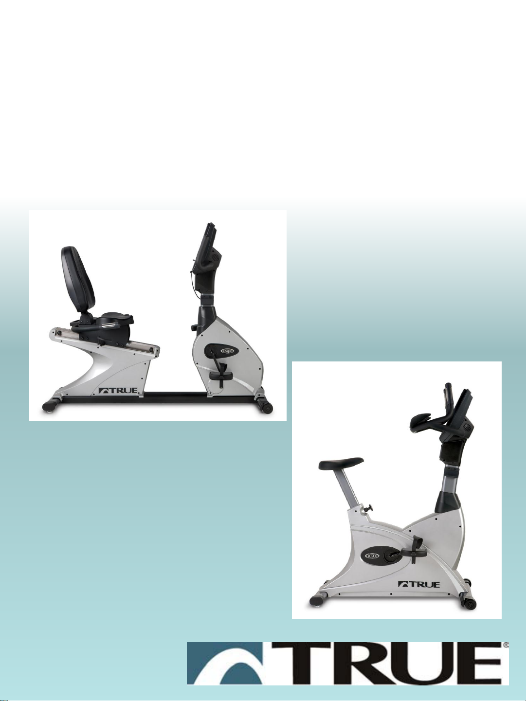
Troubleshooting
CS800/LC900
Bikes
Page 2
CS800/900LC Bike
Troubleshooting
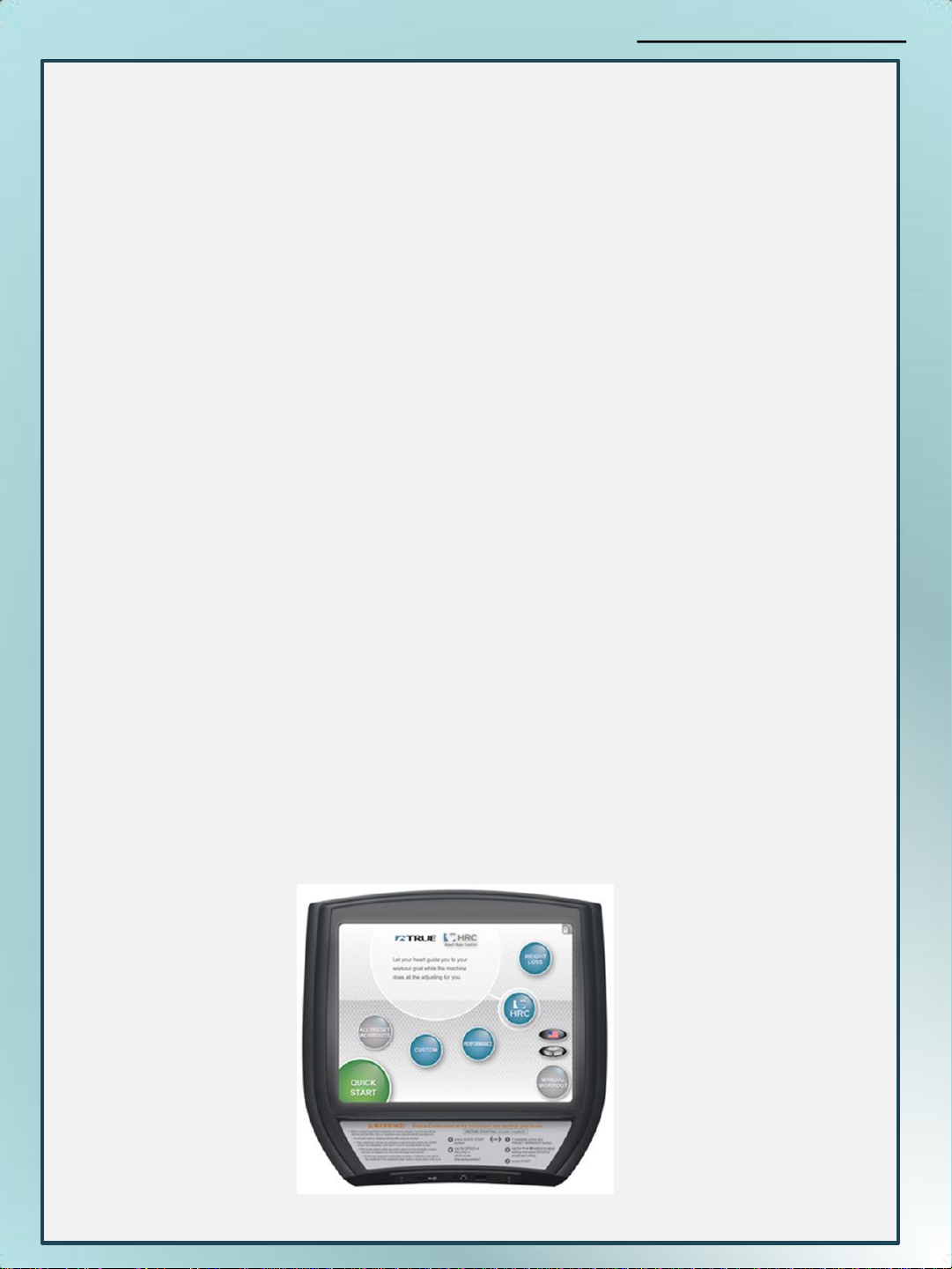
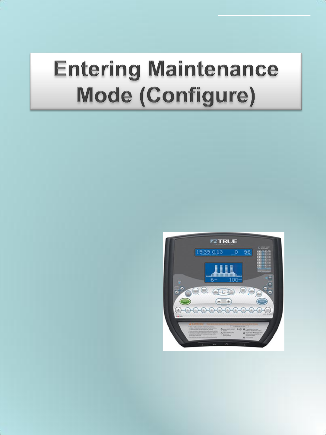
Entering the Maintenance Mode
15” Touch Screen:
The Maintenance Mode is designed to help the tech determine
certain faults in the upper control boards and feedback from
the brake system.
Press and hold the top left corner of screen until the True emblem
will begin to flash after 4 seconds.
Press and hold Manual Workout Button to reveal list of options
1. Configure (Displays the current model setup)
2. Calibration (Primary use on treadmills, can see RPM here)
3. Diagnostics (Used only on treadmills)
4. Production Tests (Test the brake system)
5. Utilities (Install software, TV tuner setup, touch screen setup)
2
Page 3
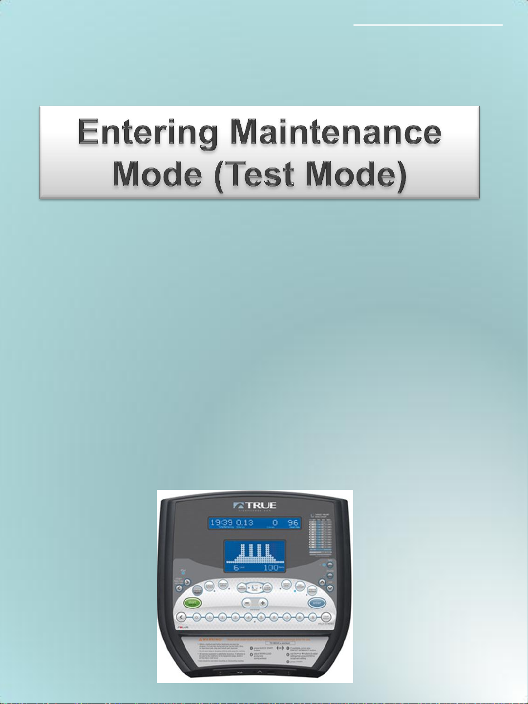
CS800/LC900 Bike
CS800, LC900 Bike Self Generating
(Electromagnetic Brake) LCD 2 Window
Press the CLEAR ENTRY button until the display blinks then
immediately press and hold the ENTER button until ENTER
PASSCODE appears.
Press 20173 then ENTER. The word Production Test will appear.
Pressing the enter button will scroll through a menu of items and
are as follows.
EPROM Test. (Shows SW Version)
Key Test (Test Keys)
Display Test (Test Display)
Control Test (Not Used By Service)
HR Test (Check Polar/Contact)
Vart Test (Not Used By Service)
A/D Channels (Not Used By Service)
Brake Pedal RPM (RPM Read from brake voltage)
Watch Dog Test (Exits Production Test)
BV Set Up (Program Entertainment) See Instructions.
Page 4
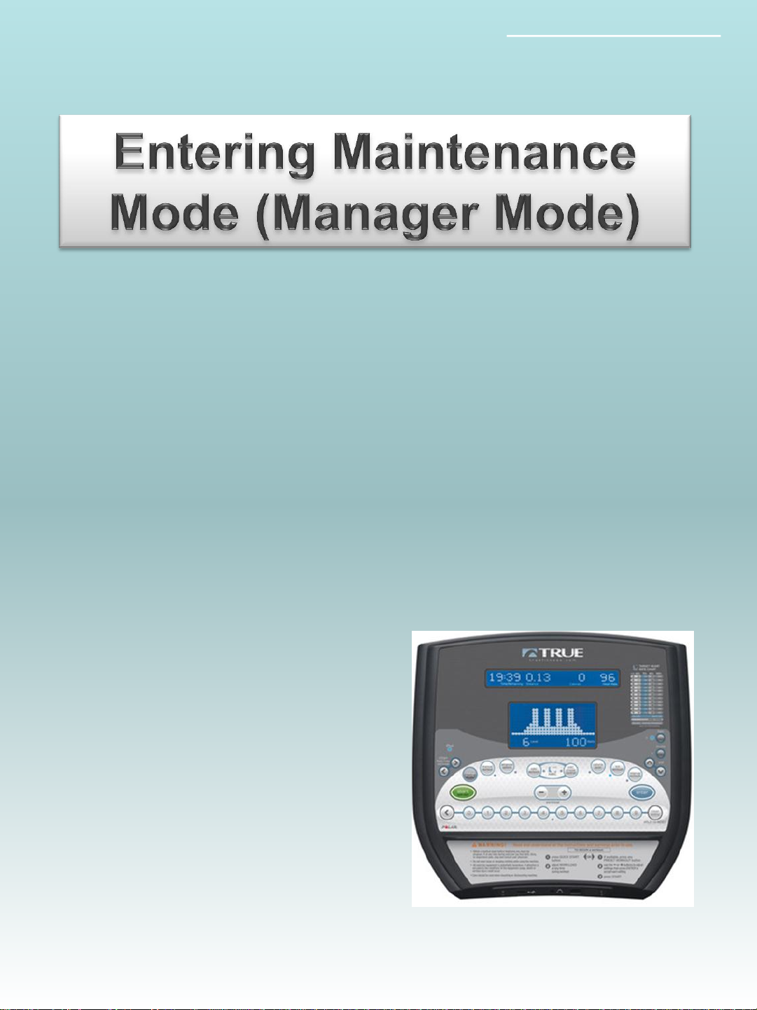
CS800/LC900 Bike
CS800, LC900 Bike Self Generating
(Electromagnetic Brake) LCD 2 Window
Manager Mode: 10101
Press the CLEAR ENTRY button until the display blinks then
immediately press and hold the ENTER button until ENTER
PASSCODE appears.
Press 10101 then ENTER. The word configure will appear.
Pressing the enter button will scroll through a menu of items and are
as follows.
Language (English, Spanish, German, French)
Units (English, Metric)
Max Time (45)
Default Time (30)
Pause Time (15 Sec)
Pulse Priority (Contact)
Operation Mode (Normal)
Man Operation (Mets)
Sound Enable (On/Off)
Smart Start Enable (On/Off)
Happy Mode (On/Off)
C Safe Enable (On/Off)
C Safe Auto (On/Off)
Default Weight (150)
Cal Slope (0.6666)
Cal Offset (0.0000)
Power Factor (1.0000)
Massage Backlight (15)
Matrix Backlight (32)
Message Contrast (35)
Matrix Contrast (45)
Factory Defaults (Off)
4
Page 5
CS800/LC900 Bike
CS800, LC900 Bike Self Generating
(Electromagnetic Brake) LCD 2 Window
Press the CLEAR ENTRY button until the display blinks then
immediately press and hold the ENTER button until ENTER
PASSCODE appears.
Press 48362 then ENTER. The word Production Test will appear.
Pressing the enter button will scroll through a menu of items and are
as follows.
Configure
Model
Gear Ratio
Language
Units
Max Time
Default Time
Pause Time
Pulse Priority
OP Mode
Man Operation
Sound
Smart Start
Happy Mode
C Safe Enable
C Safe Auto
Def Weight
Cal Slope
Cal Offset
Pwr Factor
Mess Backlight
Matrix Backlight
Factory Default
Page 6

CS800/LC900 Bike
Console
Display Will Not
Advance/Resets/ No
RPM Touch Screen
Upon starting any bike program, if the screen will not
advance, asks if you would like to end workout, RPM
signal is not being detected at the upper console, check
the following:
1. Starting from the console assembly check to make sure
the console data cable is plugged in firmly to the console
and into the lower board and check for
disconnections/cable damage in the pedestal neck.
2. If damage is found and cable has no continuity replace
cable. If cable tests good with a meter proceed to the next
step.
3. Check to make sure there is AC voltage at the lower board
from all three phases from the generator. The white cable
on the generator cable carries the RPM voltage.
4. If there is no AC voltage on the white cable check the
continuity of the cable. If there is no continuity replace the
generator cable. If there is continuity proceed to the next
step.
5. Check the voltage across all three phases of the generator.
If there is not voltage when the generator is moving across
all three phases replace the generator. If there is voltage
across 3 phases replace lower board.
6
Page 7
CS800/LC900 Bike
1. Disconnect the console data cable on the upper panel. If there is
2. Disconnect the console cable on the lower controller and retest for
3. If full resistance stops, replace the console cable.
4. If full resistance continues, disconnect the generator cable on the
Full Resistance
When Pedaling
Begins
still full resistance, continue to the next step. If the full resistance
condition subsides, replace upper console.
full resistance.
controller and retest for full resistance.
5. If full resistance stops, replace the controller.
6. If full resistance continues, disconnect the generator cable from the
generator assembly.
7. If full resistance stops, replace the generator cable.
8. If full resistance continues, replace the generator assembly.
7
Page 8

CS800/LC900 Bike
No Resistance
1. Leaving the console cable plugged into the upper console,
probe the console cable on pin 9 (Control Out) and pin 4 (GND)
for Volts DC. Press the workload up button (+) on the upper
console. Voltage should increase as resistance increases.
Check for same at the lower board also. (If there is voltage at
the upper and not the lower board replace the data cable)
2. If the voltage does not increase, replace the upper console.
3. If the voltage increases, check the coil cable for Volts DC on the
lower board, with the cable connected to the controller. Dig
through the glue and probe both cables. Voltage should
increase as resistance is increased.
4. If there is no increase in voltage at the controller, replace the
controller.
5. If there is a voltage increase at the controller, probe the coil
cable connector at the base of the generator for DC Volts.
Voltage should increase as resistance command increases.
Note: You must leave the coil cable connected and probe the
back of the connector to get an accurate reading.
6. If there is no voltage increase at the coil cable connector,
replace the coil cable.
7. If there is voltage increase at the coil cable connector, replace
the generator assembly.
8
Page 9

CS800/900LC Bike
No Console
Display Touch
Screen
The touch screen console requires a DC power supply to
operate. follow the steps below to determine the component
issue.
1. Disconnect the 2 conductor power cable (red and black) at the
upper board and probe for 12 VDC
2. If you test 12 VDC at the upper, replace the console.
3. If there is not 12 VDC at the upper probe for 12 VDC at the
power supply under shroud.
4. If there is 12 VDC at the power supply replace the intermediate
power cable.
5. If there is no 12 VDC, check for 120 VAC coming in to the
power supply. If there is 120 VAC replace the power supply.
9
Page 10

CS800/LC900 Bike
No Power/Console
Display Not
Powering Up 2
Window Display
1. Disconnect the console cable from the upper console.
2. Check for 12 VDC on pins 1 (+12V), and 4 (GND), and check for
12 VDC on pins 2 (+12V), and 4 (GND). 11 &12= 12v, 9 & 10=
gnd
3. If 12 VDC is found across both pins, replace the upper console.
4. If 12 VDC is not found, check for continuity on the console cable.
5. If there is no continuity, replace the console cable.
6. If there is continuity on the console cable, locate the VCON LED
and GEN+ LED on controller.
7. If GEN+ LED is illuminated when pedaling and the VCON LED is
not lit, replace the controller.
8. If GEN + LED is not illuminated, check for Volts AC from the
generator cable (black and white wires) connected to J1 on the
controller. The reading should be approximately 50-80 Volts AC
at slow speed.
10
Page 11

CS800/LC900 Bike
Warning
This True Fitness Technology Inc. equipment contains
hazardous voltages and high speed moving parts.
Contact with these hazards will potentially cause death,
serious personal injury or may damage equipment.
Only qualified personnel, (as outlined below), should
install, operate and maintain this equipment. Always
properly ground equipment and lock out electric power,
(de-energize), before maintenance, (unless instructed to
power equipment as part of a test procedure or an
electrical check). True recommends the use of safety
glasses when servicing equipment.
Using non-specified / unauthorized parts or components
to repair equipment, or tampering with safety
devices/systems will result in dangerous conditions which
can potentially cause damage to equipment, severe
personal injury or death. Take note of and follow all safety
instructions contained in this manual.
9. If there is voltage on the generator cable, replace the
controller.
10. If there is no voltage on the generator cable, test for continuity
on the generator cable.
11. If the continuity test fails on the generator cable, replace the
generator cable.
12. If the generator cable has continuity, replace the generator
assembly.
TrueFitness.com
11
Page 12

CS800/LC900 Bike
I pod will not
connect
Remove the 2 Philips screws that attach the I Pod
plate to the console.
12
Page 13

I pod will not
connect
Unplug all of the cables that are attached to the
I pod Faceplate.
CS800/LC900 Bike
13
Page 14

I pod will not
connect
Remove the I Pod cable from faceplate and unplug
from the console. Replace new cable in reverse
order. Reinstall the faceplate.
CS800/LC900 Bike
14
Page 15

CS800/LC900 Bike
Headphone Jack
Has Static/No
Sound
In the event that the headphones when plugged in to
The console create static, intermittent sound, or no
Sound at all replace the headphone jack according
to the procedure below.
Remove the 2 Philips screws that attach the I Pod plate
to the console.
15
Page 16

CS800/LC900 Bike
Headphone Jack
Has Static/No
Sound
Unplug all of the cables that are attached to the I pod
Faceplate.
16
Page 17

CS800/LC900 Bike
Headphone Jack
Has Static/No
Sound
Remove the 2 Phillips screws that attach the headphone
jack to the I pod plate.
Install the new headphone jack and test
17
Page 18

LCD 2 Window Displays
Software Installation Instructions for the
Bike 2 Window LCD Displays
First check and record the current software version by pressing and
holding the CLEAR ENTRY button while pedaling. When the screen
blanks out press and hold ENTER until enter code appears, Press
20173 then press ENTER and then START to display the software
version.
Insert the USB Storage Device into the console.
Press and hold Clear/Entry while pedaling until screen blanks out.
Immediately press and hold the channel up/FWD button until code
update appears on screen.
Press Enter and the software will upload to the console
When screen returns to normal mode remove the USB Storage
Device from the console and verify the new software uploaded in the
unit.
Page 19

Broadcastvision TV Preset Programming Instructions
2 Window Display for TRUE FITNESS Treadmills and Bikes
NOTES:
Bikes Only: Because this is a self-generating product, you must
continue to pedal during this procedure.
Treadmills: Plug in treadmill and flip power switch ON.
Text messages shown on display are indicated below in “QUOTATION
MARKS”.
Key names are indicated below in BOLD CAPS.
Broadcastvision is abbreviated BV below.
TV Programming
1.Note the number of TV’s visible in the facility room that you intend to
program audio setup for.
►ENTERING TEST MODE (NOTE: STEPS 1 – 4 are time dependent.
Press keys quickly)
Step 2. Press and hold the CLEAR ENTRY key until display blanks, then
quickly proceed to STEP 3.
Step 3. Press and hold the ENTER key until you hear a beep, then
quickly proceed to STEP 4.
“PASS CODE” will display.
Step 4. Press the following number keys in sequence 2 0 1 7 3 and press
the ENTER key.
“CONSOLE VERSION” will display.
►ENTERING BV SETUP MODE
1.Press the ENTER key repeatedly until “BV SETUP” is displayed.
2.Press the START key on center pod to enter BV SETUP mode.
“ENTER PROG MODE” will display.
3.Press the 2 key to select BV Series 2.
“LOAD BV SERIES 2” will display.
NOTE: These Displays are optimally designed to work with
Broadcastvision transmitters which should be part of this wireless
installation. If non-Broadcastvision transmitters are being used, one
should try at this point of these instructions to press 4 to LOAD BV
SERIES 4 for Mye®/ Fantaay® transmitters or press 8 to LOAD BV
SERIES 8 for Cardio Theater® LCS transmitters or press 9 to LOAD BV
SERIES 9 for Cardio Theater® xTV transmitters. This may allow for
reception under these circumstances.
Page 20

►PROGRAMMING TV PRESET CHANNEL LOCATIONS
Plug stereo headphones into console and wear
headphones for remaining steps of TV Programming.
Programming the first preset channel
If you clearly hear the TV audio that want to program in the
first preset channel location, then press the MUTE key
to save it.
“SAVE FREQ TO CHAN” will display.
If you do not hear the TV audio that you want, press the
VOL Λ key to select the desired TV transmitter audio,
and then press the MUTE key to save it.
NOTE: The order in which TV transmitter audio channels are
saved determines their displayed TV channel number when in
normal display mode. The first TV transmitter audio channel
saved will become “TV CHAN 1”, and the next TV transmitter
audio channel saved will become “TV CHAN 2”, etc.
►PROGRAMMING THE NEXT TV PRESET CHANNEL (and
remaining channels)
Repeatedly press the VOL Λ key until you hear the TV audio that
you want to program, and then press the MUTE key to save it.
Use this same procedure to program all other preset channel
locations for all remaining visible TV’s.
If you accidently save TV audio to the wrong preset channel
location, press the SOURCE key to unsave it. “UNSAVE
FREQ IN CH” will display. Then repeat STEP 9 for desired TV
audio source.
To exit programming mode, Press and hold the CLEAR ENTRY
key until display blanks and resets to normal operate mode.
TV Programming is now complete.
Should you need technical assistance for your TRUE Fitness product contact TRUE Fitness Technical Support at 1-800-883-8783
Page 21

Software Installation for Touch Screen
21
Page 22

Software Installation for Touch Screen
22
Page 23

Software Installation for Touch Screen
23
 Loading...