

Page 1
Operator’s Manual
SAFETY INFORMATION
• SAFETY ALERT SYMBOLS •
Safety alert symbols are used to draw your attention to possible dangers. These symbols, and their
explanations, deserve your careful attention and understanding. The safety warnings do not by
themselves eliminate any danger. The instructions or warnings they give are not substitutes for
proper accident prevention measures. These safety instructions are not meant to cover every
possible condition that may occur. If questions arise, please call the Customer Support
Department at 1-800-828-5500 (U.S.) or 1-800-668-1238 (Canada).
SYMBOL MEANING
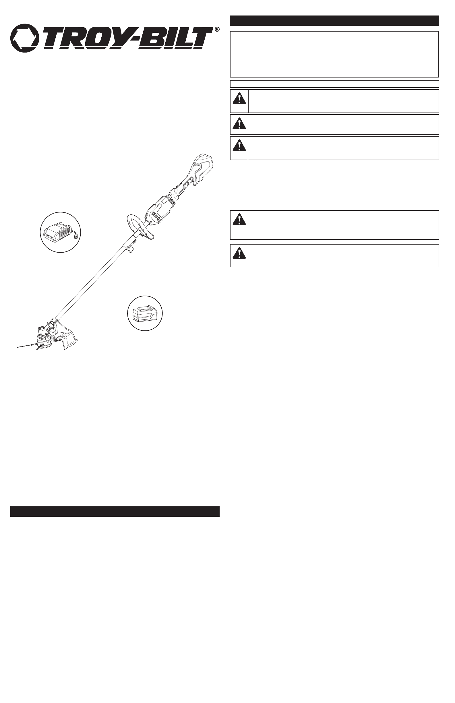
Battery-Powered Trimmer
TOOLS REQUIRED:
• #2 Phillips screwdriver
• 3/8” Socket
20 Volt Lithium-Ion
TB60AF
DANGER:
Failure to obey a safety DANGER signal WILL result in serious injury or death to yourself or
to others.
WARNING:
Failure to obey a safety WARNING signal CAN result in serious injury to yourself or to others.
Signals an EXTREME hazard.
Signals a SERIOUS hazard.
CAUTION:Signals a MODERATE hazard.
Failure to obey a safety CAUTION signal MAY result in property damage or injury to
yourself or to others.
IMPORTANT! Signals special mechanical information.
NOTE: Signals additional important general information.
• IMPORTANT SAFETY INSTRUCTIONS •
ALIFORNIA PROPOSITION 65
C
WARNING:Battery posts, terminals and certain finished components contain
lead, lead compounds and chemicals known to the State of California to cause cancer and
birth defects or other reproductive harm. Wash hands after handling.
WARNING:
always be followed to reduce the risk of fire, electric shock and injury to persons, including
the following.
When using an electric unit, basic safety precautions should
Use 20V Lithium-Ion Battery TB20V or TB20V50 (TB20V not included)
Use 20V Lithium-Ion Battery Charger TBCHGR
TABLE OF CONTENTS
Service Information . . . . . . . . . . . . . . . . . . . . . . . . . . . . . . . . . . . . . . . . . . . . . . . . . . . . . . . . . . . . . .1
Safety Information . . . . . . . . . . . . . . . . . . . . . . . . . . . . . . . . . . . . . . . . . . . . . . . . . . . . . . . . . . . . . . .1
Know Your Unit . . . . . . . . . . . . . . . . . . . . . . . . . . . . . . . . . . . . . . . . . . . . . . . . . . . . . . . . . . . . . . . . .3
Assembly Instructions . . . . . . . . . . . . . . . . . . . . . . . . . . . . . . . . . . . . . . . . . . . . . . . . . . . . . . . . . . . .3
Starting and Stopping Instructions . . . . . . . . . . . . . . . . . . . . . . . . . . . . . . . . . . . . . . . . . . . . . . . . . .4
Operating Instructions . . . . . . . . . . . . . . . . . . . . . . . . . . . . . . . . . . . . . . . . . . . . . . . . . . . . . . . . . . .4
Maintenance and Repair Instructions . . . . . . . . . . . . . . . . . . . . . . . . . . . . . . . . . . . . . . . . . . . . . . . .5
Cleaning and Storage . . . . . . . . . . . . . . . . . . . . . . . . . . . . . . . . . . . . . . . . . . . . . . . . . . . . . . . . . . . .5
Troubleshooting . . . . . . . . . . . . . . . . . . . . . . . . . . . . . . . . . . . . . . . . . . . . . . . . . . . . . . . . . . . . . . . .5
Specifications . . . . . . . . . . . . . . . . . . . . . . . . . . . . . . . . . . . . . . . . . . . . . . . . . . . . . . . . . . . . . . . . . .5
Warranty Information . . . . . . . . . . . . . . . . . . . . . . . . . . . . . . . . . . . . . . . . . . . . . . . . . . . . . . . . . . .16
All information, illustrations and specifications in this manual are based on the latest product information
available at the time of printing. We reserve the right to make changes at any time without notice.
Copyright© 2011 MTD SOUTHWEST INC, All Rights Reserved.
SAVE THESE INSTRUCTIONS
SERVICE INFORMATION
DO NOT RETURN THIS UNIT TO THE RETAILER. PROOF OF PURCHASE WILL BE REQUIRED FOR
WARRANTY SERVICE.
For assistance regarding the assembly, controls, operation or maintenance of the unit, please call the
Customer Support Department: 1-800-828-5500 (U.S.) or 1-800-668-1238 (Canada).
Additional information about the unit can be found on our website: www.troybilt.com (U.S.) or
www.troybilt.ca (Canada).
Please call the Customer Support Department for replacement parts. When servicing, use only identical
replacement parts.
READ ALL INSTRUCTIONS BEFORE OPERATING
BASIC SAFETY PRECAUTIONS
• DO NOT rely exclusively upon the safety devices built into the unit.
• DO NOT allow the unit to be used as a toy.
• Please read the entire operator’s manual carefully before attempting to assemble, operate or
maintain the unit.
• Follow all safety instructions. Failure to do so can result in property damage or serious injury to
yourself and/or others.
• Be thoroughly familiar with the controls and the proper use of the unit. Know how to stop the unit
and disengage the controls quickly.
• Stay alert! Do not operate the unit when tired, ill or under the influence of alcohol, drugs or medication.
• Never allow children to operate the unit. Never allow adults to operate the unit without proper instruction.
• Make sure that all guards and safety attachments are properly installed before operating the unit.
• Keep these instructions. Refer to them often and use them to instruct other users. If loaning
someone this unit, also loan them these instructions.
• Keep bystanders, especially children and pets, at least 50 feet (15 m) away. If anyone enters the
work area, stop the unit!
• Keep the work area clean. Cluttered areas invite injuries. Do not start the operation until the work
area is clear and free from obstructions and there is secure footing.
• Always wear appropriate eye and ear protection when operating this unit. Wear safety goggles, or
safety glasses with side shields, that are marked as meeting ANSI Z87.1-1989 standards. Failure
to do so could result in serious eye injury caused by thrown or falling objects. If the operation is
dusty, wear a face mask or dust mask.
• Dress appropriately. Wear non-slip protective gloves and boots. Do not wear loose clothing,
jewelry, short pants, sandals or go barefoot. Secure hair above shoulder level to prevent
entanglement in moving parts.
• Only use the unit in daylight or good artificial light.
• Only use the unit for its intended purpose. Only use the unit as described in this manual.
TRIMMER SAFETY PRECAUTIONS
• Inspect the work area before using the unit. Remove any hard and/or sharp objects, such as metal,
glass, wire, etc. If thrown, such objects could cause property damage or injury to the operator or
bystanders.
• Only use original equipment manufacturer replacement cutting blades. Never use metal-reinforced
line, wire or rope. These can break off and become dangerous projectiles.
• Keep the unit clean of vegetation and other materials that may become lodged between the
cutting head and shield. Keep vent openings clean and clear of debris.
• The cutting head shield must always be in place while operating the unit. Do not operate the unit
without the proper cutting blades installed.
• Extra caution is required when using the unit for edging purposes. There is an increased risk of
injury or property damage caused by thrown objects when the cutting head shield is not held
horizontal to the ground.
GENERAL SAFETY PRECAUTIONS
• DO NOT over reach.
• DO NOT operate the unit on unstable surfaces, such as in trees or on ladders, slopes or rooftops.
Be very careful when using the unit on stairs.
• DO NOT handle the unit with wet hands.
• DO NOT expose the unit to rain. Do not use the unit in damp or wet locations or conditions.
• DO NOT
• DO NOT use the unit in the presence of flammable liquids or gases.
• DO NOT operate a unit that is damaged, improperly adjusted or not completely and securely
assembled. Be sure that the unit stops when the trigger is released. Do not use the unit if the switch
does not turn the unit on and off properly or if the switch lock does not work.
• DO NOT attempt operations beyond the operator’s capacity or experience.
• DO NOT operate the unit with one hand! Serious injury to the operator, helpers or bystanders may result
from one-handed operation. This unit is intended for two-handed use. Grip the unit firmly with both
hands when the motor is running. Keep the left hand on the D-handle and the right hand on the shaft
grip. Use a firm grip with thumbs and fingers encircling the handles. Do not let go!
• DO NOT force the unit. It will do a better, safer job when used at the intended rate.
• Adjust the D-handle to provide the best grip.
• Keep proper footing and balance at all times.
• Keep hair, loose clothing, fingers and all other body parts away from moving parts. Do not try to touch or
stop moving parts when they rotate.
• To reduce the risk of electric shock, avoid body contact with grounded conductors, such as metal pipes
or wire fences.
• Always stop the motor when operation is delayed, before setting down the unit or when walking from
one location to another. Make sure the unit comes to a complete stop.
•
To avoid accidental starting, never carry the unit with fingers on the switch trigger. Always carry the unit by the
handles with the battery removed.
•
Always make sure the lock-off button is in the locked or OFF position before installing or removing the battery.
• If the unit strikes or becomes entangled with a foreign object, stop the motor immediately, remove
the battery and check for damage. Do not restart or operate the unit before repairing damage.
operate the unit on wet surfaces.
769-07272 P00 09/11
Page 2
SAFETY INFORMATION
• This unit is intended for infrequent use by homeowners. It is not intended for prolonged use.
ELECTRICAL SAFETY PRECAUTIONS
WARNING:
water for at least 15 minutes. Get immediate medical attention. Do not charge the battery
pack in the rain or in wet conditions. Do not immerse the unit, battery pack, or charger in
water or other liquid.
• A battery-operated tool with integral batteries or a separate battery pack must be recharged only
with the specified charger for the battery. A charger that may be suitable for one type of battery
may create a risk or fire when used with another battery.
• Use a battery-operated tool only with specific battery pack. Use of any other batteries may create
a risk of fire.
• When the battery is not installed in the unit, keep it away from paper clips, coins, keys, nails,
screws or other metal objects that could make a connection from one terminal to another. Shorting
the battery terminals together may cause sparks, burns or a fire.
Battery Pack and Charger Safety
If battery fluid gets in the eyes, flush immediately with clean
WARNING:The battery pack may develop a small leak under extreme usage
or temperature conditions. If the outer seal is broken and the leakage gets on skin:
- Use soap and water to wash the area immediately.
- Neutralize with lemon juice, vinegar or other mild acid.
And seek medical attention immediately.
• DO NOT probe the charger with conductive material. There is a risk of electric shock.
• DO NOT insert battery into the charger if the battery pack is cracked or damaged.
• DO NOT charge any batteries except the ones specified by the charger.
• DO NOT try to use the charger for any other purposes than what is presented in the operator’s manual.
• DO NOT charge batteries in the rain or in wet conditions. Keep the charger in a cool and dry area.
• Keep the charger away from all liquid.
• Do not allow the battery pack or charger to overheat. If they are warm, allow them to cool down.
Recharge only at room temperature; 32 and 86˚ F (0 and 30˚ C).
• Do not cover the ventilation slots on the charger. Do not place charger on a soft surface. Keep the
ventilation slots of the charger clean and clear of dirt and debris.
• Do not allow small metal items or material such as steel wool, aluminum foil or other foreign
particles into the charger cavity.
• Handle batteries with care. Do not short the battery with conductive materials, such as rings,
bracelets, keys, etc. Doing so may damage the battery or cause personal injury.
• Unplug the charger before cleaning and when not in use.
• Do not connect two chargers together.
• Do not place the charger where the power cord might be stepped on, tripped over, or subjected to
damage.
• An extension cord should not be used unless absolutely necessary. Use of an improper extension
cord could result in a risk of fire, electric shock or electrocution.
• DO NOT abuse the extension cord or the power cord on the unit. Never pull or carry the unit by
the cord(s), use the cord(s) as a handle, close a door on a cord, pull the cord(s) around sharp
edges or corners or yank the cord(s) to disconnect the unit. Grasp the plug(s), not the cord(s), to
disconnect the unit.
• DO NOT modify the power cord, extension cord, power cord plug, extension cord plug or wall
outlet in any way.
• DO NOT use multiple extension cords.
• Keep the cords away from oil, water, sharp objects and heated surfaces.
• Keep the cords away from the operator’s feet to prevent tripping.
• Make sure the cords are in good condition. Inspect the power cord and extension cord
periodically. Look closely for deterioration, cuts or cracks in the insulation. If the power cord is
damaged, have it repaired by an authorized service center. If the extension cord is damaged,
replace it. Do not use a damaged cord or plug.
• If the extension cord is damaged in any manner while plugged in, disconnect the extension cord
from the receptacle.
• If the extension is to be used outside, the cord must be suitable for outdoor use. Any cord marked
for outdoor use can also be used for indoor work. The letters “W” or “WA” on the cord jacket
indicate that the cord is suitable for outdoor use.
• Make sure the extension cord is heavy enough to carry the current drawn by the unit. An
undersized cord will cause a drop in line voltage resulting in loss of power and overheating. If in
doubt, use the next heavier gauge cord. The smaller the gauge number, the heavier the cord.
MINIMUM WIRE SIZE FOR EXTENSION CORDS
FOR 120 VOLT APPLIANCES USING 0-6 AMPS
Cord Length (feet) 25
Wire Size (AWG) 18
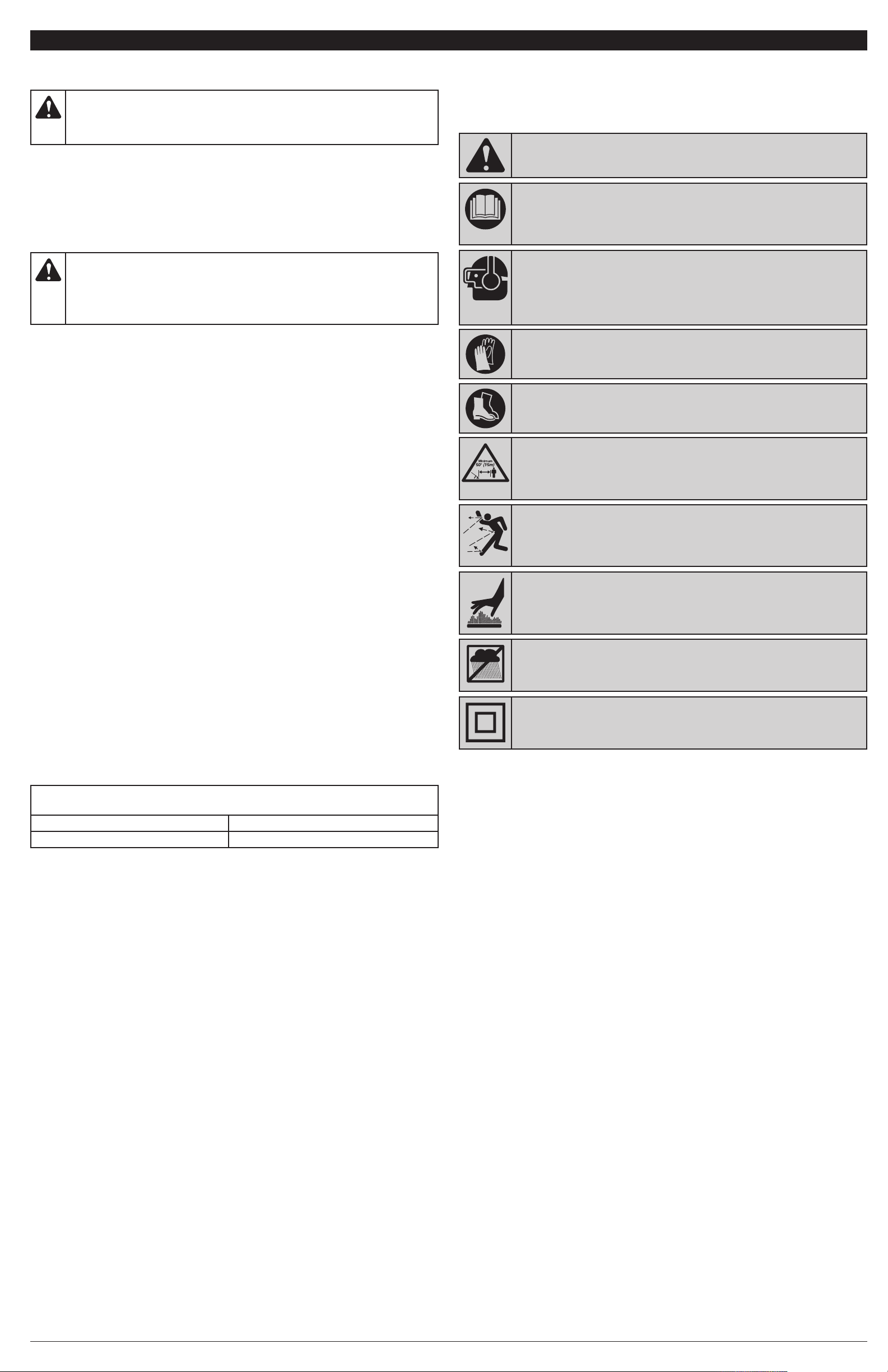
• SAFETY AND INTERNATIONAL SYMBOLS •
This operator's manual describes safety and international symbols and pictographs that
may appear on this product. Read the operator's manual for complete safety, assembly,
operating, maintenance and repair information.
SYMBOL MEANING
• SAFETY ALERT SYMBOL
Indicates danger, warning or caution. May be used in conjunction with other
symbols or pictographs.
• READ OPERATOR'S MANUAL
WARNING:R
nd safety instructions. Failure to do so can result in serious injury to the operator
a
ead the operator’s manual(s) and follow all warnings
and/or bystanders.
• WEAR EYE AND HEARING PROTECTION
WARNING:Thrown objects and loud noise can cause severe eye
injury and hearing loss. Wear eye protection meeting ANSI Z87.1-1989
standards and ear protection when operating this unit. Use a full face shield
when needed.
EAR SAFETY GLOVES
• W
Wear non-slip, heavy-duty protective gloves when handling the unit.
• WEAR SAFETY FOOTWEAR
Wear non-slip safety footwear when using this equipment.
• KEEP BYSTANDERS AWAY
WARNING:Keep all bystanders, especially children and pets, at
east 50 feet (15 m) from the operating area. If anyone enters the work area, stop
l
the unit!
• THROWN OBJECTS AND ROTATING CUTTER CAN CAUSE SEVERE
INJURY
WARNING: Small objects can be propelled at high speed,
causing injury. Keep away from the rotating cutter.
• HOT SURFACE
WARNING: Do not touch a hot surface. You may get burned.
These parts get extremely hot from operation. They remain hot for a short
time after the unit is turned off.
• DO NOT USE IN THE RAIN
WARNING:Avoid dangerous environments. Never operate your
unit in the rain or in damp or wet conditions. Moisture is a shock hazard.
• DOUBLE INSULATED
Two systems of insulation are provided instead of grounding. There is no
grounding provided and no means of grounding should be added to the unit.
SAVE THESE INSTRUCTIONS
• A nameplate on your unit indicates the voltage used. Never connect the unit to an AC voltage that
differs from this voltage.
• Ground Fault Circuit Interrupter (GFCI) protection should be provided on the circuit(s) or outlet(s) that
will be used with the unit. For an extra measure of safety, use receptacles with built-in GFCI protection.
MAINTENANCE AND STORAGE SAFETY
• DO NOT perform
attempt to repair; there are no user serviceable parts inside.
• If the unit is not working as it should, has been dropped, damaged, left outdoors or dropped into
water, do not use the unit.
• All service, other than the maintenance procedures described in this manual, should be performed
by an authorized service center.
• Follow all maintenance instructions in this manual.
• Before inspecting, servicing, cleaning, storing, transporting or replacing any parts on the unit:
1. Stop the motor. Make sure the lock-off button is in the locked or OFF position.
2.
Make sure all moving parts have stopped.
3. Remove the battery.
4. Allow the unit to cool.
• Never remove, modify or make inoperative any safety device furnished with the unit.
• Frequently inspect the unit for damage. Before further use, any damaged part should be carefully
checked to determine that it will operate properly and perform its intended function. Check for
alignment of moving parts, binding of moving parts, breakage of parts, fuel leaks and any other
conditions that may affect its operation. Damaged parts should be properly repaired or replaced by
an authorized service center, unless otherwise indicated in this manual.
• If the unit starts to vibrate abnormally, stop the motor, remove the battery and allow the unit to cool.
Then inspect the unit for the cause of the vibration. Vibration is generally an indicator of trouble.
• Use only original manufacturer replacement parts and accessories, which are designed specifically
to enhance the performance and maximize the safe operation of the product. Failure to do so may
cause poor performance and possible injury.
• Remove the battery from the unit when not in use.
• Be sure to secure the unit while transporting.
• When not in use, store the unit indoors in a locked-up and dry, or high and dry, place to prevent
unauthorized use or damage. Keep out of the reach of children.
• Keep the handles dry, clean and free from debris, oil and grease. Clean the unit after each use. Never
douse or spray the unit with water or any other liquid. Do not wash the unit with a hose; avoid getting
water in the motor and electrical connections. Do not use solvents or strong detergents.
maintenance
procedures other than those described in this manual. Do not
2
Page 3
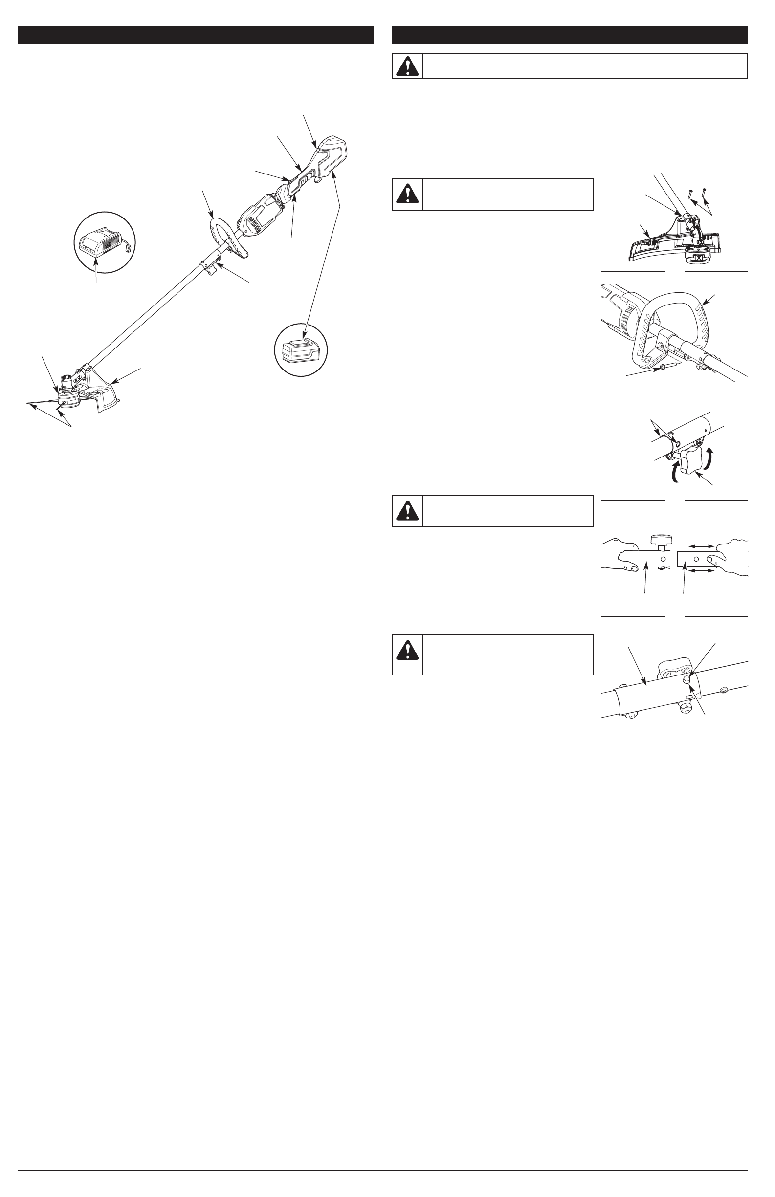
KNOW YOUR UNIT ASSEMBLY INSTRUCTIONS
APPLICATIONS
As a trimmer:
• Cutting grass and light weeds
• Edging
• Decorative trimming around trees, fences, etc.
TOOLS REQUIRED:
• #2 Phillips screwdriver
• 3/8” Socket
Battery Charger
utting Head
C
utting Head Shield
C
Cutting Blades
-Handle
D
ock-off
L
Button
haft Grip
S
EZ-Link™
Coupler
Handle
H
Switch
Trigger
ousing
B
attery
WARNING: Make sure the motor is off and the battery is disconnected before
assembling or disassembling any components.
This unit requires assembly.
UNPACKING
• Carefully remove the product and any accessories from the box.
• Inspect the product carefully to make sure no breakage or damage occurred during shipping.
• Do not discard the packing material until you have carefully inspected and satisfactorily operated
the product.
• If any parts are damaged or missing, please call 1-800-828-5500 (U.S.) or 1-800-668-1238
(Canada) for assistance.
INSTALLING THE CUTTING HEAD SHIELD
ount
WARNING: To prevent serious personal
injury, never operate the unit without the
cutting head shield in place.
Use the following instructions if the cutting head shield is
not installed. Use only the instructions that apply to the
type of shaft and shield equipped with this unit.
1. Place the cutting head shield onto the mount bracket.
Align the holes in the cutting head shield with the holes
in the mount bracket. (Fig. 1)
2. Screw the 2 screws through the mount bracket and into
the cutting head shield until finger tight.
3. Using a #2 Phillips screwdriver, tighten the screws until
the cutting head shield is firmly in place. Tighten the
screws equally. The gap between the mount bracket and
the cutting head shield should be the same on each side.
INSTALLING THE CUTTING BLADES
Refer to Cutting Blade Replacement/Installation in the
Maintenance and Repair Instructions section.
INSTALLING AND ADJUSTING THE D-HANDLE
Installing the D-handle
1. Push the D-handle down onto the boom (Fig. 2), so that
the bolt hole in the D-handle is to the right.
2. Insert the bolt into the hole in the handle. Do not tighten
the bolt completely until after adjusting the D-handle.
Adjusting the D-handle
1. Make sure the bolt is loose enough for the D-handle to
move along the boom.
2. While holding the unit in the operating position (Fig. 11),
move the D-handle to the location that provides the best
grip.
3. Tighten the bolt until the D-handle is secure. (Fig. 2)
OPERATING THE EZ-LINK SYSTEM
WARNING: To avoid serious personal injury
and damage to the unit, shut the unit off before
removing or installing add-ons.
M
Bracket
utting Head
C
Shield
Bolt
0˚ Edging Holes
9
(Trimmer Only)
ig. 1
F
ig. 2
F
Fig. 3
Screws (2)
D-Handle
Knob
NOTE: To make installing or removing the add-on easier,
place the unit on the ground or on a work bench.
Installing the Add-On
NOTE: Remove the protective cap and gray spacer from the
upper and lower shafts prior to assembling the add-on.
1. Turn the knob counterclockwise to loosen (Fig. 3).
2. While firmly holding the add-on, push it straight into the
EZ-Link coupler (Fig. 4) until the release button snaps
firmly into the primary hole (Fig. 5).
3. Turn the knob clockwise to tighten (Fig. 3).
CAUTION: Before operating this unit, be
pper Shaft
U
Housing
EZ-Link Coupler
ower Shaft
L
Housing
Fig. 4
Release Button
sure that the release button is fully snapped
into the primary hole (Fig. 5), and that the knob
(Fig. 3) is securely tightened.
For decorative edging with the trimmer attachment, lock
the release button into one of the 90° holes (Fig. 3).
Check Flex Shaft Engagement Prior to Using
1. Start the unit. Refer to Starting and Stopping Instructions.
2. Briefly engage and release the trigger.
3. Check that add-on is operating.
ig. 5
F
Primary Hole
4. If the add-on is not operating, remove the add-on and repeat the steps for installing the add-on.
5. Recheck the operation of the add-on attachment.
NOTE: The blades are NOT installed on this product when first removed from packageing. Refer to
Trimmer Blade Replacement/Installation.
Removing the Add-On
1. Turn the knob counterclockwise to loosen (Fig. 3).
2. Press and hold the release button (Fig. 5).
3. While firmly holding the upper shaft housing, pull the add-on out of the EZ-Link coupler (Fig. 4).
3
Page 4
ASSEMBLY INSTRUCTIONS
OPERATING INSTRUCTIONS
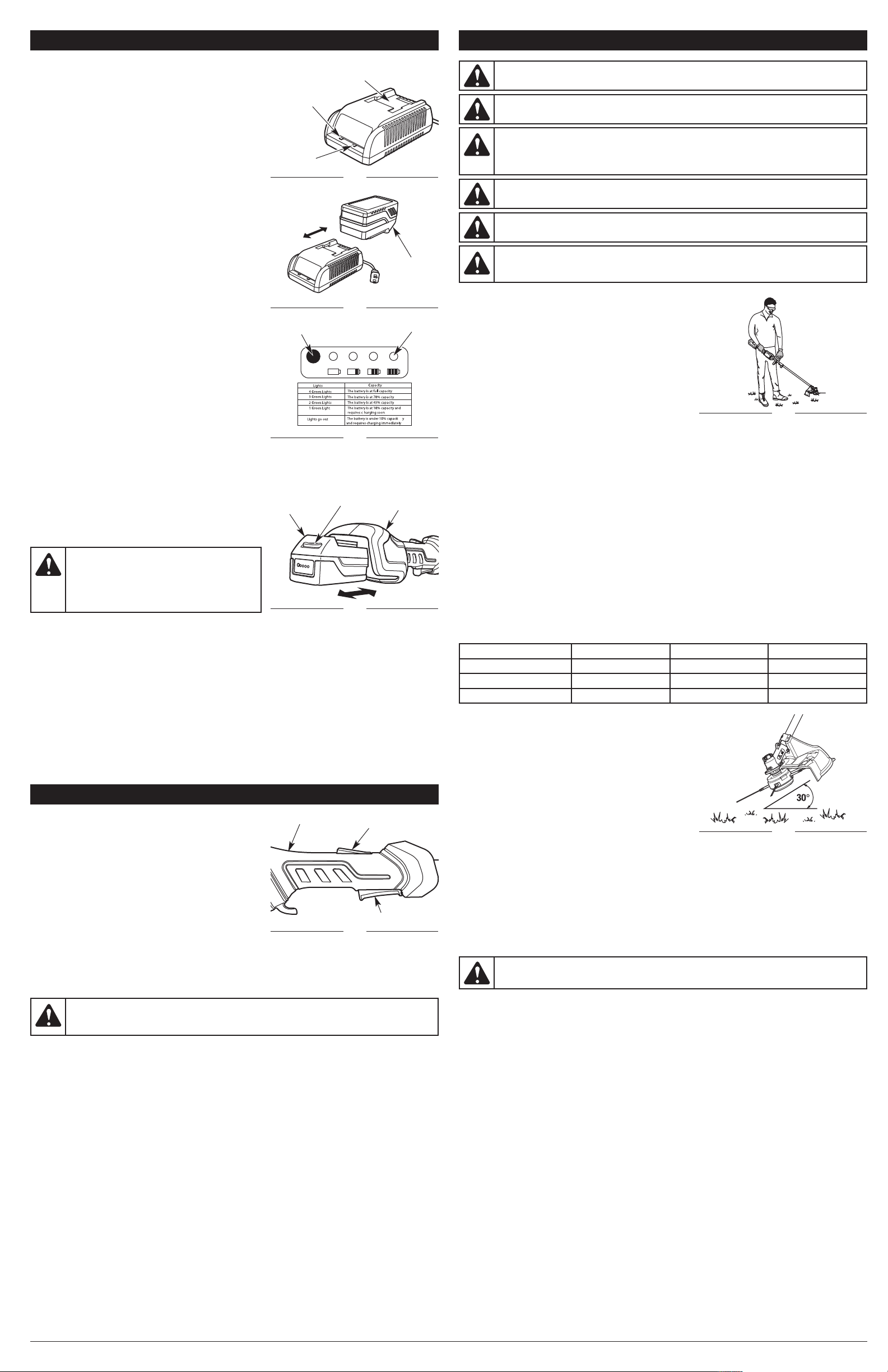
CHARGING THE BATTERY
NOTE: The battery is not shipped fully charged. It is
Battery
ompartment
C
recommended to fully charge the battery before use to
ensure that maximum run time can be achieved. The
lithium-ion battery will not develop a memory and may
be charged at any time. A fully discharged battery will
P
ower
LED
require approximately 1-2 hours to completely charge.
1. Plug the charger into an AC wall outlet/receptacle.
2. The red Power LED will illuminate (Fig. 6).
3. Insert the battery into the charger (Fig. 7).
NOTE: Make sure the battery is fully inserted into the
charge by making sure the red Indicator LED charge
Indicator
LED
ig. 6
F
light is on (Fig. 6).
4. Once the battery has reached a full charge level the
Indicator LED will turn from red to green (Fig. 6).
5. The battery may be removed or stored in the charger
once it is fully charged; however, it is recommended to
disconnect the plug from the wall outlet/receptacle. To
remove the battery, hold down the battery latch and
attery Latch
slide the battery off the charger (Fig. 7).
B
NOTE: Lithium-ion batteries, while in use, will continue to
provide full power without power fade unlike typical
batteries; when the battery is fully discharged, the
battery circuitry will immediately cut power to the tool
and require immediate charging.
Battery Instructions
CI Button
B
ig. 7
F
ED Meter
L
Press the battery capacity indicator (BCI) button. The lights will
illuminate according to the battery’s current power level (Fig. 8).
INSTALLING AND REMOVING THE BATTERY
Follow these instructions in order to avoid injury and to
reduce the risk of electric shock or fire:
• Verify that the lock-off button is in the locked or OFF
position before installing or removing the battery. Refer
to Starting and Stopping Instructions.
• Verify that the battery is removed and the lock-off button is
in the locked or OFF position before inspecting, adjusting
or performing maintenance on any part of the unit.
Fig. 8
Installing the Battery
1. Align the tongue of the battery with the handle cavity (Fig. 9).
2. Grasp the rear handle firmly.
3. Push the battery into the handle cavity until the latch
locks into place.
4. Do not use force when inserting the battery. It should
Battery
Battery Latch
Handle
ousing
H
slide into position and “click.”
Removing the Battery
CAUTION: When the battery is not installed
in the unit, keep it away from paper clips, coins,
keys, nails, screws or other metal objects that
could make a connection from one terminal to
another. Shorting the battery terminals together
may cause sparks, burns or a fire.
Fig. 9
1. Press the latch button on the battery down and hold (Fig. 9).
2. Grasp the rear handle firmly and pull the battery out of the handle cavity.
NOTE: The battery fits into the handle cavity snugly in order to prevent accidental dislodging. It may
require a strong pull to remove it.
IMPORTANT! The battery is equipped with an internal circuit breaker that will automatically shut off
power to the unit if the battery is overloaded during heavy use. Once cooled, the battery will reset
itself. Follow these steps if an overload occurs:
1. Release the switch trigger and then restart the unit. Refer to Starting and Stopping Instructions.
2. The battery may need to be removed for approximately 1 minute, allowed to cool and then reinstalled.
STARTING AND STOPPING INSTRUCTIONS
STARTING THE MOTOR
Make sure the immediate area is clear of any objects or
obstructions that could come in contact with the cutting head.
To help prevent accidental start-ups, this unit has a lock-off
button and switch trigger that must be used together to
start the unit.
1. Fit the battery into the handle cavity (Fig. 9). Refer to
Installing the Battery.
2. Press and hold the lock-off button (Fig. 10). This makes
the switch trigger operational.
3. While holding the lock-off button, press and hold the
switch trigger (Fig. 10).
4. Release the lock-off button and continue to squeeze the switch trigger for continued operation.
STOPPING THE MOTOR
1. Release the switch trigger.
NOTE: Upon release of the switch trigger, the lock-off button will automatically reset to the locked position.
Shaft Grip
Lock-off Button
Switch Trigger
Fig. 10
CAUTION: Always allow 5 seconds or more for the cutting head to come to a complete
stop after releasing the switch trigger. Do not invert the unit, or place any body parts near
the cutting head until it has come to a complete stop.
WARNING: Do not allow familiarity with this unit to promote carelessness. Remember
that a careless fraction of a second is enough to inflict serious injury.
WARNING: If any parts are damaged or missing, do not operate the unit until the parts
are replaced. Failure to heed this warning could result in serious personal injury.
WARNING: Always wear appropriate eye and ear protection when operating this unit.
Wear safety goggles, or safety glasses with side shields, that are marked as meeting ANSI
Z87.1-1989 standards. Failure to do so could result in serious eye injury caused by thrown
objects. If the operation is dusty, wear a face mask or dust mask.
WARNING: Wear non-slip gloves for maximum grip and protection. Refer to the Safety
Information section for appropriate safety equipment.
WARNING: Do not expose the unit to rain. Do not use the unit in damp or wet locations
or conditions.
ARNING:
W
To avoid serious injury, do not wear loose fitting garments, such as scarves,
strings, chains or ties, which could be drawn into the air intake. Long hair must be pulled
back and secured at the shoulders and neck.
PROPER GRIP ON HANDLE
• Always maintain a proper grip on the handles whenever
the motor is running. Grip the unit firmly with both
hands. Keep the left hand on the D-handle and the right
hand on the shaft grip. The fingers should encircle the
handle(s) and the thumb(s) should wrap under the
handle(s). The left arm should be straight and the right
arm slightly bent.
PROPER STANCE
• Balance body weight securely, with both feet on solid
ground.
WORK AREA PRECAUTIONS
Fig. 11
• Keep everyone – helpers, bystanders, children and animals – at least 50 feet (15 m) away from the
work area. If anyone enters the work area, stop the unit!
• Only operate the unit when visibility and light are adequate to see clearly.
• Remove stones, nails, glass and wire from the area before operating the unit.
• Only operate the unit during reasonable hours. Comply with times listed in local ordinances.
OPERATING THE TRIMMER
1. Hold the unit at waist level with the cutting head parallel to the ground so that it easily contacts the
grass without the need to bend over (Fig. 11).
2. Start the motor. Refer to Starting and Stopping Instructions.
3. Slowly move the cutting head into and out of the cutting area at the desired height.
• Move either in a forward-backward or side-to-side motion. When cutting from side-to-side, cut
from left to right whenever possible. This improves the unit’s cutting efficiency and directs
clippings away from the operator.
• Cutting shorter lengths produces the best results.
• Cut grass over 8 inches (200 mm) by working from top to bottom in small increments to avoid
premature blade wear or motor drag.
• Do not force the cutting head. Allow the tip of the blade to do the cutting, especially along
walls. Cutting with more than the tip will reduce cutting efficiency and may overload the motor.
• Use the throttle speed(s) recommended for the Vegetation Task, as listed below:
Vegetation Task Low Throttle Medium Throttle High Throttle
Edging
Trimming
Yes Yes No
No Yes Yes
Trimming against fences Yes Yes No
• Only trim when grass or weeds are dry.
4. Dispose of debris appropriately.
Decorative Trimming
Decorative trimming is the act of removing all vegetation
from around trees, posts, fences, etc. To accomplish it,
rotate the whole unit so that the cutting head is at a 30˚
angle to the ground (Fig. 12).
Cutting Blades
The cutting blades wear down and becomes shorter with
use. The life of the cutting blades is dependent upon:
• Following the trimming techniques previously
explained
Fig. 12
• What vegetation is cut
• Where the vegetation is cut.
For example, the cutting blades will wear faster when trimming against a foundation wall as opposed
to trimming around a tree.
Some blade breakage may occur from:
• Entanglement with foreign matter
• Normal blade fatigue
• Attempting to cut thick or stalky weeds
• Forcing the blades into objects such as walls or fence posts
WARNING: If blade breakage occurs, replace all blades immediately, as the unit may
become unstable and difficult to control, resulting in personal injury.
NOTE: Replace all cutting blades when the cutting performance becomes poor.
4
Page 5
MAINTENANCE AND REPAIR INSTRUCTIONS
CLEANING AND STORAGE
WARNING: Before inspecting, cleaning, or
servicing the unit, stop the motor, wait for all
moving parts to stop and remove the battery.
Failure to follow these instructions can result in
serious personal injury or property damage.
Cutting
ead
H
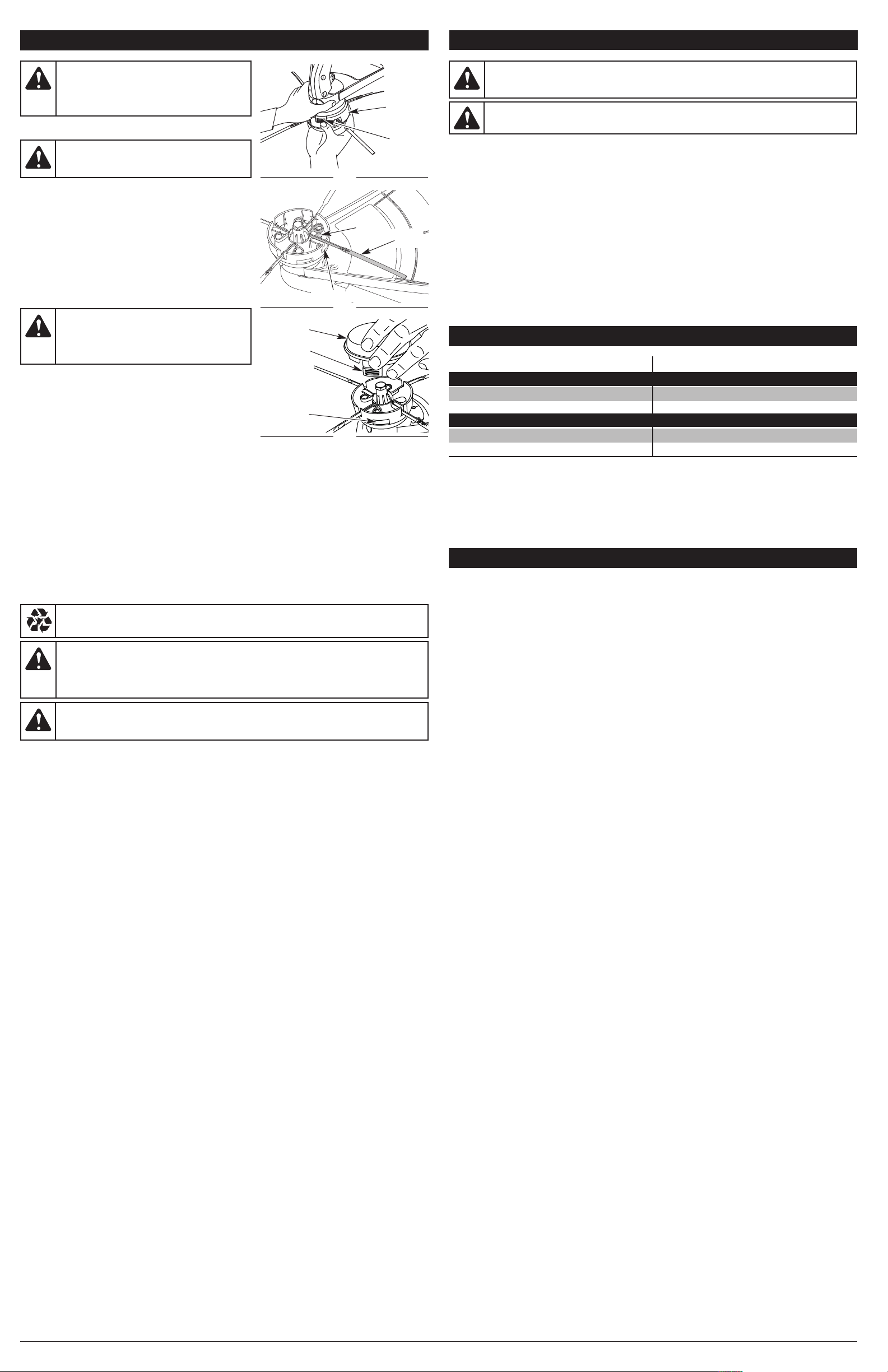
CUTTING BLADE REPLACEMENT/INSTALLATION
Cap Tab
WARNING: Never use metal-reinforced line,
wire, chain or rope. These can break off and
become dangerous projectiles.
F
ig. 13
Always use original equipment manufacturer replacement
blades. Blades other than those specified may make the motor
overheat or fail. This unit uses four (4) green cutting blades.
Removing the Cutting Blades
1. Remove the cutting head cap by pressing in on both
cap tabs and then pulling down on the cap. (Fig. 13)
eg
P
Cutting
Blade
2. Turn the cutting head over and grab an individual blade
near the cutting head and wiggle it up and down until
blade comes loose. (Fig. 14)
3. Repeat step 2 until all blades are removed.
Installing the Cutting Blades
Blade Slot
ig. 14
F
WARNING: Always install an even number
of blades (2 or 4). NEVER install an uneven
number of blades (1 or 3) as this will make the
unit unstable and hard to control, which could
result in serious personal injury.
4. Take the new blade so that the loop at the end is facing
away and to the right. (Fig. 14)
5. Place the loop onto the peg and adjust it so that it fits
into the slot on the cutting head. (Fig. 14)
6. Press down on the loop end of the blade till it is securely
in place.
7. Repeat steps 4 thru 6 until all 4 blades are in place. (Fig. 14)
8. Replace the cutting head cap, making sure to align the cap tabs with the cutting head tab slots.
(Fig. 15)
CHARGER MAINTENANCE
• Keep the charger clean and clear of debris. Do not allow foreign material into the recessed cavity
or on the contacts.
• Wipe with a dry cloth. Do not use solvents, water or place in wet conditions.
• Always unplug the charger when not in use.
• The battery pack may be stored in the charger. However, it is recommended to disconnect the
charger from the power source.
• To ensure safety and reliability, all repairs should be performed by a qualified service technician.
• Check that the charger contacts have not been shorted by debris or foreign material.
• Keep the charger and battery pack in an area that is between 65 and 75˚ F (18 and 24˚ C).
ENVIRONMENTALLY SAFE BATTERY DISPOSAL
The following toxic and corrosive materials are used in this units battery pack:
LITHIUM-ION, a toxic material.
ARNING:
W
All toxic materials must be disposed of in a specified manner to prevent
contamination of the environment. Before disposing of damaged or worn out lithium-ion
battery packs, contact your local waste disposal agency for information and specific
instructions. Take batteries to a local recycling and or disposal center, certified for lithiumion battery disposal.
Cap
Cap Tab
Cutting Head
Tab Slots
Fig. 15
WARNING: Do not use the battery pack if there are cracks or if it breaks, regardless if
there is leakage or not. Replace with a new battery pack. DO NOT ATTEMPT TO REPAIR!
As this may cause severe personal injury due to explosion or electrical shock.
WARNING: Do not let brake fluids, gasoline, petroleum-based products, penetrating oils,
etc., come in contact with plastic parts. These chemicals may damage, weaken and
destroy plastic, which may result in serious personal injury.
WARNING: To avoid risk of fire, electric shock or electrocution: DO NOT use a damp
cloth or detergent on the battery or battery charger. Wipe the outside with a dry, soft cloth.
CLEANING INSTRUCTIONS
1. Stop the motor and wait for all moving parts to stop.
2. Remove the battery from the unit.
3. Wipe the unit down with a damp cloth. Do not douse the unit with water. Do not use solvents or
strong detergents.
4. Scrape the guard and spool area to remove dried clippings and mud.
5. Brush or blow dust, debris and grass clippings out of the air vents. Keep them free or obstructions
STORAGE INSTRUCTIONS
1. Follow the Cleaning Instructions listed above.
2. Store the unit indoors in a dry, high and/or locked location, out of the reach of children and other
unauthorized persons.
TROUBLESHOOTING
CAUSE SOLUTION
THE MOTOR OPERATES SLOWLY OR WILL NOT OPERATE
The battery lacks sufficient charge Charge the battery
THE BATTERY WILL NOT CHARGE
There is no power to the charger or battery Check the charger and charging station
The battery has failed Replace the battery
NOTE: For maintenance beyond the minor adjustments listed above, or for replacement parts, please
call the Customer Support Department at 1-800-828-5500 (U.S.) or 1-800-668-1238 (Canada).
SPECIFICATIONS*
Motor Type. . . . . . . . . . . . . . . . . . . . . . . . . . . . . . . . . . . . . . . . . . . . . . . . . . . Cordless, Battery-powered
Motor Voltage. . . . . . . . . . . . . . . . . . . . . . . . . . . . . . . . . . . . . . . . . . . . . . . . . . . . . . . . . . . . . . . . . . . 20 V
Motor Speed . . . . . . . . . . . . . . . . . . . . . . . . . . . . . . . . . . . . . . . . . . . . . . . . . . . . . . . . . . . . . . . 5000 rpm
Unit Weight (with the cutting head shield and D-handle, but without the battery) . . . 8.45 lbs. (3.83 kg)
Cutting Path Diameter. . . . . . . . . . . . . . . . . . . . . . . . . . . . . . . . . . . . . . . . . . . . . . . . . . . 14 in. (35.6 cm)
Battery . . . . . . . . . . . . . . . . . . . . . . . . . . . . . . . . . . . . . . . . . . . . . . . . . . . . . . . . . . . . . . . . . . 20V Lithium
Charge Time . . . . . . . . . . . . . . . . . . . . . . . . . . . . . . . . . . . . . . . . . . . . . . . . . . . . . . . . . . . . . . . 1-2 Hours
Battery Weight. . . . . . . . . . . . . . . . . . . . . . . . . . . . . . . . . . . . . . . . . . . . . . . . . . . . . . . . 1.8 Lbs. (0.81 kg)
Optimum Charging Temperature . . . . . . . . . . . . . . . . . . . . . . . . . . . . . . . . . . . 32° to 86° F (0° to 30° C)
Battery Charger Input . . . . . . . . . . . . . . . . . . . . . . . . . . . . . . . . . . . . . . . . . . . . . . . 120 V 60 Hz AC only
Battery Charger Weight . . . . . . . . . . . . . . . . . . . . . . . . . . . . . . . . . . . . . . . . . . . . . . . . 1.2 Lbs. (0.54 kg)
* All specifications are based on the latest product information available at the time of printing. We
reserve the right to make changes at any time without notice.
To avoid damage to the environment:
• DO NOT attempt to remove or destroy any of the battery pack components.
• DO NOT open or mutilate the battery. Released electrolyte is corrosive and may cause damage to
the eyes or skin. It may be toxic if swallowed.
• DO NOT place the battery pack in the regular household trash.
• DO NOT dispose of the battery in a fire. The cell may explode.
• DO NOT place them where they will become part of any waste landfill or municipal solid waste stream.
• Cover the battery terminals with heavy-duty adhesive tape.
• If a leak develops, the released electrolytes are corrosive and toxic. DO NOT get the solution in
your eyes or on your skin, and do not swallow it.
• Dispose of the battery pack in accordance with local, state and federal regulations.
ACCESSORIES
Model #
TB20V50 . . . . . . . .
TBCHGR . . . . . . . .
. . . . . . . . . . . . . . . .
. . . . . . . . . . . . . . . .
Part #
49MLI50Y966. . . . . . . . .
49MALBCL966. . . . . . . .
49UAFGRK703 . . . . . . .
49M7533K953 . . . . . . . .
Description
20V Lithium-ion Battery
20V Lithium-ion Battery Charger
Cutting Blades
Shoulder Strap
5
Page 6

NOTES
6
Page 7

NOTES
7
Page 8

NOTES
8
Page 9

Manual del Operador
INFORMACIÓN DE SEGURIDAD
• SÍMBOLOS DE ALERTA DE SEGURIDAD •
Los símbolos de alerta de seguridad se utilizan para llamar su atención sobre posibles peligros.
Estos símbolos y sus explicaciones merecen toda su atención y comprensión. Las advertencias de
seguridad no eliminan ningún peligro por sí mismas. Las instrucciones o advertencias que ofrecen
no sustituyen a las medidas adecuadas de prevención de accidentes. El objetivo de estas
instrucciones de seguridad no consiste en abarcar cada una de las posibles situaciones que pueden
ocurrir. Si surgen preguntas, llame al Departamento de Atención al Cliente al 1-800-828-5500
(EE.UU.) o al 1-800-668-1238 (Canadá).
SÍMBOLO SIGNIFICADO
Recortador con batería
de ión de litio de 20 Voltios
TB60AF
SE NECESITAN HERRAMIENTAS:
• Destornillador Phillips o de estrella # 2
• Casquillo de 10 mm (3/8 pulgadas)
PELIGRO:
El no obedecer una señal de seguridad de PELIGRO RESULTARÁ en que usted u otras
personas puedan sufrir lesiones graves o la muerte.
ADVERTENCIA:
El no obedecer una señal de ADVERTENCIA de seguridad PUEDE conducir a que usted u
otras personas sufran graves lesiones.
PRECAUCIÓN:
El no obedecer una señal de PRECAUCIÓN de seguridad PUEDE conducir a daños a la
propiedad o a que usted u otras personas se lesionen.
¡IMPORTANTE! Indica información mecánica especial.
NOTA: Indica información general importante adicional.
Indica un peligro EXTREMO.
Indica un peligro GRAVE.
Indica un peligro MODERADO.
• INSTRUCCIONES DE SEGURIDAD IMPORTANTES •
PROPOSICIÓN 65 DEL ESTADO DE CALIFORNIA
ADVERTENCIA:
productos terminados contienen plomo, compuestos de plomo y otros productos químicos
de los que el estado de California tiene conocimiento provocan cáncer, malformaciones
congénitas u otros daños al sistema reproductor. Lávese las manos después de manipularlo.
Los bornes y terminales de las baterías, así como determinados
ADVERTENCIA:Al usar un equipo eléctrico, se deben tomar siempre
precauciones básicas de seguridad para reducir el riesgo de incendio, descargas eléctricas
y lesiones personales, incluyendo las siguientes.
LEA TODAS LAS INSTRUCCIONES ANTES DE OPERAR LA UNIDAD
PRECAUCIONES BÁSICAS DE SEGURIDAD
• NO se confíe exclusivamente en los dispositivos de seguridad incorporados en la unidad.
• NO permita que la unidad para ser utilizado como un juguete.
• Lea cuidadosamente todo el manual del operador antes de intentar armar, operar o dar
mantenimiento al equipo
• Siga todas las instrucciones de seguridad. De lo contrario, podrían producirse daños a la
propiedad o lesiones de gravedad a usted y/o a otras personas.
• Familiarícese completamente con los controles y el uso apropiado de la unidad. Sepa cómo
apagar la unidad y desactivar los controles con rapidez.
• ¡Manténgase alerta! No opere esta unidad si está cansado, enfermo, o bajo los efectos del alcohol,
drogas o medicamentos.
• No permita nunca que los niños operen la unidad. No permita nunca que operen la unidad adultos
sin los debidos conocimientos.
• Asegúrese de que todos los accesorios de protección y seguridad estén adecuadamente
Utiliza batería de ión de litio de 20V TB20V o TB20V50 (TB20V venden por separado)
Utiliza cargador de baterías de ión de litio de 20V TBCHGR
TABLA DE CONTENIDO
Información sobre servicio . . . . . . . . . . . . . . . . . . . . . . . . . . . . . . . . . . . . . . . . . . . . . . . . . . . . . . . .9
Información de seguridad . . . . . . . . . . . . . . . . . . . . . . . . . . . . . . . . . . . . . . . . . . . . . . . . . . . . . . . . .9
Conozca su unidad . . . . . . . . . . . . . . . . . . . . . . . . . . . . . . . . . . . . . . . . . . . . . . . . . . . . . . . . . . . . .11
Instrucciones de ensamblaje . . . . . . . . . . . . . . . . . . . . . . . . . . . . . . . . . . . . . . . . . . . . . . . . . . . . .11
Instrucciones de Arranque y Parada . . . . . . . . . . . . . . . . . . . . . . . . . . . . . . . . . . . . . . . . . . . . . . .12
Instrucciones de operación . . . . . . . . . . . . . . . . . . . . . . . . . . . . . . . . . . . . . . . . . . . . . . . . . . . . . .12
Instrucciones de mantenimiento y reparación . . . . . . . . . . . . . . . . . . . . . . . . . . . . . . . . . . . . . . . .13
Limpieza y almacenamiento . . . . . . . . . . . . . . . . . . . . . . . . . . . . . . . . . . . . . . . . . . . . . . . . . . . . . .13
Localización y solución de problemas . . . . . . . . . . . . . . . . . . . . . . . . . . . . . . . . . . . . . . . . . . . . . .13
Especificaciones . . . . . . . . . . . . . . . . . . . . . . . . . . . . . . . . . . . . . . . . . . . . . . . . . . . . . . . . . . . . . . .13
Información sobre garantía . . . . . . . . . . . . . . . . . . . . . . . . . . . . . . . . . . . . . . . . . . . . . . . . . . . . . . .16
Toda la información, ilustraciones y especificaciones que contiene este manual se basan en la
información más reciente disponible en el momento de impresión del manual. Nos reservamos el
derecho de hacer cambios en cualquier momento sin previo aviso.
Copyright© 2011 MTD SOUTHWEST INC. Todos los derechos reservados.
GUARDE ESTAS INSTRUCCIONES
INFORMACIÓN SOBRE SERVICIO
NO DEVUELVA ESTA UNIDAD AL VENDEDOR. PARA SOLICITAR SERVICIO POR LA GARANTÍA,
DEBERÁ PRESENTAR PRUEBA DE SU COMPRA.
Para solicitar asistencia en relación con el ensamblaje, los controles, la operación o el mantenimiento de
la unidad, llame al Departamento de Atención al Cliente: 1-800-828-5500 (EE.UU.) o 1-800-668-1238
(Canadá).
Puede encontrar más información sobre la unidad en nuestro sitio Web: www.troybilt.com (EE.UU.) o
www.troybilt.ca (Canadá).
Llame al Departamento de Atención al Cliente para solicitar piezas de repuesto. Al dar mantenimiento,
utilice sólo piezas de repuesto idénticas.
769-07272 P00 09/11
instalados antes de comenzar a operar la unidad.
• Conserve estas instrucciones. Consúltelas con frecuencia y utilícelas para enseñar a otros
usuarios. Si le presta esta unidad a alguna otra persona, préstele también estas instrucciones.
• Mantenga a los espectadores, especialmente a los niños y animales domésticos, a una distancia de
al menos 50 pies (15 m). Si alguien entra al área en la que se está trabajando, ¡apague la unidad!
• Mantenga limpia el área de trabajo. Las áreas de trabajo sucias pueden provocar lesiones. No
arranque ni opere la unidad hasta que el área de trabajo esté despejada y libre de obstrucciones y
la pisada sea firme.
• Utilice la debida protección de los ojos y oídos siempre que opere la unidad. Lleve puestas gafas
o lentes de seguridad protegidas a ambos lados que estén marcados como que cumplen con las
normas ANSI Z87.1-1989. Si no lo hace así, los objetos despedidos o caídos podrían ocasionarle
lesiones graves en los ojos. Si la operación levanta polvo, lleve puesta una máscara facial o para
protegerse contra el polvo.
• Vístase correctamente. Lleve guantes protectores antideslizantes y botas. No use ropa holgada,
alhajas, pantalones cortos, sandalias ni esté descalzo. Asegure su cabello por encima de los
hombros para evitar que se enrede con las piezas en movimiento.
• Use la unidad únicamente con la luz del día o con buena luz artificial.
• Use la unidad solamente con el propósito para el que fue diseñada. Use el equipo solamente
como se describe en este manual.
PRECAUCIONES DE SEGURIDAD DEL RECORTADOR
• Inspeccione el área de trabajo antes de utilizar la unidad. Elimine todos los objetos duros y/o
cortantes como pedazos de metal, cristales, alambres, etc. Si fueran soplados, dichos objetos
podrían ocasionar daños a la propiedad o lesiones al operador o a los transeúntes.
• Utilice siempre cuchillas de reemplazo del fabricante original del equipo. Nunca use línea reforzada
con metal, alambre o soga. Estas pueden desprenderse y convertirse en proyectiles peligrosos.
• Mantenga la unidad limpia de vegetación y otros materiales que puedan trabarse entre el
accesorio de corte y el protector. Mantenga las aberturas de ventilación limpias y sin tierra.
• Al operar la unidad, el protector del cabezal de corte debe estar siempre en su sitio. No opere la
unidad sin que las cuchillas de corte apropiadas estén instaladas.
• Se requiere tomar precaución adicional al utilizar la unidad como recortador de bordes. Hay un
mayor riesgo de lesiones o daño a la propiedad a causa de objetos lanzados cuando el protector
del cabezal de corte no se mantiene en posición horizontal con respecto al terreno.
PRECAUCIONES GENERALES DE SEGURIDAD
• NO intente alcanzar demasiado lejos.
• NO la ponga a funcionar estando en superficies inestables como árboles, escalerillas, declives o
techos. Tenga mucho cuidado cuando la use en escaleras de edificaciones.
• NO manipule la unidad con las manos mojadas.
• NO exponga la unidad a la lluvia. No utilice la unidad en lugares húmedos ni mojados ni en esas
condiciones.
• NO haga funcionar la unidad sobre superficies mojadas.
• NO utilice la unidad en presencia de líquidos o gases inflamables.
• NO ponga a funcionar una unidad que esté dañada, incorrectamente ajustada o que no esté
completamente ensamblada con seguridad. Asegúrese de que la unidad se detiene al soltar el
gatillo. No use la unidad si el interruptor no enciende y apaga la unidad adecuadamente o si el
engatillado del interruptor no funciona.
• NO intente NUNCA realizar operaciones más allá de la capacidad o experiencia del operador.
• ¡NO utilice nunca la unidad con una sola mano! Si la unidad se opera con una sola mano, pueden
ocurrir lesiones graves al operador, los ayudantes o espectadores. Esta unidad está diseñada para
ser operada con ambas manos. Agarre la unidad firmemente con las dos manos cuando el motor
esté funcionando. Mantenga la mano izquierda en la manija en D y la derecha, en la empuñadura del
eje. Sujete las empuñaduras firmemente, rodeándolas con el pulgar y los otros dedos. No la suelte.
• NO fuerce el equipo. El mismo trabajará mejor y con mayor seguridad si lo utiliza a la velocidad
para la que ha sido diseñado.
• Ajuste la manija en D para proporcionar el mejor agarre.
• Mantenga una posición y un equilibrio adecuados en todo momento.
• Mantenga el cabello, la ropa suelta, los dedos y las demás partes del cuerpo lejos de las piezas en
movimiento. No trate de tocar o detener las piezas en movimiento cuando giran.
• Para disminuir el riesgo de descarga eléctrica, evite el contacto con conductores conectados a
tierra, por ejemplo, tuberías de metal o cercas de alambre.
Page 10

INFORMACIÓN DE SEGURIDAD
• Apague siempre el motor cuando la operación se demore, al colocar la unidad en el piso o al
caminar de un lugar a otro. Esté seguro que la unidad se detuvo por completo.
• Para evitar un arranque accidental, no transporte nunca la unidad con los dedos colocados sobre
el gatillo del interruptor. Transporte siempre la unidad por la manijas sin batería.
• Cerciórese siempre de que el botón del seguro esté bloqueado o en posición APAGADO antes de
instalar o quitar la batería.
• Si la unidad golpea o se enreda con un objeto extraño, detenga el motor inmediatamente, quite la batería
y revise si está dañada. No vuelva a arrancar ni hacer funcionar la unidad sin haber reparado el daño.
• Esta unidad está diseñada para que los propietarios de viviendas la usen con poca frecuencia. No
está diseñada para uso prolongado.
PRECAUCIONES ELÉCTRICAS DE SEGURIDAD
ADVERTENCIA:Si le cae líquido de la batería en los ojos, enjuáguese
inmediatamente con agua limpia por lo menos durante 15 minutos. Busque atención
médica de inmediato. No cargue el paquete de batería bajo la lluvia o en lugares mojados.
No sumerja la unidad, el paquete de batería o el cargador en el agua o en otros líquidos.
• Una herramienta accionada por batería con baterías integrales o con un paquete de batería
separada deberá recargarse exclusivamente con el cargador específico para dicha batería. Es
posible que un cargador que sea adecuado para un tipo de batería pueda crear un riesgo de
incendio si se utiliza con otra batería.
• Use una herramienta accionada por batería solamente con el paquete de batería específico. El uso
de cualquier otra batería puede crear un riesgo de incendio.
• Cuando la batería no esté instalada en la unidad, manténgala alejada de presillas para papel,
monedas, llaves, clavos, tornillos u otros objetos pequeños de metal que pudieran hacer conexión
entre los terminales. Un cortocircuito entre los terminales de la batería puede ocasionar chispas,
quemaduras o un incendio.
Seguridad del Paquete de Batería y del Cargador
ADVERTENCIA:
utiliza en excesos o encondiciones extremas de temperatura. Si el sello exterior se rompe y el
liquido toca la piel:
- Use agua y jabón para lavar el área inmediatamente.
- Neutralizar con jugo de limón, vinagre o ácido suave.
Y busque atención médica inmediatamente.
La batería podria desarrollar una pequeña fuga cuando se
vibración es una advertencia de problemas.
• Utilice solamente piezas de repuesto y accesorios del fabricante original, las que están
específicamente diseñadas para mejorar el rendimiento y maximizar la operación segura del
producto. No hacerlo puede ocasionar un mal funcionamiento y posibles lesiones. Utilice
solamente la cadena y la barra guía que se suministran con el producto.
• Saque la batería de la unidad cuando no la esté utilizando.
• Cerciórese de proteger la unidad al transportarla.
• Cuando no lo esté utilizando, guarde el equipo bajo techo y bajo llave, o en un lugar adecuado alto
y seco, para evitar que sea usado por personas no autorizadas o que se dañe. Manténgala fuera
del alcance de los niños.
• Mantenga las empuñaduras secas, limpias y libres de residuos, aceites y grasas. Limpie la unidad
después de usarla. No moje nunca ni rocíe el equipo con agua ni con ningún otro líquido. No lave
la unidad con una manguera; evite que el agua penetre en el motor y en las conexiones eléctricas.
No utilice solventes ni detergentes fuertes.
• SÍMBOLOS INTERNACIONALES Y DE SEGURIDAD •
Este manual del operador describe símbolos y figuras internacionales y de seguridad que
pueden aparecer en este producto. Lea el manual del operador para obtener información
ompleta acerca de la seguridad, el ensamblaje, la operación, el mantenimiento y la reparación.
c
SÍMBOLO SIGNIFICADO
• SÍMBOLO DE ALERTA DE SEGURIDAD
Indica peligro, advertencia o precaución. Puede ser utilizado junto con otros
símbolos o pictografías.
• LEA EL MANUAL DEL OPERADOR
ADVERTENCIA:Lea el(los) manual(es) del operador y siga
odas las advertencias e instrucciones de seguridad. No hacerlo puede
t
ocasionar lesiones graves al operador y/o a los espectadores.
• USE PROTECCIÓN PARA LOS OJOS Y OÍDOS
• NO pinche el cargador con material conductor. Hay riesgo de descarga eléctrica.
• NO inserte la batería en el cargador si el paquete de batería está agrietado o dañado.
• NO cargue ninguna batería excepto las especificadas por el cargador.
• NO trate de utilizar el cargador para ningún otro fin que no sea el indicado en el manual del operador.
• NO cargue las baterías bajo la lluvia o en lugares mojados. Mantenga el cargador en un lugar
fresco y seco.
• Mantenga el cargador alejado de todo tipo de líquido.
• No permita que el paquete de batería o el cargador se recaliente. Si están calientes, deje que se
enfríen. Recargue solamente a temperatura ambiente, 32 y 86° F (0 y 30˚ C).
• No cubra las ranuras de ventilación en el cargador. No coloque el cargador en una superficie
blanda. Mantenga las ranuras de ventilación del cargador limpias y libre de suciedad.
• No deje que artículos pequeños de metal o material como lana de acero, papel de aluminio u otras
partículas extrañas entren en la cavidad del cargador.
• Manipule las baterías con cuidado. No provoque cortocircuito en la batería con materiales
conductores, como anillos, brazaletes, llaves, etc. Hacerlo puede dañar la batería o causar
lesiones personales.
• Desenchufe el cargador antes de limpiar y cuando no lo use.
• No conecte dos cargadores juntos.
• No coloque el cable de corriente del cargador donde lo puedan pisar, tropezar con él, o pueda dañarse.
• NO se recomienda usar una extensión eléctrica, a menos que sea absolutamente necesario. Usar
una extensión eléctrica inadecuada podría provocar un peligro de incendio, descarga eléctrica o
electrocución.
• NO maltrate el cable de extensión ni el cable eléctrico del equipo. Nunca tire del equipo ni lo
agarre por el cable, ni use el cable como asa, ni aplaste el cable al cerrar una puerta, ni pase el
cable por bordes o esquinas cortantes, ni tire del cable para desconectar el equipo. Tire del (de
los) enchufe(s) y no del (de los) cable(s) para desconectar el equipo.
• NO modifique el cable eléctrico, el cable de extensión, el enchufe del cable eléctrico, el enchufe
del cable de extensión ni el tomacorriente de pared, de forma alguna.
• NO use cables de extensión de múltiples tomas.
• Mantenga los cables alejados del aceite, agua, objetos cortantes y superficies calientes.
• Mantenga los cables alejados de los pies para evitar tropezar.
• Asegúrese de que los cables estén en buen estado. Inspeccione periódicamente el cable eléctrico y
el cable de extensión. Revise el cable con cuidado para ver si hay deterioro, cortes o grietas en el
aislamiento. Si el cable eléctrico está dañado, hágalo reparar en un centro de servicio autorizado. Si
el cable de extensión está dañado, reemplácelo. No use ningún cable ni enchufe dañado.
• Si el cable de extensión se daña de alguna manera mientras esté conectado, desenchúfelo del
tomacorriente.
• Si la extensión se va a usar a la intemperie, el cable tiene que ser adecuado para ese fin. Cualquier
cable marcado para uso a la intemperie, puede usarse bajo techo. Las letras “W” o “WA” impresas
en el forro indican que el cable es adecuado para uso a la intemperie.
• Asegúrese de que el cable de extensión tenga el calibre suficiente para transportar la corriente
que consume el equipo. Si utiliza un cable de menor calibre, esto ocasionará una caída de voltaje
de la línea y, por consiguiente, se producirá una pérdida de potencia y un sobrecalentamiento. Si
tiene duda, use un cable del calibre inmediato superior. Cuanto menor es el número del calibre,
TAMAÑO DE CONDUCTOR MÍNIMO PARA LOS CABLES DE EXTENSIÓN PARA
HERRAMIENTAS DE 120 VOLTIOS QUE CONSUMAN DE 0 A 6 AMPERIOS
Longitud del cable (pies) 25
Calibre del conductor (AWG) 18
más grueso es el mismo.
• La placa de datos de su equipo indica qué voltaje utiliza el mismo. Nunca conecte el equipo a un
voltaje de CA diferente a ese voltaje.
• Debe proveerse protección mediante un interruptor de circuito de falla a tierra (GFCI) para el (los)
circuito(s) o toma(s) a los que se conectará este equipo. Como medida de seguridad adicional,
utilice tomacorrientes con protección GFCI incorporada.
SEGURIDAD DEL MANTENIMIENTO Y ALMACENAMIENTO
• NO realice trabajos de mantenimiento que no sean los descritos en este manual. No trate de
repararla; la unidad no tiene piezas dentro que puedan ser reparadas por el usuario.
• Si el equipo no está funcionando correctamente, se ha caído, dañado, se ha quedado a la
intemperie o se ha caído en el agua, no lo utilice.
• Todos los servicios de mantenimiento, que no sean los procedimientos de mantenimiento
descritos en este manual, deben ser realizados por un centro de servicio autorizado.
• Siga todas las instrucciones de mantenimiento de este manual.
• Antes de inspeccionar, dar mantenimiento, limpiar, guardar, transportar o reemplazar cualquier
pieza de la unidad:
1. Pare el motor. Asegúrese de que el botón del seguro esté en la posición APAGADO.
2. Asegúrese de que todas las partes en movimiento se hayan detenido.
3. Quite la batería.
4. Deje que el motor se enfríe.
• Nunca quite, modifique ni haga que no funcione ningún dispositivo provisto con la unidad.
• Inspeccione frecuentemente la unidad para ver si ha sufrido daños. Antes de volverla a utilizar, se
revisará cuidadosamente cualquier pieza dañada para determinar que trabajará adecuadamente y
que realizará la función debida. Revise la alineación de las partes en movimiento, el
agarrotamiento de las partes en movimiento, la rotura de piezas, las fugas de combustible y otras
condiciones que puedan afectar su funcionamiento. Las piezas dañadas deberán ser debidamente
reparadas o reemplazadas por un centro de servicio autorizado, a menos que se indique lo
contrario en este manual.
• Si la unidad comienza a vibrar de manera anormal, detenga el motor, quite la batería y deje que se
enfríe. Luego, inspeccione la unidad para encontrar la causa de la vibración. Generalmente, la
ADVERTENCIA:Los objetos que salen despedidos y el
ruido fuerte pueden ocasionar lesiones oculares severas y pérdida de la
audición. Póngase gafas o lentes de protección que cumplan las normas
ANSI Z87.1-1989 y protección de los oídos cuando opere esta unidad. Use
una pantalla que le cubra el rostro por completo cuando sea necesario.
•
PÓNGASE GUANTES DE SEGURIDAD
Póngase guantes protectores antideslizantes para trabajo pesado al
manipular la unidad.
• LLEVE PUESTOS ZAPATOS DE SEGURIDAD
óngase zapatos de seguridad antideslizantes al utilizar este equipo.
P
MANTENGA ALEJADOS A LOS ESPECTADORES
•
ADVERTENCIA:Mantenga a todos los espectadores,
especialmente a los niños y animales domésticos, a una distancia de al menos
50 pies (15 m). Si alguien entra al área en la que se está trabajando, ¡apague la
unidad!
LOS OBJETOS QUE SALEN DESPEDIDOS Y LA CUCHILLA GIRATORIA
•
PUEDEN OCASIONAR LESIONES GRAVES
ADVERTENCIA: Los objetos pequeños pueden ser
impulsados a gran velocidad y ocasionar lesiones. Manténgase alejado de la
cuchilla giratoria.
• SUPERFICIE CALIENTE
ADVERTENCIA: No toque una superficie que esté caliente.
Podría quemarse. Estas partes se ponen extremadamente calientes durante
la operación. Se mantienen calientes durante un breve lapso de tiempo aún
después de apagada la unidad.
• NO LA USE CUANDO LLUEVA
ADVERTENCIA:Evite ambientes peligrosos. No opere
nunca la unidad bajo la lluvia ni en lugares húmedos ni mojados. La
humedad es un peligro de descarga eléctrica.
• DOBLE AISLAMIENTO
El equipo está dotado de dos sistemas de aislamiento, en lugar de conexión
a tierra. El equipo no dispone de ningún medio de conexión a tierra y no se
debe añadir al mismo ningún medio de conexión a tierra.
GUARDE ESTAS INSTRUCCIONES
10
Page 11

CONOZCA SU UNIDAD INSTRUCCIONES DE ENSAMBLAJE
APLICACIONES
Como recortadora:
• Cortando césped y malas hierbas ligeras
• Recortador de bordes
• Recorte decorativo alrededor de árboles, cercas, etc.
SE NECESITAN HERRAMIENTAS:
• Destornillador Phillips o de estrella # 2
• Casquillo de 10 mm (3/8 pulgadas)
anija en D
M
argador de
C
batería
abezal
C
de corte
ojas cortantes
H
Protector del
abezal de corte
c
Agarre del eje
otón del
B
seguro
Acoplador
Z-Link™
E
Caja de
a manija
l
atillo del
G
interruptor
B
atería
ADVERTENCIA: Asegúrese de que el motor esté apagado y que la bateria esté
desconectada antes de ensamblar o desarmar cualquier componente.
Esta unidad necesita ensamblaje.
DESEMPAQUE
• Saque con cuidado el producto y los accesorios de la caja.
• Inspeccione minuciosamente el producto para tener la seguridad de que no se rompió ni dañó
nada durante el envío.
• No deseche los materiales de envase y embalaje hasta tanto no haya inspeccionado
minuciosamente y operado satisfactoriamente el producto.
• Si hay alguna pieza dañada o que falta, llame al 1-800-828-5500 (EE.UU.) o al 1-800-668-1238
(Canadá) para solicitar ayuda.
INSTALACIÓN DEL PROTECTOR DEL CABEZAL DE CORTE
DVERTENCIA:
A
personales graves, no opere nunca la unidad
sin el protector del cabezal de corte colocado.
Si el protector del cabezal de corte no está instalado, siga
las instrucciones a continuación. Siga solamente las
instrucciones que correspondan al tipo de eje y protector
Para evitar lesiones
ontaje
M
Soporte
Cabezal de Corte
rotector
P
(2) Tornillos
con que está equipada esta unidad.
1. Coloque el protector del cabezal de corte en el soporte
de montaje. Alinee los orificios del protector del cabezal
de corte con los del soporte de montaje. (Fig. 1)
2. Enrosque los 2 tornillos en el soporte de montaje y el
Fig. 1
protector del cabezal de corte apretándolos con la
mano.
Manija en D
3. Apriete los tornillos con un destornillador Phillips #2
hasta que el protector quede firme en su lugar. Apriete
los tornillos con la misma presión. La separación entre
el soporte de montaje y el protector del cabezal de corte
deberá ser la misma a cada lado.
INSTALAR LAS CUCHILLAS DE CORTE
Consulta Reemplazo/Instalación de las Cuchillas de Corte
en la sección de Instrucciones de mantenimiento y
Reparación.
INSTALACIÓN Y AJUSTE DE LA MANIJA EN D
Perno
Fig. 2
Instalación de la manija en D
1. Empuje la manija en D hacia bajo hacia el brazo (Fig. 2),
de manera que el agujero del perno en la manija en D
quede hacia la derecha.
Orificio para bordeadora de 90º
(Recortadora únicamente)
2. Inserte el perno en el agujero en la manija. No apriete el
perno completamente hasta que haya ajustado la
manija en D.
Ajuste de la manija en D
1. Asegúrese de que el perno quede lo suficientemente suelto
para que la manija en D se mueva a lo largo del brazo.
2. Mientras sostiene la unidad en posición de
funcionamiento (Fig. 11), mueva la manija en D hacia el
lugar que le proporcione el mejor agarre.
ig. 3
F
Perilla
3. Apriete el perno hasta que la manija en D esté segura.
(Fig. 2)
ADVERTENCIA: Para evitar graves lesiones
personales, apague la unidad antes de sacar o
instalar accesorios.
OPERACION DEL SISTEMA EZ-LINK
NOTA: Para facilitar la instalación o remoción de los
accesorios, ponga la unidad sobre el suelo o sobre un
banco de trabajo.
Instalación del accesorio:
NOTA: Antes de ensamblar el accesorio, quite la tapa
Bastidor del
eje superior
Bastidor del
eje inferior
Fig. 4
protectora y el espaciador gris de los ejes superior e inferior.
1. Apriete el botón girándolo hacia la derecha (Fig. 3).
2. Sosteniendo firmemente el accesorio, empújelo
coplador EZ-Link
A
Botón de
esconexión
d
directamente dentro del acoplador EZ Link (Fig. 4) hasta
que el botón de liberación encaje sólidamente en el
orificio principal (Fig. 5).
3. Apriete el botón girándolo hacia la derecha (Fig. 3).
PRECAUCIÓN: Antes de operar esta
unidad, cerciórese de que el botón de
liberación esté completamente encajado en el
orificio principal (Figura 5) y de que la perilla
(Figura 3) esté bien apretada.
Fig. 5
De bordes decorativos con el accesorio trimmer, bloquear el botón de liberación en uno de los 90
hoyos ° (Fig. 3).
Inspeccione el acoplamiento del eje acodado antes de usar la unidad
1. Arranque la unidad. Remítase a las Instrucciones de Arranque y Parada.
2. Enganche y suelte el gatillo brevemente.
3. Verifique que el accesorio esté funcionando.
4. Si el accesorio no está funcionando, retire el accesorio y repita los pasos para su instalación.
5. Vuelva a verificar el funcionamiento del accesorio.
NOTA: Las láminas no están instaladas en este producto cuando primero están quitadas de
packageing. Remítase a Reemplazo/Instalación de Cuchillas de Recortadores.
Remoción del accesorio:
1. Para aflojarlo, gire el botón en el sentido opuesto al de las manecillas del reloj (Fig. 3).
2. Oprima y sostenga oprimido el botón de liberación (Fig. 5).
3. Al mismo tiempo que sostiene la caja del eje superior con firmeza, tire el accesorio fuera del
acoplador EZ-Link™ (Fig. 4).
Orificio
rimario
p
11
Page 12

INSTRUCCIONES DE ENSAMBLAJE
INSTRUCCIONES DE OPERACIÓN
CARGA DE LA BATERÍA
NOTA: La batería no sale de la fábrica totalmente cargada.
Se recomienda cargar completamente la batería antes
de usarla para asegurarse de lograr el máximo tiempo
de funcionamiento. La batería de ión de litio no
desarrollará memoria y puede cargarse en cualquier
Diodo Emisor
d
e Luz de
Energía
Compartimient
o de la batería
momento. Una batería totalmente descargada
necesitará aproximadamente 1-2 horas para cargarse
por completo.
1. Enchufe el cargador en un tomacorriente / receptáculo
de pared de CA.
2. Se encenderá el DIODO EMISOR DE LUZ rojo de
iodo Emisor
D
de Luz del
indicador
Fig. 6
ENERGÍA (Fig. 6).
3. Inserte la batería en el cargador (Fig. 7).
NOTA: Asegúrese de que la batería esté totalmente
insertada en la carga verificando que la luz de carga del
DIODO EMISOR DE LUZ rojo esté encendida (Fig. 6).
4. Una vez que la batería haya alcanzado el nivel de carga
completo, el diodo lumínico de modo de carga de la
batería cambiará de rojo a verde (Fig. 6).
5. La batería puede sacarse o guardarse en el cargador
Cierre de
a batería
l
una vez que esté totalmente cargada; no obstante, se
recomienda desconectar el enchufe del cargador del
tomacorriente / receptáculo de la pared. Para sacar la
batería, sujete el pestillo de la batería y saque la batería
del cargador deslizándola (Fig. 7).
NOTA: Las baterías de ión de litio, mientras están en uso,
continuarán proporcionando plena potencia sin
otón BCI
B
ig. 7
F
Medidor del Diodo
Emisor de Luz
disminuir su potencia a diferencia de las baterías
normales; cuando la batería esté totalmente
descargada, el circuito de la batería cortará
inmediatamente la corriente a la herramienta y
necesitará cargarse de inmediato.
Instrucciones sobre la batería
Oprima el botón indicador de capacidad de la batería (BCI).
Las luces se encenderán de acuerdo con el nivel de carga
de corriente de la batería (Fig. 8).
INSTALAR Y QUITAR LA BATERÍA
Fig. 8
Siga estas instrucciones a fin de evitar lesiones y reducir el riesgo de descarga eléctrica o incendio:
• Antes de instalar o quitar la batería, compruebe que el botón del seguro esté bloqueado o en
posición APAGADO. Remítase a las Instrucciones de Arranque y Parada.
• Antes de inspeccionar, ajustar o realizar el mantenimiento de cualquier parte de la unidad, cerciórese
de sacar la batería y de que el botón del seguro esté bloqueado o en posición APAGADO.
Instalación de la batería
1. Alinee la lengüeta de la batería con la cavidad en la empuñadura (Fig. 9).
2. Sujete firmemente la manija posterior.
3. Empuje la batería hacia dentro de la cavidad hasta que el seguro de cierre trabe en su lugar.
4. No haga fuerza al insertar la batería. Ella debe encajar en su posición y hacer “clic”.
Sacar la batería
PRECAUCIÓN: Cuando la batería no esté
Batería
Cierre de la batería
Caja de
a manija
l
instalada en la unidad, manténgala alejada de
presillas para papel, monedas, llaves, clavos,
tornillos u otros objetos pequeños de metal
que pudieran hacer conexión entre los
terminales. Un cortocircuito entre los
terminales de la batería puede ocasionar
chispas, quemaduras o un incendio.
1. Presione el botón de cierre de la batería y manténgalo
oprimido (Fig. 9).
ig. 9
F
2. Sujete firmemente la manija posterior y hale la batería para sacarla de la cavidad.
NOTA: La batería queda bien ajustada en la cavidad de la empuñadura para evitar que se salga por
accidente. Para sacarla, es posible que se necesite halarla firmemente.
¡IMPORTANTE! La batería está equipada con un disyuntor interno que desconectará
automáticamente la alimentación de la unidad en caso de sobrecarga de la batería por esfuerzo
excesivo. Una vez se enfríe, la batería se restablecerá por sí misma. En caso de sobrecarga, siga
estos pasos:
1. Suelte el gatillo del interruptor y, después, vuelva a arrancar la unidad. Remítase a las
Instrucciones de Arranque y Parada.
2. Es posible que sea necesario sacar la batería durante 1 minuto aproximadamente, dejarla
enfriar y luego volverla a instalar.
INSTRUCCIONES DE ARRANQUE Y PARADA
ARRANQUE DEL MOTOR
Compruebe que el área alrededor esté despejada de
cualquier objeto u obstrucción que pudiera ponerse en
contacto con la cabezal de corte.
Para prevenir arranques accidentales, esta unidad tiene un
botón del seguro y un gatillo en el interruptor que deben
usarse juntos para arrancar la unidad.
1. Ajuste la batería en la cavidad de la empuñadura (Fig. 9).
Remítase a Instalación de la batería.
2. Oprima el botón del seguro y manténgalo oprimido (Fig. 10).
Esto hace que funcione el gatillo del interruptor.
3. Sin soltar el botón del seguro, oprima y sostenga el
gatillo del interruptor (Fig. 10).
4. Suelte el botón del seguro, pero mantenga el gatillo oprimido para que siga el arranque.
PARADA DEL MOTOR
1. Suelte el gatillo del interruptor.
NOTA: Al soltar el gatillo, el botón del seguro vuelve automáticamente a la posición de traba.
Agarre
del eje
Botón del seguro
Gatillo del interruptor
Fig. 10
ADVERTENCIA:No deje que la familiaridad con esta unidad propicie el descuido. Recuerde
que un descuido de fracción de segundos es suficiente para producir una lesión grave.
ADVERTENCIA:Si hay alguna pieza dañada o que falta, no opere la unidad hasta que no se
reemplace la pieza. No acatar esta advertencia puede ocasionar lesiones personales graves.
ADVERTENCIA: Utilice protección adecuada para los ojos y oídos siempre que opere
la unidad. Lleve puestas gafas o lentes de seguridad protegidas a ambos lados que estén
marcados como que cumplen con las normas ANSI Z87.1-1989. Si no lo hace así, los
objetos despedidos podrían ocasionar lesiones graves a los ojos. Si la operación levanta
polvo, lleve puesta una máscara facial o para protegerse contra el polvo.
ADVERTENCIA: Póngase guantes antideslizantes a fin de lograr el máximo agarre y
protección. Vea en la sección Información de Seguridad los medios de seguridad adecuados.
ADVERTENCIA: No exponga la unidad a la lluvia. No utilice la unidad en lugares
húmedos ni mojados ni en esas condiciones.
ADVERTENCIA: Para evitar lesiones personales graves, no use prendas de vestir
holgadas como, por ejemplo, bufandas, lazos, cadenas o corbatas que pudieran ser
succionadas hacia la entrada de aire. El cabello largo debe ser peinado hacia atrás y fijado
a los hombros y al cuello.
AGARRE ADECUADO DE LA MANIJA
• Cuando el motor esté funcionando, sostenga
adecuadamente las manijas. Sujete la unidad
firmemente con ambas manos. Mantenga la mano
izquierda en la manija en D y la derecha en la
empuñadura del eje. Los dedos deberán rodear la(s)
manija(s) y el(los) pulgar(es) deberá(n) estar plegado(s)
por debajo de la(s) manija(s). El brazo izquierdo debe
quedar recto y el brazo derecho ligeramente doblado.
POSTURA ADECUADA
• Equilibre bien el peso del cuerpo con ambos pies firmes
sobre el piso.
F
ig. 11
PRECAUCIONES EN EL ÁREA DE TRABAJO
• Mantenga a todos alejados del área de trabajo, los ayudantes, espectadores, niños y animales
domésticos, a una distancia de al menos 50 pies (15 m). Si alguien entra al área en la que se está
trabajando, ¡apague la unidad!
• Solo opere la unidad cuando la visibilidad e iluminación sean las adecuadas para ver con claridad.
• Antes de operar la unidad, retire las piedras, clavos, vidrios y alambres del área.
• Solo utilice la unidad en horarios razonables. Aténgase a los horarios indicados por los
reglamentos de la localidad.
COMO SOSTENER EL RECORTADOR
1. Sostenga la unidad a la altura de la cintura con el cabezal de corte paralelo al suelo, de modo que
haga contacto fácilmente con la césped, sin necesidad de inclinarse (Fig. 11)..
2. Arranque el motor. Remítase a las Instrucciones de Arranque y Parada.
3. Mueva lentamente el cabezal de corte dentro y fuera del área de corte, a la altura deseada.
• Realice movimientos ya sea de adelante hacia atrás y viceversa, o de lado a lado. Al hacer
cortes de lado a lado, corte de derecha a izquierda siempre que sea posible. Esto mejora la
eficiencia de corte de la unidad y lanza los recortes en sentido contrario al operador.
• El corte en longitudes más cortas produce mejores resultados.
• Corte el césped de más de 8 pulgadas (200 mm) trabajando de arriba hacia abajo en pequeños
incrementos para evitar el desgaste prematuro de la cuchilla y el arrastre del motor.
• No fuerce el cabezal de corte. Deje que sea la punta de la cuchilla la que haga el corte, en
especial a lo largo de paredes. Si corta con un tramo de línea mayor que la punta reducirá la
eficacia del corte y puede sobrecargar el motor.
• Use la o las velocidades del regulador recomendadas para los Trabajos en vegetación, como
se enumeran a continuación:
Trabajo de corte de
vegetación
Regulador a baja
velocidad
Regulador a mediana
velocidad
Regulador a alta
velocidad
Recorte de bordes Sí Sí No
Recorte No Sí Sí
Recorte contra cercas Sí Sí No
• Recorte únicamente cuando el pasto y las hierbas estén secas.
4. Elimine los residuos de manera apropiada.
Recorte decorativo
El recorte decorativo se realiza eliminando toda la
vegetación de alrededor de los árboles, postes, cercas, etc.
Para lograrlo, gire toda la unidad de manera que el cabezal
de corte quede a un ángulo de 30° respecto al suelo (Fig. 12).
Cuchillas de corte
Las cuchillas de corte se desgastan y acortan con el uso.
La duración de sus cuchillas de corte depende de:
• Seguir las técnicas de corte explicadas
anteriormente
• Qué vegetación se corta
Fig. 12
• Dónde se corta la vegetación.
Por ejemplo, las cuchillas de corte se desgastarán más rápido cuando corte contra un muro que
cuando corte alrededor de un árbol.
La cuchilla puede romperse por:
• Enredarse con un objeto extraño
• Fatiga normal de la cuchilla
• Intentar cortar hierbas gruesas y leñosas
• Forzar las cuchillas en objetos como paredes o postes de cercas
ADVERTENCIA: Si la cuchilla se rompe, reemplace todas las cuchillas inmediatamente
ya que la unidad puede desestabilizarse y ser difícil de controlar, causando lesiones
personales.
NOTA: Reemplace todas las cuchillas de corte cuando el rendimiento de corte sea deficienter.
12
PRECAUCIÓN: Después de soltar el gatillo del interruptor, deje siempre que
transcurran 5 segundos o más para que el cabezal de corte se detenga por completo. No
invierta la unidad, ni ponga ninguna de las partes del cuerpo cerca del cabezal de corte
hasta que haya detenido por completo.
Page 13

INSTRUCCIONES DE MANTENIMIENTO Y REPARACIÓN
LIMPIEZA Y ALMACENAMIENTO
ADVERTENCIA: Antes de inspeccionar,
limpiar o dar mantenimiento a la unidad,
apague el motor, espere a que todas las partes
en movimiento se detengan y saque la batería.
No seguir estas instrucciones puede traer
como consecuencia lesiones personales
Cabezal
de corte
graves o daños a la propiedad.
Tape la
tiqueta
REEMPLAZO / INSTALACIÓN DE CUCHILLAS DE CORTE
ADVERTENCIA: Nunca use línea reforzada
con metal, alambre, cadena o soga. Estos
Fig. 13
E
elementos pueden desprenderse y convertirse
en proyectiles peligrosos.
Utilice siempre cuchillas de reemplazo del fabricante
original de los equipos. Las cuchillas que no sean las
especificadas pueden hacer que el motor se recaliente o
que falle. Esta unidad usa cuatro (4) cuchillas de corte que
Percha
Hojas
cortantes
no dañan el medio ambiente.
Cómo quitar las cuchillas de corte
1. Quite la tapa del cabezal de corte haciendo presión
sobre ambas lengüetas de la tapa y luego tirando de la
tapa hacia abajo. (Fig. 13)
2. Gire el cabezal de corte y sujete una sola cuchilla cerca
del cabezal de corte y muévala hacia arriba y abajo
hasta que la cuchilla se afloje. (Fig. 14)
3. Repita el paso 2 hasta que se saquen todas las cuchillas.
DVERTENCIA:
A
Instale siempre un número
Tapa
Tape la
tiqueta
E
Ranura de hoja
ig. 14
F
par de cuchillas (2 o 4). NUNCA instale un
número impar de cuchillas (1 o 3) ya que esto
puede desestabilizar la unidad y será difícil de
controlar, lo que puede causar lesiones
personales graves.
Cómo instalar las cuchillas de corte
Ranuras
cortantes de
tiqueta de
E
Cabeza
ig. 15
F
4. Agarre la cuchilla nueva de manera que el lazo del extremo
mire hacia el lado contrario y hacia la derecha. (Fig. 14)
5. Coloque el lazo en la clavija y ajústelo de manera que se acomode a la ranura de la cabeza de
corte. (Fig. 14)
6. Presione el extremo del lazo de la cuchilla hacia abajo hasta que esté seguro en su lugar.
7. Repita los pasos 4 al 6 hasta que las 4 cuchillas estén colocadas. (Fig. 14)
8. Reemplace la tapa del cabezal de corte, asegurándose de alinear las lengüetas de tapa con las
ranuras de la lengüeta del cabezal de corte. (Fig. 15)
9. Una vez colocada la tapa, haga presión hacia abajo hasta que las lengüetas caigan y se traben en
su lugar.
MANTENIMIENTO DEL CARGADOR
• Mantenga el cargador limpio y sin suciedad. No permita que materias extrañas caigan en la
cavidad hundida ni en los contactos.
• Límpielo con un paño seco. No use disolventes, agua ni coloque en lugares mojados.
• Siempre desenchufe el cargador cuando no lo esté utilizando.
• El paquete de batería puede guardarse en el cargador. Sin embargo, se recomienda desconectar
el cargador de la fuente de energía.
• Para garantizar la seguridad y confiabilidad, todas las reparaciones deben ser realizadas por un
técnico de mantenimiento calificado.
• Revise que los contactos del cargador no se hayan cortocircuitado por la suciedad o las materias
extrañas.
• Mantenga el cargador y el paquete de batería en un área que esté entre 65 y 75˚ F (18 y 24˚ C).
Los siguientes materiales tóxicos y corrosivos se usan en este paquete de batería:
El IÓN DE LITIO es un material tóxico.
ADVERTENCIA: Todos los materiales tóxicos tienen que eliminarse de una manera
específica para evitar la contaminación del medio ambiente. Antes de eliminar los paquetes
de batería de ión de litio dañados o desgastados, comuníquese con la agencia de
eliminación de desechos de su localidad para obtener información e instrucciones
específicas. Lleve las baterías a un centro de reciclaje o a un centro de recogida, certificado
para la eliminación de baterías de ión de litio.
ADVERTENCIA: No permita que las piezas plásticas se pongan en contacto con
líquido de frenos, gasolina, productos a base de petróleo, lubricantes penetrantes, etc.
Estos productos químicos pueden dañar, debilitar y destruir el plástico y esto, a su vez,
puede provocar lesiones personales graves.
ADVERTENCIA: Para evitar riesgo de incendio, descarga eléctrica o electrocución: NO
use un paño húmedo ni detergente en la batería o el cargador de la batería. Limpie el
exterior con un paño seco y suave.
INSTRUCCIONES DE LIMPIEZA
1. Apague el motor y espere a que se detengan todas las piezas en movimiento.
2. Saque la batería de la unidad.
3. Limpie toda la unidad con un paño seco. No la riegue con una manguera ni lave con agua. No
utilice solventes ni detergentes fuertes.
4. Raspe el protector y el área de la bobina para quitar los recortes secos y el fango.
5. Cepille o sople el polvo, la suciedad y elimine los recortes de hierba de las ventanillas de aire.
Manténgalas libre de obstrucciones.
INSTRUCCIONES DE ALMACENAMIENTO
1. Siga las Instrucciones de limpieza antes mencionadas.
2. Guarde el equipo bajo techo, en un lugar seco, alto y/o bajo llave, lejos del alcance de niños y
otras personas no autorizadas.
LOCALIZACIÓN Y SOLUCIÓN DE PROBLEMAS
CAUSA SOLUCIÓN
EL MOTOR FUNCIONA LENTAMENTE O NO FUNCIONA
La batería no tiene suficiente carga Cargue la batería
LA BATERÍA NO CARGA
No llega energía al cargador o a la batería Compruebe el cargador y la estación de carga
La batería ha fallado Reemplace la batería
NOTA: Para mantenimientos más allá de los ajustes menores mencionados anteriormente o para
piezas de repuesto, llame al Departamento de Atención al Cliente al 1-800-828-5500 (EE.UU.) o al
1-800-668-1238 (Canadá).
ESPECIFICACIONES*
Tipo de motor . . . . . . . . . . . . . . . . . . . . . . . . . . . . . . . . . . . . . . . . . . . Sin cable, alimentado por batería
Voltaje del motor . . . . . . . . . . . . . . . . . . . . . . . . . . . . . . . . . . . . . . . . . . . . . . . . . . . . . . . . . . . . . . . . 20 V
Velocidad del motor. . . . . . . . . . . . . . . . . . . . . . . . . . . . . . . . . . . . . . . . . . . . . . . . . . . . . . . . . . 5000 rpm
Peso de la unidad
Diámetro del área de corte . . . . . . . . . . . . . . . . . . . . . . . . . . . . . . . . . . . . . . . . . . . . . . 14 pulg (35.6 cm)
Batería. . . . . . . . . . . . . . . . . . . . . . . . . . . . . . . . . . . . . . . . . . . . . . . . . . . . . . . . . . . . . . . . . . . . . 20V Litio
Tiempo de carga. . . . . . . . . . . . . . . . . . . . . . . . . . . . . . . . . . . . . . . . . . . . . . . . . . . . . . . . . . . . 1-2 Horas
Peso de la batería . . . . . . . . . . . . . . . . . . . . . . . . . . . . . . . . . . . . . . . . . . . . . . . . . . . . . 1.8 Lbs. (0.81 kg)
Temperatura de carga óptima . . . . . . . . . . . . . . . . . . . . . . . . . . . . . . . . . De 32° a 86° F (De 0° a 30° C)
Entrada del cargador de baterías . . . . . . . . . . . . . . . . . . . . . . . . . . . . . . . . . 120 V 60 Hz AC solamente
Peso del cargador de baterías. . . . . . . . . . . . . . . . . . . . . . . . . . . . . . . . . . . . . . . . . . . 1.2 Lbs. (0.54 kg)
* Todas las especificaciones se basan en la información del producto más reciente disponible en el
momento de la impresión. Nos reservamos el derecho de hacer cambios en cualquier momento sin
previo aviso.
(con el protector del cabezal de corte y la manija en D, pero sin la batería)
8.45 lbs. (3.83 kg)
ADVERTENCIA: No use el paquete de batería si hay grietas o si se rompe,
independientemente de que haya fuga o no. Reemplácela con un paquete de batería
nuevo. ¡NO INTENTE REPARARLA! Ya que esto puede ocasionar lesiones personales
graves debido a explosión o a descarga eléctrica.
ELIMINACIÓN DE BATERÍAS DE MANERA INOCUA PARA EL AMBIENTE
Para evitar daño al medio ambiente:
• NO trate de sacar ni destruir ninguno de los componentes del paquete de baterías.
• NO abra o corte la batería. El electrolito liberado es corrosivo y puede causar daño a los ojos o la
piel. Puede ser tóxico si se ingiere.
• NO tire el paquete de batería en un cesto de basura casero normal.
• NO deseche la batería en el fuego. La celda puede explotar.
• NO las coloque donde se conviertan en parte de un vertedero de basura o lugar de desechos sólidos.
• Cubra los terminales de la batería con cinta adhesiva para trabajos pesados.
• Si se produce una fuga, los electrolitos son corrosivos y tóxicos. NO permita que la solución le
caiga en los ojos o sobre la piel, y no la trague.
• Deseche el paquete de batería de acuerdo con las regulaciones estatales y federales de su localidad.
ACCESORIOS
Número de Modelo
TB20V50 . . . . . . . . . . . . . . . .
TBCHGR . . . . . . . . . . . . . . . .
. . . . . . . . . . . . . . . . . . . . . . . .
. . . . . . . . . . . . . . . . . . . . . . . .
Número de pieza
49MLI50Y966. . . . . . . . .
49MALBCL966. . . . . . . .
49UAFGRK703 . . . . . . .
49M7533K953 . . . . . . . .
Descripción
Batería de ión de litio de 20 V
Cargador de batería de ión de litio de 20 V
Cuchillas de corte
Bandolera
13
Page 14

NOTES
14
Page 15

NOTES
15
Page 16

MANUFACTURER’S LIMITED WARRANTY FOR:
GARANTÍA LIMITADA DEL FABRICANTE PARA:
The limited warranty set forth below is given by Troy-Bilt LLC with respect to new merchandise purchased and used in the United States, its possessions and territories.
Troy-Bilt LLC warrants this product against defects in material and workmanship for a period of two (2) years commencing on the date of original purchase and will, at its option, repair or replace, free of charge,
any part found to be defective in material or workmanship. This limited warranty shall only apply if this product has been operated and maintained in accordance with the Operator’s Manual furnished with the
product, and has not been subject to misuse, abuse, commercial use, neglect, accident, improper maintenance, alteration, vandalism, theft, fire, water or damage because of other peril or natural disaster.
Damage resulting from the installation or use of any accessory or attachment not approved by Troy-Bilt LLC for use with the product(s) covered by this manual will void your warranty as to any resulting damage.
Standard Warranty Battery: Troy-Bilt LLC warrants this new battery and any parts thereof to be free from defects in material and workmanship for a period of one (1) year from the date of first purchase from
an authorized dealer provided the product has been maintained and operated in accordance with Troy-Bilt LLC’s warnings and instructions.
HOW TO OBTAIN SERVICE: Warranty service is available, WITH PROOF OF PURCHASE THROUGH YOUR LOCAL AUTHORIZED SERVICE DEALER. To locate the dealer in your area, visit our website at
www.troybilt.com or www.troybilt.ca, check for a listing in the Yellow Pages, call 1-800-828-5500 in the United States or 1-800-668-1238 in Canada, or write to P.O. Box 361131, Cleveland, OH 44136-0019.
No product returned directly to the factory will be accepted unless prior written permission has been extended by the Customer Service Department of Troy-Bilt.
This limited warranty does not provide coverage in the following cases:
A. Tune-ups - Spark Plugs, Carburetor Adjustments, Filters
B. Wear items - Bump Knobs, Outer Spools, Cutting Line, Inner Reels, Starter Pulley, Starter Ropes, Drive Belts , Saw Chains, Guide Bars, Cultivator Tines.
C. Troy-Bilt LLC does not extend any warranty for products sold or exported outside of the United States of America, its possessions and territories, except those sold through Troy-Bilt’s authorized channels
of export distribution.
Troy-Bilt LLC reserves the right to change or improve the design of any Troy-Bilt Product without assuming any obligation to modify any product previously manufactured.
No implied warranty, including any implied warranty of merchantability or fitness for a particular purpose, applies after the applicable period of express written warranty above as to the parts as
identified. No other express warranty or guaranty, whether written or oral, except as mentioned above, given by any person or entity, including a dealer or retailer, with respect to any product shall
bind Troy-Bilt LLC. During the period of the Warranty, the exclusive remedy is repair or replacement of the product as set forth above. (Some states do not allow limitations on how long an implied
warranty lasts, so the above limitation may not apply to you.)
The provisions as set forth in this Warranty provide the sole and exclusive remedy arising from the sales. Troy-Bilt LLC shall not be liable for incidental or consequential loss or damages including,
without limitation, expenses incurred for substitute or replacement lawn care services, for transportation or for related expenses, or for rental expenses to temporarily replace a warranted product.
(Some states do not allow limitations on how long an implied warranty lasts, so the above limitation may not apply to you.)
In no event shall recovery of any kind be greater than the amount of the purchase price of the product sold. Alteration of the safety features of the product shall void this Warranty. You assume the risk and
liability for loss, damage, or injury to you and your property and/or to others and their property arising out of the use or misuse or inability to use the product.
This limited warranty shall not extend to anyone other than the original purchaser, original lessee or the person for whom it was purchased as a gift.
How State Law Relates to this Warranty: This warranty gives you specific legal rights, and you may also have other rights which vary from state to state.
To locate your nearest service dealer dial 1-800-828-5500 in the United States or 1-800-668-1238 in Canada.
Troy-Bilt LLC concede la garantía limitada establecida debajo para mercancías nuevas que sean compradas y usadas en los Estados Unidos, sus posesiones y territorios.
Troy-Bilt LLC garantiza este producto contra defectos en el material y la mano de obra durante un período de dos (2) años a partir de la fecha de compra original y a su entera discreción, arreglará o substituirá
sin costo alguno cualquier pieza cuyo material o mano de obra se considere defectuoso. Esta garantía limitada se deberá aplicar únicamente si este producto ha sido manejado y mantenido de acuerdo al
Manual del Operario incluido con el producto y, si no ha sido sometido a mal uso, abuso, uso comercial, negligencia, accidente, mantenimiento inapropiado, alteración, vandalismo, hurto, fuego, agua o daños
debidos a otros riesgos o desastre natural. Los daños ocasionados por la instalación o el uso de cualquier accesorio o aditamento que no esté aprobado por Troy-Bilt y que sea usado con el (los) producto(s)
contemplados en este manual, anularán la garantía con respecto a cualquier daño resultante.
Garantía Estándar de la Batería: Troy-Bilt LLC garantiza, por un período de un (1) año a partir de la fecha de la primera compra en un distribuidor autorizado y a condición que el producto ha sido mantenido
y operado siguiendo las advertencias e instrucciones de Troy-Bilt LLC, que esta nueva batería y cualquiera de sus partes están sin defectos en material o mano de obra.
CÓMO OBTENER SERVICIO: El servicio de garantía está disponible A TRAVÉS DE SU DISTRIBUIDOR DE SERVICIO LOCAL AUTORIZADO, AL PRESENTAR EL COMPROBANTE DE COMPRA. Para localizar
al distribuidor en su área, visite nuestro sitio en Internet en www.troybilt.com o www.troybilt.ca, busque el aviso clasificado en las Páginas Amarillas, llame al 1-800-828-5500 en EE.UU. o al 1-800-668-1238
en Canada, o escriba a Troy-Bilt LLC, PO Box 361131, Cleveland, OH 44136-0019. No se aceptará ningún producto que sea enviado directamente a la fábrica, a menos que haya recibido autorización previa
por escrito por parte del Departamento de Servicio al Consumidor de Troy-Bilt.
Esta garantía limitada no ofrece cobertura en los siguientes casos:
A. Sincronizaciones - bujías, ajustes de carburadores, filtros.
B. Artículos de desgaste, perillas percusivas, carretes externos, línea de corte, carretes internos, polea de arranque, cuerdas de arranque, correas motoras, vio cadenas, guía bares, dientes de cultivadora.
C. Troy-Bilt no le ofrece ninguna garantía a los productos que sean vendidos o exportados fuera de los Estados Unidos de América, sus posesiones y territorios, excepto aquellos que se vendan a través de
los canales de distribución para exportación autorizados por Troy-Bilt.
Troy-Bilt se reserva el derecho a cambiar o mejorar el diseño de cualquier producto Troy-Bilt, sin adoptar ninguna obligación para modificar cualquier producto fabricado con anterioridad.
Ninguna garantía implícita es aplicable después del período de aplicabilidad de la garantía expresa escrita con anterioridad, incluyendo cualquier garantía implícita de comerciabilidad o idoneidad
para un propósito particular con respecto a las piezas identificadas. Exceptuando lo mencionado anteriormente, ninguna otra garantía expresa bien sea escrita o verbal con respecto a cualquier
producto que sea concedida por cualquier persona o entidad, incluyendo al distribuidor o minorista, deberá comprometer a Troy-Bilt LLC durante el período de la Garantía, el remedio exclusivo es
el arreglo o la sustitución del producto según lo establecido anteriormente. (Algunos estados no permiten limitaciones en cuanto al período de duración de una garantía implícita, de manera que puede
que la limitación anterior no sea aplicable en su caso.)
Las estipulaciones establecidas en esta Garantía ofrecen la solución única y exclusiva que resulte de las ventas. Troy-Bilt no deberá ser responsable de pérdidas o daños incidentales o
consecuentes que incluyan, sin limitación, gastos incurridos debido a la sustitución de servicios de mantenimiento de prados, transporte o gastos relacionados, o gastos de alquiler para
reemplazar temporalmente un producto bajo garantía. (Algunos estados no permiten limitaciones en cuanto al período de duración de una garantía implícita, de manera que puede que la limitación anterior
no sea aplicable en su caso.)
Ningún tipo de recuperación deberá ser superior al precio de compra del producto vendido, en ningún caso. La alteración de las características de seguridad del producto deberá anular esta Garantía. Usted adopta
el riesgo y la obligación de la pérdida, daño o lesión en su persona o a su propiedad y/o la de otras personas y sus propiedades, que se origine a raíz del uso o mal uso, o la incompetencia para usar el producto.
Esta garantía limitada no deberá cubrir a ninguna otra persona distinta al comprador original, arrendatario original, o la persona para la cual se compró en calidad de regalo.
Relación de las leyes estatales con esta Garantía: Esta garantía le confiere derechos legales específicos, y puede que usted también tenga otros derechos, los cuales varían en cada estado.
Para localizar al distribuidor de servicio local más cercano, marque el número 1-800-828-5500 en EE.UU. o al 1-800-668-1238 en Canada.
TROY-BILT LLC
P.O. Box 361131
Cleveland, OH 44136-0019
 Loading...