

Troy-Bilt Storm 7524, Storm 8526 Operator's Manual
Operator’s Manual
Storm
Snow Thrower
Models
7524 & 8526
IMPORTANT: Read safety rules and instructions carefully before operating equipment.
Warning: This unit is equipped with an internal combustion engine and should not be used on or near any unimproved forest-
covered, brush-covered or grass-covered land unless the engine’s exhaust system is equipped with a spark arrester meeting
applicable local or state laws (if any). If a spark arrester is used, it should be maintained in effective working order by the operator.
In the State of California the above is required by law (Section 4442 of the California Public Resources Code). Other states may have
similar laws. Federal laws apply on federal lands. A spark arrester for the muffler is available through your nearest engine authorized
service dealer or contact the service department, P.O. Box 361131 Cleveland, Ohio 44136-0019.
TROY-BILT LLC. P.O. BOX 361131 CLEVELAND, OHIO 44136-0019
PRINTED IN U.S.A.
FORM NO
769-00394B.fm
.
(6/2003)

TABLE OF CONTENTS
Content Page
Important Safe Operation Practices ...................................................................................3
Assembling Your Snow Thrower........................................................................................5
Know Your Snow Thrower .................................................................................................7
Operating Your Snow Thrower...........................................................................................8
Making Adjustments...........................................................................................................10
Maintaining Your Snow Thrower ........................................................................................12
Servicing Your Snow Thrower............................................................................................13
Off-Season Storage ..........................................................................................................15
Troubleshooting.................................................................................................................16
Parts List ...........................................................................................................................17
FINDING MODEL NUMBER
This Operator’s Manual is an important part of your new snow thrower. It will help you to assemble, prepare and
maintain the unit for best performance. Please read and understand what it says.
Before you start assembling your new snow thrower, please locate the mode l plate on the
equipment and copy the information from it in the space provided below. The information on the
model plate is very important if you need help from our Customer Support Department or an
authorized dealer.
• You can locate the model number by standing behind the unit in the op erating position and looking down at
the dash panel . A sample model plate is explained below. For future reference, please copy the model
number and the serial number of the equipment in the sp ace below.
Copy the model number here:
www.troybilt.com
TROY-BILT LLC
P. O. BOX
CLEVELAND, OH 44136
330-558-7220
866-840-6483
361131
Copy the serial number here:
ENGINE INFORMATION
The engine manufacturer is responsible for all engine-rel ated issues with regards to perf ormance, power-rating,
specifications, warranty and service. Please refer to the engine ma nufacturer’s Owner’s/Oper ator’s Manual
packed separately with your unit for more information.
CALLING CUSTOMER SUPPORT
Please do NOT return the unit to the retailer from where it was purchased, without first contacting Customer Support.
If you have difficulty assembling this product or have any quest ions regarding the cont rols, operation or
maintenance of this unit, please call 1-866-840-6483 or 1-330-558-7220 to reach a Customer Support
representative. Please have your unit’s model number an d serial number ready when you call. See
previous section to locate this information. You will be asked to ent er the serial number in order to
process your call.
For more details about your unit, visit our website at www.troybilt.com
2

SECTION 1: IMPORTANT SAFE OPERATION PRACTICES
WARNING: This symbol points ou t important safety instructions which, if not followed, could endanger
the personal safety and/or property of yourself and othe rs. Read and follow all instructions in this manual
before attempting to operate this machine. Failure to comply with these instr uctions may result in personal
injury. When you see this symbol—heed its warning.
WARNING: Engine Exhaust, some of its constituents, and certain vehicle components contain
or emit chemicals known to State of California to cause cancer and birth defects or other
reproductive harm.
DANGER: This machine was built to be op erated according to the rules for safe operat ion in this manual. As with
any type of power equipment, carelessness or error on the part of the operator can result in serious injury. This
machine is capable of amputating hands and feet and throwing objects. Failure to observe the following safety
instructions could result in serious injury or death.
Training
1. Read, understand, and follow all instructions on the
machine and in the manual(s) before attempting to
assemble and operate. Keep this manual in a safe place
for future and regular reference and for ordering
replacement parts.
2. Be familiar with all controls and their proper operation.
Know how to stop the machine and disengage them
quickly.
3. Never allow children under 14 years old to operate this
machine. Children 14 years old and over should read and
understand the operation instructions and safety rules in
this manual and should be trained and supervised by a
parent.
4. Never allow adults to operate this machine without
proper instruction.
5. Thrown objects can cause serious personal injury. Plan
your snow-throwing pattern to avoid discharge of material
toward roads, bystanders and the like.
6. Keep bystanders, helpers, pets and children at least 75
feet from the machine while it is in operation. Stop
machine if anyone enters the area.
7. Exercise caution to avoid slipping or falling, especially
when operating in reverse.
Preparation
1. Thoroughly inspect the area where the equipment is to
be used. Remove all doormats, newspapers, sleds,
boards, wires and other foreign objects, which could be
tripped over or thrown by the auger/impeller.
2. Always wear safety glasses or eye shields during
operation and while performing an adjustment or repair to
protect your eyes. Thrown objects which ricochet can
cause serious injury to the eyes.
3. Do not operate without wearing adequate winter outer
garments. Do not wear jewelry, long scarves or other
loose clothing, which could become entangled in moving
parts. Wear footwear which will improve footing on
slippery surfaces.
4. Use a grounded three-wire extension cord and
receptacle for all units with electric start engines.
5. Adjust collector housing height to clear gravel or crushed
rock surfaces.
6. Disengage all clutch levers before starting the engine.
7. Never attempt to make any adjustments while engine is
running, except where specifically recommended in the
operator’s manual.
8. Let engine and machine adjust to outdoor temperature
before starting to clear snow.
9. To avoid personal injury or property damage use extreme
care in handling gasoline. Gasoline is extremely
flammable and the vapors are explosive. Serious
personal injury can occur when gasoline is spilled on
yourself or your clothes, which can ignite. Wash your skin
and change clothes immediately.
a. Use only an approved gasoline container.
b. Extinguish all cigarettes, cigars, pipes and other
sources of ignition.
c. Never fuel machine indoors.
d. Never remove gas cap or add fuel while the
engine is hot or running.
e. Allow engine to cool at leas t two minutes befo re
refueling.
f. Never over fill fuel tank. Fill tank to no more than
½ inch below bottom of filler neck to provide space
for fuel expansion.
g. Replace gasoline cap and tighten securely.
h. If gasoline is spilled, wipe it off the engine and
equipment. Move machine to another area. Wait 5
minutes before starting the engine.
i. Never store the machine or fuel container inside
where there is an open flame, spark or pilot light
(e.g. furnace, water heater, space heater, clothes
dryer etc.).
j. Allow machine to cool at least 5 minutes before
storing.
Operation
1. Do not put hands or feet near rotating parts, in the auger/
impeller housing or discharge chute. Contact with the
rotating parts can amputate hands and feet.
2. The auger/impeller clutch lever is a safety device. Never
bypass its operation. Doing so makes the machine
unsafe and may cause personal injury.
3. The clutch levers must operate easily in both directions
and automatically return to the disengaged position when
released.
4. Never operate with a missing or damaged discharge
chute. Keep all safety devices in place and working.
3
5. Never run an engine indoors or in a poorly ventilated
area. Engine exhaust contains carbon monoxide, an
odorless and deadly gas.
6. Do not operate machine while under the influence of
alcohol or drugs.
7. Muffler and engine become hot and can cause a burn. Do
not touch.
8. Exercise extreme caution when operating on or crossing
gravel surfaces. Stay alert for hidden hazards or traffic.
9. Exercise caution when changing direction and while
operating on slopes.
10. Plan your snow-throwing pattern to avoid discharge
towards windows, walls, cars etc. Thus, avoiding
possible property damage or personal injury caused by a
ricochet.
11. Never direct discharge at children, bystanders and pets
or allow anyone in front of the machine.
12. Do not overload machine capacity by attempting to clear
snow at too fast of a rate.
13. Never operate this machine without good visibility or
light. Always be sure of your footing and keep a firm hold
on the handles. Walk, never run.
14. Disengage power to the auger/impeller when
transporting or not in use.
15. Never operate machine at high transport speeds on
slippery surfaces. Look down and behind and use care
when in reverse.
16. If the machine should start to vibrate abnormally, stop the
engine, disconnect the spark plug wire and ground it
against the engine. Inspect thoroughly for damage.
Repair any damage before starting and operating.
17. Disengage all clutch levers and stop engine before you
leave the operating position (behind the handles). Wait
until the auger/impeller comes to a complete stop before
unclogging the discharge chute, making any
adjustments, or inspections.
18. Never put your hand in the discharge or collector
openings. Always use the clean-tool provided to unclog
the discharge opening. Do not unclog discharge chute
while engine is running. Before unclogging, shut off
engine and remain behind handles until all moving parts
have stopped completely.
19. Use only attachments and accessories approved by the
manufacturer (e.g. wheel weights, tire chai ns, cabs etc.).
20. If situations occur which are not covered in this manual,
use care and good judgment. Contact your dealer or
telephone 1-866-840-6483 for assistance and the name
of your nearest servicing dealer.
Maintenance & Storage
1. Never tamper with safety devices. Check their proper
operation regularly. Refer to the maintenance and
adjustment sections of this manual.
2. Before cleaning, repairing, or inspecting machine
disengage all clutch levers and stop engine. Wait until the
auger/impeller come to a complete stop. Disconnect the
spark plug wire and ground against the engine to prevent
unintended starting.
3. Check bolts and screws for proper tightness at frequent
intervals to keep the machine in safe working condition.
Also, visually inspect machine for any damage.
4. Do not change the engine governor setting or over-speed
the engine. The governor controls the maximum safe
operating speed of the engine.
5. Snow thrower shave plates and skid shoes are subject to
wear and damage. For your safety protection, frequently
check all components and replace with original
equipment manufacturer’s (OEM) parts only. “Use of
parts which do not meet the original equipment
specifications may lead to improper performance and
compromise safety!”
6. Check clutch controls periodically to verify they engage
and disengage properly and adjust, if necessary. Refer to
the adjustment section in this operator’s manual for
instructions.
7. Maintain/replace safety/instruction labels, as necessary.
8. Observe proper disposal laws and regulations for gas,
oil, etc. to protect the environment.
9. Prior to storing, run machine a few minutes to clear snow
from machine and prevent freeze up of auger/impeller.
10. Never store the machine or fuel container inside where
there is an open flame, spark or pilot light such as a water
heater, furnace, clothes dryer etc.
11. Always refer to the operator’s manual for proper
instructions on off-season storage.
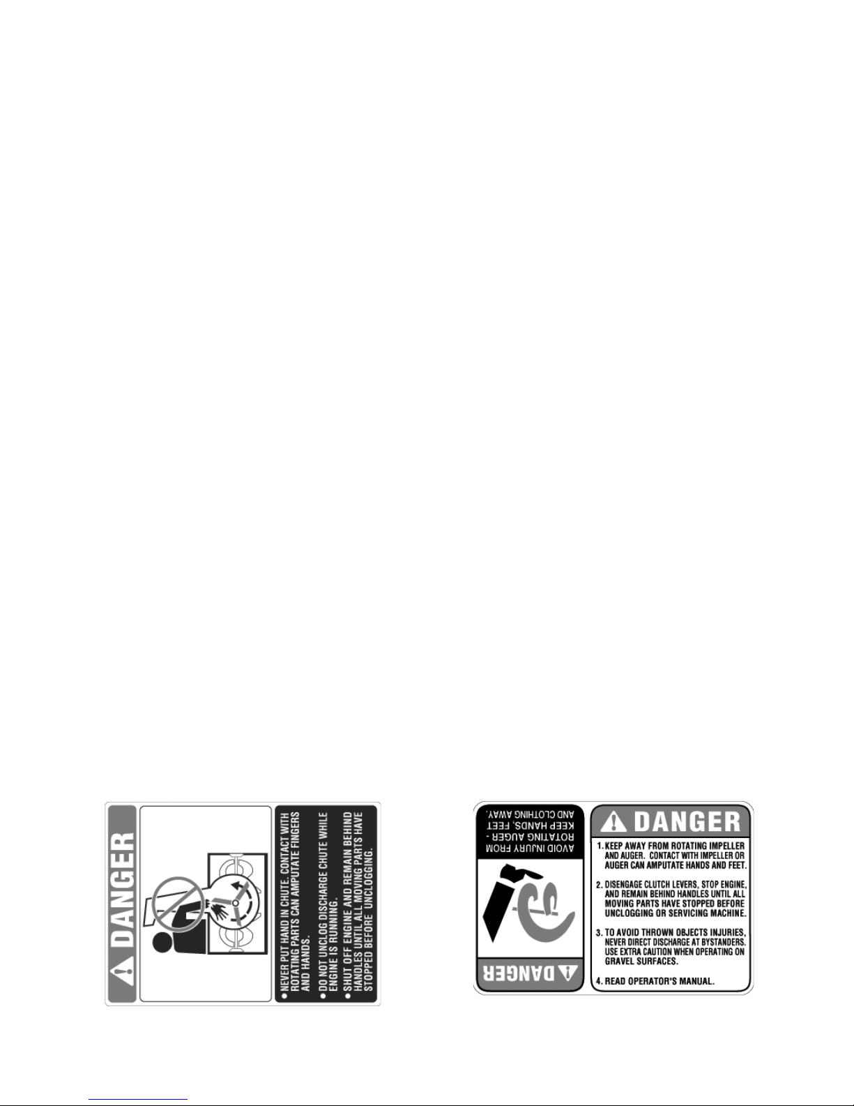
Your Responsibility
Restrict the use of this power machine to persons who
read, understand and follow the warnings and
instructions in this manual and on the machine. The
safety labels are shown below for your reference.
4
SECTION 2: ASSEMBLING YOUR SNOW THROWER
Unpacking
• Remove staples from the top, sides, and ends of
the shipping crate.
• Set panels aside to avoid tire punctures or personal
injury.
• Remove and discard plastic bag that covers unit.
• Roll the unit out of the crate.
• Check the crate for loose parts before discarding.
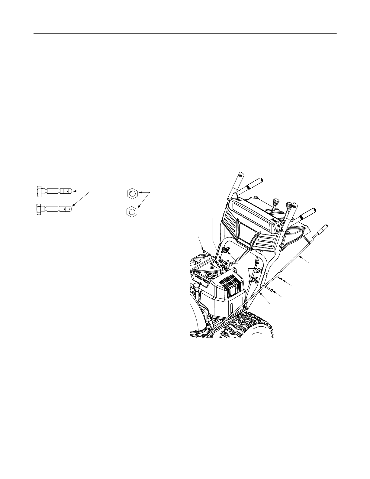
Loose Parts
• The augers are secured to the auger shaft with two
shear bolts and hex lock nuts. If you hit a foreign
object or ice jam, the snow thrower is designed so
that the bolts may shear. Two replacement shear
bolts and nuts are provided for your convenience.
See Figure 1. Store these safely until needed.
Shear Bolts
Figure 1
IMPORTANT:
with standard hex bolts. Any damage to the auger
gearbox or other components from using standard bolts
will not be covered by your snow thrower’s warranty.
NEVER replace the auger shear bolts
Hex Lock
Nuts
Items Required For Assembly
1. Pair of pliers
2. Engine oil
3. Fresh gasoline
Before Assembly
• Disconnect spark plug wire and ground it against
the engine to prevent unintended starting.
roller guides. Make sure the spring ( found at the
end of each cable) is attached to its actuator
bracket.
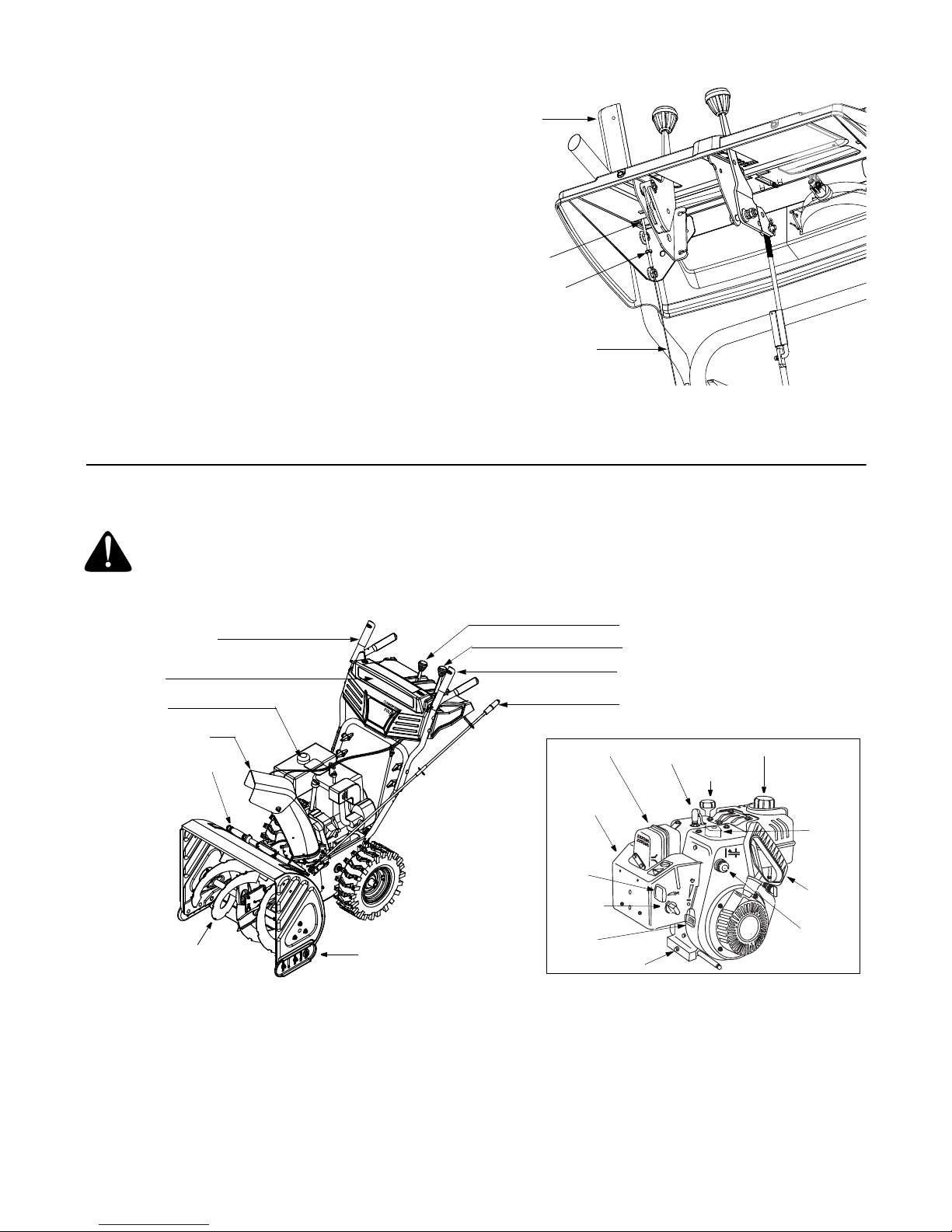
• Secure the upper handle and lower handle with the
two plastic wing nuts, saddle washers and carriage
bolts previously removed. Attach these hardware
on the lower hole in the handles. See Figure 2.
• Tighten the two wing nuts already in pl ace on the
upper holes and secure the handles firmly. Slide
the shift rod connector down over the end of the
lower shift rod. Tap the connector until it locks over
the lower shift rod. See Figure 2.
NOTE: If the connector is not properly assembled, the
shift rod will pivot and you will not be able to change
speed or direction of movement of the equipment.
Carriage
Bolt
Saddle
Washer
Wing
Nut
Hairpin Clip
Carriage Bolt
Lower Chute Crank
Upper
Chute
Crank
NOTE: All references in this manual to the left or right
side of the snow thrower is from the operating position
only. Exceptions, if any, will be specified.
Assembling Handle
For shipping purposes, the upper hand le is secured
loosely to the lower handle with four wing nuts.
• Remove the lower plastic wing nut, saddle washer
and carriage bolt from each side of the lower
handle. See Figure 2.
• Raise the upper handle assembly until it locks over
the lower handle.
• Look at the lower rear of the snow thrower frame to
be sure all the cables are aligned with the cable
Figure 2
Attaching Chute Crank
• Remove the hairpin clip from the upper ch ute crank
and slide the upper chute crank into the lower chute
crank. A pair of pliers may help in this job.
• Align the two holes on both chute cranks and insert
the hairpin clip removed earlier, through these
holes. See Figure 2.
• If not already attached, slip the chute cables
(running from the handle panel to the discharge
chute) into the cable guide located on top of the
engine. See Figure 3.
5
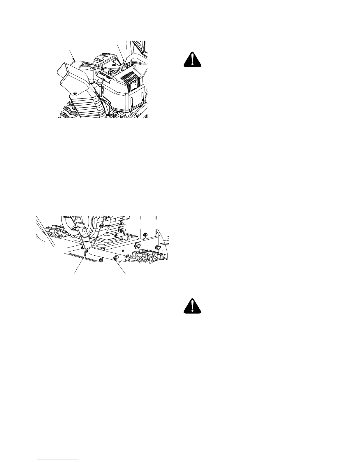
Cable Guide
Cable
Figure 3
Connecting Alternator Lead
(Model 8526 Only)
• Unwrap the headlight wire which is attached to the
headlight, beneath the handle panel. Wind the
headlight wire around the lower r ight handle until
excess slack is removed. See Figure 4.
• Plug the wire from the headlight into the alternat or
lead coming from the right side of the engine
underneath the fuel tank.
Alternator Lead
NOTE: If the tire pressure is not equal in all tires, the
unit may pull to one side or the othe r.
WARNING: Maximum tire p ressure under
any circumstance is 30 psi. Equal tire pressure
should be maintained at all times. Excessive
pressure (over 30 psi) when seating beads
may cause tire/rim assembly to burst with force
sufficient to cause serious injury.
Traction Control & Shift Lever
Move the shift lever into sixth (6) position. Perfor m the
following test to check for proper adjustment:
1. With the traction control r eleased, push the sn ow
thrower forward, then pull it back. The machine
should move freely.
2. Engage the traction control and attempt to move
the machine both forward and back. Resistance
should be felt.
3. Move the shift lever into the fast reverse (R2)
position and repeat the previous two steps.
If you experienced resistance in the first or the third
case, or no resistance in the second case, adjust
traction control. To adjust, proceed as follows:
• Loosen the jam nut on the traction control ca ble
and unthread the cable one full turn.
• Recheck adjustment.
• Retighten the jam nut to secure the cable when
correct adjustment is reached.
Lamp Wire
Figure 4
Right Handle
Chute Clean-Out Tool
• This tool, along with the electric cord, may be
fastened with a cable tie to the rear ofthe auger
housing for shipping purposes. In that case, cut the
cable tie and remove the electric cord now.
Final Adjustments
Make these final adjustments before operating your
snow thrower for the first time. Failure to follow these
instructions may cause damage to the snow thrower.
NOTE: If you have a question about the terms used in
these instructions, refer to the descriptions and
illustration starting on page 7.
Tire Pressure (Pneumatic Tires)
The tires are overinflated for shipping purpos es.
• Check tire pressure. Maintain pressure as
recommended on the sidewall of the tire.
NOTE: For more details, refer to Traction Control
Adjustment on page 10.
Auger Control
Check the adjustment of the auger control as follows:
• When the auger control is released and in the
disengaged “up” position, the cable should ha ve
very little slack, but should not be tight.
WARNING: Do not over-tighten the cable.
Over-tightening may prevent t he auger fro m
disengaging and compromise the safety of the
snow thrower.
• In a well-ventilated area, start the snow thrower
engine as instructed on page 8. Make sure the
throttle is set in the fast position.
• While standing in the operator’s position (behind
the snow thrower) engage the auger.
• Allow the auger to remain engaged for
approximately ten (10) seconds befo re releasing
the auger control. Repeat this several times.
• With the engine running in the fast position and the
auger control lever in the disengaged “up” position,
walk to the front of the machine.
• Confirm that the auger has completely stopped
rotating and shows no signs of motion.
6
IMPORTANT:
STOP
immediately return to the operator’s position and shut
off the engine. Wait for all moving parts to stop before
If the auger shows any signs of rotating,
Auger
Control
readjusting the auger control cable.
• To readjust the control cable, loosen the hex jam
nut on the auger control cable “Z” fitting.
• Rotate the coupling end of the cable
counterclockwise to provide more slack.
• Retighten the hex jam nut. See Figure 5.
• Repeat Auger Control Test to verify adjustment.
Z-End
Jam Nut
Auger
Control Cable
SECTION 3: KNOW YOUR SNOW THROWER
WARNING: Be familiar with all the controls on the snow thrower and their proper operation. Know how to
stop the machine and disengage them quickly.
Figure 5
• Compare the figure below and description of controls in this se ction with your equipment before start ing unit.
Traction Control /
Auger Control Lock
Headlight*
Fuel Tank
Discharge Chute
Chute Clean-Out Tool
Auger
* Model 8526 only
Skid Shoe
Carburetor
Cover
Ignition
Key
Choke
Throttle
Control
Shift Lever
Chute Tilt Control
Auger Control
Chute Directional Control
Muffler
Spark Plug
Oil Fill
Oil Drain
Fuel Cap
Electric
Starter
Starter
Handle
Primer
Figure 6
Traction Control / Auger Control Lock
The traction control is located on t he right handle.
Squeeze the traction control to enga ge the wheel drive;
release to stop.
This same lever also locks the auger control so you can
operate the chute crank without interrupting snow
throwing process. If the auger control is engaged
simultaneously with the traction control, you can
release the auger control (on the left handle) and the
augers will remain engaged. Release the traction
control to stop the augers and wheel drive (the auger
control must also be released).
7
IMPORTANT:
Always release the traction control before
changing speeds.
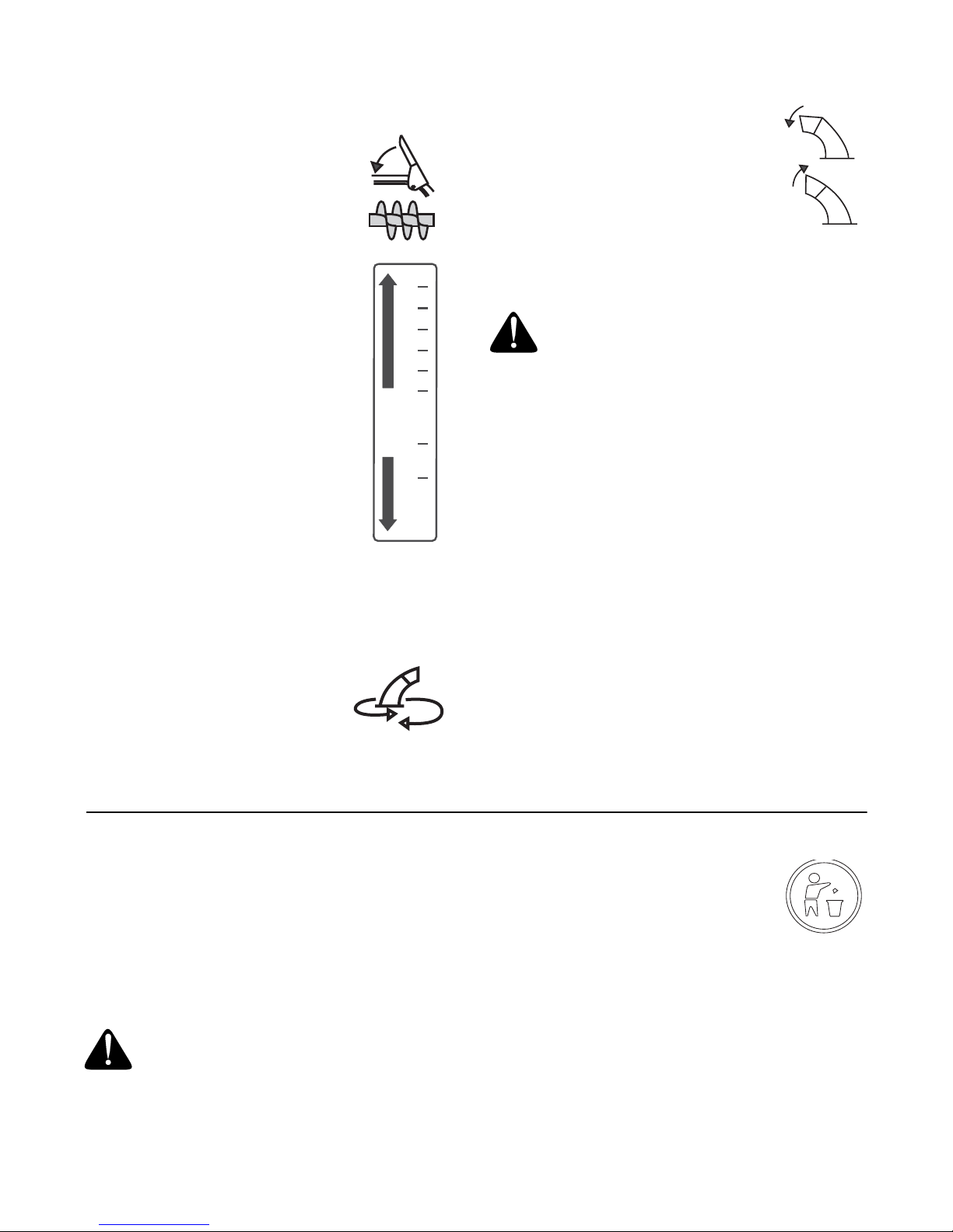
Auger Control
The auger control is located on the left
handle. Squeeze the auger control to
engage the augers; release to
disengage. Traction control must also
be released in order to stop the auger.
Shift Lever
F
R
6
5
4
3
2
1
R1
R2
The shift lever is located in the center
of the handle panel and is used to
determine ground speed and direction
of travel. It can be moved into any of
eight positions.
IMPORTANT:
Always release traction
the control before changing speeds.
Forward: The snow thrower has six
forward (F) speeds. Position one (1) is
the slowest and position six (6) is the
fastest.
Reverse: The snow thrower has two
reverse (R) speeds—R1 is the slower
of the two.
Discharge Chute
The angle of the upper discharge chute controls the
distance that snow is thrown. Tilt the discharge chute
up for greater distance; tilt it down for less distance.
Chute Crank
The chute crank is located on the left
side of the snow thrower. Use it to
change direction in which snow is
thrown. Avoid targetting persons,
animals or cars and buildings.
CLOCKWISE TO
DISCHARGE LEFT
COUNTER CLOCKWISE
TO DISCHARGE RIGH
Chute Tilt Control
The distance snow is thrown can be
changed by adjusting the angle of the
chute assembly. Move chute tilt control
forward to decrease distance, and
toward the rear to increase distance.
Chute Clean-Out Tool
The chute clean-out tool is designed to clear a clogged
discharge chute. Refer to page 10 for details.
WARNING: Never use your hand to clear a
clogged discharge chute. Shut off engine and
remain behind handles until all moving parts
have stopped before unclogging.
Skid Shoe
The skid shoe position has to be determined by the
condition of the ground from where snow will be
removed. Higher the snow level, lower will be the skid
shoe. Adjust it accordingly.
Headlight
(Model 8526 only)
The headlight is on whenever the engine is running.
Throttle Control
The throttle control is located on the engine. I t regulates
the speed of the engine.
Safety Ignition Key
The safety ignition key must be fully inserted in the
switch before the unit will start. Remove key when snow
thrower is not in use. Do not turn the key.
T
SECTION 4: OPERATING YOUR SNOW THROWER
Read and understand all instructions and warnings on
the machine and in this manual before operating the
snow thrower.
Gas & Oil Fill-Up
• Service the engine with gasoline and oil as
instructed in the engine manual shipped with the
snow thrower.
WARNING: Use extreme care when
handling gasoline. Gasoline is extremely
flammable and the vapors are explosive. Never
fuel machine indoors or while the eng ine is hot
or running. Extinguish cigarettes, cigars, pipes
an other sources of ignition.
IMPORTANT:
Your snow thrower is
equipped with a plastic fuel tank insert for
shipping purposes. Please discard it
before filling up gasoline for the first time.
To Start Engine
NOTE: If unit shows any sign of motion (drive or
augers) with the clutch grips disengaged, shut engine
off immediately. Readjust as instructed in the Final
Adjustments in the Assembly Section.
• Attach spark plug wire to spark plug. Make certain
the metal loop on end of the spark plug wire (inside
the boot) is fastened securely over the metal tip on
the spark plug.
8
 Loading...