

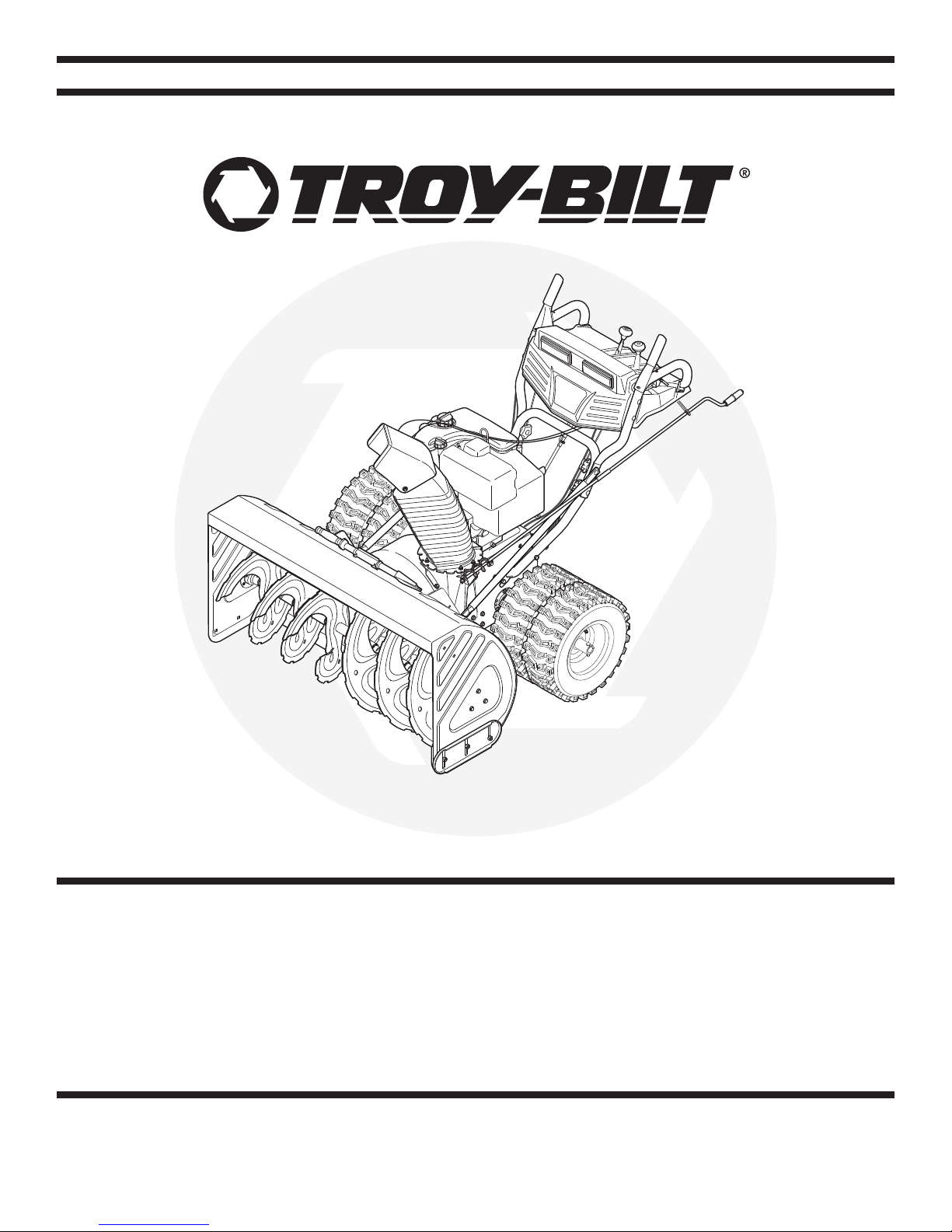
Troy-Bilt Storm 13045 Operator's Manual
Safety • Assembly • Operation • Tips & Techniques • Maintenance • Troubleshooting • Parts Lists • Warranty
OPERATOR’S MANUAL
Two-Stage Snow Thrower – Storm 13045
READ SAFETY RULES AND INSTRUCTIONS CAREFULLY BEFORE OPERATION
Warning: This unit is equipped with an internal combustion engine and should not be used on or near any uniiproved forest-covered, brush-
covered or grass-covered land unless the engine’s exhaust system is equipped with a spark arrester meeting applicable local or state laws (if any).
If a spark arrester is used, it should be maintained in effective working order by the operator. In the State of California the above is required by law
(Section 4442 of the California Public Resources Code). Other states may have similar laws. Federal laws apply on federal lands. A spark arrester
for the muffler is available through your nearest engine authorized service dealer or contact the service department, P.O. Box 361131 Cleveland,
Ohio 44136-0019.
PRINTED IN U.S.A
31AH9Q77766
IMPORTANT
FORM NO. 769-00381C
6/28/06
This Operator’s Manual is an important part of your new snow thrower. It will help you assemble,
www.troybilt.com
TROY-BILT LLC
P. O. BOX
36 1 13 1
CLEVELAND, OH 44136
866-840-6483
330-558-7220
prepare and maintain the unit for best performance. Please read and understand what it says.
Table of Contents
Customer Support .............................................. 2
Safety Labels ...................................................... 3
Safe Operation Practices ................................... 4
Setting Up Your Snow Thrower .......................... 6
Operating Your Snow Thrower ......................... 10
Making Adjustments ........................................ 14
Specifications are subject to change without notification or obligation. Images may not reflect your exact model and are for reference purposes only.
Finding and Recording Model Number
BEFORE ASSEMBLING YOUR NEW EQUIPMENT:
Please locate the model plate on the equipment
and copy the information to the sample model plate
provided to the right. You can locate the model plate
by standing at the operating position and looking
down at the rear of the snow thrower. This information
will be necessary to use the manufacturer’s web site,
when contacting the Customer Service Department,
or when obtaining assistance from an authorized
Troy-Bilt service dealer.
Maintaining Your Snow Thrower ...................... 16
Off-Season Storage .......................................... 22
Troubleshooting ................................................ 23
Illustrated Parts List ......................................... 24
Warranty ............................................................ 31
Customer Support
Please do not return the unit to the retailer from which it was purchased, without first contacting Customer Support.
If you have difficulty assembling this product or have any questions regarding the controls, operation, or maintenance of this
unit, you can seek help from the experts. Choose from the options below:
• Visit
• Call a Customer Support Representative at
www.troybilt.com for many useful suggestions. Click
the Tool Bench tab to access the Troy-Bilt Solution Center.
1-866-840-6483.
• The engine manufacturer is responsible for all enginerelated issues with regard to performance, power-rating,
specifications, warranty, and service. Please refer to the
engine manufacturer’s Owner’s/Operator’s Manual, packed
separately with your unit, for more information.
2
+%%0!7!9&2/-2/4!4).')-0%,,%2
!.$!5'%2#/.4!#47)4()-0%,,%2/2
!5'%2#!.!-054!4%(!.$3!.$&%%4
53%#,%!./544//,4/5.#,/'
$)3#(!2'%#(54%
$)3%.'!'%#,54#(,%6%2334/0%.').%
!.$2%-!)."%().$(!.$,%35.4),!,,
-/6).'0!243(!6%34/00%$"%&/2%
5.#,/'').'/23%26)#).'-!#().%
4/!6/)$4(2/7./"*%#43).*52)%3
.%6%2$)2%#4$)3#(!2'%!4"934!.$%23
53%%842!#!54)/.7(%./0%2!4).'/.
'2!6%,352&!#%3
2%!$/0%2!4/2g3-!.5!,
$!.'%2
#,%!. /54 4//,
$!.'%2
!6/)$).*529&2/2/4!4).'!5'%2
+%%0(!.$3&%%4
!.$#,/4().'!7!9
$!.'%2
.%6%2054(!.$).#(54%#/.4!#47)4(
2/4!4).'0!243#!.!-054!4%&).'%23
!.$(!.$3
3( 54/&&%.') .%!.$ 7!) 45.4) ,!,,
-/6).' 0!243(!6 %34/ 00%$"%&/2%
5.#,/'').'
53%#,%!./544//,/27//$%.
34)#+4/
5.#,/'$)3#(!2'%#(54%
1
Safety
Labels
WARNING
This symbol points
out important safety
instructions which, if
not followed, could
endanger the personal
safety and/or property
of yourself and others.
Read and follow all
instructions in this
manual before attempting to operate
this machine. Failure
to comply with these
instructions may result
in personal injury. When
you see this symbol.
HEED ITS WARNING!
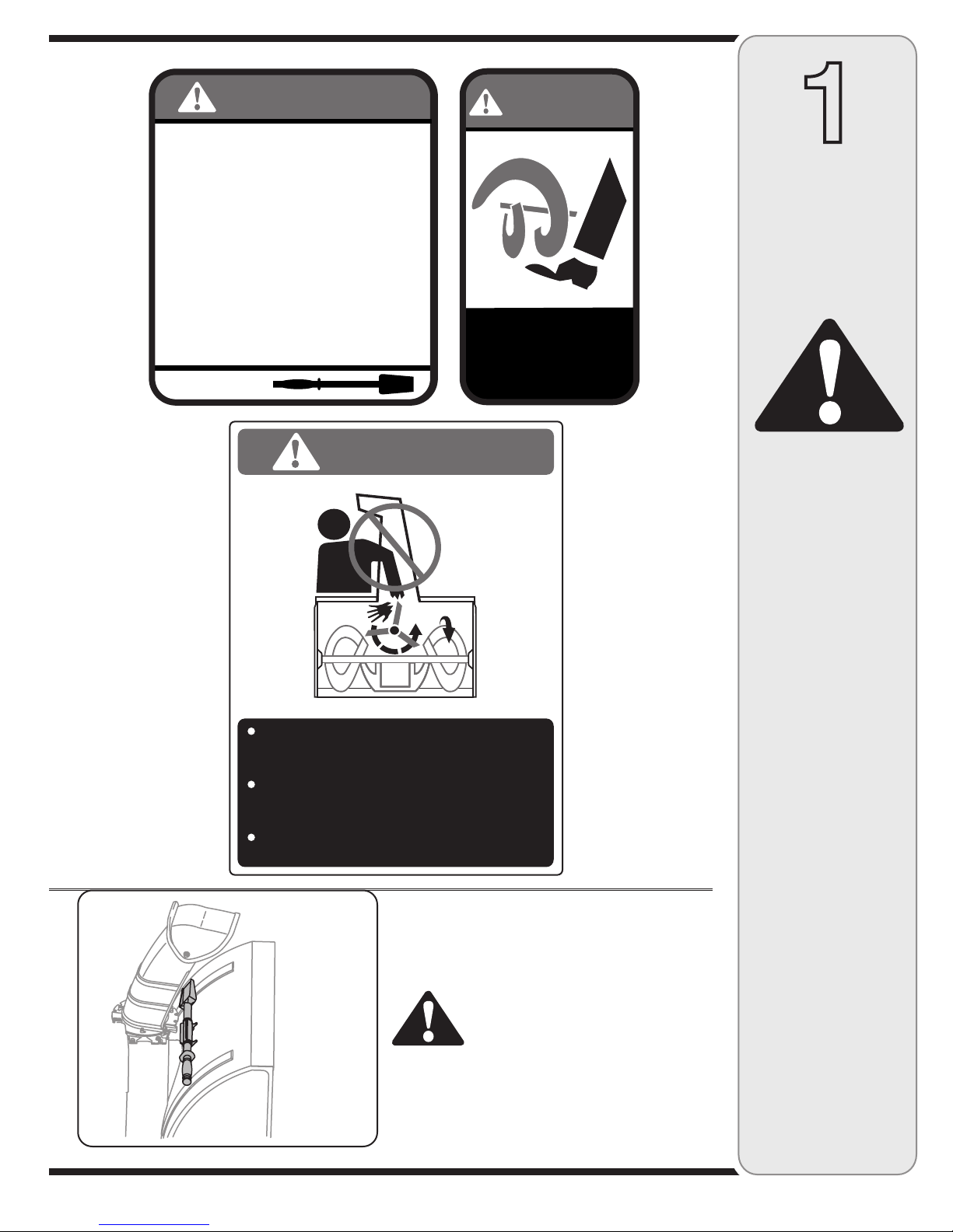
A chute clean-out tool is fastened to the top of the
auger housing with a mounting clip. The tool is designed
to clear a chute assembly of ice and snow.
This item is fastened with a cable tie at the factory. Cut
the cable tie before operating the snow thrower.
3
Your Responsibility
Restrict the use
of this power machine
to persons who read,
WARNING: Never use your
hands to clear a clogged chute
assembly. Shut off engine and
remain behind handles until
all moving parts have stopped
before using the clean-out tool
to clear the chute assembly.
understand
and follow the warnings
and instructions
in this manual
and on the machine.
WARNING: Engine Exhaust, some of its constituents, and certain vehicle components contain or emit chemicals known to State of California to cause cancer and
birth defects or other reproductive harm.
2
Safe
Operation
Practices
WARNING
This symbol points
out important safety
instructions which, if
not followed, could
endanger the personal
safety and/or property
of yourself and others.
Read and follow all
instructions in this
manual before attempting to operate
this machine. Failure
to comply with these
instructions may result
in personal injury. When
you see this symbol.
HEED ITS WARNING!
Your Responsibility
Restrict the use
of this power machine
to persons who read,
understand
and follow the warnings
and instructions
in this manual
and on the machine.
DANGER: This machine was built to be operated according to the rules for safe operation in this
manual. As with any type of power equipment, carelessness or error on the part of the operator can
result in serious injury. This machine is capable of amputating hands and feet and throwing objects.
Failure to observe the following safety instructions could result in serious injury or death.
Training
1. Read, understand, and follow all instructions on the
machine and in the manual(s) before attempting to
assemble and operate. Keep this manual in a safe place for
future and regular reference and for ordering replacement
parts.
2. Be familiar with all controls and their proper operation.
Know how to stop the machine and disengage them quickly.
3. Never allow children under 14 years old to operate this
machine. Children 14 years old and over should read and
understand the operation instructions and safety rules in
this manual and should be trained and supervised by a
parent.
4. Never allow adults to operate this machine without proper
instruction.
5. Thrown objects can cause serious personal injury. Plan
your snow-throwing pattern to avoid discharge of material
toward roads, bystanders and the like.
6. Keep bystanders, helpers, pets and children at least 75 feet
from the machine while it is in operation. Stop machine if
anyone enters the area.
7. Exercise caution to avoid slipping or falling, especially
when operating in reverse.
1. Thoroughly inspect the area where the equipment is to be
used. Remove all doormats, newspapers, sleds, boards,
wires and other foreign objects, which could be tripped over
or thrown by the auger/impeller.
2. Always wear safety glasses or eye shields during operation
and while performing an adjustment or repair to protect your
eyes. Thrown objects which ricochet can cause serious
injury to the eyes.
3. Do not operate without wearing adequate winter outer
garments. Do not wear jewelry, long scarves or other
loose clothing, which could become entangled in moving
parts. Wear footwear which will improve footing on slippery
surfaces.
4. Use a grounded three-wire extension cord and receptacle
for all units with electric start engines.
5. Adjust collector housing height to clear gravel or crushed
rock surfaces.
6. Disengage all control levers before starting the engine.
7. Never attempt to make any adjustments while engine is
running, except where specifically recommended in the
operator’s manual.
8. Let engine and machine adjust to outdoor temperature
before starting to clear snow.
9. To avoid personal injury or property damage use extreme
care in handling gasoline. Gasoline is extremely flammable
and the vapors are explosive. Serious personal injury can
occur when gasoline is spilled on yourself or your clothes,
which can ignite. Wash your skin and change clothes
immediately.
a. Use only an approved gasoline container.
b. Extinguish all cigarettes, cigars, pipes and other sources
of ignition.
c. Never fuel machine indoors.
d. Never remove gas cap or add fuel while the engine is hot
or running.
e. Allow engine to cool at least two minutes before refuel
ing.
f. Never over fill fuel tank. Fill tank to no more than ½ inch
below bottom of filler neck to provide space for fuel
expansion.
g. Replace gasoline cap and tighten securely.
h. If gasoline is spilled, wipe it of f the engine and equip
ment. Move machine to another area. Wait 5 minutes
before starting the engine.
i. Never store the machine or fuel container inside where
there is an open flame, spark or pilot light (e.g. furnace,
water heater, space heater, clothes dr yer etc.).
j. Allow machine to cool at least 5 minutes before storing.
Preparation
-
-
4
Operation
1. Do not put hands or feet near rotating parts, in the
auger/impeller housing or chute assembly. Contact with the
rotating parts can amputate hands and feet.
2. The auger/ impeller control lever is a safety device. Never
bypass its operation. Doing so makes the machine unsafe
and may cause personal injury.
3. The control levers must operate easily in both directions
and automatically return to the disengaged position when
released.
4. Never operate with a missing or damaged chute assembly.
Keep all safety devices in place and working.
5. Never run an engine indoors or in a poorly ventilated area.
Engine exhaust contains carbon monoxide, an odorless and
deadly gas.
6. Do not operate machine while under the influence of alcohol
or drugs.
7. Muffler and engine become hot and can cause a burn. Do
not touch.
8. Exercise extreme caution when operating on or crossing
gravel surfaces. Stay alert for hidden hazards or traffic.
9. Exercise caution when changing direction and while operat
ing on slopes.
10. Plan your snow-throwing pattern to avoid discharge towards
windows, walls, cars etc. Thus, avoiding possible property
damage or personal injury caused by a ricochet.
11. Never direct discharge at children, bystanders and pets or
allow anyone in front of the machine.
12. Do not overload machine capacity by attempting to clear
snow at too fast of a rate.
13. Never operate this machine without good visibility or light.
Always be sure of your footing and keep a firm hold on the
handles. Walk, never run.
14. Disengage power to the auger/impeller when transporting or
not in use.
15. Never operate machine at high transpor t speeds on slippery
surfaces. Look down and behind and use care when
backing up.
16. If the machine should start to vibrate abnormally, stop the
engine, disconnect the spark plug wire and ground it against
the engine. Inspect thoroughly for damage. Repair any
damage before starting and operating.
17. Disengage all control levers and stop engine before you
leave the operating position ( behind the handles). Wait
until the auger/impeller comes to a complete stop before
unclogging the chute assembly, making any adjustments, or
inspections.
18. Never put your hand in the discharge or collector openings.
Always use the clean-out tool provided to unclog the dis-
charge opening. Do not unclog chute assembly while engine
is running. Shut off engine and remain behind handles until
all moving parts have stopped before unclogging.
19. Use only attachments and accessories approved by the
manufacturer (e.g. wheel weights, tire chains, cabs etc.).
20. If situations occur which are not covered in this manual,
use care and good judgment. Contact your dealer for
assistance.
Maintenance & Storage
1. Never tamper with safety devices. Check their proper
operation regularly. Refer to the maintenance and adjust-
ment sections of this manual.
2. Before cleaning, repairing, or inspecting machine disen
gage all control levers and stop the engine. Wait until the
auger/impeller come to a complete stop. Disconnect the
spark plug wire and ground against the engine to prevent
unintended starting.
3. Check bolts and screws for proper tightness at frequent
intervals to keep the machine in safe working condition.
Also, visually inspect machine for any damage.
4. Do not change the engine governor setting or over-speed
the engine. The governor controls the maximum safe
operating speed of the engine.
5. Snow thrower shave plates and skid shoes are subject to
wear and damage. For your safety protection, frequently
check all components and replace with original equipment
manufacturer’s (OEM) par ts only. “Use of parts which do
not meet the original equipment specifications may lead to
improper per formance and compromise safety !”
6. Check controls periodically to verify they engage and
disengage properly and adjust, if necessary. Refer to the
adjustment section in this operator’s manual for instructions.
7. Maintain or replace safety and instruction labels, as neces
sary.
8. Observe proper disposal laws and regulations for gas, oil,
etc. to protect the environment.
9. Prior to storing, run machine a few minutes to clear snow
from machine and prevent freeze up of auger/impeller.
10. Never store the machine or fuel container inside where
there is an open flame, spark or pilot light such as a water
heater, furnace, clothes dryer etc.
11. Always refer to the operator’s manual for proper instructions
on off-season storage.
Do not modify engine
To avoid serious injury or death, do not modify engine in any
way. Tampering with the governor setting can lead to a runaway
engine and cause it to operate at unsafe speeds. Never tamper
with factory setting of engine governor.
Notice regarding Emissions
Engines which are certified to comply with California and federal
EPA emission regulations for SORE (Small Off Road Equipment)
are certified to operate on regular unleaded gasoline, and may
include the following emission control systems: Engine Modification (EM) and Three Way Catalyst (TWC) if so equipped.
Your Responsibility
Restrict the use of this power machine to persons who read, understand and follow the warnings and instructions in this manual
and on the machine.
-
2
Safe
Operation
Practices
WARNING
-
This symbol points
out important safety
instructions, which if
not followed, could
endanger the personal
safety and/or property
of yourself and others.
Read and follow all
instructions in this manual before attempting to
operate this machine.
Failure to comply with
these instructions may
result in personal injury.
When you see this
symbol.
HEED IT’S WARNING!
Your Responsibility
Restrict the use
of this power machine
to persons who read,
understand
and follow the warnings
and instructions
in this manual
and on the machine.
5
3
Setting Up
Your Snow
Thrower
NOTE: All references
in this manual to the
left or right side of the
snow thrower is from
the operating position
only. Exceptions, if any,
will be specified.
IMPORTANT
This unit is shipped
with the engine full of
oil. After assembly,
refer to the Tecumseh
Engines manual
packed separately with
your snow thrower
for fuel and oil fill-up
details.
Figure 3-1
Figure 3-2
IMPORTANT: Two replacement auger shear pins are
included with this manual. Refer to the Maintenance
section for more information regarding shear pin replacement.
NOTE: All references in this manual to the left or right
side of the snow thrower is from the operating position
only. Exceptions, if any, will be specified.
IMPORTANT: This unit is shipped with the engine full of
oil. After assembly, refer to the Tecumseh Engine manual
packed separately with your snow thrower for fuel and oil
fill-up details.
1. Observe the lower area of the snow thrower to be sure
that all cables (steering, auger, and drive) are properly
routed and not pinched or kinked before pivoting
handle upward.
a. Remove the lower star knob and carriage bolt from
each side of the lower handle. Pull up and back on
upper handle as shown in Figure 3-1. Align upper
handle with the lower handle. Make certain the
springs at the lower end of the auger and drive
cables are securely hooked into their respective
actuator bracket.
2. a. Secure the upper handle and lower handle with the
two star knobs and carriage bolts removed earlier.
See Figure 3-2.
b. Tighten the two star knobs already installed in the
upper holes to firmly secure the upper handle and
support tubes.
3. Align the upper and lower shift rods, then slide the
shift rod connector down over the end of the lower
shift rod. Tap the connector until the lower rod is
completely through the connector. See Figure 3-3.
NOTE: If the connector is not properly assembled, the
shift rod will pivot and you will not be able to change
speeds or direction.
Specifications are
subject to change
without notification
or obligation. Images
may not reflect your
exact model and are for
reference purposes only.
a
b
Figure 3-3 Figure 3-4
6
NOTE: If the full range of speeds (forward and reverse)
can not be achieved, refer to the “Making Adjustments”
section.
4. a. Remove the internal cotter pin from the upper chute
crank. Slide the upper chute crank into the sleeve
on the lower chute crank.
b. Align the hole in the upper chute crank with the
hole in the sleeve (If necessary, use a pair of pliers
to assist in aligning holes). Insert the internal cotter
pin through the holes to secure the chute crank.
See Figure 3-4.
5. Remove lock nuts and screws securing one of the
flange keepers to the chute assembly.
6. Place chute assembly onto chute base as shown in
Figure 3-5, making sure that the notches engage with
the spiral end of chute directional control.
7. Secure flange keeper removed earlier with lock nuts
and screws. Tighten down nuts securing the other two
flange keepers. See Figure 3-6.
8. If not already done, slip the cables that run from the
handle panel to the discharge chute into the cable
guide located on top of the engine. See Figure 3-7.
9. If not already done, wrap the wire of the head lamp
wire harness down the right handle until the wire can
be plugged into the engine alternator wire connector
down on the engine. See Figure 3-8.
10. Normally the cable ties holding the steering cables
against the handle are loosely installed on each side
of the lower handle at the factory. Pull the cable ties
tight to secure. Cut the excess from the ends of cable
ties.
The extension cord is fastened with a cable tie to the rear
of the auger housing for shipping purposes. Cut the cable
tie and remove it before operating the snow thrower.
Figure 3-5
Figure 3-6
3
Setting Up
Your Snow
Thrower
IMPORTANT
Prior to operating
your snow thrower,
refer to Auger Control
Test in the Operation
section. Read and
follow all instructions
carefully and perform
all adjustments to verify
your snow thrower is
operating safely and
properly.
Figure 3-8
Figure 3-7
7

Chute Tilt Control
Shift Lever
3
Setting Up
Your Snow
Thrower
Specifications are
subject to change
without notification
or obligation. Images
may not reflect your
exact model and are
for reference purposes
only.
Auger
Control
Auger
Control
Cable
Drive
Control
Drive
Control
Cable
Figure 3-9
Final Adjustments
Make these final assembly adjustments before
operating your snow thrower for the first time. Failure
to follow these instructions may cause damage to the
snow thrower.
Testing Drive Control & Shift Lever
Refer to Figure 3-9 for location of controls.
1. Move the shift lever into sixth (6) position.
2. With the wheel drive control released, push the
snow thrower forward, then pull it back. The machine
should move freely.
3. Engage the drive control and attempt to move the
machine both forward and back, resistance should
be felt.
4. Move the shift lever into the fast reverse (R2)
position and repeat the previous two steps.
If you experienced resistance rolling the unit, either
when repositioning the shift lever from 6 to R2 or when
attempting to move the machine with the drive control
released, adjust the drive control immediately. See
Adjusting Drive and Auger Controls.
Testing Auger Drive Control
When the auger control is released and in the disengaged
“up” position, the cable should have very little slack, but
should NOT be tight.
1. In a well-ventilated area, start the snow thrower
engine as instructed in the Operation section. Make
sure the throttle is set in the fast position.
2. While standing in the operator’s position (behind the
snow thrower), engage the auger control and allow
the auger to remain engaged for approximately ten
seconds before releasing the auger control. Repeat
this several times.
3. With the engine running in the fast position and the
auger control in the disengaged “up” position, walk to
the front of the machine.
Confirm that the auger has completely stopped
rotating and shows no signs of motion.
4. If the auger shows any signs of rotating, immediately
return to the operator’s position and shut off the
engine. Wait for all moving parts to stop before
readjusting the auger control cable.
8
Adjusting Drive and Auger Controls
1. From beneath the handle, pull downward on the
appropriate cable and unhook the spring found on the
end of the cable from its respective actuator bracket.
Refer to Figures 3-9 and 3-10.
2. Slide the spring up the cable to expose the cable
coupler threads and lock nut. Refer to Figure 3-11.
Adjust the lock nut as follows:
3. If adjusting the drive cable, thread the lock nut
outward (down the coupler) to lengthen the cable
and allow the unit to move freely when the control is
released. Thread the lock nut inward (up the coupler)
to shorten the cable to reduce slippage and prevent
the machine from being easily moved with the drive
control engaged.
4. If adjusting the auger cable, thread the lock nut down
to lengthen the cable as necessary to stop the auger
from turning when the control is released.
3
Setting Up
Your Snow
Thrower
Figure 3-10
WARNING: Do not over-tighten the
cable. Over-tightening may prevent the
auger from disengaging and compromise the safety of the snow thrower.
5. Reattach the spring to the actuator bracket.
6. Repeat the wheel drive and auger control tests to
verify proper adjustment. Repeat previous steps if
necessary to attain proper adjustment of each cable.
Tire Pressure (Pneumatic Tires)
The tires are over-inflated for shipping purposes. Check
the tire pressure before operating the snow thrower. Refer
to the tire side wall for tire manufacturer’s recommended
psi and deflate (or inflate) the tires as necessary.
NOTE: If the tire pressure is not equal in both tires, the
unit may pull to one side or the other and the shave plate
will not sit level on the ground.
IMPORTANT: Under any circumstance do not exceed
manufacturer’s recommended psi. Equal tire pressure
should be maintained at all times. Excessive pressure
when seating beads may cause tire /rim assembly to
burst with force sufficient to cause serious injury. Refer to
sidewall of tire for recommended pressure.
Figure 3-11
WARNING
Do not over-tighten the
cable. Over-tightening may
prevent the auger from
disengaging and compromise the safety of the snow
thrower.
IMPORTANT: Under any
circumstance do not
exceed manufacturer’s
recommended psi. Equal
tire pressure should be
maintained at all times.
Excessive pressure when
seating beads may cause
tire/rim assembly to burst
with force sufficient to
cause serious injury.
Refer to sidewall of tire for
recommended pressure.
Specifications are subject
to change without notification or obligation. Images
may not reflect your exact
model and are for reference purposes only.
9
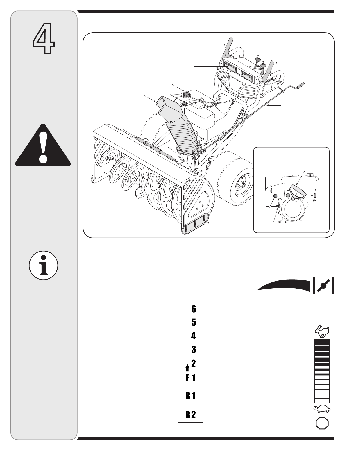
Know Your Snow Thrower
34/0
4
Operating
Your Snow
Thrower
WARNING
Read, understand,
and follow all instructions and warnings
on the machine and
in this manual before
operating.
Drive Control
Headlights
Gas Cap
Chute Assembly
Clean-Out Tool
Now that you have setup your snow thrower, it’s important to become acquainted with its controls and features.
Oil Fill
Skid Shoe
Figure 4-1
Shift Lever
Chute Tilt Control
Ignition
Key
Choke
Control
Throttle
Control
Auger Control
Wheel Steering
Control
Chute
Directional
Control
Engine Controls
Recoil Starter
Primer
Handle
Electric
Starter
Outlet
For detailed starting
instructions and
more information on
all engine controls,
refer to the Tecumseh
Engine manual
packed separately.
Specifications are
subject to change
without notification
or obligation. Images
may not reflect your
exact model and
are for reference
purposes only.
NOTE: For detailed starting instructions and more
information on all engine controls, refer to the
Tecumseh Engines manual packed separately and
Starting The Engine later in this section.
Shift Lever
The shift lever is located in the center of
the handle panel. Place the shift lever
into any of eight positions to control the
direction of travel and ground speed.
Forward
Your snow thrower has six forward (F)
speeds, with position number one (1)
being the slowest speed.
Reverse
Your snow thrower has two reverse (R)
speeds, with position number one (1)
being the slower speed.
Choke Control
The choke control
is found on the rear
of the engine and is
activated by rotating the knob clockwise. Activating the
choke control closes the choke plate on the carburetor
and aids in starting the engine.
Throttle Control
The throttle control is located on the engine.
It regulates the speed of the engine and
will shut off the engine when pushed down
completely.
Primer
Depressing the primer forces fuel directly into
the engine’s carburetor to aid in cold-weather
starting.
Oil Fill
Engine oil level can be checked and oil added
through the oil fill.
10
 Loading...