

Troy-Bilt SpringAssist TB25ET Operator's Manual

Gasoline
v®
Trimmer / Edger
el TB25ET
iMPORTANT: READ SAFETY RULES AND iNSTRUCTiONS CAREFULLY
PiN 769-01344 (10/04)
PRINTED IN USA

THANK YOU
Thank you for buying this quaHity product. This modern
outdoor power tooH wiHHprovide many hours of usefuH
service. You wiHHfind it to be a great Habor-saving device.
This operator's manuaH provides you with easy-to-
understand operating instructions. Read the whoHe
manuaH and foHHowaHHthe instructions to keep your new
outdoor power tooHin top operating condition.
PRODUCT REFERENCES, mLLUSTRATmONS
AND SPECmFmCATmONS
AHHinformation, iHHustrations, and specifications in this
manuaH are based on the Hatest product information
avaiHabHeat the time of printing. We reserve the right to
make changes at any time without notice.
Copyright#_ 2004 MTD SOUTHWEST INC, All Rights
Reserved.
TABLE OF CONTENTS
Service Information ......................... 2
Rules for Safe Operation ..................... 3
Know Your Unit ............................ 6
Assembly Instructions ....................... 7
Oil and Fuel Information ...................... 8
Starting/Stopping Instructions ................. 9
Operating Instructions ...................... 10
Maintenance and Repair Instructions ........... 13
Cleaning and Storage ....................... 20
Troubleshooting Chart ...................... 21
SERVICE iNFORMATiON
Service on this unit both within and after the warranty
period should be performed only by an authorized and
approved service dealer.
For service call 1-800-520-5520 to obtain a list of
authorized service dealers near you. For more details
about your unit, visit our website at www.troybilt.com.
DO NOT RETURN THE UNIT TO THE RETAILER.
PROOF OF PURCHASE WILL BE REQUIRED FOR
WARRANTY SERVICE.
Before beginning, locate the unit's model plate. It lists
the model and serial numbers of your unit. Refer to the
sample plate below and copy the information for future
reference.
Serial Nnmber
"-_ \ ParentPartNumbec
Medel Number
_Or)EL : /
S/N : ITEM : ,_
Specifications ............................. 22
Warranty Information ....................... 24
Parts List .................... Inside Back Cover
SPARK ARRESTOR NOTE
NOTE: For users on U.S. Forest Land and in the
states of California, Maine, Oregon and Washington.
All U.S. Forest Land and the state of California (Public
Resources Codes 4442 and 4443), Oregon and
Washington require, by Haw that certain internal
combustion engines operated on forest brush and/or
grass-covered areas be equipped with a spark arrestor,
maintained in effective working order, or the engine be
constructed, equipped and maintained for the prevention
of fire. Check with your state or local authorities for
regulations pertaining to these requirements. Failure to
follow these requirements could subject you to liability or
a fine. This unit is factory equipped with a spark
arrestor, if it requires replacement, ask your LOCAL
SERVICE DEALER to install the Accessory Part
#753-04689 Spark Arrestor Kit.
Copy the model and parent
part number here:
Copy the serial number
here:
Make sure you carefully read and understand this manual
before starting or operating this equipment.
THIS PRODUCT IS COVERED BY ONE OR MORE U.S.
PATENTS. OTHER PATENTS PENDING.
CALiFORNiA PROPOSiTiON 65 WARNING
THE ENGmNE EXHAUST FROM THINS
PRODUCT CONTAmNS CHEMICALS
KNOWN TO THE STATE OF CAUFORNmA
TO CAUSE CANCER, BmRTH DEFECTS
OR OTHER REPRODUCTmVE HARM.

The purpose of safety symboB is to attract your
attention to possiMe dangers. The safety symboB,
and their expBnations, deserve your carefui attention
and understanding. The safety warnings do not by
themseives eiiminate any danger. The instructions or
warnings they give are not substitutes for proper
accident prevention measures.
SYMBOL MEANING 1
SYMBOL MEANING
SAFETY ALERT: Undbates
warning or caution. Attention is required in
order to avoid serious personaU injury. May
be used in conjunction with other symboB
or pbtographs.
NOTE: Advises you of information or instructions vitai to
the operation or maintenance of the equipment.
Read the Operator's Manual(s} and follow all
warnings and safety instructions.
Failure to do so can result in serious injury to the
operator and/or bystanders.
danger,
FOR QUESTIONS, CALL 1o800o520o5520
,, IMPORTANT SAFETY INSTRUCTIONS ,,
READ ALL INSTRUCTIONS
BEFORE OPERATING
WARNING: When using the unit,
safety rules. Please read these instructions
Please keep these instructions for later use.
• Read the instructions carefully. Be familiar with the
controls and proper use of the unit.
Do not operate this unit when tired, iii, or under the
influence of alcohol, drugs, or medication.
Children and teens under the age of 15 must not use
the unit, except for teens guided by an adult.
• Aii guards and safety attachments must be installed
properly before operating the unit.
Inspect the unit before use. Replace damaged parts.
Check for fuel leaks. Make sure all fasteners are in
place and secure. Replace parts that are cracked,
chipped, or damaged in any way. Do not operate the
unit with loose or damaged parts.
• Carefully inspect the area before starting the unit.
Remove all debris and hard or sharp objects such as
glass, wire, etc.
Be aware of the risk of injury to the head, hands and
feet.
you must follow the
personaU injury,
WARNING: Fa,uretO obey a
result in injury to yourself and others.
Always follow the safety precautions to
reduce the risk of fire, electric shock and
personal injury.
result in property damage or personal injury
to yourself or to others. Always follow the
safety precautions to reduce the risk of fire,
electric shock and personal injury.
• Clear the area of children, bystanders, and pets. At a
minimum, keep all children, bystanders, and pets
outside a 50 feet (15 m.) radius: there still may be a
risk to bystanders from thrown objects. Bystanders
should be encouraged to wear eye protection. If you
are approached, stop the unit immediately.
• Use only 0.095 inch (2.41 mm) diameter original
equipment manufacturer replacement line. Never use
metal-reinforced line, wire or rope. These can break
off and become dangerous projectiles.
Squeeze the throttle control and check that it returns
automatically to the idle position. Make all adjustments
or repairs before using unit.
safety warning can
, Failure to obey a
• safety warning may
SAFETY WARNINGS FOR GAS UNITS
WARNING: Gaso%e is higHy
vapors can explode if ignited. Take the
following precautions:
• Store fuel only in containers specifically designed and
approved for the storage of such materials.
• Avoid creating a source of ignition for spilled fuel. Do
not start the engine until fuel vapors dissipate.
Always stop the engine and allow it to cool before filling
the fuel tank. Never remove the cap of the fuel tank, or
add fuei, when the engine is hot. Never operate the unit
without the fuel cap securely in place. Loosen the fuel
tank cap siowiy to relieve any pressure in the tank.
flammable, and its
• Mixandaddfuelinadean,welhventihtedoutdoorarea
wheretherearenosparksorflames.Slowlyremovethe
fuelcaponlyafterstoppingengine.Donotsmokewhile
fuelingormixingfuel.Wipeupanyspilledfuelfromthe
unitimmediately.Alwayswipeunitdrybeforeusing.
• Movetheunitatleast30feet(9.1m)fromthefueling
sourceandsitebeforestartingtheengine.Donot
smokeorallowsparksandopenflamesnearthearea
whileaddingfueloroperatingtheunit.
WHmLE OPERATmNG
Never start or run the unit inside a dosed room or
building. Breathing exhaust fumes can kill. Operate
this unit only in a well ventilated outdoor area.
Wear safety glasses or goggles that are marked as
meeting ANSI Z87.1-1989 standards. Also wear
ear/hearing protection when operating this unit. Wear
a face or dust mask if the operation is dusty. Long
sleeve shirts are recommended.
• Wear heavy, long pants, boots and gloves. Do not
wear loose clothing, jewelry, short pants, sandals or
go barefoot. Secure hair above shoulder level.
• The cutting attachment shield must always be in place
while operating the unit. Do not operate unit without
both trimming lines extended, and the proper line
installed. Do not extend the trimming line beyond the
length of the shield.
• This unit has a clutch. The cutting attachment remains
stationary when the engine is idling. If it does not, have
the unit adjusted by an authorized service technician.
• Adjust the handle to your size to provide the best grip.
• Be sure the cutting attachment is not in contact with
anything before starting the unit.
• Use the unit only in daylight or good artificial light.
• Avoid accidental starting. Be in the starting position
whenever pulling the starter rope. The operator and
unit must be in a stable position while starting. See
Starting/Stopping Instructions.
• Use the right tool. Only use this tool for the purpose
intended.
Do not overreach. Always keep proper footing and
balance.
Always hold the unit with both hands when operating.
Keep a firm grip on both the front and rear grips.
• Keep hands, face, and feet at a distance from all
moving parts. Do not touch or try to stop the cutting
attachment when it is rotating.
• Do not touch the engine or muffler. These parts get
extremely hot from operation. They remain hot for a
short time after you turn off the unit.
• Do not operate the engine faster than the speed
needed to cut, trim or edge. Do not run the engine at
high speed when you are not cutting.
Always stop the engine when cutting is delayed or
when walking from one cutting location to another.
• Stop and switch the engine to off for maintenance,
repair, or for changing the cutting attachment or other
attachments.
• If you strike or become entangled with a foreign
object, stop the engine immediately and check for
damage. Do not operate before repairing damage. Do
not operate the unit with loose or damaged parts.
Use only original equipment manufacturer
replacement parts and accessories for this unit. These
are available from your authorized service dealer. Use
of any unauthorized parts or accessories could lead to
serious injury to the user, or damage to the unit, and
void your warranty.
Keep unit clean of vegetation and other materials.
They may become lodged between the cutting
attachment and shield.
To reduce fire hazard, replace faulty muffler and spark
arrestor, keep the engine and muffler free from grass,
leaves, excessive grease or carbon build up.
WHILE OPERATING WiTH EDGER
• Inspect the unit before use. Ensure the bhde is
installed correctly and secure.
• Clear the area to be edged before each use. Remove
all objects such as rocks, broken glass, nails, wire, or
string which can be thrown or become entangled in
the edging attachment.
• Do not attempt to touch or stop the blade when it is
rotating.
• A coasting blade can cause injury while it continues to
spin after the engine is stopped or the throttle control
is released. Maintain proper control until the blade has
completely stopped rotating.
• Do not run the unit at high speed when not edging.
• If you strike or become entangled with a foreign
object, stop the engine immediately and check for
damage. Have any damage repaired before attempting
further operations. Do not operate unit with a bent,
cracked or dull blade. Discard blades that are bent,
warped, cracked or broken.
• Stop the engine IMMEDIATELY if you feel excessive
vibration. Vibration is a sign of trouble. Inspect thoroughly
for loose nuts, bolts or damage before continuing. Repair
or replace affected parts as necessary.
OTHER SAFETY WARNINGS
Never store the unit, with fuel in the tank, inside a
building where fumes may reach an open flame or spark.
• Allow the engine to cool before storing or transporting.
Be sure to secure the unit while transporting.
• Store the unit in a dry area, locked up or up high to
prevent unauthorized use or damage, out of the reach
of children.
Never douse or squirt the unit with water or any other
liquid. Keep handles dry, clean and free from debris.
Clean after each use. See the Cleaning and .Storage.
• Keep these instructions. Refer to them often and use
them to instruct other users. If you loan someone this
unit, also loan them these instructions.
SAVE THESE
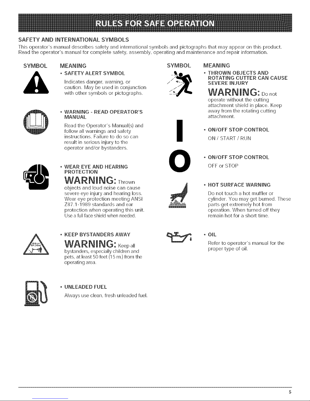
SAFETY AND _NTERNAT_ONAL SYMBOLS
This operator's manual describes safety and international symbols and pictographs that may appear on this product.
Read the operator's manual for complete safety, assembly, operating and maintenance and repair information.
SYMBOL MEANING SYMBOL
SAFETY ALERT SYMBOL •
Indicates danger, warning, or
caution. May be used in conjunction
with other symbols or pictographs.
WARNING - READ OPERATOR'S
MANUAL
Read the Operator's Manual(s) and
follow all warnings and safety
instructions. Failure to do so can
result in serious injury to the
operator and/or bystanders.
WEAR EYE AND HEARING
PROTECTION
I
O
WARNmNG: Thrown
objects and loud noise can cause
severe eye injury and hearing loss.
Wear eye protection meeting ANSI
Z87.1-1989 standards and ear
protection when operating this unit.
Use a full face shield when needed.
iViEAN_NG
THROWN OBJECTS AND
ROTATING CUTTER CAN CAUSE
SEVERE iNJURY
WARNmNG: Donot
operate without the cutting
attachment shield in place. Keep
away from the rotating cutting
attachment.
', ON/OFF STOP CONTROL
ON / START / RUN
,, ONIOFF STOP CONTROL
OFF orSTOP
', HOT SURFACE WARNING
Do not touch a hot muffler or
cylinder. You may get burned. These
parts get extremely hot from
operation. When turned off they
remain hot for a short time.
', KEEP BYSTANDERS AWAY
WARNmNG: Keepa,
bystanders,especiallychildrenand
pets,atleast50 feet(I5 m.)fromthe
operatingarea.
UNLEADED FUEL
Alwaysuse clean,freshunleadedfuel.
', OIL
Refer to operator's manual for the
proper type of oil.
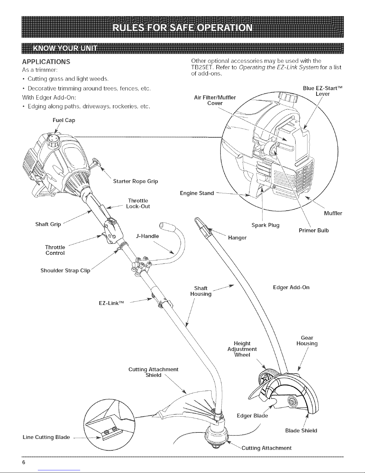
APPUCAT_ONS
As a trimmer:
• Cutting grass and Hightweeds.
• Decorative trimming around trees, fences, etc.
With Edger Add-On:
• Edging along paths, driveways, rockeries, etc.
Fue_ Cap
Starter Rope Grip
Throttle
Lock-Out
Other optionaH accessories may be used with the
TB25ET. Refer to Operating the EZ-Link .System for a Hist
of add-ons.
Air Filter/Muffler
Cover
Engine Stand
Muffler
Shaft Grip
Throttle
Control
Shoulder Strap Clip _
EZ-Link TM
J-Handme
Cutting Attachment
Shield \
Spark Pmug
Hanger
Edger Add-On
Height
Adjustment
Wheel
\
\.
\
Primer Bulb
Gear
Housing
Line Cutting Blade
Edger Blade
/
Blade ShieH
Cutting Attachment
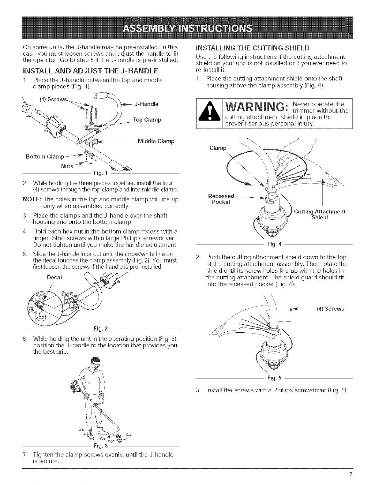
On some units, the J-handle may be preqnstalled. In this
case you must loosen screws and adjust the handle to fit
the operator. Go to step 5 if the J-handle is preqnstalled.
INSTALL AND ADJUST THE J-HANDLE
1. Place the J-handle between the top and middle
clamp pieces (Fig. 1).
INSTALUNG THE CUTTING SHIELD
Use the following instructions if the cutting attachment
shield on your unit is not installed or if you ever need to
re-install it.
1. Place the cutting attachment shield onto the shaft
housing above the clamp assembly (Fig. 4).
(4}
JoHandme
Top Clamp
Middle Clamp
2. While holding the three pieces together, install the four
(4)screws through the top clamp and into middle clamp.
NOTE: The holes in the top and middle clamp will line up
only when assembled correctly.
3. Place the clamps and the J-handle over the shaft
housing and onto the bottom clamp.
4. Hold each hex nut in the bottom clamp recess with a
finger. Start screws with a large Phillips screwdriver.
Do not tighten until you make the handle adjustment,
5. Slide the J-handle in or out until the arrow/white line on
the decal touches the clamp assembly (Fig, 2), You must
first loosen the screws if the handle is pre-installed.
WARNmNG: Neveroperate the
trimmer without the
cutting attachment shield in place to
prevent serious personal injury,
Clamp
Recessed
Pocket
CuttingAttachment
Shield
F_g. 4
2.
Push the cutting attachment shield down to the top
of the cutting attachment assembly. Then rotate the
shield until its screw holes line up with the holes in
the cutting attachment. The shield guard should fit
into the recessed pocket (Fig. 4).
F_g. 2
6. While holding the unit in the operating position (Fig. 3),
position the J-handle to the location that provides you
the best grip.
F_g.3
7.
Tighten the clamp screws evenly, until the J-handle
is secure.
Fig. 5
3. Install the screws with a Phillips screwdriver (Fig. 5).
OraLAND FUEL MmXH_G H_STRUCTmONS
ON and/or improperly mixed fuel are the main reasons
for the unit not running properly. Be sure to use fresh,
cban unleaded fuel. Follow the instructions carefully for
the proper fue%il mixture.
Definition of Bmended Fuels
Today's fueis are often a bbnd of gasoiine and
oxygenates such as ethanol, methanol, or MTBE (ether).
AIcohol-bbnded fuel absorbs water. As littb as 1%
water in the fue[ can make rue[ and oi[ separate, it forms
acids when stored. When using alcohol-bbnded fuel,
use fresh rue[ (Hessthan 60 days oid).
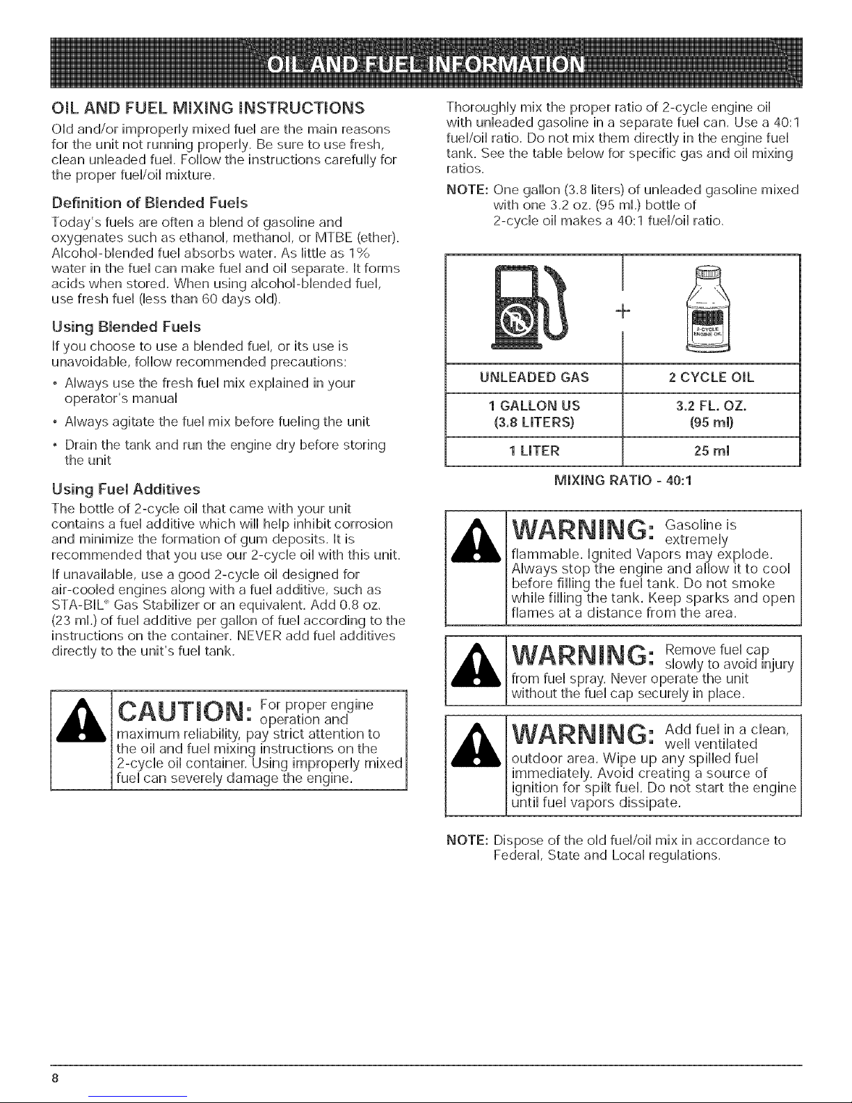
ThorougHy mix the proper ratio of 2-cycb engine oil
with unleaded gasoline in a separate fuel can. Use a 40:1
fuel/oil ratio. Do not mix them directly in the engine fuel
tank. See the table below for specific gas and oil mixing
ratios.
NOTE: One gabn (3.8 liters) of unleaded gasoline mixed
with one 3.2 oz. (95 ml.) bottle of
2-cycb oil makes a 40:1 fuel/oil ratio.
Using Bmended Fuems
if you choose to use a bbnded fuel or its use is
unavoidabb, follow recommended precautions:
• AJways use the fresh fuel mix explained in your
operator's manual
• Always agitate the fuel mix before fueling the unit
, Drain the tank and run the engine dry before storing
the unit
Using FuemAdditives
The bottle of 2-cycb oil that came with your unit
contains a fuel additive which will help inhibit corrosion
and minimize the formation of gum deposits, it is
recommended that you use our 2-cycb oil with this unit.
if unavailable, use a good 2-cycle oil designed for
air-coobd engines along with a fuel additive, such as
STA-B[L" Gas Stabilizer or an equivalent. Add 0.8 oz.
(23 ml.) of fuel additive per gallon of fuel according to the
instructions on the container. NEVER add fuel additives
directly to the unit's fuel tank.
, For proper engine
• operatbn and
maximum reliability, pay strict attentbn to
the oil and fuel mixing instructions on the
2-cycle oil container. Using improperly mixed
fuel can severely damage the engine.
÷
UNLEADED GAS 2 CYCLE OiL
1 GALLON US 3.2FL OZ.
(3.8 LITERS) (95rnm)
1 LITER 25 mm
MiXiNG RATIO - 40:1
WARNING: Gasoline
flammable, ignited Vapors may explode.
Always stop the engine and allow it to cool
the fuel tank. Do not smoke
WARNING: Removefuel cap
from fuel spray. Never operate the unit
without the fuel cap securely in place.
WARNING: Add fuel in a cban,
outdoor area. Wipe up any spilled fuel
extremely
slowly to avoid injury
well ventilated
until fuel vapors dissipate.
NOTE: Dispose of the old fuel/oil mix in accordance to
Federal, State and Local regulations.
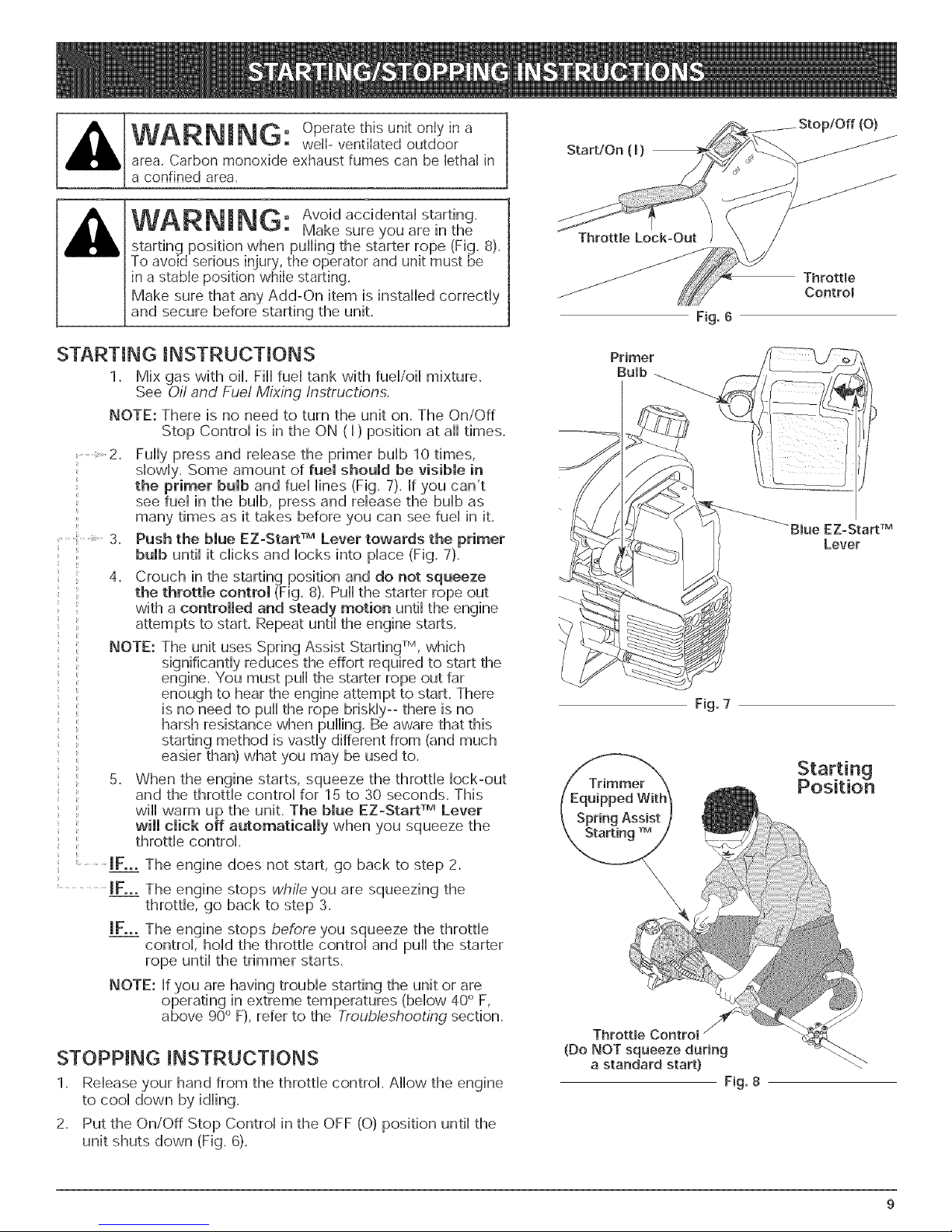
WARNING: Operateth,sunitonly,na
area,Carbon monoxide exhaustfumes can be lethalin
a confinedarea,
well-ventilatedoutdoor
Stop/Off(O)
Start/On ( I)
WARNING: Avoid acddentai starting.
starting position when pulling the starter rope (Fig. 8).
To avoid serious injury, the operator and unit must be
in a stable position while starting.
Make sure that any Add-On item is installed correctly
and secure before starting the unit.
Make sureyou are in the
STARTING iNSTRUCTiONS
1. Mix gas with oil. Fill fuel tank with fueFoii mixture.
See Oil and Fuel Mixing Instructions.
NOTE: There is no need to turn the unit on. The On/Off
Stop Control is in the ON (I) position at all times.
2. Fully press and release the primer bulb 10 times,
slowly. Some amount of fuel should be visible in
: the primer bulb and fuel lines (Fig. 7). [f you can't
, see fuel in the bulb, press and release the bulb as
q
: bulb until it clicks and locks into place (Fig, 7).
...... with a controlled and steady motion until the engine
' ...........JFoooThe engine does not start, go back to step 2.
many times as it takes before you can see fuel in it.
3. Push the blue EZ-Start TM Lever towards the primer
4. Crouch in the starting position and do not squeeze
the throttle control (Fig. 8). Pull the starter rope out
attempts to start. Repeat until the engine starts.
NOTE: The unit uses Spring Assist Starting TM, which
significantly reduces the effort required to start the
engine. You must pull the starter rope out far
enough to hear the engine attempt to start. There
is no need to pull the rope briskly-- there is no
harsh resistance when pulling. Be aware that this
starting method is vastly different from (and much
easier than) what you may be used to.
5. When the engine starts, squeeze the throttle lock-out
and the throttle control for 15 to 30 seconds. This
wiii warm up the unit. The blue EZ-Start TM Lever
will dick off automatically when you squeeze the
throttle control.
JFoooThe engine stops while you are squeezing the
throttle, go back to step 3.
JFoooThe engine stops before you squeeze the throttle
control, hold the throttle control and pull the starter
rope until the trimmer starts.
NOTE: If you are having trouble starting the unit or are
operating in extreme temperatures (below 40° F,
above 90° F), refer to the Troubleshooting section.
ThrottJe
Control
F_g.6
-Blue EZ=Start TM
Lever
\
F_g. 7
STOPPING iNSTRUCTiONS
1. Release your hand from the throttle control. Allow the engine
to cool down by idling.
2. Put the On/Off Stop Control in the OFF (O) position until the
unit shuts down (Fig. 6).
(Do NOT squeeze during
a standard start) _"
Fig. 8
 Loading...