

Page 1
TRnV BILT
Operator's Manual
Rear-tine PTO Tiller Models
E682L--Horse TM
682J--Horse TM
Model 682J Shown
IMPORTANT:READ SAFETY RULES AND INSTRUCTIONS CAREFULLY
Warning: This unit is equipped with an internal combustion engine and should not be used on or near any unimproved forest-covered, brush-
covered or grass-covered land unless the engine's exhaust system is equipped with a spark arrester meeting applicable local or state laws (if any).
If a spark arrester is used, it should be maintained in effective working order by the operator. In the State of California the above is required by law
(Section 4442 of the California Public Resources Code). Other states may have similar laws. Federal laws apply on federal lands. A spark arrester
for the muffler is available by contacting the service department at Troy-Bilt LLC, P.O. Box 361131 Cleveland, Ohio 44136-0019.
TROY-BILT LLC, P.O. BOX 361131, CLEVELAND, OH 44136-0019
PRINTED IN USA FORM NO. 770-10598A
(01/2002)
Page 2
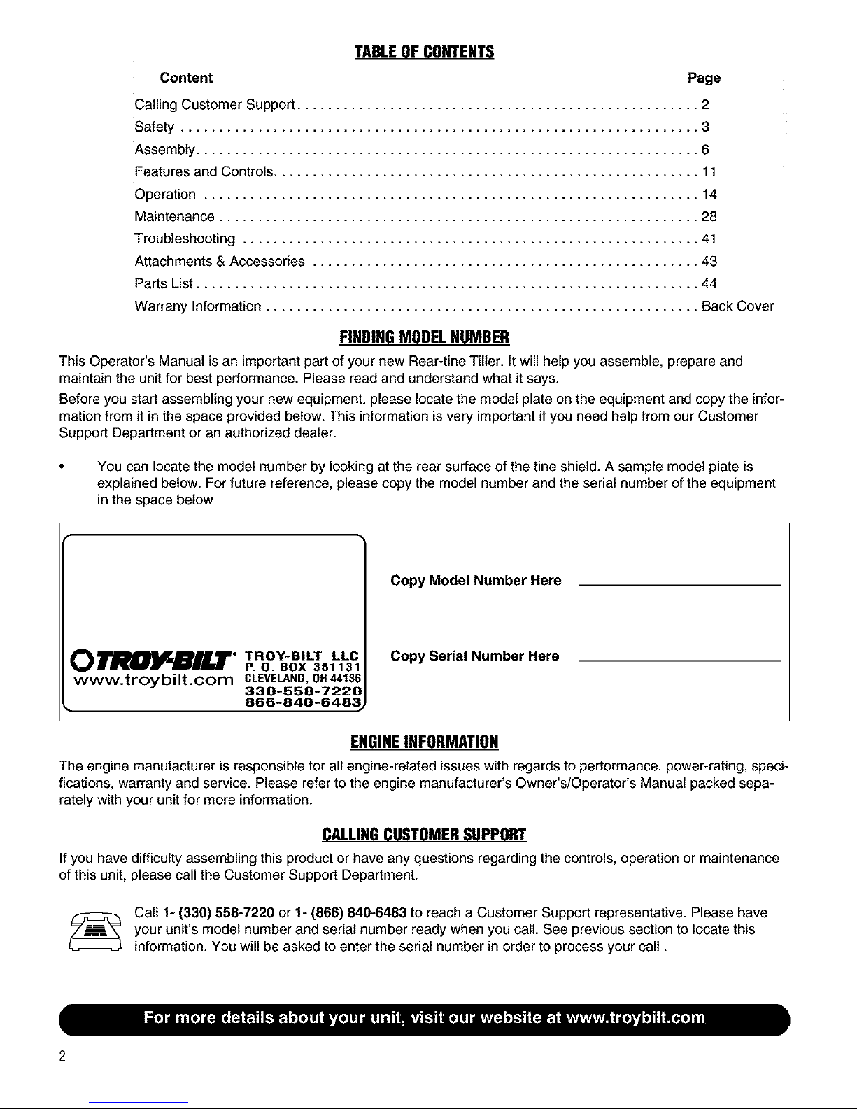
TABLE OF CONTENTS
Content Page
Calling Customer Support .................................................... 2
Safety ................................................................... 3
Assembly ................................................................. 6
Features and Controls ....................................................... 11
Operation ................................................................ 14
Maintenance .............................................................. 28
Troubleshooting ........................................................... 41
Attachments & Accessories .................................................. 43
Parts List ................................................................. 44
Warrany Information ........................................................ Back Cover
FINDING MODEL NUMBER
This Operator's Manual is an important part of your new Rear-tine Tiller. It will help you assemble, prepare and
maintain the unit for best performance. Please read and understand what it says.
Before you start assembling your new equipment, please locate the model plate on the equipment and copy the infor-
mation from it in the space provided below. This information is very important if you need help from our Customer
Support Department or an authorized dealer.
You can locate the model number by looking at the rear surface of the tine shield. A sample model plate is
explained below. For future reference, please copy the model number and the serial number of the equipment
in the space below
Copy Model Number Here
O BILT" TROY-BILT LL(
www.troybilt.com CL_E_ND, OH_136
• 866-840-648_
P. O. BOX 361131
330-558-7220
Copy Serial Number Here
ENGINEINFORMATION
The engine manufacturer is responsible for all engine-related issues with regards to performance, power-rating, speci-
fications, warranty and service. Please refer to the engine manufacturer's Owner's/Operator's Manual packed sepa-
rately with your unit for more information.
CALLINGCUSTOMERSUPPORT
If you have difficulty assembling this product or have any questions regarding the controls, operation or maintenance
of this unit, please call the Customer Support Department.
your unit's model number and serial number ready when you call. See previous section to locate this
Call 1- (330) 558-7220 or 1- (866) 840-6483 to reach a Customer Support representative. Please have
information. You will be asked to enter the serial number in order to process your call.
2
Page 3
n
Safety
SafetyAlert Symbol
,_ This is a safetyalertsymbol. It is used inthis
Failureto obey safety messagescould result in personal
injury or propertydamage.
Training
1. Carefullyreadthis Owner's Manual,the
separateEngineOwner's Manual,and any
other literature you may receive.Bethor-
oughly familiar with the controls and the
proper useof the tiller and itsengine.
Know howto stopthe unit and disengage
the controls quickly.
2. Neverallow children to operatethe
tiller. Neverallow adults to operatethe
tiller without proper instruction.
3. Keepthe areaof operation clearof all
persons, particularly children andpets.
4. Keepin mind that the operator or user
is responsible for accidents or hazards
occurring to other people,their property,
andthemselves.
Preparation
1. Thoroughly inspect theareawherethe
tiller isto beusedand remove all foreign
objects.
2. Putthe Wheels/Tines/PTODrive Lever
into NEUTRALbefore starting theengine.
3. Do not operatethe tiller without
wearingadequate outergarments. Avoid
loose garmentsor jewelry that could get
caught in moving parts.
4. Do not operatethe tiller when barefoot
or wearingsandals,sneakers,or light
footwear. Wear protectivefootwear that
will improve footing on slippery surfaces.
5. Do not till nearunderground electric
cables,telephone lines,pipes or hoses. If
in doubt, contact your telephoneor utility
company.
manualand on the unit to alertyou to
potential hazards. Whenyou seethis symbol,
readand obey the messagethat follows it.
6. Warning:Handlefuel with care; it is
highly flammable andits vapors are
explosive. Besureto takethe following
precautions:
a. Store fuel in containersspecifically
designedfor this purpose.
b. The gascapshall neverbe removed
or fuel addedwhile the engineis
running. Allow the engine to cool
for severalminutes beforeadding
fuel.
c. Keepmatches,cigarettes, cigars,
pipes, openflames,andsparks
awayfrom the fuel tank and fuel
container.
d. Fillfuel tankoutdoors with extreme
care. Neverfill fuel tank indoors.
Usea funnel or spout to prevent
spillage.
e. Replaceall fuel tankand container
caps securely.
f. If fuel is spilled,do not attempt to
start the engine, but move the
machine awayfrom the areaof
spillageand avoid creatingany
source of ignition until fuel vapors
havedissipated.
7. Never makeadjustmentswhen engine
is running (unlessrecommendedby
manufacturer).
Operation
1. Do not put hands or feet nearor under
rotating parts. Donot allow handsor any
other part of the bodyor clothing nearthe
rotating tines or nearanyother moving
part. Thetines beginto rotate forward
This machine meets voluntary safety standard B71.8
- 1996, which is sponsored by the Outdoor Power
Equipment Institute, Inc., and is published by the
American National Standards Institute.
WARNING
Theengineexhaustfromthis productcontains
chemicalsknowntotheStateofCaliforniatocause
cancer, birth defects or other reproductive harm.
oncethe enginestarts, the Tines/PTO
ClutchLever is in the ENGAGEposition,
the Forward Interlock Leversaresqueezed
closedand the Wheels/Tines/PTODrive
Leveris shiftedto FORWARD.Thetines
rotate in Reversewhether the Interlock
Leversare closedor open.
2. Exerciseextreme caution when on or
crossing graveldrives, walks, or roads.
Stayalert for hidden hazardsor traffic. Do
not carry passengers.
3. After striking aforeign object, stop the
engine,removethe wire from the spark
plug wire and preventit from touching the
spark plug. Thoroughly inspectthe
machinefor anydamage and repairthe
damagebefore restarting and operating
the machine.
4. Exercisecaution to avoid slipping or
falling.
5. If the unit should start to vibrate abnor-
mally,stop the engine, disconnectthe
spark plugwire and preventit from
touching the spark plug, and check imme-
diatelyfor the cause.Vibration is
generallya warning of trouble.
6. Stopthe engine,disconnect the spark
plug wire and preventit from touching the
spark plugwheneveryou leavethe
operatingposition, before unclogging the
tines, or when making any repairs,adjust-
ments or inspections.
7. Takeall possible precautionswhen
leavingmachine unattended.Stopengine.
Disconnectspark plug wire and move it
away from spark plug. Removeignition
keyon electric start models
Page 4
Section1: Safety
8. Beforecleaning, repairing, or inspect-
ing, stop the engine and make certain all
moving parts havestopped. Disconnect
the spark plug wire and prevent it from
touching thespark plugto preventacci-
dentalstarting.
9. Theflap onthe tine hood must be
down when operatingthetiller, unless
using the Hiller/Furrowerattachment.
10. Neverusethe tiller unlessproper
guards, plates,or other safety protective
devicesare in place.
11. Donot runenginein anenclosed
area.Engineexhaustcontains carbon
monoxide gas,adeadlypoison that is
odorless, colorless, and tasteless.
12. Keepchildren and pets away.
13. Neveroperatethe tiller underengine
power if the WheelSpeedLeveris in the
FREEWHEELposition. In FREEWHEEL,
thewheels will not hold the tiller backand
the revolving tines could propel thetiller
rapidly, possibly causing lossof control.
Alwaysengagethe Wheel SpeedLeverin
either FASTor SLOWposition before
starting the engineor engaging thetines
with theWheels/Tines/PTODrive Lever.
14. Beaware thatthe tiller mayunex-
pectedlybounceupwardor jump
forwardifthe tines shouldstrike
extremelyhardpackedsoil, frozen
ground,or buried obstacleslike large
stones,roots, orstumps. If in doubt
aboutthe tilling conditions,alwaysuse
thefollowingoperatingprecautionsto
assistyouin maintainingcontrolofthe
tiller:
a. Walk behindandto oneside of the
tiller, usingonehandonthe han-
dlebars.Relax yourarm, butusea
securehandgrip.
b. Use shallowerdepthregulator
settings,workinggraduallydeeper
with eachpass.
c. Use slowerwheel, tine and engine
speeds.
d. Clearthe tilling areaof all large
stones,rootsand otherdebris.
e. Avoidusingdownwardpressureon
handlebars.If needbe, useslight
upwardpressureto keepthe tines
fromdiggingtoo deeply.
f. Beforecontactinghardpackedsoil
at the endof arow, reduceengine
speedand lift handlebarsto raise
tines outofthe soil.
g. In an emergency,stoptines and
wheels byshiftingthe
Wheels/Tines/PTODriveLever
intoNEUTRAL.If youcan not
reachthe lever or havelostcontrol
ofthe tiller, let go of thehandle-
barsand all controls. Do not
attemptto restrainthetiller.
15. Do not overloadthe tiller's capacity by
attempting to till too deeply at too fast a
rate.
16. Never operatethe tiller at high
transport speedson hardorslippery
surfaces. Look behindand usecare when
backing up.
17. Do not operatethe tiller on aslope
that is too steep for safety. When on
slopes, slow downand makesure you
havegood footing. Never permit the tiller
to freewheel down slopes.
18. Neverallow bystandersnear the unit.
19. Onlyuse attachments andaccessories
that areapproved bythe manufacturerof
the tiller.
20. Usetiller attachments and acces-
sories when recommended.
21. Never operatethe tiller without good
visibility or light.
22. Never operatethe tiller if you are
tired, or under the influenceof alcohol,
drugs or medication.
23. Operatorsshall nottamper with the
engine-governorsettings on the machine;
the governor controls the maximum safe
operating speedto protect the engineand
all moving parts from damagecaused by
overspeed. Authorized serviceshall be
sought if a problem exists.
24. Do not touch engineparts which may
be hot from operation. Let parts cool
down sufficiently.
25. POISON/DANGER--CAUSES
SEVEREBURNS.The batteryon electric
start models contains sulfuric acid. Avoid
contact with skin, eyesor clothing. Keep
out of reach of children.
Antidotes:
External- Flushimmediately with lots of
water.
Internal- Drink largequantities of water
or milk. Followwith milk of magnesia,
beateneggs orvegetableoil. Calla
doctor immediately.
Eyes- Flushwith water for 15 minutes.
Getprompt medical attention.
26. DANGER-BATTERIESPRODUCE
EXPLOSIVEGASES. Keepsparks,flame
or smoking materialsaway. Ventilate
when charging battery or using inan
enclosed space. Alwayswear safety
goggles when working near battery.
27. Pleaseremember:You canalways
stop the tines andwheelsby releasingall
controls, or by moving the ignition switch
and/or throttle control leveronthe engine
to OFFor STOP.
28. To load or unloadthe tiller, seethe
instructions in Section 4 of this Manual.
29. Useextremecautionwhen backingor
pulling the machinetowards you.
30. Startthe enginecarefully accordingto
instructions and with feet well awayfrom
the tines.
31. Neverpick upor carry a machine
while the engineis running.
32. When loading or unloadingthe tiller,
alwaysdisengage tinesand use slower
wheel and enginethrottle speeds. Use
sturdy ramps wide and strong enoughto
easily support the tiller (280-to-325 Ibs.,
depending on model) andoperator.
Nevergo down ramps in FORWARD
drive--the tiller could tip forward,
exposing you to the tines (which should
be disengaged). Alwaysuse REVERSE
drive and backdown ramps. Togo up
ramps, useFORWARDdrive and follow
the tiller.
33. TheForward Interlock SafetySystem
should betested for correct functioning
every time thetiller or PTOpowerunit is
used. SeeSection 4 in this Manual.
34. If using the optional Dozer Blade,
either removethe tine attachment,or
disengagethe tineswith the Tines/PTO
ClutchLever. Revolvingtines are
dangerous.
Page 5
Section1: Safety
MaintenanceandStorage
1. Keepthe tiller, attachmentsandacces-
sories insafe working condition.
2. Checkall nuts, bolts, andscrews at
frequent intervalsfor proper tightness to
be surethe equipment is insafe working
condition.
3. Neverstore the tiller with fuel in the
fuel tank insidea building where ignition
sources are presentsuch ashot water
and spaceheaters,furnaces, clothes
dryers, stoves, electric motors, etc.).
Allow engine to cool beforestoring in any
enclosure.
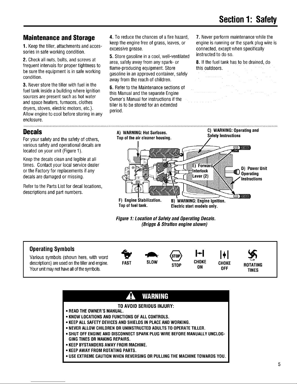
Decals
Foryour safetyand the safetyof others,
various safetyand operational decalsare
located onyour unit (Figure 1).
Keepthe decalscleanandlegibleat all
times. Contactyour local servicedealer
or the Factoryfor replacementsif any
decalsare damagedor missing.
4. To reducethe chancesof afire hazard,
keepthe enginefree of grass, leaves, or
excessivegrease.
5. Store gasolinein acool, well-ventilated
area,safely awayfrom any spark-or
flame-producing equipment. Store
gasolinein an approvedcontainer, safely
away from the reachof children.
6. Referto the Maintenancesections of
this Manualand the separateEngine
Owner's Manualfor instructions if the
tiller is to be stored for an extended
period.
A) WARNING:HotSurfaces.
Topoftheaircleanerhousing. SafetyInstructions
7. Neverperform maintenancewhile the
engine is running orthe spark plugwire is
connected, exceptwhen specifically
instructed to do so.
8. If thefuel tank hasto bedrained,do
this outdoors.
C) WARNING:Operatingand
D) PowerUnit
Referto the Parts List for decal locations,
descriptions andpart numbers.
OperatingSymbols
Varioussymbols (shown here,with word
descriptions)areusedonthetillerandengine.
Yourunitmaynothaveallofthesymbols.
• READTHEOWNER'SMANUAL.
• KNOWLOCATIONSANDFUNCTIONSOFALL CONTROLS.
• KEEPALL SAFETYDEVICESANDSHIELDSIN PLACEANDWORKING.
• NEVERALLOWCHILDRENORUNINSTRUCTEDADULTSTO OPERATETILLER.
• SHUTOFFENGINEANDDISCONNECTSPARKPLUGWIRE BEFOREMANUALLYUNCLOG-
GINGTINES ORMAKINGREPAIRS.
• KEEPBYSTANDERSAWAYFROM MACHINE.
• KEEPAWAYFROMROTATINGPARTS.
• USEEXTREMECAUTIONWHENREVERSINGORPULLINGTHE MACHINETOWARDSYOU.
F) EngineStabilization.
Topof fueltank.
Figure1:LocationofSafetyand OperatingDecals.
(Briggs& Stratton engineshown)
B) WARNING:EngineIgnition.
Electricstartmodelsonly.
I I I÷I
FAST SLOW CHOKE CHOKE
STOP ON OFF
TO AVOID SERIOUS INJURY:
ROTATING
TINES
Page 6

I1
Assembly
To prevent personal injury or property
damage, do not start the engine until
all assembly steps are complete and
you have read and understand the
safety and operatinginstructionsin this
manual.
Introduction
Carefullyfollow these assembly stepsto
correctly prepareyour tiller for use. It is
recommendedthat you readthis Section
in its entirety beforebeginning assembly.
NOTE:Varioustiller models are presented
in this Manual. Useonly the information
appropriatefor your tiller model.
InspectUnit
Inspectthe unitand carton for damage
immediately after delivery. Contactthe
carrier (trucking company) if you find or
suspect damage. Inform them of the
damageand request instructions for filing
a claim. To protectyour rights, put your
claim inwriting and mail acopy to the
carrier within 15 days after the unit has
beendelivered. Contactusat the Factory
if you needassistance inthis matter.
STEP1: UnpackingInstructions
NOTE:Do not severelybendany of the
control cableson the unit.
1. Thetiller is heavy. Do not attemptto
remove it from the shipping platform until
instructed to do so in theseAssembly
steps.
2. Removeall unassembledpartsfrom
the carton. Thehardwarebag is included
in your literature packaging.
3. Checkthat you havethe items listed
below (contact your local dealeror the
Factory if any items are missing or
damaged).
NOTE: Usethe screw lengthtemplate
(Figure2-1) to identify screws.
LoosePartsList
Qty. Description
1 HandlebarAssembly
1 Wheels/TinesPTODriveLever
Thefollowing items
are in the hardwarebag:
2 20 oz.Bottles SAE30W Oil
1 Clutch PawlSpring
1 BeltAdjusting Tool
2 PlasticCableTies
1 CurvedHeadScrew, 1/4-20 x 2
1 FlangedLock Nut, 1/4-20
1 PanHeadScrew,#10-32 x 1/2
Thefollowing parts (electric start models
only), packagedseparately.
2 Nuts,1/4-20
(for battery terminals)
2 Screws,1/4-20 x 5/8
(for battery terminals)
2 Keys
(in ignition switch)
NOTE:LEFTand RIGHTsides of the
tiller are as viewed from the
operator's position behind the han-
dlebars(unless otherwise noted).
Tools]MaterialsNeeded
for Assembly
(1) 3/8" open-endwrench*
(2) 7/16"open-end wrench*
(2) 1/2" open-endwrench*
(1) 9/16"open-end wrench*
(1) 3/4"open-end wrench*
(1) Flatblade screwdriver
(1) Scissors (to trim plastic ties)
(1) Tire pressuregauge
(1) 4-1/2" highwood block to prop unit
* Adjustable wrenchesmay be used.
Figure2-1: Toidentifylengthofscrew,
placescrewontemplateasshownand
measuredistancebetweenbottomofscrew
headandtipofscrew.
STEP 2: Attach Handlebar
IMPORTANT: When disassembling
handlebar assembly, keep left-side clamp
and ratchet separatedfrom the right-side
clamp andratchet.
1. Disassemblethe handlebarassembly.
To do this, remove the height adjustment
leverby turning the leverin a counter-
clockwise direction (Figure2-2).
2. Placethe handlebarendson either side
ofthe base,with thewire harnesstoward
the rear ofthe base(Figure2-2).
3. Installthe heightadjustment lever
through the right-side clamp, handlebar
end, ratchet, and base;then out through
the left-side ratchet, handlebarend,and
clamp (Figure2-2). Securewith nut, but
don't fully tighten.
IMPORTANT:Do notforce the height
adjustment leverthrough the handlebars.
The interlock wires may be blocking the
leverand could bedamaged.You may
gently movethe wiresaside if this
condition occurs.
6
Page 7
Section2: Assembly
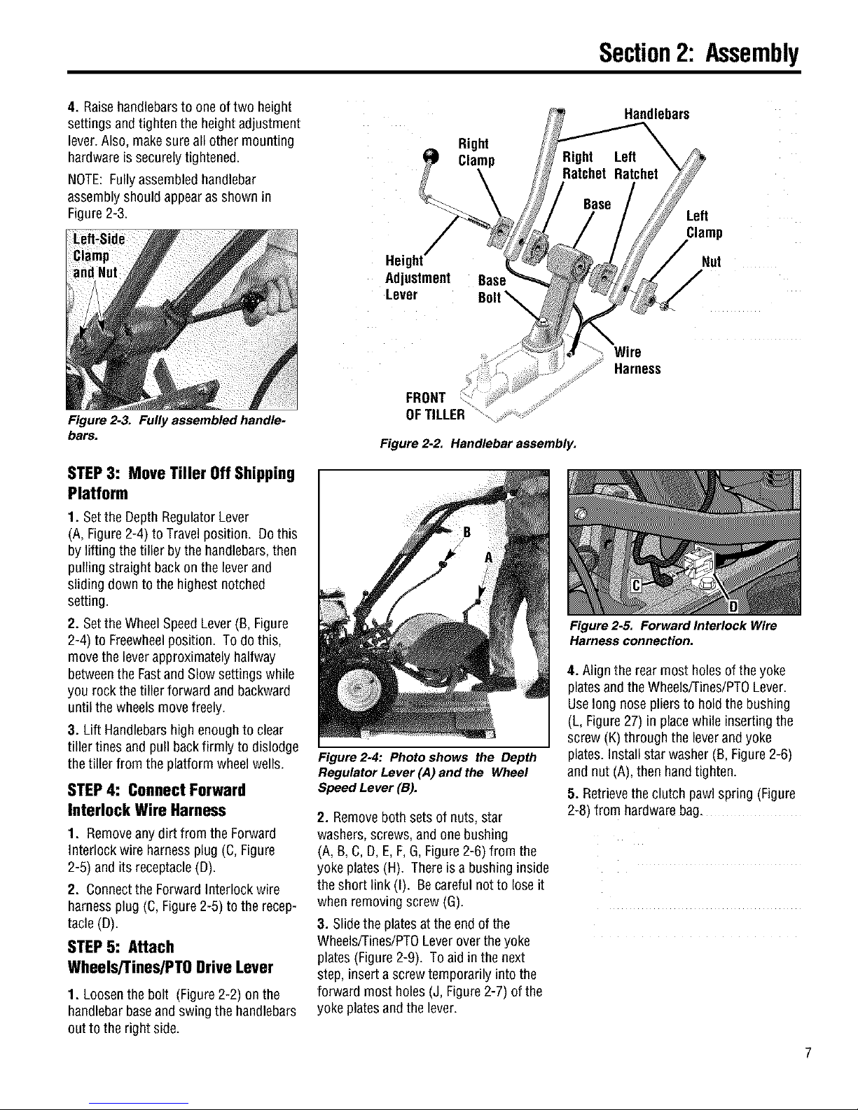
4. Raisehandlebarsto oneof two height
settings andtighten the heightadjustment
lever. Also, makesure all other mounting
hardware issecurely tightened.
NOTE: Fully assembledhandlebar
assembly should appearas shown in
Figure2-3.
Figure 2-3. Fully assembled handle-
bars.
STEP3: MoveTiller OffShipping
Platform
1. Setthe DepthRegulatorLever
(A, Figure2-4) to Travel position. Dothis
by lifting the tiller by the handlebars,then
pulling straight backonthe leverand
sliding down to the highest notched
setting.
2. Setthe WheelSpeedLever(B, Figure
2-4) to Freewheelposition. To do this,
move the leverapproximately halfway
betweenthe Fastand Slow settings while
you rock the tiller forward andbackward
until thewheels movefreely.
3. Lift Handlebarshighenoughto clear
tiller tines and pull backfirmly to dislodge
the tiller from the platform wheel wells.
STEP4: ConnectForward
InterlockWire Harness
1. Removeany dirt fromthe Forward
Interlock wire harnessplug (C, Figure
2-5) andits receptacle(D).
2. Connect the Forward interlock wire
harness plug (C,Figure2-5) to the recep-
tacle (D).
STEP5: Attach
WheelsiTines/PTODriveLever
1. Loosenthe bolt (Figure2-2) on the
handlebar baseand swing the handlebars
out to the right side.
Right
Clam
Height
Adjustment
Lever
FRONT
OFTILLER
Figure 2-2. Handlebar assembly.
Figure 2-4: Photo shows the Depth
Regulator Lever (A) and the Wheel
Speed Lever (B).
2. Removeboth sets of nuts, star
washers, screws, and one bushing
(A, B, C,D, E,F,G,Figure2-6) from the
yoke plates(H). There is a bushing inside
the short link (I). Becareful not to loseit
when removing screw (G).
3. Slidethe platesat the endof the
Wheels/Tines/PTOLeveroverthe yoke
plates (Figure2-9). To aid in the next
step, insert a screwtemporarily into the
forward most holes (J, Figure2-7) of the
yoke platesandthe lever.
Base
Handlebam
Base
Left
Clamp
Nut
Wire
Harness
Figure 2-5. Forward Interlock Wire
Harness connection.
4. Align the rear most holes of theyoke
platesand the Wheels/Tines/PTOLever.
Uselong nose pliersto hold the bushing
(L, Figure27) in placewhile insertingthe
screw (K)through the leverand yoke
plates.Install star washer (B, Figure2-6)
and nut (A),then handtighten.
5. Retrievethe clutch pawl spring (Figure
2-8) from hardware bag.
Page 8
Section2: Assembly
Removethe temporary screw (J, Figure
2-7) from the forward holes andmove the
Wheels/Tines/PTOLeverfully forward.
Install the wider hook end of the clutch
pawl spring (M, Figure2-8) down into the
small holeat the end of the handle. Use
pliers to insert the other endinto the hole
in the long link bar (N).
NOTE:Do not bend or over stretch the
spring while installing.
6. Pull the Wheels/Tines/PTOLeverback
to align the forward most holes (Q,Figure
2-9) inthe yoke platewith the holes in the
lever plates. Also alignthe bushing that is
insidethe short link bar (P). Install the
screw, starwasher, and nut, then tighten
securely.
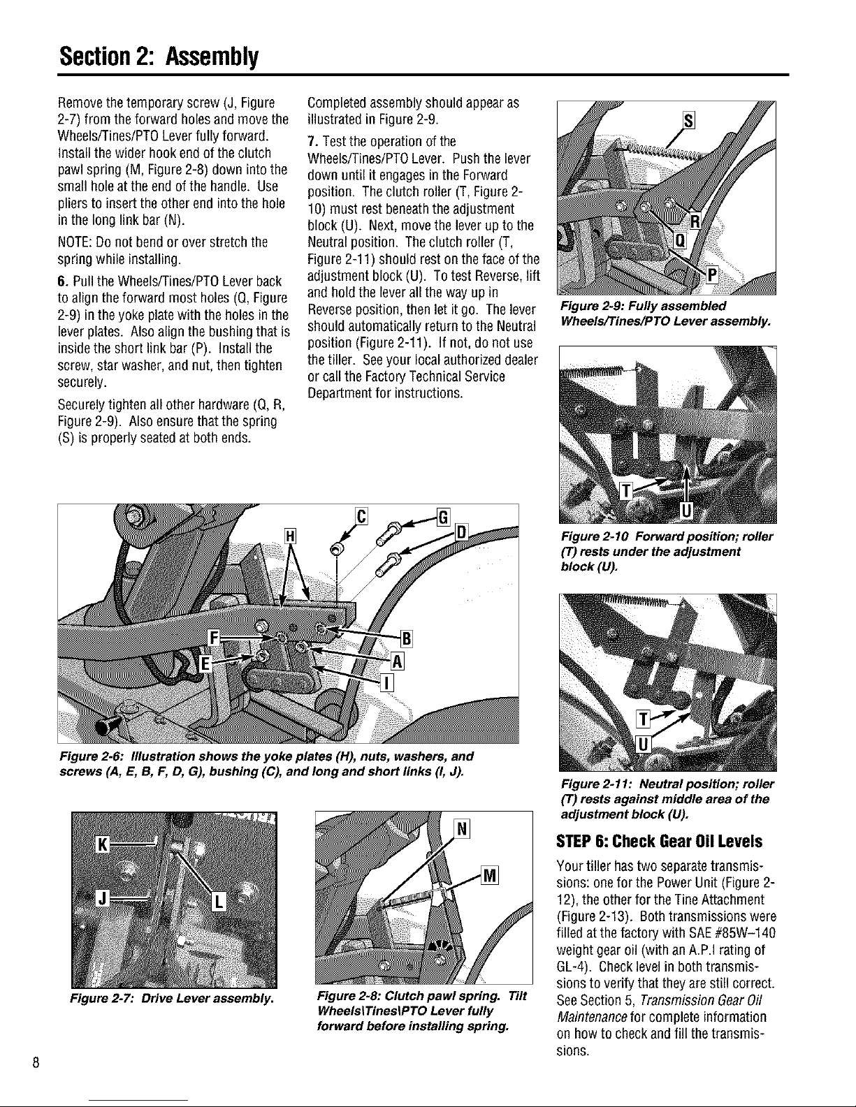
Securelytighten allother hardware(Q,R,
Figure2-9). Alsoensure that the spring
(S) is properly seatedat both ends.
Completedassembly should appearas
illustrated in Figure2-9.
7. Testthe operation of the
Wheels/Tines/PTOLever. Pushthe lever
down until it engages in the Forward
position. The clutch roller (T, Figure2-
10) must rest beneaththe adjustment
block (U). Next,move the lever upto the
Neutral position. Theclutch roller (T,
Figure2-11) should rest on theface of the
adjustment block (U). To test Reverse,lift
and holdthe leverall the way up in
Reverseposition, then let it go. Thelever
should automatically return to the Neutral
position (Figure2-11). If not, do not use
the tiller. Seeyour localauthorized dealer
or call the FactoryTechnicalService
Departmentfor instructions.
Figure 2-9: Fully assembled
Wheels/Tines/PTO Lever assembly.
Figure 2-6: Illustration shows the yoke plates (H), nuts, washers, and
screws (A, E, B, F, D, G), bushing (C), and long and short links (I, J).
Figure 2-7: Drive Lever assembly.
Figure 2-8: Clutch pawl spring. Tilt
WheelsiTinesiPTO Lever fully
forward before installing spring.
Figure 2-10 Forward position; roller
(T) rests under the adjustment
block (U).
Figure 2-11: Neutral position; roller
(7) rests against middle area of the
adjustment block (U).
STEP6: CheckGearOilLevels
Your tiller hastwo separatetransmis-
sions: one for the PowerUnit (Figure 2-
12), the otherfor the Tine Attachment
(Figure2-13). Both transmissions were
filled atthe factory with SAE#85W-140
weight gearoil (with anA.P.I rating of
GL-4). Checklevelin both transmis-
sions to verify that they are still correct.
SeeSection 5, TransmissionGearOil
Maintenancefor complete information
on howto check andfill the transmis-
sions.
Page 9
Section2: Assembly
IMPORTANT: Checkgearoil level in both
transmissions after the first 2 hours of
new tiller operation, then every 30
operating hours thereafter. SeeSection 5
for instructions.
OilLevel Hole
Figure 2-12: Checking oil level on
Power Unit Transmission.
Figure 2-13: Checking oil level on
Tine Attachment Transmission.
STEP7: AddMotor0il to Engine
1. Beforeadding motor oil, park thetiller
on levelground. Levelthe engineby
placinga sturdy block under thetines or
the tines depth regulator bar.
2. Referto the EngineOwner's Manual
provided with your tiller for detailed infor-
mation onhow to add motor oil andfor
motor oil specifications.
IMPORTANT:Two 20 oz. bottles of motor
oil are included with your tiller. Checkthe
oil level as instructed in the Engine
Owner's Manual provided with your tiller
BEFOREpouring the full amount of each
bottle into the engine.
IMPORTANT:
• Change engine oil after first 2 hours of
newoperation.
• Check engine oil levelevery 5 hours of
operation or eachuse.
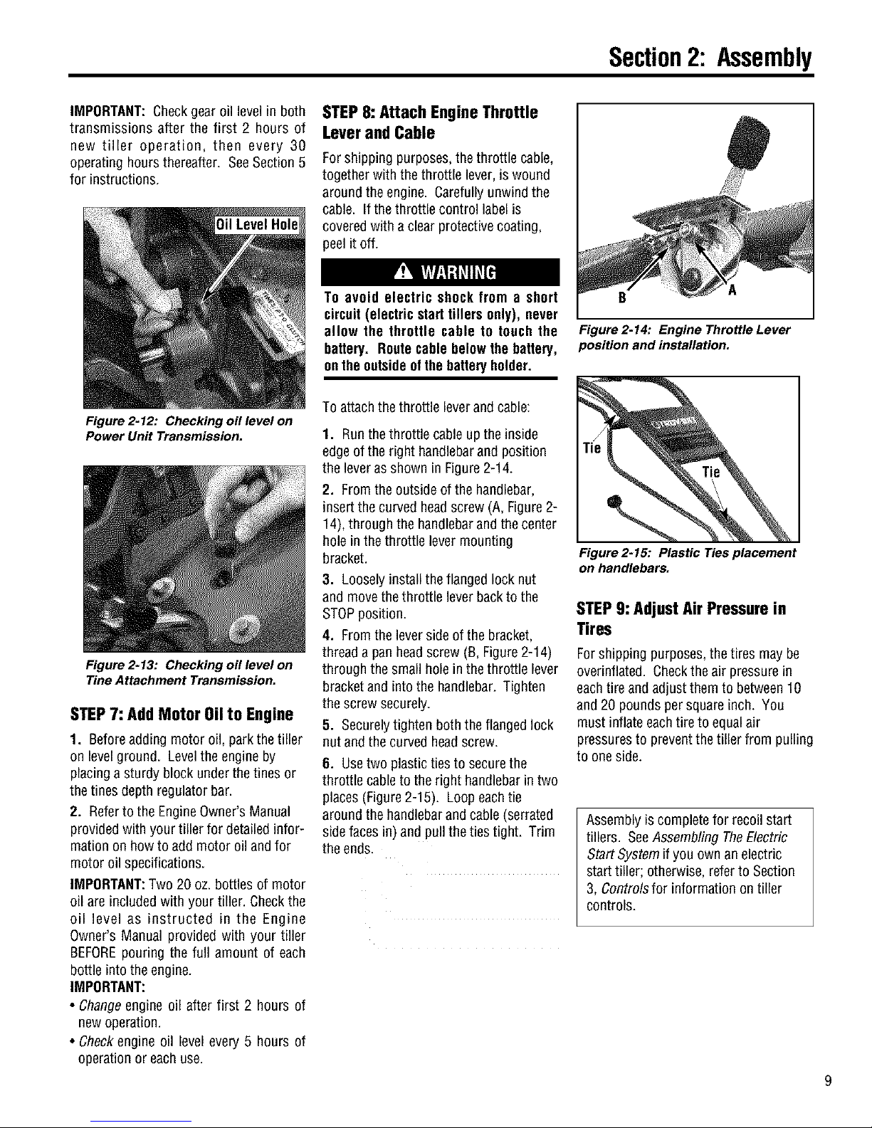
STEP8: AttachEngineThrottle
LeverandCable
Forshipping purposes, the throttle cable,
together with the throttle lever, is wound
around the engine. Carefully unwindthe
cable. If the throttle control label is
coveredwith a clear protectivecoating,
peel it off.
To avoid electric shock from a short
circuit (electric starttillers only), never
allow the throttle cable to touch the
battery. Routecable belowthe battery,
onthe outsideof thebatteryholder.
To attachthe throttle leverandcable:
1. Runthethrottle cableup the inside
edge of the right handlebarand position
the leverasshown in Figure2-14.
2. Fromthe outside of the handlebar,
insert the curved headscrew (A, Figure 2-
14), through the handlebarand the center
hole inthe throttle levermounting
bracket.
3. Looselyinstallthe flanged lock nut
and movethe throttle leverbackto the
STOPposition.
4. Fromthe lever side of the bracket,
threada pan headscrew (B, Figure2-14)
through the small hole in the throttle lever
bracketand intothe handlebar. Tighten
the screw securely.
5. Securelytighten boththe flanged lock
nut and the curved headscrew.
6. Usetwo plastic tiesto securethe
throttlecableto the right handlebarin two
places (Figure2-15). Loop eachtie
around the handlebarand cable (serrated
sidefaces in) and pull the ties tight. Trim
the ends.
B
Figure2-14: Engine ThrottleLever
position and installation.
Figure 2-15: Plastic Ties placement
on handlebars.
STEP9: Adjust Air Pressure in
Tires
Forshipping purposes,the tires may be
overinflated. Checkthe air pressurein
eachtire andadjust them to between10
and 20 pounds persquare inch. You
must inflate eachtire to equalair
pressuresto preventthe tiller from pulling
to one side.
Assembly is complete for recoilstart
tillers. SeeAssembling TheElectric
Start Systemif you own anelectric
start tiller; otherwise, refer to Section
3, Controlsfor information on tiller
controls.
Page 10
Section2: Assembly
ASSEMBLINGTHEELECTRICSTARTSYSTEM
Thefollowing steps explain howto install and chargethe batteryon electric start tillers. For your safety,follow all steps and observe
all accompanyingsafety messages. Section 5 contains othergeneralbattery maintenanceand recharginginstructions.
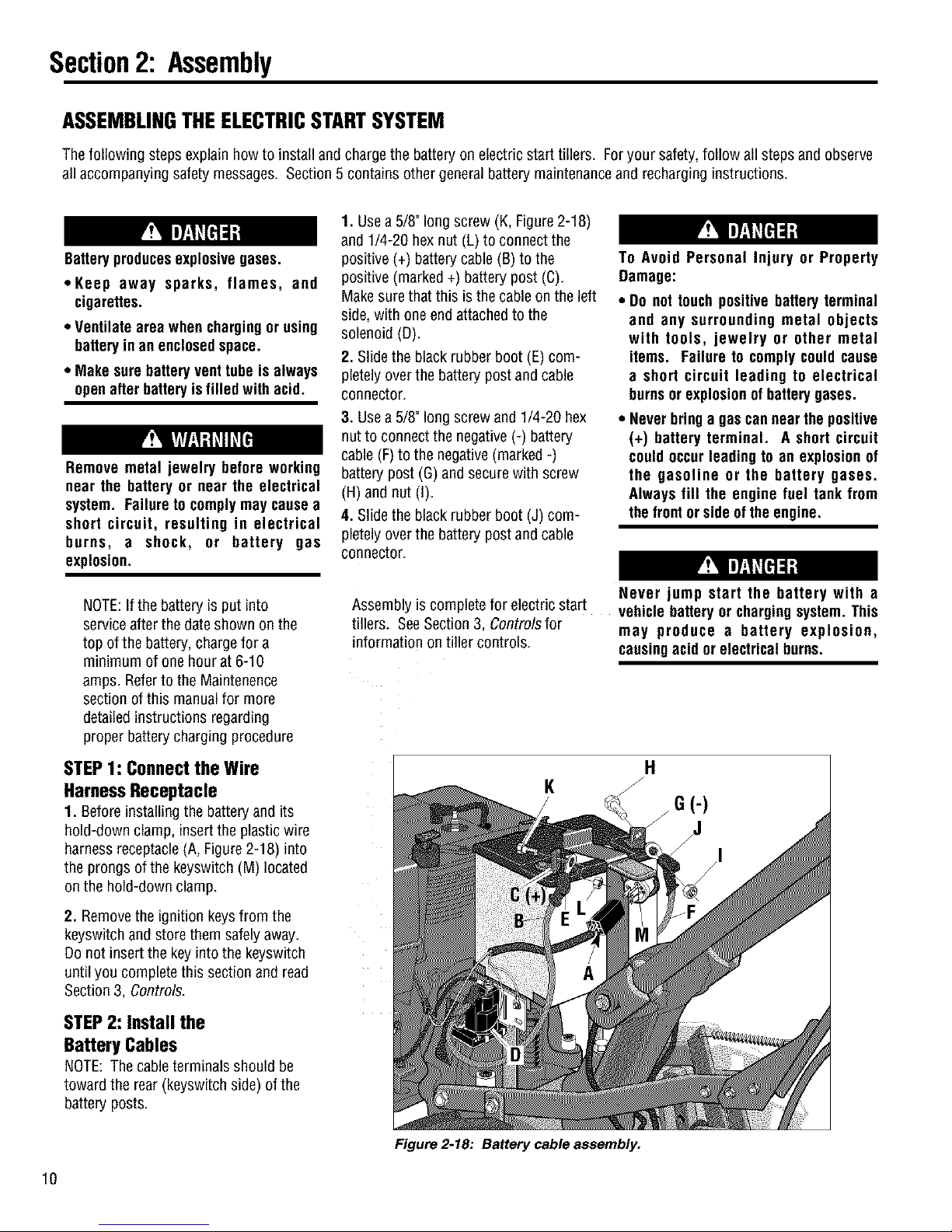
1. Usea 5/8" long screw (K,Figure2-18)
and 1/4-20 hexnut (L) to connect the
Batteryproducesexplosivegases.
*Keep away sparks, flames, and
cigarettes.
. Ventilate area whenchargingor using
batteryin anenclosedspace.
. Make surebatteryvent tube is always
openafter batteryis filled with acid.
Remove metal jewelry before working
near the battery or near the electrical
system. Failureto complymay cause a
short circuit, resulting in electrical
burns, a shock, or battery gas
explosion.
positive (+) batterycable(B)to the
positive (marked +) battery post (C).
Make surethat this is the cableonthe left
side, with oneend attachedto the
solenoid (D).
2. Slidethe black rubber boot (E) com-
pletely over the battery postandcable
connector.
3. Usea 5/8" long screw and 1/4-20 hex
nut to connect the negative (-) battery
cable (F)to the negative(marked -)
battery post (G) andsecurewith screw
(H) and nut (I).
4. Slidethe black rubber boot (J) com-
pletely over the battery postandcable
connector.
To Avoid Personal Injury or Property
Damage:
* Do not touch positive batteryterminal
and any surrounding metal objects
with tools, jewelry or other metal
items. Failure to complycould cause
a short circuit leading to electrical
burnsor explosionof batterygases.
* Neverbringa gascannearthe positive
(+) battery terminal. A short circuit
could occurleading to an explosionof
the gasoline or the battery gases.
Always fill the engine fuel tank from
thefront or sideof theengine.
NOTE:Ifthe battery is put into
serviceafter the dateshown onthe
top of the battery, chargefor a
minimum of one hour at 6-10
amps. Referto the Maintenence
section of this manualfor more
detailedinstructions regarding
proper batterycharging procedure
STEP1: Connectthe Wire
HarnessReceptacle
1. Beforeinstalling the battery and its
hold-down clamp, insert the plastic wire
harness receptacle(A, Figure2-18) into
the prongs of the keyswitch (M)located
on the hold-down clamp.
2. Removethe ignition keysfrom the
keyswitch andstore them safely away.
Do not insertthe key into the keyswitch
until you complete this section andread
Section 3, Controls.
STEP 2: Install the
BatteryCables
NOTE:The cableterminals should be
toward the rear (keyswitchside) of the
battery posts.
Assembly is complete for electric start
tillers. SeeSection 3, Controlsfor
information on tiller controls.
K
Never jump start the battery with a
vehicle battery or chargingsystem. This
may produce a battery explosion,
causingacid orelectrical burns.
G(-)
J
10
Figure 2-18: Battery cable assembly.
Page 11
n
FeaturesandControls
Before operating your machine,
carefully read and understand all
safety, controls, operating instructions
in this Manual, the separate Engine
Owner's Manual and on the decals on
themachine.
Failure to follow these instructionscan
resultin seriouspersonalinjury.
Introduction
This section describesthe location and
function of the controls and features on
your tiller. Referto Section 4, Operation
for detailedoperating instructions.
Practice usingthesecontrols, with the
engine shut off, until you completely
understand the operation of the controls
and feelconfident with eachof them.
IMPORTANT:Referto the separateengine
manufacturer's Engine Owner's Manual
for information about the controls on the
engine.
NOTE:All referencesto left,right, front
and rearof themachineare basedon a
position behindthe handlebarsandfacing
forward.
PTOAttachmentsFeature
In addition to powerfultilling capability,
you canquickly convert your machine
into a PTO(Power Take-Off)PowerUnit
that iscapableof towing or powering
various TROY-BILTattachments.
You canaccessthis capability by
removing the tines attachment (powered
by the PTOPower Unit). The PTOPower
Unit isthen availablefor engine powered
attachments,or for pulling ortowing non-
poweredattachments. SeeSection 4,
PTOPower Unitfor detailedinformation
on installingand operating TROY-BILT
PTOattachments.
WheelsiTines/PTODriveLever
Usethe Wheels/Tines/PTODriveLever(A,
Figure3-1) to engageand disengage
powerto the transmission.
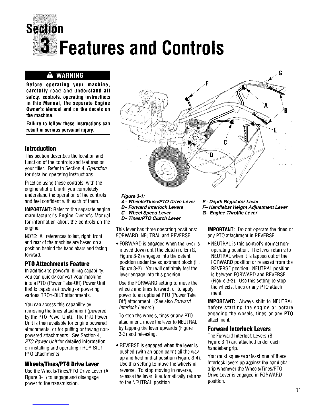
Figure 3-1:
A- Wheels/Tines/PTO Drive Lever
B- Forward Interlock Levers
C- Wheel Speed Lever
D- Tines/PTO Clutch Lever
This leverhasthree operatingpositions:
FORWARD,NEUTRALand REVERSE.
FORWARDisengagedwhen the leveris
moved down until the clutch roller (G,
Figure3-2) engagesinto the detent
position underthe adjustment block (H,
Figure3-2). You will definitely feelthe
leverengageinto this position.
Usethe FORWARDsetting to movethe
wheels andtines forward, orto apply
power to anoptional PTO(PowerTake
Off) attachment. (Seealso Forward
Interlock Levers.)
To stop the wheels, tines orany PTO
attachment,movetheleverto NEUTRAL
by tapping the leverupwards (Figure
3-3) and releasing.
• REVERSEis engagedwhen the lever is
pushed(with an openpalm)all the way
up and heldin that position (Figure3-4).
Usethis setting to movethe wheels in
reverse. To stop moving inreverse,
releasethe lever;it automatically returns
to the NEUTRALposition.
zG
E- Depth Regulator Lever
F- Handlebar Height Adjustment Lever
G- Engine Throttle Lever
IMPORTANT: Do not operatethe tines or
any PTOattachment in REVERSE.
• NEUTRALis this control's normal non-
operating position. Thelever returns to
NEUTRALwhen it is tappedout of the
FORWARDposition or releasedfrom the
REVERSEposition. NEUTRALposition
is betweenFORWARDand REVERSE
(Figure3-3). Usethis setting to stop
the wheels,tinesor any PTOattach-
ment.
IMPORTANT: Always shift to NEUTRAL
before starting the engine or before
engaging the wheels, tines or any PTO
attachment.
Forward Interlock Levers
The Forward Interlock Levers (B,
Figure3-1) are attachedundereach
handlebargrip.
You must squeezeat least one of these
interlock levers up against the handlebar
grip wheneverthe Wheels/Tines/PTO
Drive Leveris engagedin FORWARD
position.
11
Page 12
Section3: FeaturesandControls
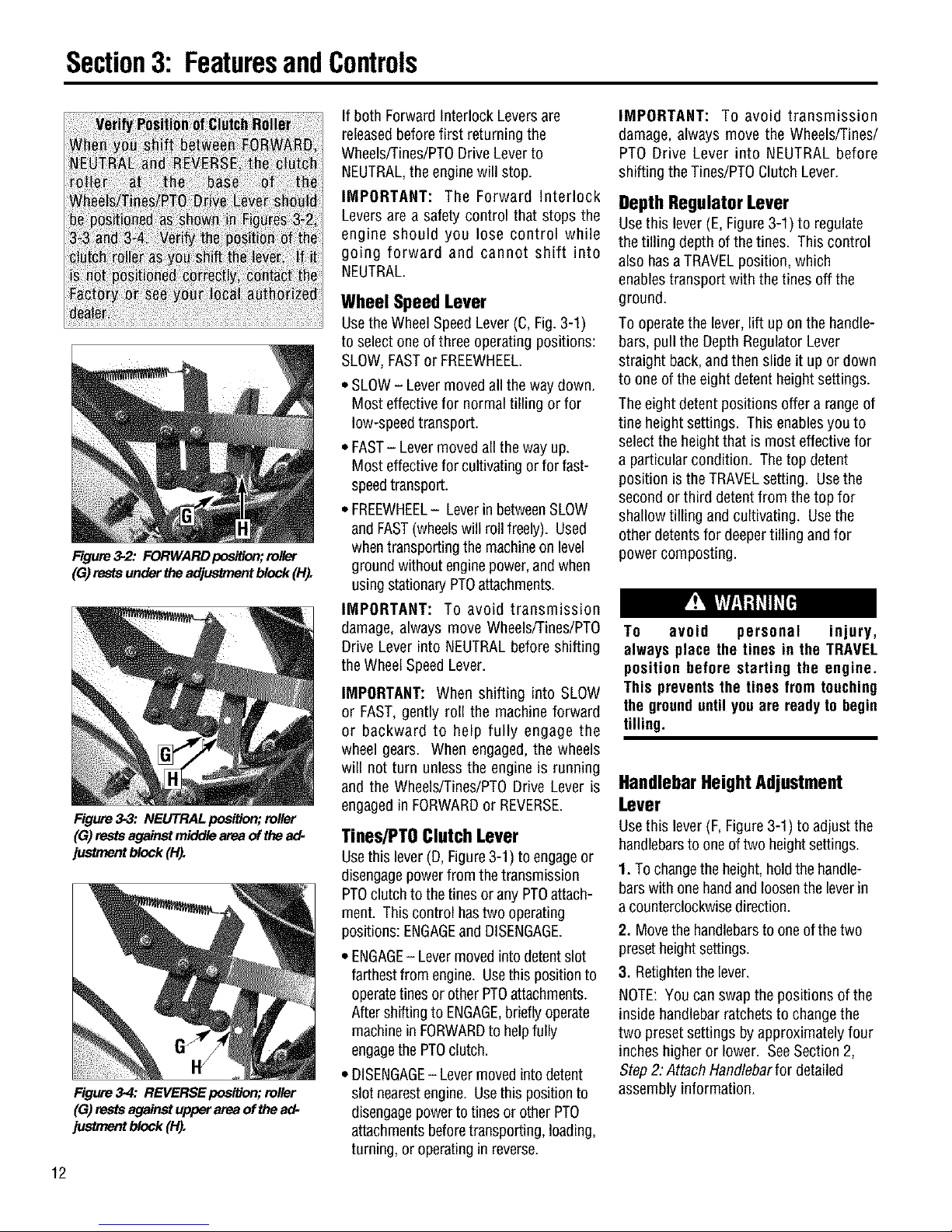
Figure 3-2: FORWARD posiUon;roller
(G)rests under lhe adj_t block (H_
Figure 3-3: NEUTRAL position; roller
(G) rests against middle area of the ad-
justment block (H).
Figure 3-4: REVERSE position; roller
(G) rests against upper area ofthe ad-
justment block (H).
12
If both Forward Interlock Leversare
releasedbefore first returning the
Wheels/Tines/PTODriveLever to
NEUTRAL,the enginewill stop.
IMPORTANT: The Forward Interlock
Levers are a safety control that stops the
engine should you lose control while
going forward and cannot shift into
NEUTRAL.
Wheel Speed Lever
Usethe Wheel SpeedLever (C,Fig.3-1)
to selectone of threeoperating positions:
SLOW,FASTor FREEWHEEL.
- SLOW- Levermovedall the waydown.
Most effectivefor normaltilling or for
low-speedtransport.
., FAST- Levermovedall theway up.
Most effectivefor cultivatingorfor fast-
speedtransport.
- FREEWHEEL- Leverin betweenSLOW
and FAST(wheelswill roll freely). Used
whentransporting the machineon level
groundwithout enginepower,andwhen
usingstationaryPTOattachments.
IMPORTANT: To avoid transmission
damage, always move Wheels/Tines/PTO
Drive Lever into NEUTRALbefore shifting
the WheelSpeedLever.
IMPORTANT: When shifting into SLOW
or FAST, gently roll the machine forward
or backward to help fully engage the
wheel gears. When engaged,the wheels
will not turn unless the engine is running
and the Wheels/Tines/PT0 Drive Lever is
engagedin FORWARDor REVERSE.
Tines/PTOClutchLever
Usethis lever(D, Figure3-1) to engageor
disengagepower fromthe transmission
PTOclutchto the tinesor any PTOattach-
ment. Thiscontrol hastwo operating
positions: ENGAGEand DISENGAGE.
- ENGAGE- Levermovedintodetentslot
farthestfrom engine. Usethis positionto
operatetinesor otherPTOattachments.
Aftershifting to ENGAGE,brieflyoperate
machinein FORWARDto helpfully
engagethe PTOclutch.
• DISENGAGE- Lever movedinto detent
slot nearestengine. Usethis positionto
disengagepowertotines or otherPTO
attachmentsbeforetransporting, loading,
turning, oroperatingin reverse.
IMPORTANT: To avoid transmission
damage, always move the Wheels/Tines/
PTO Drive Lever into NEUTRAL before
shifting the Tines/PTOClutch Lever.
DepthRegulatorLever
Usethis lever(E, Figure3-1) to regulate
the tilling depth of the tines. This control
also hasaTRAVELposition, which
enablestransport with thetines off the
ground.
To operatethe lever, lift up on the handle-
bars, pull the DepthRegulatorLever
straight back,and then slide it up or down
to one of the eightdetent heightsettings.
Theeight detent positions offer a range of
tine heightsettings. This enablesyou to
select the heightthat is most effectivefor
a particularcondition. The top detent
position is theTRAVELsetting. Usethe
second orthird detentfrom the top for
shallow tilling andcultivating. Usethe
otherdetents for deepertilling and for
powercomposting.
To avoid personal injury,
always place the tines in the TRAVEL
position before starting the engine.
This preventsthe tines from touching
the grounduntil youare ready to begin
tilling.
HandlebarHeightAdjustment
Lever
Usethis lever(F, Figure3-1) to adjust the
handlebarsto oneof two heightsettings.
1. Tochangetheheight,hold the handle-
barswith one handand loosenthe leverin
a counterclockwisedirection.
2. Movethe handlebarsto oneof the two
presetheightsettings.
3. Retightenthe lever.
NOTE:You can swapthe positions of the
inside handlebarratchetsto change the
two presetsettings by approximately four
inches higheror lower. SeeSection 2,
Step2: Attach Handlebarfor detailed
assembly information.
Page 13
The tiller handlebarscan be swungout
30°to the rightside for use onlywith the
PTOChipper/Shredderattachment. This
is doneby looseningthe mountingbolt
on the handlebarbase. Never operate
yourtiller orattachments,otherthanthe
PTO Chipper/Shredder,with the handle-
bars in the right side position. Doingso
could result in unsafe handling and
personalinjury.
EngineThrottleLever
Usethe throttle lever(G, Figure3-1) to
adjust enginespeedaswell asto start
and stopthe engine.
Move the leverawayfrom the STOP
position before starting the engine.
Enginespeedsare variableand range
betweenthe FASTand SLOW. Usethe
STOPposition to turn the engineoff.
NOTE: A secondarythrottle leveris
located onthe front of the 8HPandIOHP
engines. AseparateOn/Offsw_chmay
alsobeavailableontheengine. (See
EngineOwner'sManualfor information.)
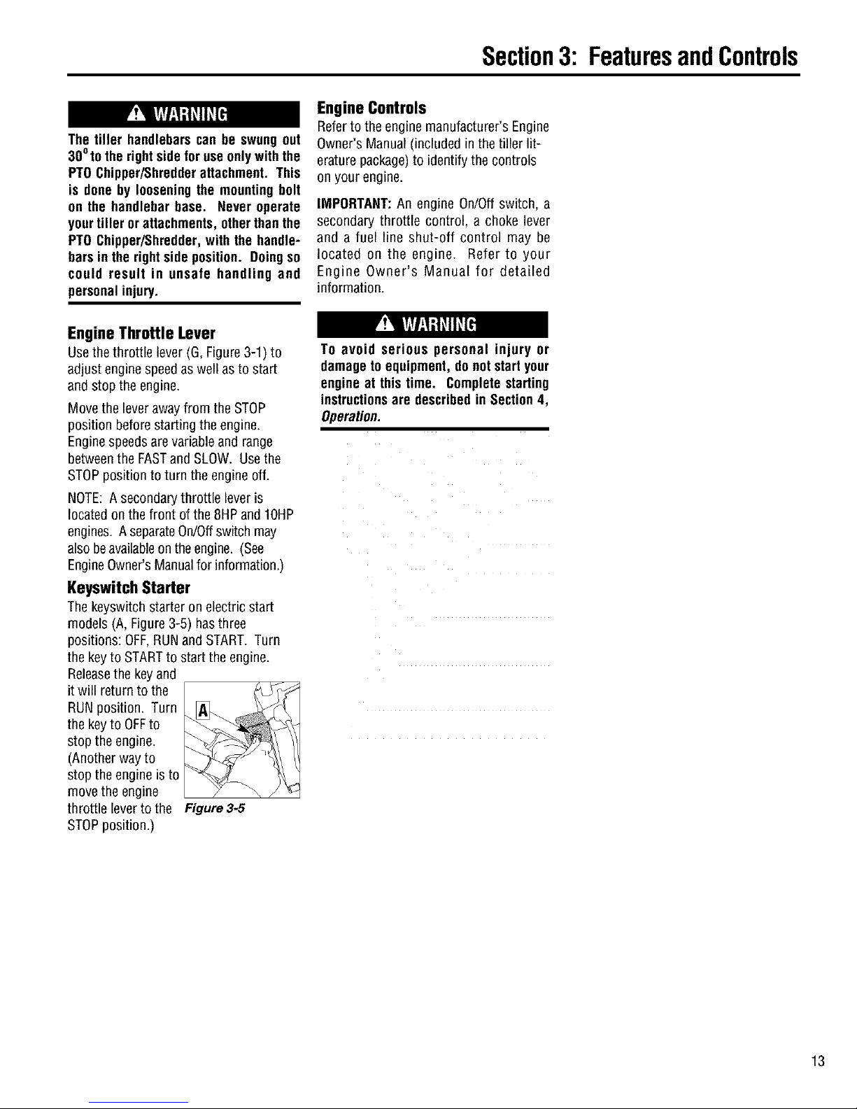
KeyswitchStarter
Thekeyswitch starter on electricstart
models (A, Figure3-5) hasthree
positions: OFF,RUNand START.Turn
the keyto STARTto start the engine.
Releasethe keyand
it will returnto the
RUNposition. Turn
the keyto OFFto
stop the engine.
(Anotherway to
stop the engine is to
move the engine
throttle leverto the Figure 3-5
STOPposition.)
Section3: FeaturesandControls
Engine Controls
Referto the engine manufacturer's Engine
Owner's Manual (included inthe tiller lit-
erature package)to identify the controls
on your engine.
IMPORTANT:An engine On/Offswitch, a
secondary throttle control, a choke lever
and a fuel line shut-off control may be
located on the engine. Refer to your
Engine Owner's Manual for detailed
information.
To avoid serious personal injury or
damageto equipment, do not startyour
engine at thistime. Complete starting
instructionsare describedin Section4,
Operation.
13
Page 14
n
Op
Before operating your machine,
carefully read andunderstandall safety
(Section 1), controls (Section 3) and
operating instructions (Section 4) in
this Manual, in the separate Engine
Owner's Manual, and on the decals on
the machine.
Failureto follow these instructionscan
resultin seriouspersonalinjury.
ration
INTRODUCTION
Readthis Section ofthe manual
thoroughly before you start the engine.
Then,take the time to familiarizeyourself
with the basic operation of the tiller
beforeusing it inyour garden. Find an
open, levelareaandpractice usingthe
tiller controls without the tines engaging
the soil (put tines inTravelsetting--
Section 3, DepthRegulator Lever). Only
after you've becomecompletelyfamiliar
with the tiller should you beginusing it in
the garden.
Your tiller and its optional PTO Power
Unit attachments are capable of
causing serious injury to untrained or
carelessoperators.
To avoid serious personal injury or
property damage, read the Owner's
Manual that is provided with any
optional accessories or attachments
before using the tiller or PTO Power
Unit.
Break-InOperation
Perform the following maintenanceduring
thefirst hours of new operation (see
MaintenanceSection in this Manualand
maintenanceinformation inthe Engine
Owner's Manual).
1. Changeengine oil afterfirst 2 hours of
newengine operation.
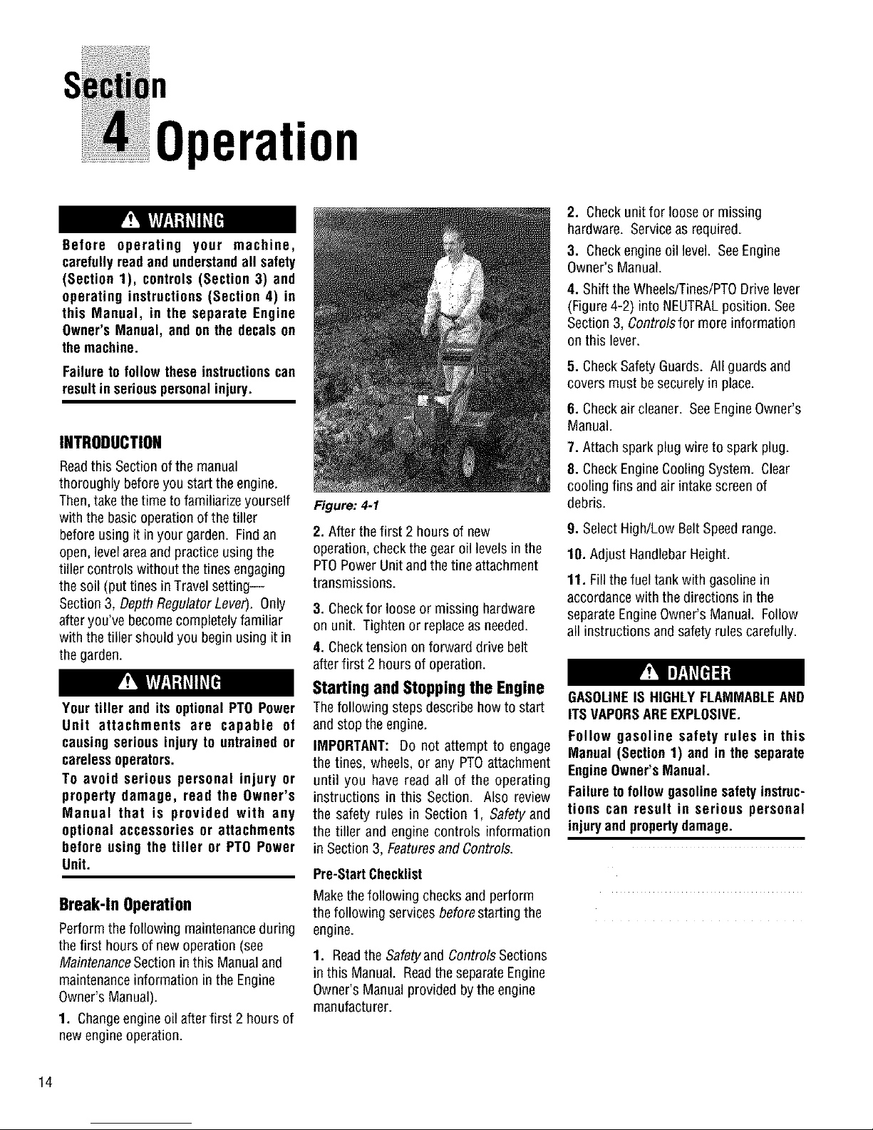
Figure: 4-1
2. After the first 2 hours of new
operation, checkthe gearoil levels inthe
PTOPower Unitandthe tine attachment
transmissions.
3. Checkfor loose or missing hardware
on unit. Tighten or replaceas needed.
4. Checktension on forward drive belt
after first 2 hours of operation.
StartingandStoppingthe Engine
Thefollowing stepsdescribehow to start
and stopthe engine.
IMPORTANT: Do not attempt to engage
the tines, wheels, or any PTOattachment
until you have read all of the operating
instructions in this Section. Also review
the safety rules in Section 1, Safety and
the tiller and engine controls information
in Section3, Featuresand Controls.
Pre-StartChecklist
Make thefollowing checks and perform
the following services before starting the
engine.
1. Readthe Safetyand ControlsSections
in this Manual. Readthe separate Engine
Owner's Manual provided by the engine
manufacturer.
2. Checkunit for looseor missing
hardware. Serviceas required.
3. Checkengine oil level. SeeEngine
Owner's Manual.
4. Shift the Wheels/Tines/PTODrivelever
(Figure4-2) into NEUTRALposition. See
Section3, Controlsfor more information
on this lever.
5. CheckSafety Guards. All guards and
covers must besecurely in place.
6. Checkair cleaner. SeeEngineOwner's
Manual.
7. Attach spark plug wire to spark plug.
8. CheckEngineCooling System. Clear
cooling fins andair intake screen of
debris.
9. Select High/Low Belt Speedrange.
10. Adjust HandlebarHeight.
11. Fillthe fueltank with gasolinein
accordancewith the directions in the
separate EngineOwner's Manual. Follow
all instructions andsafetyrules carefully.
GASOLINEIS HIGHLYFLAMMABLEAND
ITS VAPORSAREEXPLOSIVE.
Follow gasoline safety rules in this
Manual (Section 1) and in the separate
EngineOwner'sManual.
Failureto followgasolinesafety instruc-
tions can result in serious personal
injuryandpropertydamage.
14
Page 15
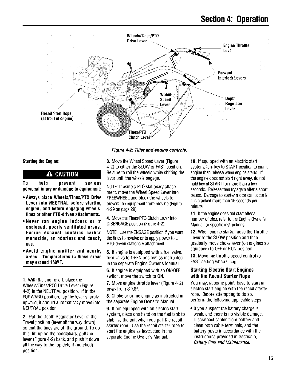
RecoilStartRope
(atfrontofengine)
Wheels/Tines/PTO
DriveLever
Tines/PTO
Figure 4-2." Tiller and engine controls.
Section4: Operation
EngineThrottle
Lever
\
_ Forward
J
Depth
InterlockLevers
Regulator
Lever
Startingthe Engine:
To help prevent serious
personalinjury or damagetoequipment:
• Always place Wheels/Tines/PTODrive
Lever into NEUTRAL before starting
engine, and before engaging wheels,
tinesor otherPTO-drivenattachments.
• Never run engine indoors or in
enclosed, poorly ventilated areas.
Engine exhaust contains carbon
monoxide, an odorless and deadly
gas.
• Avoid engine muffler and nearby
areas. Temperatures in these areas
mayexceed150OF.
1. With the engineoff, placethe
Wheels/Tines/PTODriveLever (Figure
4-2) in the NEUTRALposition. If inthe
FORWARDposition, tap the lever sharply
upward, it should automatically moveinto
NEUTRALposition.
2. Putthe DepthRegulator Leverinthe
Travel position (leverall the way down)
so that the tines are off the ground. To do
this, lift uponthe handlebars,pull the
lever (Figure4-2) back,andpush it down
all the way to the top detent (notched)
position.
3. Move theWheel SpeedLever(Figure
4-2) to eitherthe SLOWor FASTposition.
Besureto roll the wheelswhile shifting the
leveruntil thewheelsengage.
NOTE:If usingaPTOstationary attach-
ment, movetheWheelSpeedLeverinto
FREEWHEELand block thewheelsto
preventthe equipmentfrom moving(Figure
4-29 onpage29).
4. MovetheTines/PTOClutchLeverinto
DISENGAGEposition(Figure4-2).
NOTE:Usethe ENGAGEpositionifyouwant
thetinesto revolveor toapplypowertoa
PTO-drivenstationaryattachment.
5. If engineis equippedwith afuel valve,
turn valveto OPENposition as instructed
in theseparate EngineOwner's Manual.
6. If engineis equippedwith an ON/OFF
switch, move theswitch to ON.
7. Move engine throttle lever(Figure 4-2)
awayfrom STOP.
8. Chokeor prime engine asinstructed in
the separateEngineOwner's Manual.
9. If not equipped with anelectric start
system, placeone handon thefuel tank to
stabilizethe unit when you pull the recoil
starter rope. Usethe recoil starter rope to
start the engineas instructedin the
separateEngineOwner's Manual.
10. If equipped with anelectric start
system,turn keyto STARTpositionto crank
enginethen releasewhenenginestarts. If
theenginedoesnotstart rightaway,donot
holdkeyatSTARTfor morethan afew
seconds.Releasethentry againaftera short
pause.Damageto startermotorcanoccurif
itis crankedmorethan15secondsper
minute.
11. Iftheenginedoesnotstart aftera
numberoftries,refertothe EngineOwner's
Manualforspecificinstructions.
12. Whenenginestarts, move theThrottle
Leverto the SLOWposition andthen
graduallymovechoke lever(on enginesso
equipped)to OFFor RUNposition.
13. Movethe throttle speed control to
FASTsettingwhen tilling.
Starting Electric Start Engines
with the Recoil Starter Rope
You may,at some point, haveto start an
electricstart enginewith the recoil starter
rope. Beforeattempting to do so,
perform the following applicablesteps:
• If you suspectthe battery chargeis
weak,and there is novisible damage.
Disconnectcables from batteryand
cleanboth cableterminals, andthe
battery posts inaccordance with the
instructions providedin Section 5,
BatteryCareand Maintenance.
15
Page 16
Section4: Operation
Reconnectthe cables andsecurely
tighten to batteryposts. Theenginewill
rechargethe battery if the battery is still
good.
• If you suspectthe batter is "dead", or if
the batteryis damaged,disconnect, and
remove it. Haveit checkedby a
qualifiedtechnician.
• If battery has beenremoved,wrap cable
terminals atend of positive cablewith
electricaltape andsecurethecableto
the batterybracket. This will prevent
electricaldischarge.
• Before pulling the recoil starter rope,
turn the keyswitch to the RUNposition.
Move theThrottle Lever awayfrom
STOPposition and set the chokeas
applicable. SeeEngineOwner's Manual.
Stopping the Engine and Tiller
1. Tostop the wheelsand tines, movethe
Wheels/Tines/PTODriveLever into
NEUTRALposition andthen releaseboth
ForwardInterlock Levers.
16
2. Move the engineThrottle Leverto the
STOPposition. Thenonelectric start
models, turn the keyto OFF. Removethe
key for safekeeping.
NOTE: Theenginemayhavea separate
Throttle Control Leverand ON/OFFswitch
on the engine. Thesecontrols can also be
usedto stop the engine. Seethe Engine
Owner's manualfor information specific
to your engine.
Operating the Tiller
Whenfirst practicing,keeptheTines/PTO
ClutchLeverin DISENGAGEpositionand
theWheelSpeedLeverinSLOWposition.
To avoid serious personal injury or
damageto equipment:
• Alwaysplace Wheels/Tines/PTODrive
Lever in NEUTRAL before starting
engine, and before engagingwheels,
tinesor otherPTOattachments.
• Be sure thereare no obstaclesbehind
youbeforemovingin reverse.
• Wheels/Tines/PTODriveLever should
automatically return to NEUTRAL
when released from REVERSE
position. If it doesnot, movelever to
NEUTRALmanually and discontinue
use until you adjust the lever. See
Section 5, Checking and Adjusting
ReverseDrive System.
• No reverse motion should occur if
Wheels/Tines/PTODrive Lever is not
held up in REVERSE. SeeSection 5,
Checking and Adjusting Reverse
Drive System for adjustment steps.
Do not use tiller unless properly
adjusted.
• Alwaysreturn to NEUTRALand let all
motion stop before shifting to
FORWARDor REVERSE.
Thefollowing pagesprovide guidelines
for using your tiller effectivelyandsafely
in variousgardening applications. Be
sure to read Tilling Tips& Techniques,in
this Section, beforeyou actually putthe
tines into the soil.
This isa traditional standard-rotating-tine
(SRT) tiller with forward rotating tines. It
operates inacompletelydifferent manner
than counter-rotating-tine (CRT)tillers, or
from front-tine tillers.
Movingthe Tiller ForwardandTilling
1. Start the engine and gradually increase
engine speedto FAST(see Startingthe
Engine,this Section).
The ForwardInterlock Safety System is
designedfor the operator'ssafety. Do
not disconnector attempt to defeat the
purpose of the system. If the system
malfunctions,immediately contactyour
local authorized dealer or the
TROY-BILT Technical Service Depart-
ment for assistance. Do not use the
tiller or the PTO power unit until the
Forward Interlock Safety System is
functioning properly. Always test the
system before using the tiller or PTO
powerunit.
2. Testthe ForwardInterlock Safety
System. See TestingForward Interlock
System,this Section.
Keepaway fromrotatingtines. Rotating
tineswill causeinjury.
3. When practicing, setthe Depth
Regulator Leverto Travel position.
Otherwise,set the Depth Regulator Lever
to a desireddepth.
4. Move Tines/PTOClutch Leverto
ENGAGEposition if you want the tines to
turn. If practicing, leavein DISENGAGE.
IMPORTANT: Do not move Tines/PTO
Clutch Lever to ENGAGE unless
Wheels/Tines/PTO Drive Lever is in
NEUTRAL.Tiller damagemay occur!
5. To movethe tiller forward andengage
the tines,squeezeandholdeither Forward
Interlock Lever(Figure4-3)againstthe
handlebargrip, thenmove the
Wheels/Tines/PTODriveLeverdownto
FORWARDposition.
Page 17
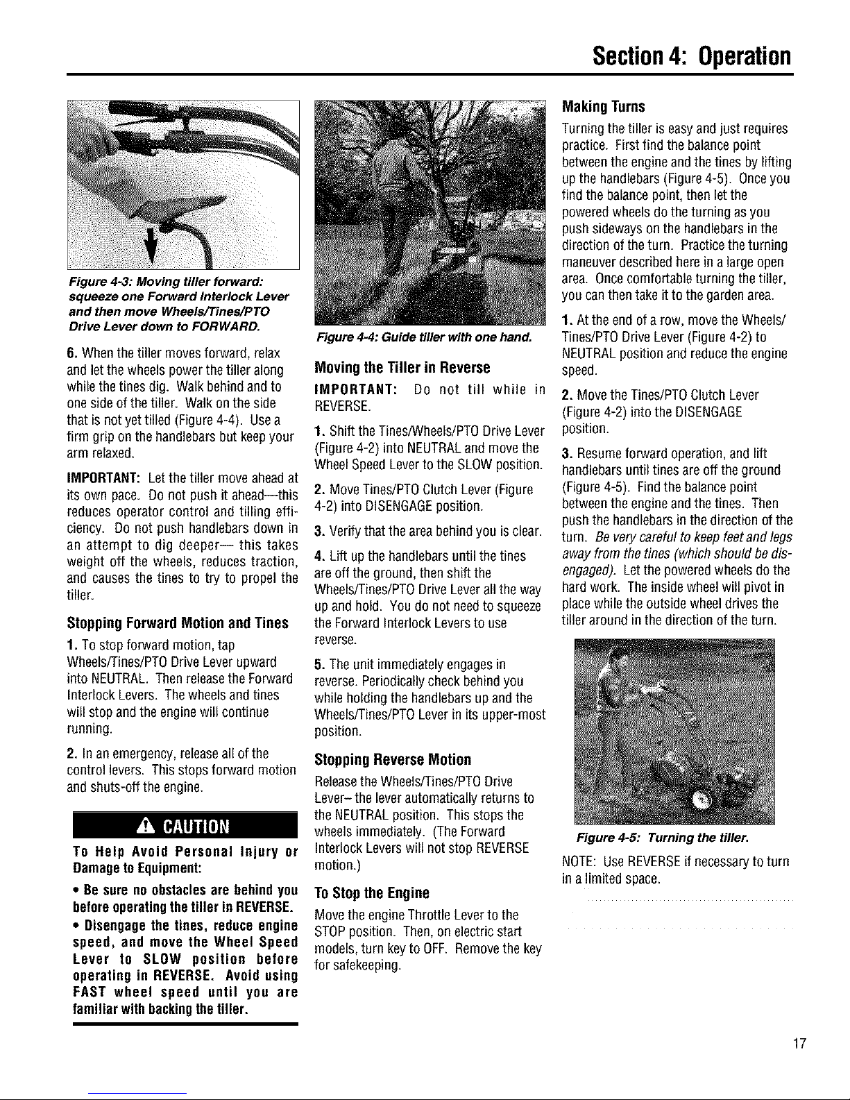
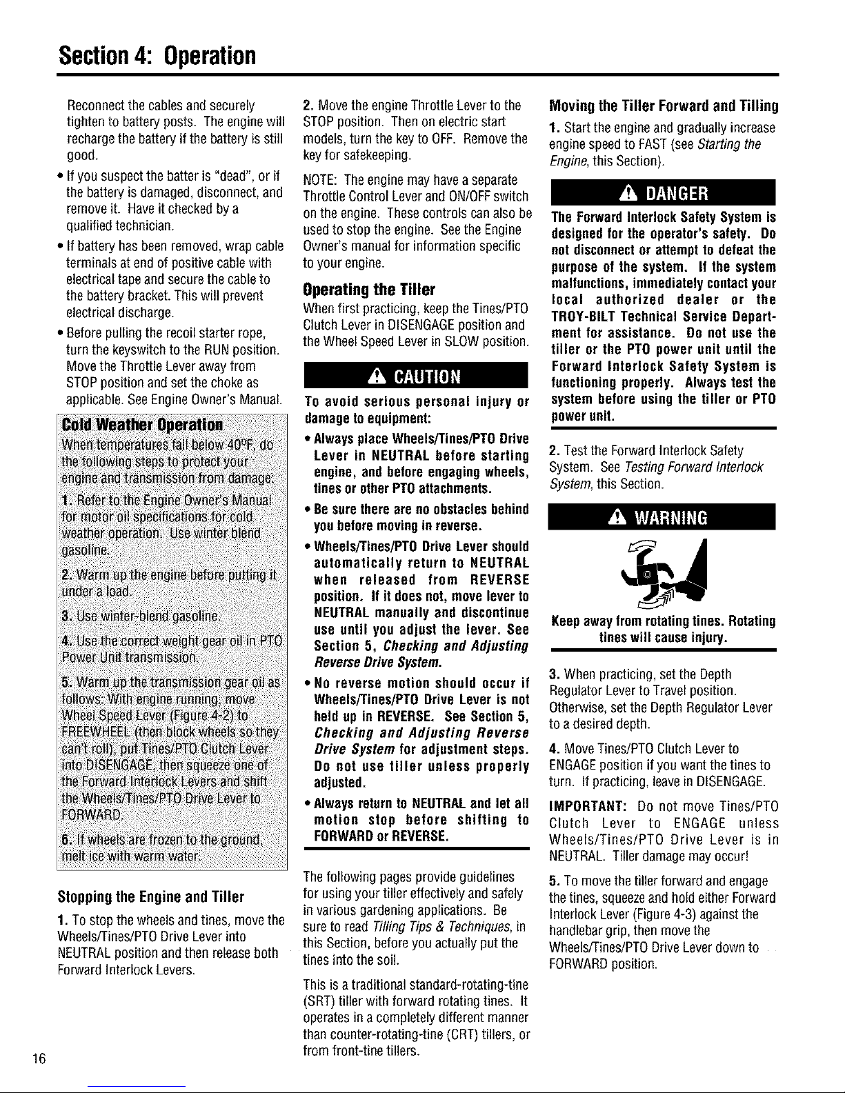
Figure 4-3: Moving tiller forward:
squeeze one Forward Interlock Lever
and then move Wheels/Tines/PTO
Drive Lever down to FORWARD.
6. Whenthe tiller movesforward, relax
and let thewheels power thetiller along
while thetines dig. Walk behindand to
one sideof the tiller. Walk on the side
that is not yet tilled (Figure4-4). Usea
firm grip on the handlebarsbut keepyour
arm relaxed.
IMPORTANT: Letthe tiller move aheadat
its own pace. Do not push it ahead--this
reduces operator control and tilling effi-
ciency. Do not push handlebars down in
an attempt to dig deeper-- this takes
weight off the wheels, reduces traction,
and causes the tines to try to propel the
tiller.
StoppingForwardMotionandTines
1. Tostop forward motion, tap
Wheels/Tines/PTODriveLever upward
into NEUTRAL.Then releasethe Forward
Interlock Levers. Thewheels and tines
will stop and the engine will continue
running.
2. In an emergency,releaseall of the
control levers. Thisstops forward motion
and shuts-off the engine.
To Help Avoid Personal Injury or
Damageto Equipment:
• Be sure no obstaclesare behindyou
beforeoperatingthe tiller in REVERSE.
• Disengagethe tines, reduce engine
speed, and move the Wheel Speed
Lever to SLOW position before
operating in REVERSE. Avoid using
FAST wheel speed until you are
familiar withbackingthe tiller.
Figure 4-4: Guide tiller with one hand.
Moving the Tiller in Reverse
IMPORTANT: Do not till while in
REVERSE.
1. Shift theTines/Wheels/PTODriveLever
(Figure4-2) into NEUTRALand movethe
WheelSpeedLever to the SLOW position.
2. Move Tines/PTOClutch Lever(Figure
4-2) into DISENGAGEposition.
3. Verify that the area behindyou is clear.
4. Lift upthe handlebarsuntil the tines
are off theground, thenshift the
Wheels/Tines/PTODriveLever allthe way
up and hold. You do not needto squeeze
the Forward Interlock Leversto use
mve_e.
5. Theunit immediatelyengagesin
reverse. Periodicallycheck behindyou
while holding the handlebarsupandthe
Wheels/Tines/PTOLeverin its upper-most
position.
Stopping Reverse Motion
Releasethe Wheels/Tines/PTODrive
Lever- the lever automatically returns to
the NEUTRALposition. This stops the
wheels immediately.(TheForward
Interlock Leverswill notstop REVERSE
motion.)
ToStopthe Engine
Move the engineThrottle Leverto the
STOPposition. Then, on electric start
models, turn keyto OFF. Removethe key
for safekeeping.
Section4: Operation
MakingTurns
Turningthe tiller is easyand just requires
practice. First find the balance point
betweenthe engine and thetines by lifting
upthe handlebars(Figure4-5). Onceyou
find the balancepoint, then letthe
poweredwheelsdo theturning as you
pushsidewayson the handlebarsin the
direction of theturn. Practice theturning
maneuverdescribed herein alarge open
area. Oncecomfortableturning the tiller,
you canthen take it to the gardenarea.
1. Atthe endof a row, movethe Wheels/
Tines/PTODrive Lever(Figure4-2)to
NEUTRALpositionand reducethe engine
speed.
2. Move the Tines/PTOClutch Lever
(Figure4-2) into the DISENGAGE
position.
3. Resumeforward operation, and lift
handlebarsuntil tines are off theground
(Figure4-5). Findthe balancepoint
betweenthe engine and thetines. Then
pushthe handlebarsin the direction of the
turn. Be very careful to keepfeetandlegs
away fromthe tines (which should bedis-
engaged). Letthe poweredwheels do the
hardwork. The insidewheelwill pivotin
placewhile the outsidewheel drives the
tiller around inthe direction ofthe turn.
Figure 4-5: Turning the tiller.
NOTE:Use REVERSEif necessaryto turn
in alimited space.
17
Page 18
Section4: Operation
4. Whenthe turn is complete,shift to
NEUTRALand lowerthe handlebars.
Move Tines/PTOClutch Leverbackto
ENGAGEposition and resumeforward
operation.
Transporting The Tiller Around
Your Property
When the engineis running, thetiller's
poweredwheels make moving the tiller to
and from the gardeneasy. If the engine is
not running set the WheelSpeedLever to
FREEWHEELposition to roll the tiller to
another location.
To help avoid personal injury from
revolving tines, always put the
Tines/PTOClutch Lever in DISENGAGE
positionbeforetransporting,loading,or
unloadingUiler.
1. Placethe Tines/PTOClutch Leverin
DISENGAGEposition.
2. MoveDepthRegulatorLeverdownall the
way intotheTravelsetting.
3. If using enginepower, moveWheel
SpeedLeverto either SLOWor FAST,and
usethe Wheels/Tines/PTODrive Leverto
drivethe wheels.
4. If theengine is stopped, moveWheel
SpeedLeverto FREEWHEEL,and
manually push tiller.
Testing the Forward
Interlock SafetySystem
The Forward Interlock SafetySystem is
designedto shut thetiller engine off
immediately if you losecontrol and
cannot stop moving FORWARDby
shifting theWheels/Tines/PTODrive Lever
into NEUTRAL. Whenyou releaseboth
Forward Interlock Levers,they send
ground to the ignition system thereby
stopping theengine. Squeezingoneor
both levers up against the handlebars
enablesthe ignition system;therefore,
you must squeezeat leastone lever
whenever the Wheels/Tines/PTODrive
Leveris engagedin FORWARD.
IMPORTANT: The interlock system also
prevents the engine from starting if the
Wheels/Tines/PTODrive Lever is engaged
in FORWARD.
18
The ForwardInterlockSafetySystem is
designedfor the operator's safety. Do
not disconnector attempt to defeat the
purpose of the system, if the system
malfunctions, immediately contactyour
local authorized dealer or the
TROY-BILT Technical Service Depart-
ment for assistance. Do not use the
tiller or the PTO power unit until the
Forward Interlock Safety System is
functioning properly. Always test the
system before using the tiller or PTO
powerunit.
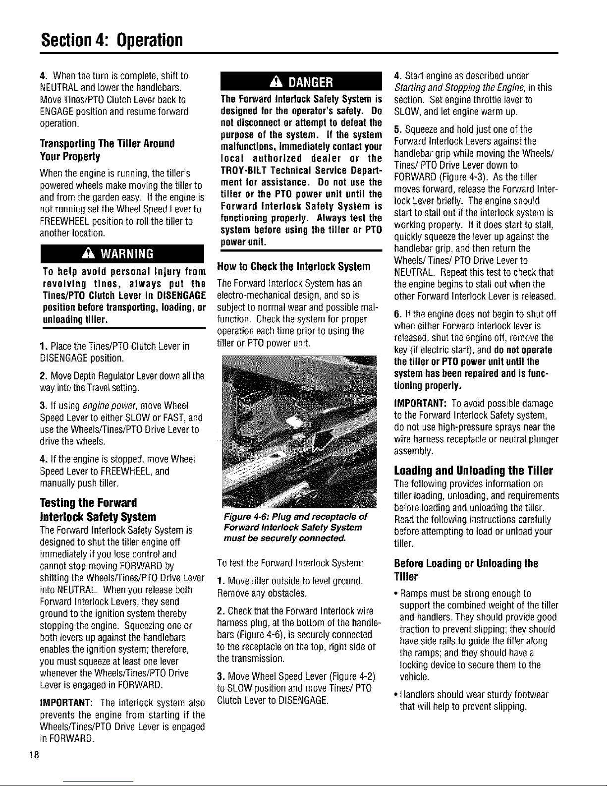
HowtoCheckthe Interlock System
The Forward Interlock System hasan
electro-mechanicaldesign, and so is
subject to normal wearand possiblemal-
function. Checkthe system for proper
operationeach time prior to using the
tiller or PTOpower unit.
Figure 4-6: Plug and receptacle of
Forward Interlock Safety System
must be securely connected.
To test the ForwardInterlockSystem:
1. Movetiller outside to levelground.
Removeany obstacles.
2. Checkthat the ForwardInterlockwire
harnessplug, at the bottom ofthe handle-
bars (Figure4-6), is securelyconnected
to the receptacleon the top, right sideof
the transmission.
3. MoveWheel SpeedLever(Figure4-2)
to SLOWposition and moveTines/PTO
ClutchLever to DISENGAGE.
4. Start engine asdescribed under
Starting andStopping the Engine,in this
section. Setengine throttle lever to
SLOW,and let enginewarm up.
5. Squeezeand hold just one of the
Forward Interlock Leversagainst the
handlebargrip while movingthe Wheels/
Tines/PTO DriveLever down to
FORWARD(Figure4-3). As the tiller
movesforward, releasethe ForwardInter-
lock Leverbriefly. The engineshould
start to stall out if the interlock system is
working properly. If it does start tostall,
quickly squeezethe lever up againstthe
handlebargrip, andthen return the
Wheels/Tines/PTO Drive Leverto
NEUTRAL. Repeatthis test to checkthat
the engine beginsto stall out when the
other ForwardInterlock Leveris released.
6. If the enginedoes not beginto shut off
when either ForwardInterlock leveris
released,shut theengine off, removethe
key (if electric start), and donotoperate
the tiller or PTOpowerunituntil the
systemhasbeenrepaired and isfunc-
tioningproperly.
IMPORTANT:To avoid possible damage
to the ForwardInterlock Safetysystem,
do not use high-pressure sprays nearthe
wire harnessreceptacleor neutralplunger
assembly.
Loading and Unloading the Tiller
Thefollowing provides information on
tiller loading, unloading, andrequirements
before loading and unloading the tiller.
Readthe following instructions carefully
beforeattempting to load or unloadyour
tiller.
BeforeLoadingorUnloadingthe
Tiller
• Ramps must be strong enoughto
support the combined weight of thetiller
and handlers.Theyshould providegood
traction to prevent slipping; they should
haveside railsto guide thetiller along
the ramps;and they should havea
locking deviceto securethemto the
vehicle.
• Handlersshould wear sturdy footwear
that will helpto preventslipping.
Page 19
Section4: Operation
• Turnthe vehicle's engineoff and apply
its parkingbrake.
• Positionthe loading vehicleso that the
ramp angle isas flat aspossible (the
less incline to the ramp,the better).
Loadingthe Tiller
1. Use loading rampsthat arestrong and
wide enough to safely holdthe weight of
the tiller andthe operator combined--
your tiller weighs between280 and 325
Ibs.
2. Move the Tines/PTOClutch Lever
(Figure4-2) into DISENGAGEposition.
3. Setthe DepthRegulatorlever (Figure
4-2) to the Travel position.
4. Move WheelSpeedLever (Figure4-2)
into SLOWposition and reducethe
enginethrottle speed.
5. Shift the Wheels/Tines/PTOLever
(Figure4-2) into FORWARDposition and
follow the tiller up the ramps (Figure4-7).
Checkthe wheelsas you move the tiller
forward. Ensurethat they moveupthe
center of eachramp.
6. Preventtiller from rolling in vehicle.
LeaveWheel SpeedLeverin FASTor
SLOWposition, chock wheels with blocks
and tie down the tiller.
Figure 4-7: To go up ramps, use
FORWARD drive.
Unloading the Tiller
IMPORTANT:Neverunload thetiller in
FORWARDdrive. Thetiller could tip
forward andexposeyou to the tines
(which should bedisengagedas
instructed).
1. Use loading rampsthat arestrong and
wide enough to safely holdthe weight of
the tiller andthe operator combined--
your tiller weighs between280 and 325
Ibs.
2. Move the Tines/PTOClutch Lever
(Figure 4-2) to DISENGAGEposition.
3. Setthe DepthRegulatorLever (Figure
4-2) to the Travel position.
4. Move WheelSpeedLever (Figure4-2)
to SLOWposition and reducethe engine
throttle speed.
IMPORTANT: Look behind you before
you backdown the ramp to ensurethat all
is clear. While descending, keepchecking
for obstacles behindyou.
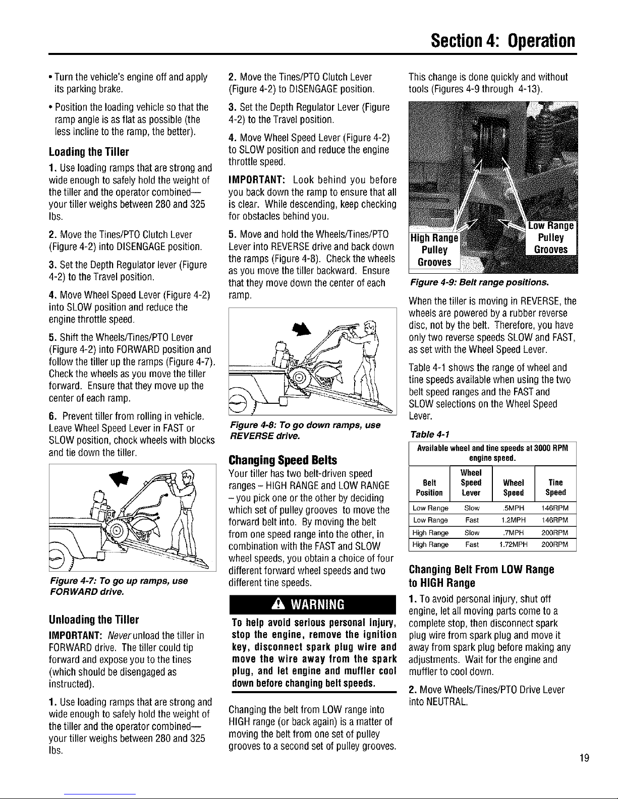
5. Move and holdthe Wheels/Tines/PT0
Lever into REVERSEdrive and backdown
the ramps (Figure4-8). Checkthewheels
asyou move the tiller backward. Ensure
that they movedown the center of each
ramp.
Figure 4-8: TOgo down ramps, use
REVERSE drive.
Changing Speed Belts
Your tiller hastwo belt-driven speed
ranges- HIGH RANGEand LOWRANGE
- you pick one or the other by deciding
which setof pulleygrooves to movethe
forward belt into. Bymoving the belt
from onespeed rangeinto the other, in
combination with the FASTand SLOW
wheel speeds,you obtain a choice of four
different forward wheel speedsandtwo
different tine speeds.
To help avoid serious personal injury,
stop the engine, remove the ignition
key, disconnect spark plug wire and
move the wire away from the spark
plug, and let engine and muffler cool
downbeforechangingbelt speeds.
Changingthe beltfrom LOWrange into
HIGHrange (or backagain) isa matter of
moving the belt from one setof pulley
grooves to a second set of pulleygrooves.
This changeis done quickly andwithout
tools (Figures4-9 through 4-13).
Pulley
Figure 4-9: Belt range positions.
Whenthe tiller is moving inREVERSE,the
wheels arepowered bya rubber reverse
disc, not bythe belt. Therefore,you have
onlytwo reversespeedsSLOWand FAST,
as set with the WheelSpeedLever.
Table4-1 showsthe rangeof wheeland
tine speedsavailablewhen using the two
beltspeed rangesand the FASTand
SLOWselectionson theWheel Speed
Lever.
Table 4-1
AvailablewheelandUnespeedsat 3000RPM
enginespeed.
Belt WheelSpeedWheel Tine
Lever _ Speed _ Speed
Low Range Slow .5MPH _46RPM
Low Range Fast 1.2MPH 146RPM
High Range Slow .7MPH 200RPM
High Range Fast 1.72MPH 200RPM
ChangingBeltFromLOWRange
to HIGHRange
1. To avoid personalinjury, shut off
engine,let all moving parts come to a
completestop, then disconnect spark
plug wire from spark plug andmove it
away from spark plug beforemaking any
adjustments. Wait for the engineand
muffler to cool down.
2. MoveWheels/Tines/PTODriveLever
into NEUTRAL.
19
Page 20
Section4: Operation
The HIGH speed belt range position
combined with a FAST wheel speed
setting propelsthe tiller at the fastest
pace. Reducethe enginethrottle speed
whenstartingoutto help avoidpersonal
injury or propertydamage if using this
speedcombination.
3. Kneelon left side of tiller. Tocreate
belt slack, reachoverto right side of the
pulleys and push inatthe center of the
belt with a finger. At the sametime, use
your left hand to work the belt part-way
onto the lower-front transmission pulley
groove (Figure4-10).
4. Goto right side of tiller and finish
seatingthe belt.
5. Still holding the lever up in REVERSE
position, and working from the left side of
thetiller, movethe beltfrom the lower-
front transmission grooveto the lower-
rear transmission groove.
6. Goto the right side of the tiller and
finish seatingthe belt (Figure4-13).
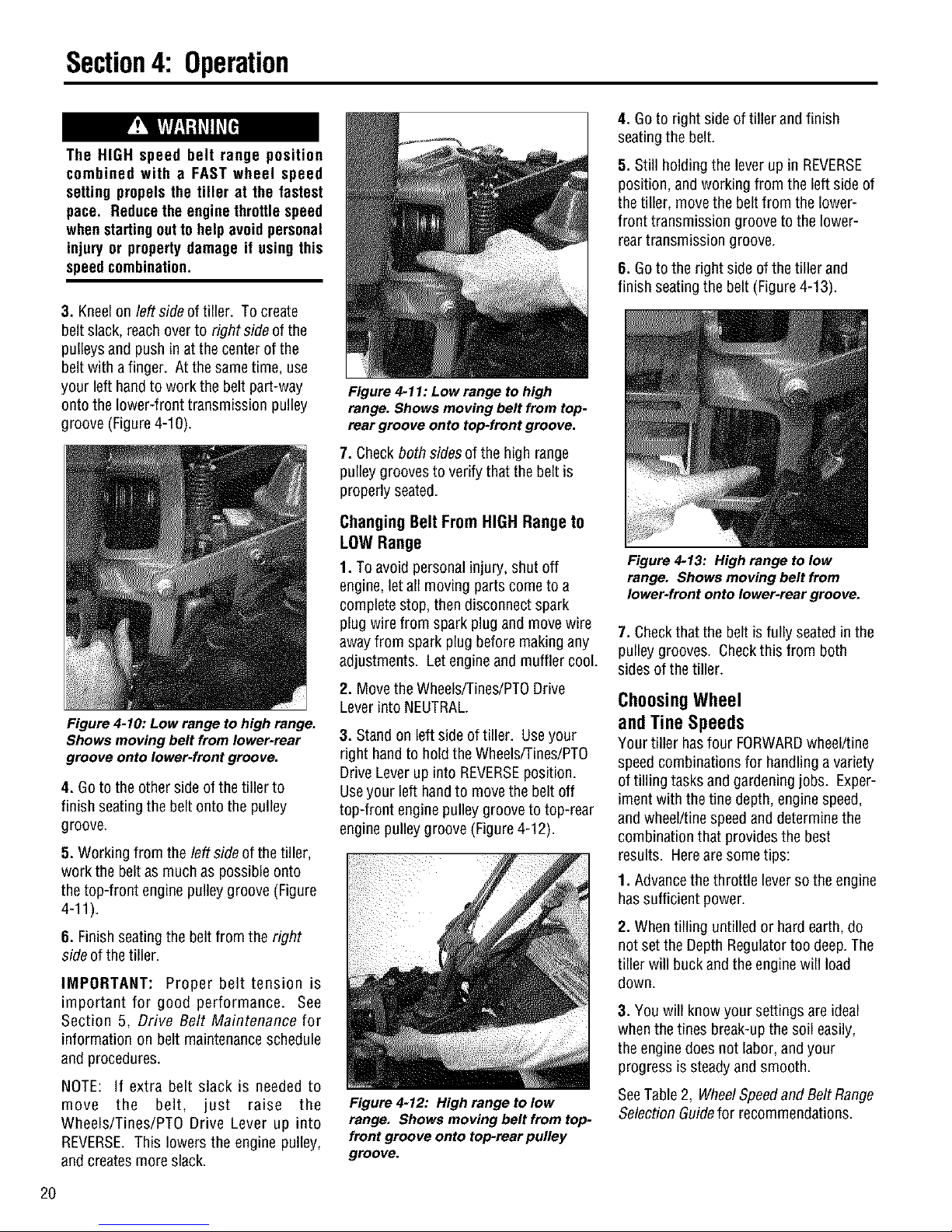
Figure 4-11: Low range to high
range. Shows moving belt from top-
rear groove onto top-front groove.
7. Checkboth sidesof the high range
pulley groovesto verify that the belt is
properly seated.
Figure 4-10: Low range to high range.
Shows moving belt from lower-rear
groove onto lower-front groove.
4. Goto the other side of the tiller to
finish seatingthe belt onto the pulley
groove.
5. Working from the left side of the tiller,
work the beltas muchas possibleonto
the top-front engine pulley groove (Figure
4-11).
6. Finish seatingthe beltfrom the right
side of thetiller.
IMPORTANT: Proper belt tension is
important for good performance. See
Section 5, Drive Belt Maintenance for
information on belt maintenanceschedule
and procedures.
NOTE: If extra belt slack is needed to
move the belt, just raise the
Wheels/Tines/PTO Drive Lever up into
REVERSE.This lowers the engine pulley,
and createsmore slack.
Changing Belt From HIGH Range to
LOW Range
1. To avoid personalinjury, shut off
engine,let all moving parts come to a
complete stop, thendisconnect spark
plug wire from spark plug and move wire
awayfrom spark plug before makingany
adjustments. Let engineand muffler cool.
2. Move theWheels/Tines/PTODrive
Lever into NEUTRAL.
3. Standon left side of tiller. Useyour
right hand to hold the Wheels/Tines/PTO
Drive Lever up into REVERSEposition.
Useyour left handto movethe belt off
top-front engine pulley grooveto top-rear
engine pulleygroove (Figure4-12).
Figure 4-12: High range to low
range. Shows moving belt from top-
front groove onto top-rear pulley
groove.
Figure 4-13: High range to low
range. Shows moving belt from
Iower-frent onto lower-rear groove.
7. Checkthat the belt isfully seatedinthe
pulley grooves. Checkthis from both
sides of thetiller.
ChoosingWheel
and Tine Speeds
Your tiller hasfour FORWARDwheel/tine
speedcombinations for handling a variety
of tilling tasks and gardening jobs. Exper-
iment with the tine depth, enginespeed,
and wheel/tinespeedanddeterminethe
combination that provides the best
results. Herearesome tips:
1. Advancethe throttle leverso the engine
hassufficient power.
2. When tilling untilled or hard earth, do
not set the Depth Regulatortoo deep.The
tiller will buckand the enginewill load
down.
3. You will know your settings are ideal
whenthe tines break-up the soil easily,
the enginedoes not labor, and your
progress issteadyand smooth.
SeeTable2, WheelSpeedand BeltRange
Selection Guidefor recommendations.
2O
Page 21

Section4: Operation
SLOWGEAR,LOWBELTRANGE
For:
• Tillinginsod.
• Tillingin hardclay,
• Tilling understandingcorn-
stalks intoughsoil conditions.
• Tilling undercovercrops.
• Preparingadeepseedbed,
• Tilling instonysoil.
• Tilling underresiduesand
organicmatter,
• Mixingin fertilizers,manure.
SLOWGEAR,NIGHBELTRANGE
For:
• Tillingin sodor hardclay.
• Tillingunderstandingcorn-
stalks(slow,steadyspeed
allowstime to shredstalks).
• Tillingundercovercrops
(bestwheelspeedand belt
speedrangein mostsoils).
• Preparingseedbeds(best
speedchoicein most soils).
• Tillingin stonyground.
• Buildingraisedgardenbeds.
• Mixingin fertilizer.
• Usinghiller wingsin hard
soil.
• Mixingfertilizer andmanure.
• Tillingresiduesandorganics.
TillingTips& Techniques
Letthetiller dothework
• While tilling, relax and letthe wheels
pull the tiller along while the tinesdo
the digging. Walk on theside that is not
yet finished (to avoid making footprints
inthe freshly tilled soil) and lightly, but
securelygrip the handlebarwith just
one hand(Figure4-4).
• Avoid pushingdown on the handlebars
inan attempt to forcethe tiller to dig
deeper. Doing so takesthe weight off
the poweredwheels, causingthem to
losetraction. Without thewheels
helping to hold the tiller back,the tines
will attempt to propel thetiller - often
causingthe tiller to skip rapidly across
the ground. (Sometimes, slight
downward pressureonthe handlebars
will helpget through aparticularly
tough section of sod or unbroken
ground, but inmost casesthis won't be
necessary.)
Tilling depths
• Avoid trying to dig too deeplytoo
quickly, especiallywhenbusting sod or
tilling soil that hasn't beentilled for
some time. Useshallow depth settings
(only an inchor two deep)for the first
passesthrough the gardenarea.
FASTGEAR,LOWBELTRANGE
For:
Goingoverseedbedfor the
lasttime beforeplantingcrops.
Coveringoverseedsinwide
row or plot planting(lift han-
dlebarsto avoidgoingtoo
deep).
Hillingandfurrowing.
Makingraisedbeds.
Cultivating(lift handlebarsto
avoidgoingtoo deep).
•Tilling largeareas.
•Tillingorganicmatterin.
Cultivatingbetweenraised
bedswith optional
hiller/furrowerattachment.
With eachsucceeding pass,adjust the
depth regulatorto diganother inchor
two deeper. (Wateringthe gardenarea
afew daysprior to tilling will make
tilling easier,aswill letting the newly
worked soil set for a day or two before
making afinal, deeptilling pass.)
• Whencultivating (breakingup the
surfacesoil aroundplantsto help
destroyweeds), usevery shallowdepth
settingsto preventinjuryto plantswhose
rootsoften growcloseto thesurface. If
needed,lift uponthe handlebarsslightly
to preventthetinesfrom diggingtoo
deeply. Cultivatingon aregularbasisnot
onlyeliminatesweeds,it alsoloosensand
aeratesthe soilfor bettermoisture
absorptionandfasterplantgrowth.
Avoidtillingwet, soggysoil
Tilling wet soil often results in large,hard
clumps of soil thatcan interferewith
planting. Iftime permits, waitaday or
two after heavy rainsto allow the soil to
dry beforetilling. Testthe soil by
squeezingit into a ball. If it compresses
too easily,it istoo wet to till.
FASTGEAR,HIGHBELTRANGE
For:
Preparingseedbedsfor
planting.
Coveringseedswith lessneed
to holdup thehandlebars.
• Cultivating(tillertravelsfaster,
rideshigheron thesoil;allows
engineRPMto bereduced;
handlebarsdon't haveto be
raised).
• Keepinglargeareastilledand
cultivatedin thesummer.
•Tilling organicmatter under.
• Movingtiller quickly.
• Cultivatingbetweenraised
bedsusing theoptional
hiller/furrower.
To helpavoid personalinjury, beaware
that the tiller can unexpectedlybounce
up orjumpaheadand propelawayfrom
you if the tines strike hard or frozen
ground, or buried obstacles like large
stones, roots or stumps. Always use
the following precautions to help
maintaincontrolofthetiller:
• Walk behind and to the side of the
tiller. Useonehand onthe handlebars,
relaxing your arm but with a secure
handgrip.
• Use shallow depthregulatorsettings.
Till graduallydeeper.
• Use slower wheel, tine and engine
speeds.
• Clear the tilling area of all large
stones,rootsandotherdebris.
• Do not putdownwardpressureon the
handlebars. If needed, apply slight
upwardhandlebarpressureto keep the
tinesfromdiggingtoodeeply.
• Avoid contacting hard soil or sod at
the endof a row - reduceenginespeed
and lift handlebarsto raise tinesoutof
thesoil.
• In An Emergency, stop tines and
wheels by movingWheels/Tines/PTO
DriveLeverto NEUTRAL. If youcannot
reachthe lever or havelostcontrol, Let
GoOfThe HandlebarsandAll Controls.
21
Page 22

Section4: Operation
TillingTips& Techniques
Avoidmakingfootprints
When possible,walkonthe untilledside
of theunit to avoid making footprints in
the freshlytilled soil (Figure 4-4). Foot-
prints causesoil compactionthat can
hamperroot penetrationandcontribute
to soil erosion. Theycanalso "plant"
unwantedweedseedsbackinto the
newlytilled soil.
Suggestedtilling patterns
• When preparingaseedbed,go over
the same path twice inthe first row,
then overlap one-halfthe tiller width
on the rest of the passes(Figure4-
14). Whenfinished in onedirection,
makea secondpassata right angle as
shown in Figure4-15. Overlapeach
passfor best results (in very hard
ground it may takethreeor four
passesto thoroughly pulverizethe
soil).
• If the gardensizewill not permit
lengthwiseand then crosswise tilling,
then overlapthe first passesby one-
halfa tiller width, followed by succes-
sive passesat one-quarterwidth
(Figure4-16).
• With planning,you canallow enough
room between rows to cultivate
(Figure4-17). Leaveroom for the
hood width, plus enough extra room
for future plant growth.
Tilling onslopes
If you must garden on sloping ground,
pleasefollow two very important guide-
lines:
1. Till only on moderateslopes, never
on steepinclineswherefooting is
difficult (review safety rules in the
"Safety" Sectionofthis Manual).
2. Werecommendtilling up and down
slopes rather thanterracing. Tilling
vertically on aslope allows maximum
planting areaand also leavesroom
for cultivating.
IMPORTANT: When tilling on slopes,
be sure the correct oil level is main-
tained in the engine (check every one-
half hour of operation). The incline of
the slope will causethe oil to slant away
from its normal levelandthis can starve
engine parts of required lubrication.
Keepthe engine oil levelat the full point
at all times!
A. Tilling upanddownslopes:
• To keepsoil erosion to aminimum, be
sureto add enough organic matter to
the soil so that it hasgood moisture-
holding texture andtry to avoid leaving
footprints or wheel marks.
To avoid serious personal injury or
damagetothe equipment:
• Do not operatetiller on a slope too
steep for safe operation. Go slowly
on any slope. Make sure you have
goodfooting.
• Wear footwear that increases
stabilityand reducesslippage.
• Do not use FAST wheel speed
positionwhenon slopedground.
• Do not shift the Wheel Speed Lever
when headingup or downa slope. If
lever is accidentally moved to FREE
WHEELposition, the tiller could roll
outofcontrol.
• To prevent enginedamagedueto oil
starvation (on slopes,the engine is
inclined and oil moves away from
surfaces that need lubrication), be
sure the correct oil level is main-
tained during all uphill/downhill
tilling operations. Checkthe level of
the oil in yourengineafter every one-
half hourofoperation.
• When tilling vertically, try to makethe
first pass uphill asthe tiller digs more
deeplygoing uphill than it does
downhill. Insoft soil orweeds,you
may haveto lift the handlebarsslightly
while going uphill. When going
downhill, overlap the first pass by
about one-halfthe width of thetiller.
HINT: For best results, usethe HIGH
belt rangeand SLOWwheelspeedlever
position. SeeChanging SpeedBelts in
this section for more information on
changingto high range.
Figure4-14
Figure4-15
Figure4-16
]
22
Page 23

TillingTips& Techniques
Figure 4-18
B.Terrace Gardening:
• Whena slope is too steeportoo short
for vertical tilling, it may be necessary
to till across the slopeand create
terraced rows. Terracesare rows that
are cut into the sideof a slope,creating
a narrow, but flatareaonwhich to
plant.
• Ona long slope, you can makeseveral
terraces, onebelowthe other.
• Terracesshould be only 2-to-3 feet
wide. Diggingtoo far into the side of
the slopewill exposepoorsubsoil that
is unproductivefor plants.
• To createaterrace,start at thetop of
the slopeandwork down. Go backand
forth across thefirst row as shown in
Figure4-18.
• Eachsucceeding lowerterrace is
started bywalking belowtheterrace
you're preparing. Foradded stability of
thetiller, always keepthe uphill wheel
in thesoft, newlytilled soil. Do not till
the last 12" or more of the downhill
outside edgeof eachterrace. This
untilled strip helps prevents the
terracesfrom breakingapartand
washing downhill. It also provides a
walking path betweenrows.
C. Tillingacrossslopes
withoutterracing
• If vertical orterracing gardening aren't
practicalfor you, then you cantill
laterallyacrossa slope. Wedon't
reallyrecommend this method asit
cancreate unsure footing and invites
soil erosion.
• Studythe terrain to makecertain the
slope is not too steepfor safetilling.
If possible, maketerraced rowsor till
vertically.
• Movethe belt into LOWbelt rangeand
the WheelSpeedGearLeverto SLOW
position. As in terracegardening, start
atthe top of the slopeand overlapthe
first pass by halfthe width of thetiller.
Foraddedstability, keepthe uphill
wheelin the soft, newlytilled soil. Each
succeedingterraced areais started by
walking belowthe terrace you are
preparing (Figure4-19).
Section4: Operation
Clearingthe tines
Thetines havea self-clearing action
which helps to eliminate most tangling
of debris. However,occasionally dry
grass,stringy stalks or tough vines may
becometangled.
Followthese proceduresto helpavoid
tangling and to clearthe tines, if
necessary.
Beforeclearing the tines byhand, stop
the engine, allow all moving parts to
stop and disconnect the spark plug
wire. Failure to follow this warning
couldresultin personal injury.
• To reducetangling, setthe Depth
Regulatordeepenough to get
maximum "chopping" action as the
tines chopthe materialagainst the
ground. Also, try to till under crop
residuesor covercrops while theyare
green, moist andtender.
• While power composting, try swaying
the handlebarsfrom side to side (about
6"to 12"). This"fishtailing" action
often clearsthe tines of debris.
• It may be necessaryto removethe
debris by hand(a pocketknife will help
you to cut awaythe material).
Figure 4-19: Make a terrace in just 4
or 5 passes with the tiller.
23
Page 24

Section4: Operation
TillingTips& Techniques
POWERCOMPOSTING
Powercomposting meanstilling under
and burying inthe soil all mannerof
organic matter suchas crop residues,
leaves,grass clippings and covercrops.
This materialwill decomposeduring the
non-growing seasonand add important
natural nutrients to the soil.
After tilling under crop residues,add
more organic matter suchas leaves,
grass clippings andeven kitchenscraps.
When tilled into the soil, this organic
matterwill decomposeandadd even
more important nutrients to the soil.
After power composting, you maywant
to plant a "green manure" cover crop to
protect the soil during the off-season.
1. As you moveforward intoa row of
stalks,aim the tiller sothat the stalks go
betweenthe left wheelandthe transmis-
sion case(Figure4-19). Do not usethe
right wheel becausedamagecould occur
to theair cleaner, carburetor or throttle
linkage.
Whenpower composting, do not keep
the DepthRegulator Lever at a deep
settingif thetiller jumpsorbucks.
If jumping or bucking occurs, move
the Depth Regulator Lever down to
one of the shallower settings and
then slowly increasethe tilling depth
on later passes.
Failure to complycouldresult in loss
of tiller control, propertydamage or
personalinjury.
Begin by composting crop residues such
as leftover vines, stalks,stems and
roots. Power compost thesecrop
residuesas soon asthey finish bearing.
The soonerthis is done,the better,as
tender green matter is easierto till
under. Usethe deepestdepth regulator
setting possible without causing the
engineto labor or the tiller to jump
ahead.
Standingcornstalks of reasonableheight
canbe powercomposted (Figure4-20).
Pushing over (but not uprooting) corn-
stalks will often makeit easierfor your
tiller to chop up the stalks. Keepthe
tines clear of excessivetangling by"fish-
tailing" or frequently using reverse.
Makeseveral passes,then return a few
days laterto finish off any remaining
stubble.
Growa crop of clover,alfalfa,
buckwheat,peas, beans,ryegrass,
grain, or kaleand then till it into the soil
prior to the plantingseason.
Wide-Row Planting
Thewide-row planting techniqueis
spreadingseedsanywherefrom 10
inchesto 2 feet wide or more. As a
result, you cangrow anywherefrom 3 to
4 times (or more) produce in the same
spacethat is normally setaside for an
areathat has narrow, single rows.
Wide-row planting automaticallyshades
the ground which keepsweed growth
down and also holds moisture in the
soil. And of course, harvesting is much
easier- everything is right at handto be
picked. Preparing wide rows iseasy --
after you preparethe seedbedand mark
off the rows with string, hand-broadcast
the seedsas if seeding a lawn (not quite
as much as lawnseed). Coverwith soil
and tamp the areafirmly with a hoe.
Tilling Under Corn
After corn is harvested,thestalks should
betilled into the soil while still green.
Dry plantsare more difficult to till under,
and the roots breakloosetoo easily.
IMPORTANT: Do not pull the roots out
by hand or cut the stalks before tilling.
Stalks that are firmly anchored by their
roots are much easier for the tines to
chop, cut, and work under.
Figure 4-20: Tilling under corn
stalks.
2. Eachnew passshould overlapthe
previous passby one-halfthe width of
the tiller.
3. Till as deeplyas possible. Pull the
Depth Regulatorallthe way UPand
engagethe lowest notch for deeptilling.
Useeither LOWor HIGHbelt rangeand
SLOWwheel speedgear position.
Letthe tilled-in stalksdecomposefor a
week or so. Thentill inthe remaining
residueas deepas possible.
24
Page 25

Section4: Operation
PTOPOWERUNIT
Your tiller isaself-contained PTO(Power
Take-Off) PowerUnit that wasshipped
with atine attachment installed. Thetine
attachment canbequickly removed and
replacedwith other optional attachments.
Thefollowing instructions will familiarize
you with your PTOPower Unit. Please
read thesepagescarefully.
Figure 4-21: PTO Power Unit and tine
attachment.
Before operating your PTO Power
Unitforthe firsttime, make surethat
you have:
• Read all the safety instructionsin
Section 1 of this Manual and in the
Manual supplied with any attach-
ment.
• Read the controlsinformationand
operating procedures for the tiller
and engine described in Sections 3
and 4 of this Manual and in the
EngineOwner'sManual.
• Read and understandthe assembly
instructions, controls information,
and operating procedures for the
attachment as described in the
AttachmentOwner'sManual supplied
with theattachment.
Thefollowing stepsexplain howto
remove andreplacethe tine attachment.
You will needa 3/4" wrench (minimum
12"longfor leverage).
RemovingTineAttachment
1. Movethetiller to levelground.
2. Besurethe engineisstopped,the
electricstart keyis removed,andthespark
plug wireis disconnectedandmovedaway
from sparkplug.
RemovingAndReplacingTheTineAttachment
Wheel DriveLever
Speed, Engine
Lever _ ThroHleLever
Figure 4-22: PTO Power Unit controls.
TO AVOID PERSONAL INJURY OR
DAMAGETOEQUIPMENT:
• Stop the engine, removethe electric
start key, disconnect the spark plug
wire and let the engine and muffler
cool before removing or installing any
attachment.
• Do not place hands, tools, or any
object near or inside the PTOaccess
area while the engineisrunning.
• When removingor replacingthe tine
attachment, be careful of the sharp
edges on the tiller hood. Wear thick
glovesforhand protection.
• When the tine attachment is
removed, always prop it up with a
block to prevent the attachment from
falling forward.
3. Placeasturdy support underthe
engineto prevent the enginefrom tipping
forward whenthe tine attachment is
removed (Figure4-23).
4. PlacetheWheels/Tines/PTODriveLever
into NEUTRAL(Figure4-22).
5. PlaceTines/PTOClutch Lever in
DISENGAGE(Figure 4-22).
\
\
Wheels/Tines/PTO
\
\
_ Forward
InterlockLevers
_Depth
Regulator
Lever
Figure 4-23: Block up engine.
6. PlaceWheel SpeedLeverinto FREE
WHEEL(Figure4-22).
7. Loosenthe two swing-out bolts (Figure
4-24) that connectthe power unit trans-
mission to the tine attachmentandswing
out the bolts (Figure4-25).
HINT: Looseningswing-out bolts canbe
difficult. Useanextra-longwrenchfor
leverage.
8. Tip the PTOpower unit forward about
one inch with onehandwhile pulling the
tine attachment back(Figure 4-26). The
guide pinon the power unit will slide out
ofthe guide hole in the tine attachment
(Figure4-27).
25
Page 26

Section4: Operation
Figure 4-24: Loosening attachment
awing-bolts.
10. The PTOPowerUnit is now readyto
install other poweredor non-powered
attachments. Seethe attachment's
Owner's Manualfor installation and
operation instructions specific to that
attachment.
Installing the Tine Attachment
1. Move the two PTOPower Unitswing-
out bolts outwardandslide thewashers
up againstthe bolt heads.
2. Removethe support block from under
the engineand slowly roll the power unit
back nextto the tine attachment. Place
the support block backunderthe engine.
3. Removethe dust cap (or protective
wrapping) from the dog clutch coupling
on the tine attachment.
4. Carefullyalign the guidepin on the
PTOPower Unit with the alignment hole
in thetine attachment andbring thetwo
units together (Figure 4-27).
PTOPOWERUNIT
OPERATINGINSTRUCTIONS
To help avoid personal injury or
damage to equipment, read the attach-
ment's Owner's Manual supplied with
each attachment before installing or
operatingan attachment. Please read
all control, operation and safety
instructions.
Thefollowing are operating instructions
specifically for the PTOPower Unit. Read
the separateOwner's Manual supplied
with eachattachment before attempting
to assemble, attach,transport or operate
the attachment. If needed,pleasecontact
usfor a replacement manual. Seethe
backcover for customer support
information.
Figure 4-25: Moving swing-bolts
outward.
IMPORTANT: Store tine attachment in a
level, upright position to prevent gear oil
from leakingfrom the dipstick area.
Figure 4-26: Pulling attachment
away from power unit.
9. To keepthe tine attachmentdog clutch
coupling clean,cover with the dust cap
(on someattachments)or plastic wrap.
26
Mounting
Figure 4-27: Aligning guide pin with
mounting hole.
5. Move the two swing-bolts into the
slots ofthe tine attachment. Alternately
tighten eachbolt until they aretight
enough to makethe concavewashersflat.
Thebolts must be very tight - if you have
a torque wrench, tighten eachbolt to
between 70and80 ft.-Ibs.
IMPORTANT: The swing-bolts must be
kept very tight to prevent damaging wear
to the dog clutch coupling, alignment pin
or the alignment hole. Check bolt
tightness every2-1/2 operating hours.
6. Removethe engine support before
moving the tiller in a forward direction.
To help avoid personal injury, always
disengage the Tines/PTO Clutch Lever
beforetowingany attachment.
Someattachments haveadrive shaft or a
hydraulic pumpthat is powered by the
engine onthe PTOPowerUnit. These
units arecalled StationaryAttachments,
since they remain inonelocationwhen
operating. Attachments can betowed to a
work sitewith the PTOPower Unit as
described in OperatingNon-Powered
Attachments. Otherattachments are
pulled ortowed behind the PTOPower
Unit. Theseattachmentsare calledNon-
PoweredAttachments.
SettingUpStationaryAttachments
To help avoid personal injury, never
allow people to ride on any PTO Power
Unitor attachment.
1. Move the Tines/PTOClutchLeverto
DISENGAGE.
2. Move WheelSpeedLever (Figure4-22)
to FREEWHEEL,then block allwheels
(Figure4-29) to preventthe equipment
from rolling.
Page 27

Section4: Operation
Figure 4-28: Forward Interlock Wiring
A - PTO Power Unit Interlock Harness
B - Forward Interlock Receptacle
C - Attachment Interlock Wire
3. Onthe PTOPowerUnit, unplugthe
Forward InterlockWire Harnessthat leads
from the baseof the handlebars(A, Figure
4-28) to the receptacle(B)locatedon the
top, right side ofthe transmission cover.
4. Onthe Stationary Attachment, locate
the interlock wire (C,Figure4-28) and
cleancontacts on plug and receptacle(B).
This connection enablesyou to operate
the Wheels/Tines/PTODriveLeverin
FORWARDwithout havingto squeezea
Forward Interlock Lever.
5. Connectthe plugfrom the Stationary
Attachment (C, Figure4-28) to the recep-
tacle onthe PTOPowerUnit (B). The
connection must betight.
Setting Up Non-Powered Attach-
ments
1. Move the Tines/PTOClutch Lever
(Figure4-22) to DISENGAGE.
2. Move the WheelSpeedLever(Figure
4-22) to either SLOWor FASTposition
To do this, roll the PTOPowerUnit while
shifting leveruntil wheels engage.
3. Verify that the Forward InterlockWire
Harnessplug at the baseof the handle-
bars (A, Figure4-28) is connectedto the
Forward Interlock Wire Harnessrecepta-
cle (B) on thetop right side of the
transmission.
Starting The Engine
IMPORTANT:Referto Cold Weather
Operationinstructions, in this section,
before operating intemperatures below
40OF.
1. Move the Wheels/Tines/PTODrive
Lever into NEUTRAL.Tofind NEUTRAL
(be sure engine is oft), push leverdown
and engageit in FORWARDthen tap the
lever upwardto automaticallymove into
NEUTRAL.
2. Move theTines/PTOClutch Leverinto
DISENGAGEposition.
To avoid injury,donot run the enginein
an enclosed or poorly vented area.
Engine exhaust contains carbon
monoxide,an odorlessand deadlygas.
3. Start Engine. SeeStarting and
Stoppingthe Engine,in the beginning of
this section,for detailedstarting informa-
tion. Also seethe EngineOwner's Manual.
4. Fornon-powered attachments onlytest
the Forward Interlock SafetySystem. See
Testingthe ForwardInterlockSafety
System, in this section, for a procedure.
Operating Stationary Attachments
1. Move Tines/PTOClutchLever (Figure
4-22) into ENGAGE.
2. To applypowerto PTO-drivenattach-
ments, moveWheels/Tines/PTOLever
(Figure4-22) down to FORWARDposition
(do not useREVERSEwithstationary
attachments).
3. To stop the PTOPowerUnit, tap the
Wheels/Tines/PTODriveLever upward
into NEUTRALposition.
Operating Non-Powered Attachments
(or to Tow Stationary Attachments)
1. To moveforward, squeezeandhold
oneForward InterlockLever(Figure4-30)
up againstthe handlebars,and movethe
Wheels/Tines/PTODriveLever down to
FORWARD.
Figure 4-30: Moving tiller forward:
squeeze one Forward Interlock Lever
and then move Wheels/Tines/PTO
Drive Lever down to FORWARD.
2. To stopforward motion, tap
Wheels/Tines/PTODriveLever upward
into NEUTRAL,then releasethe Forward
Interlock Levers.
3. To stop forward motion inan
emergency,releaseall PTOPowerUnit
controls (stops engine).
4. To move in reverse,reducethe engine
speedthen shift theWheel SpeedLever
into SLOW. Move andholdthe
Wheels/Tines/PTODriveLever alltheway
up. Ensurethatthe areabehind you is
clearof all obstacles,beforemoving the
leverinto REVERSE.
Figure 4-29: Block wheels on PTO Power Unit and stationary
attachment.
5. To stopmoving in REVERSE,release
the Wheels/Tines/PTODrive Lever.
StoppingtheEngine
Movethe EngineThrottle Leverto STOP.
Turn keyswitch to OFFon electric start
models.
27
Page 28

n
Maintenance
REQUIRED MAINTENANCE SCHEDULE
Before inspecting, cleaning or
servicingthe machine, shutoffengine,
wait for all movingparts to come to a
complete stop, disconnect spark plug
wire and move wire away from spark
plug. Remove ignition key on electric
startmodels.
Failureto follow these instructionscan
result in serious personal injury or
propertydamage.
NOTE: All referencesto left, right, front
and rearof the machinearedeterminedby
standing behindthe handlebarsandfacing
thedirectionof forwardtravel.
PROCEDURE
Checkengine oil level
Cleanenginecooling system •
Testoperation of Forward Interlock •
SafetySystem
Forward Interlock SafetySystem- •
checkwire condition,connections
Checkelectrical connections •
Rechargebattery
Checkdrive belt tension
Checknuts and bolts
Cleantiller tine shaft
Lubricate tiller
Changeengineoil*
Cleanfoam element air filter
Checkpaperelementair filter
Checkfor oil leaks
Checkgearoil levelin * After initial
both transmissions 2 hours
Checkbolo tines for wear •
Checkreversedisc for wear *
Checkair pressure in tires •
• During enginebreak-in period, change engine oilafter first 2 hours of operation.
Before Every Every Every
Each 10 25 30
Use Hours Hours Hours
As
Noted
Every5
operating hrs.
Section4
Before/after
long storage
After initial
2 hours
After initial
2 hours
Moreoften
in dusty or
dirty areas
Moreoften
in dusty or
dirty areas
After initial
2 hours
28
Page 29

Section5: Maintenance
_ efore inspecting,cleaning orservicingthe machine, shutoff engine, wait for all movingpartsto come
to a completestop,disconnectsparkplug wire and movewire away from sparkplug. Remove ignition
key,if soequipped.
Failureto followthese instructionscanresultinseriouspersonalinjury or propertydamage.
Tighten Bolts and Nuts
Checkfor loose or missing hardware
every ten (10) operating hours. Failureto
tighten or replacefasteners cancause
poor performance,equipment damage or
oil leakage. Seeyour PartsCatalogfor
complete fastenerdescriptions.
Most hardwareon your tiller isvisible.
Payparticular attention to hardware
shown inFigures5-1,5-2, 5-3 and5-3A.
1. Checkthe transmission pulley
mounting bolt (Figure5-1). If the washer
behind the bolt headis loose,the bolt
needstightening. To do this, first insert a
punch or thick screwdriver into the hole
next to the bolt and wedgethetool
against theside of the motor mount
casting. This immobilizesthe pulleywhile
you tighten the bolt.
2. Checkjam nut onleft side of neutral
plungerassembly(Figure5-2). If loose,
immobilize bolt headwith one wrench and
useanother wrenchto tighten the nut.
3. Checkthe three rear bearingcap
screws underthe depth regulator
mounting bracket (A,Figure5-3). Ifany
is loose, it cancausean oil leakor drive
shaft end play.
4. Checkthe five bolts securing thetiller
housing coverto the leftside of the trans-
mission (B in Figure5-3). Gearoil can
leakfrom a loose housing cover. To
reachthe bolts, removethe leftside tine
holder. SeeBolo TineMaintenanceinthis
Section for tine holder removal directions.
5. Checkboth swing-bolts (C, Figure5-3)
that connectthe power unit transmission
to the tine attachment. Both boltsshould
becheckedevery 2-1/2 hours of
operation. If loose,wearcan occur on the
locating pin onthe power unit, andcause
enlargement of the locating hole in the
tine attachment. Using atorque wrench,
tighten thesebolts to 70-to-80 ft.-Ibs.
6. Checkthe Iocknutthat fastensthe
shifting linkageto the eccentric shifting
lever(D, Figure5-3). Do nottighten the
Iocknut againsttheeccentric lever. It
should be very closeto, but not touching
the lever.
7. Checkthe four bolts and nuts securing
left and right tine holders to the tine shaft
(Figure5-3A).
IMPORTANT: Give screws or bolts that
go into the transmission housing a
coating of non-hardening gasket sealant
to prevent gear oilfrom leaking.
TillerLubrication
Proper lubrication of the tiller's mechani-
cal parts is anessentialpart of good
maintenance. Lubrication should bedone
after everyten (10) hours of operation.
Useordinary motor oil (#30 weight or
lighter) where oil is specified. Usea
quality greasewith a metal lubricant
wheregrease is recommended(regular
greaseis acceptable). Do not over
lubricate. If there is a build-up of dirt,
removethe build-up and re-applyoil or
grease.
Figure 5-3A: Tine holder hardware
must be tight.
Figure 5-1: Check bolt on transmission pulley.
Figure 5-2: Check jam nut on plunger assembly. 29
Figure 5-3: Gently tilt tiller forward to check fasteners.
Page 30

Section5: Maintenance
Beforeinspecting,cleaningor servicingthe machine, shutoffengine, wait for all movingpartsto come J
to a completestop, disconnectspark plug wire andmove wire away from spark plug. Removeignition J
key, if soequipped.
Fa ure tofo owthese nstructonscan resut n ser ouspersona njuryor propertydamage.
IMPORTANT: Do not allow oil or grease
to contact the pulleys, drive belt or
reverse disc. This can causethe belt or
disc to slip on the pulleys.
Lubricatethe numberedareas in Figures
5-4 and5-5, as follows:
1. Oil the wheelshaft betweenthe wheel
hubsand the transmission housing
(A, Figure5-4).
2. Oil all pivoting and connecting points
on the Wheels/Tines/PTODriveLeverand
the WheelSpeedLever (B, Figure5-4).
3. Greasethe face of the beltadjustment
block (C,Figure5-4).
4. Oil the DepthRegulator Lever,
including the spring inthe mounting
bracket(D, Figure5-4).
5. Oil the full length of thethrottle cable
casing (E,Figure5-4).
6. Oil threads onHandlebarHeight Adjust-
ment Lever(F, Figure5-4).
7. Greaseleft-andright-side engine
mounting barsat the top, the middle,and
bottom (G,Figure5-4).
8. Greasethe zerkgreasefitting located
on the pivot point atthe end of the Wheel
Speed Lever(H, Figure5-4). If Wheel
Speed Leverhasagreasefitting on pivot
assembly, apply2-to-3 strokes of multi-
purposegreaseat beginning and endof
tilling season.
9. Keepthe PT0 accessareawell-greased
(I, Figure5-5). If theTines/PTOClutch
Leverbecomes hardto move, squirt some
oil into its accesshole, and work it back
and forth to dispersethe oil.
Transmission Gear
Oil Maintenance
Checkingfor Oil Leaks
At 25-houroperationintervals,checkthe
tillerforoilleaks.Inspectforoil accumu-
lationson thetillerorthefloorwhereit's
stored.
If tilling during very hotweather,the gear
oil mayheat up and expandinsidethe
transmissions. Toallow for this oil
expansion,both the power unit transmis-
sion and thetine attachment transmis-
sions haveoil reliefvents (Figure5-6).
Figure 5-6: Oil relief vent locations.
Thevents allow small amounts of oil to
seepout.
If aserious leak is discovered, please
contact your authorized dealer or the
FactoryTechnicalService Departmentfor
serviceadvice.
A small amount of oil seepageorwetness
Figure 5-4: Tiller lubrication points
(wheel removed for clarity).
Figure 5-5: Use grease liberally in PTO access area.
3O
around ashaft opening or
cover is no causefor
alarm. Buta heavy con-
centration of oil is more
serious. You should
tighten all bolts immedi-
ately,and replaceany
worn seals or gaskets.
it may be impossible to
determine how much oil
hasbeen lost, so checkthe
oil levelsin the PTOtrans-
mission and the tine
attachmentbefore using
thetiller again. Add any
necessarygear oil.
Seriousdamage to the
transmission components
can result from operation
whengear oil levels are
low.
Checking Gear Oil Levels
Every30 hours of operation, checkthe
gear oil levelin boththe power unit trans-
mission and the tine attachmenttransmis-
sion. Operatingthem while low ongear
oil (evenbriefly) cancause serious
damageto internal components.
Preparation
1. The transmissionsmustbe cool,
since hot gear oil expandsandgivesa
false reading.
2. The power unit transmission and the
tine attachmenttransmission must be
connectedwhen checking (or adding)
gear oil.
CheckingthePower UnitOil Level
1. Move thetiller to levelground. Move
the Depth Regulatorup sothe tines rest
on the ground.
2. Usea 3/8" wrench to removethe oil
levelcheck plugon the left side ofthe
transmission housing (Figure 5-7).
Page 31

Section5: Maintenance
Beforeinspecting,cleaningor servicingthe machine, shutoffengine, wait for all movingpartsto come
to a completestop, disconnectspark plugwire and move wire away from spark plug. Remove ignition
key, if soequipped.
Failureto follow theseinstructionscanresultin seriouspersonalinjury orpropertydamage.
Figure 5-7: Remove oil level check
plug. Gear oil should seep out if
the level is sufficient,
3. If the oil levelis correct, oil will seep
out ofthe check hole (allow extra time in
cold weather). If it does,the levelisfine
and you should replace thecheck plug. If
no oil seepsout, seeAdding or Changing
GearOil.
Checkingthe Tine
AttachmentOilLevel
IMPORTANT: Two different gear oil
checking procedures for the tine attach-
ment transmission are described next.
Use the first procedure if the dipstick in
your tine attachment has only a 'Check
Cold' marking. Usethe secondprocedure
if the dipstick has both cold and hot
markings at the end. First remove the
dipstick from the tine attachment trans-
mission (Figure 5-8) to see which type
dipstick you have. Then replace the
dipstick with markings on dipstick facing
to rear.
Figure 5=8: Checking gear oil level;
markings on dipstick (tine attach-
ment transmission) must face rear.
ForDipsticksWith 'CheckCold' Marking
(Cold means 2 hours has passedsince
thetiller was used.)
1. Move the tiller to levelground.
2. Pull the DepthRegulator Leverback,
then push it down all theway (to engage
its top notch).
3. Placeasturdy support underthe
engineto prevent thetiller from tilting too
far.
4. Now slide three piecesof 2"x 4"
lumber underneaththe drag bar- raising
the drag barabout 4-1/2" above ground.
This elevationallows anaccurate "cold"
gear oil reading.
5. Wait two hours with tiller elevated
(allow moretime if temperatureis below
40°F).
6. Loosenand removetransmission
dipstick (Fig.5-8). Wipe it cleanwith a
rag.
7. Hold dipstick so its markings faceto
rear of tiller. Lower itstraight down into
the sump holeto touch thedrive shaft
inside (Fig. 5-8). Don't force or try to
thread it backin; an incorrect readingwill
result.
8. Removedipstick and checkoil level. It
should be anywherewithin the cross-
hatchedarea or evenslightly abovethe
Max marking. If correct, replacedipstick
and removethe boards usedas props.
9. If oil level was low, gearoil must be
added beforeusing the tiller. See Adding
or ChangingGearOil next.
For DipsticksWithHot/ColdMarkings
1. Move the tiller to levelground.
2. Pull the DepthRegulator Leverback,
then push it down all theway (to engage
its top notch).
3. Placeasturdy support underthe
engineto prevent thetiller from tilting too
far.
4. Coldreading(preferred method):
(Two hours haspassedsince thetiller
was used.) Placea2"x 4"board (on
edge)under the drag bar- raising the tiller
and drag barabout 3-1/2"aboveground.
Hotreading:(Tiller was operatedfor
morethan 30 minutes within the past
hour.) Do not usethe wood prop to
elevatethetiller.
5. FollowSteps 4, 5 and6 givenfor the
other dipstick type.
6. Removedipstick and checklevel. It
should be within or abovethe "Cold"
rangemarking if taking a cold reading. If
taking ahot reading,the level should be
within or slightly above the "Hot" range.
7. If the level is incorrect,seeAdding or
ChangingGearOil.
Addingor ChangingGearOil
Forpartial fill-ups (just a fewouncesor
less), useSAE140,SAE85W-140, or SAE
80W-90weight gear oil with an API rating
of GL-4 or GL-5. Forfull replacement,
useSAE140 or SAE85W-140 gear oil
with anAPI rating of GL-4 only. (Atthe
factory, SAE85W-140 weight gear oil is
used.)
IMPORTANT: Do not use automatic
transmission fluid or engine oil. Theyare
too light in weight andwill result intrans-
mission damage.
Thegear oil does not needto bechanged.
Doso only ifyou know, orsuspect, it is
contaminatedwith dirt, sandor other
foreign particles.
Gearoil is availableat authorizeddealers
and most servicestations, power
equipment centers,orfarm/heavy
equipment outlets.
Capacities: Powerunit transmission
holdsapproximately 60 ozs.; TineAttach-
ment transmission holds approximately
12-1/2" ozs.
31
Page 32

Section5: Maintenance
_ Beforeinspecting,cleaningor servicingthe machine, shutoff engine, wait for all movingpartsto come
to a completestop, disconnectspark plug wire and move wire away fromsparkplug. Removeignition J
key, if soequipped. J
Failureto followthese instructionscanresult inseriouspersonalinjuryor propertydamage. J
AddingGearOil to the
PTOPowerUnit Transmission
1. Dosteps 1and 2of Checking the
PowerUnit Oil Levelon page32.
2. Using a 3/4" wrench (orsocket),
removethe bolt securingthe handlebar
baseto the top of the transmission (prop
the handlebarsfirst to prevent them from
falling).
Then, unplugthe Forward Interlock wire
harnessreceptacleat the bottom ofthe
handlebars. Setthe handlebar baseand
bolt asideonaclean surface. The bolt
hole inthetop of the transmission isthe
gear oil fill hole(A, Figure5-9).
3. Slowly pourgearoil through aclean
funnel into the transmission. Stop when
gear oil beginsto flow from the oil level
check hole on the left side of the trans-
mission (B, Figure5-7).
4. Reinstallthe oil level check plug.
Tighten it securely.
5. Reinstallthe handlebarsusing the
mounting bolt previously removed. Align
the handlebarssothey point straight
backwards,not atan angle. Thentighten
the mounting bolt securely.
6. Reconnectthe Forward Interlock wire
harnessto the receptacle. Be certain it's
secure.
7. Testoperation of the Forward Interlock
SafetySystem. SeeSection 4 for a
procedure.
Drainingand Filling the
PTOPowerUnit Transmission
1. Placea shallow pan under the trans-
mission gear oil drain plug (B, Figure
5-9).
2. Removethe oil levelcheck plug (Figure
5-7) with a 3/8" wrench. Thisvents the
transmission for faster oil draining.
Figure 5=9: Gear oil fill hole (A) and
gear oil drain location (B).
3. Using the 3/8" wrench, removethe
drain plug (B, Figure5-9). The gear oil
will drain quiteslowly since it isthick.
After about two quarts havedrained, tilt
the tiller forward so any oil atthe rear of
the transmission will drain out.
4. Cleanthe drain plug threads, put non-
hardening gasketsealant onthe threads,
and reinstall plug.
5. Refillthe transmission withthe correct
amount of gear oil beforeoperatingthe
tiller again. When oil seepsfrom the oil
levelcheck hole,the right amount of gear
oil has beenadded. Replaceall plugs.
AddingGear Oilto the Tine
AttachmentTransmission
1. Selectthe right Depth Regulator Lever
setting:
a. If filling an empty transmission, raise
the Depth Regulator Leverso tines
are onthe ground.
b. If topping off thegear oil, move Depth
RegulatorLeverdown to engageits
top notch.
2. Removedipstickfrom tine attachment
(Figure5-8).
3. Slowly addgearoil in the dipstick hole.
Add 1/2-ounceat atimeto avoid overfill-
ing. It takesabout 12-1/2 ounces.
4. Takedipstick readingsfrequently. Stop
when oil reaches"Cold" rangemarking on
dipstick. Replacedipstick securely.
Drainingand Filling the Tine
AttachmentTransmission
1. Thetine attachmenttransmission is
not equippedwith an oil drain plug. To
drain just a small amount of gear oil,
removethe dipstick and tilt the attach-
ment forward (first uncoupling it from the
PowerUnit).
2. For complete drainage,remove the le_
side tine assembly(refer to Bolo Tine
Maintenancefor instructions), then
removejust one of the lower screwsfrom
the tiller housing cover (Figure5-10). To
speeddrainage, removethe tineattach-
ment dipstick to venttransmission.
Figure 5=10: Remove housing cover
screw to drain tine attachment
transmission gear oil.
NOTE: If you find a plastic washeronthe
cover screw you remove,discardthe
washer. There is noneedto installa
replacementwasher.
3. Onceall gear oil hasdrained, reinstall
the housing coverscrew securely (first
coat itsthreads with non-hardening
gasketsealant).
4. Be certain to refillthe transmission
with the correctamount of gear oil before
operatingthe tiller again.
32
Page 33

Section5: Maintenance
_ efore inspecting,cleaningor servicingthe machine, shutoff engine,wait for all movingpartstocome
to a completestop, disconnectsparkplug wire andmove wire away from spark plug. Remove ignition
key, if so equipped.
Failureto follow theseinstructionscanresultin seriouspersonalinjury orpropertydamage.
Drive Belt Maintenance
MeasuringandAdjusting
DriveBeltTension
Onanewtiller (orifanewbeltis
installed),thebelttensionwill probably
needtobeadjustedafterthefirst two (2)
hoursofoperation.Thereafter,checkbelt
tensioneveryten (10)operatinghours.
Maintaining the right tension is important
to good tiller performanceand long belt
life. If too loose, the beltwill slip on the
pulleys,and be unableto deliverfull
powerto the wheels andtines. A loose
beltwill also wear prematurely.
While checking belttension, also inspect
the belt for cuts,cracks, deterioration,
etc. Don't continue usinga belt that isn't
in good shape. You're sacrificing tiller
performanceby doing so.
Tips onkeeping the drive belt intop
condition include:
• Always put the Wheels/Tines/PTODrive
Leverin NEUTRALwhen thetiller is not in
use.
• Keeptension adjusted correctly.
• Don't "speedshift" when movingthe
Wheels/Tines/PTODriveLever between
FORWARDand REVERSE.
HowtoMeasure Belt Tension
1. Beforetaking a measurement,besure
the linkages and pivot points on the
Wheels/Tines/PTODriveLever areclean
and lubricated. If there isany binding,
you won't get true measurements. Also,
you'll needthe belt adjustmenttool you
receivedwith your new tiller (Figure
5-11).
2. Move the Wheels/Tines/PTODrive
Leverfully downto the FORWARD
position. Theclutch roller at the bottom
ofthe lever should be positioned under-
neaththe belt adjustment block(Figure
5-12). Don't let the clutch roller move
during the nextfew steps. If it moves,
you'll getafalse belt tension reading.
3. The belttension is correct if the front
of the clutch roller is 1/4"4o-5/16" away
from the faceofthe upright bracket that
holds theadjustment block in place
(Figure5-12). To measurethis distance:
a.
Without moving the clutch roller, try
inserting the 1/4"-thick, slotted end
of the beltadjustment tool in
betweenthe roller and the upright
bracket. (The flat edgeof the tool
must be facing the roller.) Referto
Figure5-13.
b. If only the slotted portion of thetool
will fit, the belt tension is correct.
c. If the slotted part of the tool will not
fit in,the belt istoo loose.
d. If the full thickness (5/16")of the
tool easilyfits in,the belt istoo
tight.
Figure 5-11: Use this belt adjust-
ment tool to measure and adjust
drive belt tension.
Figure 5-12: Shift into FORWARD
and measure distance between
roller and upright bracket using the
belt adjustment tool
4. If the belttension is correct, move the
Wheels/Tines/PTODriveLever backto
NEUTRAL.
Figure 5-13: Insert slotted end of
belt adjustment tool between roller
and bracket, with the flat side of the
slotted end facing the roller.
How toAdjustBelt Tension
1. Asdescribed in thefollowing steps,
drive belt tension isadjusted by moving
theadjustment block upor down.
Moving it down will tighten the belt;
moving it uploosensthe belt.
HINT: The distance the block moves
approximately equals the distance the
roller moves.
In most cases,the clutch rollerwill not
havebeenvery far out of position, sothe
adjustment blockwill only needto be
moved slightly (up ordown).
2. Move theWheels/Tines/PT0 Drive
Leverto NEUTRALposition. Theclutch
roller will cometo restanywhereonthe
face of the belt adjustment block,
depending upondrive belt length and
current belttension adjustment.
33
Page 34

Section5: Maintenance
Beforeinspecting,cleaningor servicingthe machine, shutoffengine, wait for all movingpartsto come
to a completestop, disconnectspark plug wire and movewire away from spark plug. Remove ignition
key, if soequipped.
Failureto follow theseinstructionscanresultin seriouspersonalinjury or propertydamage.
3. Insert the beltadjustment tool through
the hole in the side of the adjustment
block, spacing the ends of the tool equally
on both sides (Figure5-14). Rotatethe
tool so the slotted end facesdown.
Figure 5-14: With Wheels/Tines/PTO
Drive Lever in NEUTRAL, insert tool
through hole in adjustment block.
4. Placethe Wheels/Tines/PTODrive
Lever in FORWARDposition. Thearms of
the clutch control yoke will be resting on
the beltadjustment tool andthe clutch
roller should be engagedslightly beneath
the adjustment block (Figure5-15).
Figure 5-15: With Drive Lever in
FORWARD position, clutch roller
should be engaged slightly beneath
the adjustment block.
5. Use onehand to hold the drive lever in
FORWARDwhile usinga 9/16" wrench to
loosen (don't remove)the bolt at the back
of the beltadjustment block(Figure 5-16).
Theadjustment block should be freeto
move either up or down.
Figure 5-16: Hold Drive Lever while
loosening bolt. Push lever down to
tighten belt; pull up to loosen belt.
6. Pushthe drive leverdown ifthe belt
needstightening. Pullthe leverup if the
belt needsto be loosened. Hold the drive
leverin placeand tighten the bolt inthe
adjustment block firmly.
7. Letgo of the drive leverand remove
the beltadjustment tool from the hole in
the adjustment block.
8. Checkthe tension onthe beltby
following the previous instructions "How
to MeasureBeltTension."
NOTE: If the adjustment block is all the
way down and the measurementbetween
the clutch roller and the bracketis less
than 1/4",then a newdrive belt is needed.
Replacing the Drive Belt
Removingthe Belt
1. MoveWheels/Tines/PTODrive Leverto
NEUTRALposition.
2. While kneeling onthe right side of the
tiller, createslack inthe belt by reaching
overto the leftside of the pulleysand
pushing in on the center of the beltwith
your finger.
3. Useyour right handto movethe belt
downand away from the lower pulley, in
the direction ofthe engine(Figure5-17).
4. Pushthe belt upwardto createslack in
the belt (Figure 5-18).
Figure 5-17: First move belt off the
lower pulley.
Figure 5-18: Push belt upward to
create slack.
5. Lift the top halfof the beltup and over
the upper pulleyand the rubber reverse
disc, moving it in front of the reversedisc
(referto Figure 5-19).
6. Pushthe Wheels/Tines/PTODrive
Leverdown into the FORWARDposition.
This increasesthe distance betweenthe
upperand lower pulleys. Next, lift and
pull the entire belt out betweenthe pulleys
(Figure5-20).
Replacingthe Drive Belt
1. PlaceWheels/Tines/PTODrive Leverin
FORWARDposition.
2. Squeezethe belt in the middleand
insert oneendin betweenthe pulleys
(Figure5-20).
34
Page 35

Beforeinspecting,cleaningor servicingthe machine, shutoffengine, wait for all movingpartsto come
to a completestop, disconnectspark plug wire and movewire away from spark plug. Remove ignition
key, if soequipped.
Failureto follow theseinstructionscanresultin seriouspersonalinjury or propertydamage.
Figure 5-19: Move top haft of belt
over pulley and reverse disc.
Figure 5-21: Seat belt in upper
pulley, then in lower pulley (High
Range position shown).
Section5: Maintenance
Reverse Disc Inspection
The reversedisc is madeof steelwith a
special, long-lasting rubber compound
bonded to the disc rim. Sincethis is a
wearing part, it should beinspected after
every 30operating hours.
1. Measurethe width of the outside edge
of thedisc asshown in Figure5-22.
Replacethe disc beforethe rubberedge
wears to a thickness of 1/8" or less.
Failureto do so could causethe steel
underneaththe rubberto damagethe
transmission pulley.
Figure 5-20: Shift into FORWARD
and remove the belt.
3. Push belt forward then down until it is
looped over the lower pulley (Figure
5-18). Donot yetseat it in either ofthe
lower pulley's grooves.
HINT: A blunt object, like a ruler, can
help you push the belt downward if
needed.
4. Move thetop half of the belt upand
overthe rubber reversedisc, but donot
seat it in either of the grooves inthe top
pulley.
5. Placethe Wheels/Tines/PTODrive
Lever in NEUTRAL.
6. Move thetop half of the belt into the
HIGHRangegroove (groove closestto
theengine) on thetop pulley (Figure
5-21).
7. Move the bottom half of the belt into
the HIGHRangegroove of the lower
pulley (groove closestto engine-- Figure
5-21). Ifextraslack is needed,hold up
Wheels/Tines/PTODriveLever while
moving the belt. Verify the belt is seated
properly onthe pulleys.
8. To movethe belt to the LOW Range
position, seeChanging BeltSpeedsin
Section 4.
9. After installingthe belt, checkand
adjust for correct belt tensionas
explainedpreviously.
ReverseDrive
System Maintenance
Theseinstructions explainhow to inspect,
replaceor adjust thevarious reversedrive
components.
But first, here's how the reversedrive
systemworks: When you raisethe
Wheels/Tines/PTODriveLever up in
REVERSEposition, this lowers the rub-
berizedreversedisc (it's attachedto the
engine drive pulley) until this rotating disc
contacts thetransmission drive pulley.
Thefriction betweenthe rotating reverse
disc andthe transmission pulleycauses
thetransmission drive shaft to be
powered in a counterclockwise direction
(asviewed from the operator's position
behind handlebars). The drive shaft then
turns thewheels and tine shafts ina
reversedirection.
Figure 5-22: Measure the edge of
the reverse disc for wear.
2. Lookfor bigcracksor missing chunks
of rubber from the disc. If so damaged,
the disc should be replacedimmediately.
IMPORTANT: Extend the life of the
reverse disc by always pausing in
NEUTRAL before shifting between
FORWARD and REVERSE. Also - the
reverse disc is not suited for continuous
or sustained reverse operation. Use
reverse sparingly.
35
Page 36

Section5: Maintenance
_ Beforeinspecting,cleaningor servicingthe machine, shutoff engine, wait for all movingpartsto come J
to a completestop, disconnectspark plug wire and move wire away fromsparkplug. Removeignition J
key, if soequipped. J
Failureto followthese instructionscanresult inseriouspersonalinjuryor propertydamage. J
Replacingthe ReverseDisc
Followthese steps to replace the reverse
disc. (If your tiller hasa Bumper Attach-
ment mounted, it must beremovedfirst.)
Removingthe ReverseDisc
1. MoveWheels/Tines/PTODriveLeverin
NEUTRALposition.
2. Wedgea 5/16"-thick boardbetweentop
of engine pulley (avoid contacting reverse
disc) andcast iron housing nextto it.
This immobilizespulley.
3. Usea 9/16"wrench to loosen the
mounting bolt shown in Figure5-23.
Rememberto immobilize the pulleywith
the wood wedgewhile looseningthe bolt.
If necessary,pry the discfrom the pulley
with the tip of a screwdriver. Backthe
bolt out asfar aspossible. Thenangle
the disc a little to removeit. Bringthe
bolt and Iockwasheralongwith the disc.
and enginemount move down to press
on the reverseadjustment bolt (Figure5-
24). This action compressesthe reverse
spring and plunger assembly, requiring
you to hold the lever upin REVERSE.
Whenyou releasethe lever,the spring
automatically pushesthe lever backinto
NEUTRALposition.
Thespring and plunger assembly is
designedto preventthe reversedisc from
making contactwith the transmission
pulleyuntil you shift into REVERSE.
Whenthe lever is in NEUTRAL,the switch
body onthe bottom of theengine mount
tab should be resting squarely on top of
the reverseadjustment bolt (Figure5-24).
The reverseadjustment bolt can be
adjusted upor down to correct a number
of reversedrive operating problems, as
explainednext.
merit bolt should be adjusted upward (see
instructions that follow). Moving adjust-
ment bolt upwardwill also solveproblem
of a tiller that goes into REVERSEon its
own.
Reverse
Disc
Figure 5-25: Checking Reverse
Disc in NEUTRAL.
3. Useyour left hand to hold
Wheels/Tines/PTODriveLever upin
REVERSE,while briefly pulling out engine
start rope. The reversediscshould turn
lower pulley (seeFigure5-26). If not, or
it requiresa lot of pressureto hold lever
up inREVERSE,then reverseadjustment
bolt must be adjusted downward. When
correctly adjusted, theWheels/Tines/PTO
Drive Levershould pop out of reverse
whenthe lever is released,but not require
exceptionaleffort to hold it up in reverse
position.
Figure 5-23: Removing Reverse Disc.
Installinga New ReverseDisc
1. Dosteps 1-through-3, described previ-
ously, in reverse.
2. Tighten mounting bolt securely,and
check for correct operation-- see
Checkingand Adjusting ReverseDrive
System.
CheckingandAdjusting
Reversethe DriveSystem
WhentheWheels/Tines/PTODriveLever
is movedupinto REVERSE,theengine
36
Figure 5-24: Spring and plunger
assembly.
CheckingandAdjustingReverseDisc
1. Verify that linkagesfor
Wheels/Tines/PTODriveLever arelubri-
catedwith oil and engine mount barsand
beltadjustment block are lubricatedwith
grease. (See Tiller Lubrication inthis
section.)
2. PlaceWheels/Tines/PTODrive Leverin
NEUTRAL.Briefly pull out engine recoil
start rope while watching reversedisc.
Thedisc should turn, but lower pulley
should not (Figure5-25). If reversedisc
turns lower pulley,or if it is located closer
than 3/16" to the pulley, reverseadjust-
Pulle
Figure 5-26: Checking Reverse Disc
in REVERSE.
4. Shift the Wheels/Tines/PTODriveLever
to REVERSEandthen let it go. The lever
should return to NEUTRAL.If not, the
reverseadjustment bolt will haveto be
adjusted upward.
Page 37

Section5: Maintenance
Beforeinspecting,cleaningorservicingthe machine, shutoff engine,wait for all movingpartsto come
to a completestop, disconnectsparkplug wire and movewire awayfromspark plug. Removeignition
key, if soequipped.
Failureto follow theseinstructionscanresultin seriouspersonalinjuryor propertydamage.
AdjustingReverseDrive:
1. PlaceWheels/Tines/PTODrive Leverin
FORWARDposition.
2. On left side oftiller, put a 1/2" wrench
on the plunger retaining bolt andanother
1/2"wrench onthe jam nut nextto it
(Figure5-27). While holdingthe bolt
steady,loosenthe jam nut (counterclock-
wise) until ittouchesthe bolt head.
Figure 5-27: Hold bolt steady while
loosening or tightening jam nut.
3. Turn the bolt inuntil ittightens against
the plunger insidethe spring. The bolt
must betight to preventplungerfrom
turning - but becareful not to overtighten
and breakthe bolt.
7. Placeachalkor pencilmark on the top
edge of the plunger retaining bolt. Now,
while watching the mark, loosenthe bolt
3/4-turn (Figure5-29). Do not exceeda
3/4 turn (this would disengagethe bolt
from the lockinggroove inthe side of the
plunger).
Figure 5-28: Loosen jam nut before
turning reverse adjustment bolt.
8. Holdthe plunger retaining bolt steady
with awrench while tightening the jam
nut againstthe side of theplungerhousing
(Figure5-27).
BoleTineMaintenance
CheckingTinesforWear
Inspect the tines for wear or damageafter
every30 operating hours. Therate of
weardepends upon hours of useand soil
conditions. With use,the tines get
shorter, narrower and more pointed
(Figure5-30). If badlyworn, they losethe
ability to till deeply.
Figure 5-30: Check for wear
every 30 operating hours.
Worn tines leavean ever-increasinggap
in the middle ofa tilled row. The normal
gap is 3" betweenthe tine tips - replace
thetines whenthe gapwidensto 5"
(Figure5-31).
4. Placea7/8"wrench onthe headof the
reverseadjustment bolt and a9/16"
wrench onthe jam nut below it (Figure5-
28). Hold the bolt steadywhile loosening
the jam nut three or four turns.
5. Movethe Wheels/Tines/PT0 Drive
Leverto NEUTRAL. Theswitch bodyon
the bottom of the engine mounttab
(Figure5-24) should be resting squarely
ontop of the reverseadjustment bolt, and
the reversedisc should beat least 3/16"
away from the transmission drive pulley.
If the reversedisc isany closer than this,
raisethe reverseadjustment bolt (turn it
counterclockwise).
6. Checkthat reversedisc is at least3/16"
away from transmission drive pulley.
Then hold reverseadjustment bolt steady
with onewrench while tightening jam nut
with asecond wrench (Figure5-28).
Figure 5-29: Loosen plunger
retaining bolt about 3/4-turn, then
tighten jam nut against plunger
housing.
9. Checktheactionof the reversedisc as
explainedpreviously.
IMPORTANT: If the above adjustments
havenot corrected an improperly working
reverse drive, contact an authorized
dealer or Factory Technical Service
Departmentfor assistance.
Figure 531: Replace tines when gap
between inner tines is 5" or more
(normal gap is 3").
Tinescan be replacedindividually or as a
completeset. Seereplacementinstruc-
tions that follow.
37
Page 38

Section5: Maintenance
_ Beforeinspecting,cleaningor servicingthe machine, shutoff engine, wait for all movingpartsto come
to a completestop, disconnectspark plug wire and move wire away fromsparkplug. Removeignition J
key, if soequipped. J
Failureto followthese instructionscanresult inseriouspersonalinjuryor propertydamage. J
SingleTine Replacement
The tines or Une hood edges may be
sharp. Wear thick gloves to protect
yourhandsfrom cutsor scrapes.
1. Move theWheels/Tines/PTODrive
Leverto NEUTRAL,the WheelSpeed
Leverto either FASTor SLOW position,
andthe Tines/PTOClutchLeverto
ENGAGE.
2. Gentlytilt the tiller forward until the
enginerestson theground.
3. Raisethe hoodflap atthe backof the
tillerand tie it upwith string.
4. Beforeremovinga tine, notein which
directionthe benttip points. Thenew tine
must beinstalled in thesamedirection.
5. Usetwo 9/16"wrenchesto removethe
two boltsand nuts securingthe tineto the
tine holderplate(Figure5-32). Usepene-
trating oil onthe hardwareif it is rustedor
hardto remove.
RemovingandReplacingA Tine
HolderAssembly
• The tines or tine hood edges may be
sharp. Wear thick gloves to protect
yourhands.
• Wear safety gogglesto protect your
eyes. When loosening hardware, do
not hit a wrenchwith a metal tool- this
could shatter the tool or wrench,
sendingmetal particlesintoyour eyes.
The16 Bolo Tinesare mountedeight per
side on left-sideand right-side tine
holders. Here's howto replacethe tines
and holdersas assemblies.
RemovingTineHolderAssembly
1. Follow steps 1-through-3 in Single
TineReplacementabove.
2. Identify the fine holders as left-side
and right-side holders - they must be
replacedon thesame side from which
they wereremoved. Useapiece of chalk
or agreasepencil to markthem L and R.
3. Removethe two bolts and nuts
securing eachholder (Figure5-33).
4. Useasoft mallet to drivethe holder
off thetine shaft. (Usea heavyhammer
and block ofwood to knock off the immo-
bilizedtine holder.)
5. When the holder is off, cleanalldirt
and debris from the shaft andthe holder.
Apply fresh greaseto thetine shaft.
Replacing TinesHolderAssembly
1. Replacethe holder so the sharp tine
edgesface forward (toward front of tiller).
Taptine holderbackonthetine shaft.
2. Greasethe threads onthe mounting
bolt(s). Installand tighten the bolt(s)
securely.
Figure 5-32." Removing a single tine
requires taking off two bolts and
two nuts.
6. Mount the newtine exactlythewaythe
old tinewas positioned. (Thesharpedge
ofthe tine,which entersthe soil first, must
face forwardwhenabovethetine shaft.)
Replacethe boltsand nuts andtighten
them securely.
38
Figure 5-33: "FineHolders.
\
\
\
Left-Side
Tine Holder
Right-Side
TineHolder
Page 39

Section5: Maintenance
_ eforeinspecting,cleaningor servicingthe machine,shotoff engine,wait for all movingpartsto come
to a completestop, disconnectspark plugwire and movewire away fromsparkplug. Removeignition
key, if soequipped.
Failureto follow theseinstructionscanresultin seriouspersonalinjuryor propertydamage.
Tine Shaft Maintenance
After every10 operating hours,remove
the left- and right-side BoloTine holders
and clearaway dirt and debristhat have
accumulated onthe tine shaft or inside
the tine holders. Pleasefollow this main-
tenance recommendation,asdebris can
cause prematurewear to the tine shaft
and its oil seals. Referto the previous
tine holder removal instructions. After
cleaningaway anydebris and removing
old greasefrom thetine shaft, applyfresh
greaseto thetine shaft.
Tire and Wheel Maintenance
Checktire air pressure every 30 operating
hours. The recommended pressurefor
tilling is 10-to-20 psi (pounds per square
inch). Bothtires should beinflated
equally. (Unequalpressurecan causethe
tiller to pull to one side.)
RemovingtheWheels
Eachwheel is secured bya roll (spirol)
pinthat passesthrough thewheel hub
and thewheel shaft. Drive the roll pin out
to removea wheel.
1. Propthe transmission up with asturdy
block to raisethe wheelyou want to
remove off the ground.
2. Move the WheelSpeedLeverto either
SLOWor FASTposition to prevent the
wheels from turning.
3. Usea 5/16°drift pin (or ablunt point
16-penny nail) to drivethe roll pinfree.
Wear safety goggleswhen driving the
roll pin into or from the wheel hob to
protectyour eyesfrom the possibilityof
flying metalparticles.
EngineOil Maintenance
Checkthe engineoil levelbeforestarting
the engineeachdayand after each5
hours of continuous operation. Running
the enginewhen it is low on oil will
quickly ruin the engine.
It is recommendedthat you changethe oil
everyten (10) operating hours andeven
soonerwhen operating in extremelydirty
or dusty conditions. Referto theseparate
EngineOwner's Manual for detailed
serviceinstructions.
Air Cleaner Maintenance
Theengine isequippedwith a dual
elementair cleanerthat filters theair
twice before it entersthe carburetor to
mix with the fuel.
Theengineair cleanerfilters dirt anddust
out of the air beforeit entersthe carbure-
tor. Operatingthe enginewith a dirty,
cloggedair filter cancause poor perfor-
manceand damageto the engine. Never
operatethe enginewithout the air cleaner
installed. Inspectand service the air
cleanermore oftenif operating in very
dusty or dirty conditions.
It is critical that the filters be kept clean
and properly installed at all times. See
the location of the air cleanerassemblyon
your engine by referring to Figure5-39 or
Figure5-40.
Referto the enginemanufacturer's litera-
ture suppliedwith your tiller for complete
air cleanerserviceand maintenanceinfor-
mation.
Throttle Cable Maintenance
Thethrottle lever settings arefactory-
adjusted,so unnecessaryadjustments
should not be made. However,if the
enginedoes not start or stop, or respond
immediately to various throttle lever
settings, thenadjustments maybe
necessary. Pleaserefer to the engine
manufacturer literature suppliedwith your
tiller for specific adjustmentinstructions.
IgnitionSystemMaintenance
Your engineis equippedwith electronic
ignition. It does not haveacondenseror
points, so there is no needto perform any
regular tune-up maintenanceonthis
system otherthan adjusting or replacing
thespark plug.
SparkPlugMaintenance
The spark plug must be in good condition
for proper engineoperation. Removeand
inspectthe plug every 50 operating hours
or annually,whichever occursfirst.
The correct electrodegap is .030". Check
the gap with afeelergauge.Do not usea
spark plug if the porcelainis cracked, the
electrodesare pitted or burned, or if other
visible damageis present.
NOTE:Do not wire brush or sandblastthe
spark plugto cleanit- looseparticles
canenter the engine,causingdamage!
To replacethe plug, first tighten it
securelyby hand,then use aspark plug
wrench to tighten the plug anextra 1/4
turn.
Battery Care and Maintenance
Theb_teryissealedandis maintenence-
free.Acidlevelscannotbechecked.
• Always keepthe battery cablesand
terminals cleanandfree of corrosive
build-up.
• Aftercleaning the batteryand
terminals, applya light coat of
petroleumjelly or greaseto the
terminals and cover both terminals
with the rubber boots.
Whenremovingthe battery, alwaysdis-
connect the negative (-) cable first
followed by the positive (+) cable. Re-
verse this procedurewhen reinstalling
the battery.
39
Page 40

Section5: Maintenance
_ Beforeinspecting,cleaningor servicingthe machine, shutoffengine, wait for all movingpartsto come
to a completestop, disconnectspark plugwire and movewire away from spark plug. Remove ignitionJ
key, if soequipped. J
Failureto follow theseinstructionscanresultin seriouspersonalinjuryor propertydamage. J
StoringYour Tiller
Whenyour tiller won't be used duringthe
off-season, prepareit for storagewiththe
following steps:
1. Cleanthe tiller and engine.
2. Do routine tiller lubricationand check
for loose hardware.
3. Protectthe enginefrom deterioration
or damageby referring to the engine
storage instructions in your engine
manualliterature.
4. Whenengine is still warm, drain oil
from enginecrankcase. Refillwith fresh
motor oil.
5. Protect internal cylinderagainst rust by
removing sparkplugand pouring one
ounce of cleanengineoil into sparkplug
hole. Thenslowly pull out recoil start
rope2 or 3 times to distribute oil inter-
nally. Replacespark plug, but do not
reconnectplug wire. Pullropeuntil resis-
tance isfelt -- let roperewind.
6. Chargebattery (electric start option).
Store battery incool, dry location.
7. Move Wheels/Tines/PTODriveLever to
NEUTRALposition. Keeptiller in a clean,
dry area.
8. Neverstore tiller with fuel infuel tank
in anenclosedareawhere gasfumes
could reachan open flame or spark, or
where ignition sources arepresent(space
heaters,hot water heaters,furnaces, etc.).
Inspecting Forward Interlock
Wiring System
ChecktheForwardInterlockwiring
systemeveryten (10)operatinghours,
for tightconnectionsandto seethatthe
insulationonthewiresisunbroken(to
preventthesystemfromshortingout).
1. Checkinsulatedwire harnessfrom
lower endsof handlebarsto wire harness
connector ontop, right side of transmis-
sion cover. Besure connector is secure.
2. Checkinsulatedtubing from connector
to cast iron motor mount/belt shroud.
3. Checkthe wire leadingfrom thetubing
overto the switch assemblymounted on
top of the tab onthe cast iron motor
mount-belt shroud. Also checkthe
second wire that leadsto the throttle
cable mounting bracketon the right side,
forward portion ofthe engine.
Testingthe Forward
InterlockWiringSystem
Thewiring circuit for the Forward
Interlock SafetySystem is designedto
ground out the engine's ignition system.
Thereare threeswitches inthe circuit
which, when open, letthe engine run.
Oneswitch is onthe neutral plunger tab
of thecast iron motor mount. This switch
is openwhenever the Wheels/Tines/PTO
Drive Leveris in NEUTRALor REVERSE
positions. Theother two switches are
located insidethe handlebars,directly
abovethe two Forward Interlock Levers.
Theswitches arewired sowhen squeezed
(open) the engine will run. There isa
fourth switch locatedin thewiring
harness connector on thetop, right side
of the transmission cover. Itwarns you if
the connection is not mated by not letting
the engine run while the Wheels/Tines/PTO
Drive Leveris in FORWARD.
1. A broken or disconnected wire could
let theenginerun without you havingto
press oneof the Forward Interlock Levers.
2. A barewire touching tiller or engine
metal could ground out the engine's
ignition.
3. A switch that hasfailed allows the
engineto run. Or it may prevent the
enginefrom running.
Referto the Troubleshootingsection if
your ForwardInterlock SafetySystem is
not operating correctly.
4O
Page 41

AppendixA:Troubleshooting
PROBLEM
CHECK ORTEST
(Checkor test in sequenceshown
until problem is resolved.)
Throttle Leverin STARTposition X
Wheels/Tines/PTO Drive Lever
in NEUTRAL position X
Forward Interlock Wire Harness
connector securely mated X X
Forward Interlock Levers not being
squeezed prior to shifting Wheels/
Tines/PTO Drive Leverto X
FORWARDposition
Visually inspectfor bare,broken
or disconnected wires X X
Check handlebarwire harness X X
Checktransmission wire harness X X
TroubleshootingProcedures
1 Wheels/Tines/PTODriveLever:
A, LeverdoesnotstayinFORWARD-
. Drivebeltmaybetoo tight. Raisebelt
adjustmentblocka little(Sect.5).
•Clutchpawlspringat endof levermaybe
overstretched.Installnewspring.
B, LeverhardtoshiftintoREVERSE-
. Checkreversediscfor wear(Sect.5).
•Checkadjustmentof reversediscand/or
reversespringand plungerassy.(Sect.5).
•Cleanand re-lubricatemotormount bars,
beltadjustmentblockand linkagesonlever
(Sect.5).
C. TillerstaysinREVERSEwhenleveris
released-
. Lubricatemotormount bars,beltadjust-
mentblockandlinkageson lever(Sect.5).
•Checkadjustmentof reversespringand
plunger(Sect.5). If problempersists,
contactTechnicalServiceDepartment.
D. Leversticksin FORWARD-
. Lubricatemotormount bars,beltadjust-
mentblock,andlinkagesonlever(Sect.5).
If problemcontinues,contacttheTechnical
ServiceDepartment.
E. LeverhardtoshiftintoFORWARD-
. Followadvicefor Problem1-D. Alsocheck
for possiblebentmotormountbarthatcould
bebindingin enginemount holes.
2 WheelSpeedLever:
A. Leverhardtoshift,orsticksin FASTor
SLOWwheelgearpositions-
Engine
won'tstart
Figure 543: Check connecting rod,
shifting linkage and eccentric lever.
Engineshutsoffwhen
Wheels/Tines/PTODrive
Leveris shifted into
FORWARD
LConnecting RO(J_
• Lubricateeccentricleverat rearof power
unittransmission(Figure5-43). If rust is
present,usepenetratingoil andwork
eccentricleverbackandforth byhand.
• Lubricatelinkageto WheelSpeedLeverto
eccentriclever(Figure5-43).
• Clutchinsidetransmissionmaybebinding.
Disconnectlinkagefrom eccentricleverand
workeccentricleverby hand. If difficult or
impossibleto move,it maybedueto a
damagedkeywayonthewheelshaft.
ContactTechnicalServiceDepartment.
• Lubricatewashersandcastlenuton pivot
of lever. If necessary,removeroll pinand
backnutoff 1/6thturn. Replaceroll pinand
testthe movement.
• Applygreaseto zerkfitting (if soequipped)
with greasegununtilgreaseappearsaround
washers.
Enginedoesnotshutoff
whenForwardInterlock
Leversarereleasedwhile
Wheels/Tines/PTODrive
LeverisinFORWARD
B. Levershiftsinto FASTwheelgear,but
notintoSLOWwheelgear-
* Connectingrodatendof levermightbe
backwards,or bentin towardtransmission
housingandhitting it. Othershifting linkage
mightbebent. Straightenor replacelinkage
(Figure5-43).
• Clutchinsidetransmissionmaybebinding
(Problem2-A).
C, Levermovesfreely,butwon'tshiftin or
outofgear-
* Eccentricshiftingpininsidetransmission
maybebroken(rare)or worn. Disconnect
linkagefromeccentricleverandtry moving
eccentricleverbyhand(Figure5-43). If
levermoveseasily,contacttheTechnical
ServiceDepartment.
3 WheelsandTinesWon'tTurn:
• Reviewoperationofcontrols(Sect.3 &4).
• Checkconditionandadjustmentof drive
beltandreversedisc(Sect.5).
• Mountingbolt fortransmissiondrivepulley
maybeloose. (SeeFigure5-1). If so,drive
beltor reversediscwill turn pulley,but
pulleywon'tturn maindriveshaft.
• Wormgearsthat drivewheelandtiller
shaftsmaybeworn.
4 WheelsTorn,ButTinesWon't:
• Tines/PTOClutchLevermustbeinENGAGE
position(Sect.3).
• Tines/PTOClutchLevermayneedadjust-
ment.
• Keyfor dogclutch ontineattachmentmain
driveshaft maybemissing,broken.
• Wormgearsthat drivethe tineshaftmay
beworn.
41
Page 42

AppendixA: Troubleshooting
• Hardwareholdingtine holdersto tineshaft
maybemissingor broken. Tocheck,
removeholders(Sect.5).
• Keyfor bronzeworm gearontineattach-
mentmaindriveshaftmaybemissingor
broken.
5 TinesTurn,ButWheelsWon't:
• CheckoperationofWheelSpeedLever
(Problem2).
• Hi-Prokeyinsidewheelclutchmaybe
missing,broken. Ifso,clutchwill not turn
wheelshaft.
• FASTandSLOWspeedwheelgearsmay
beworn. If only onegearisworn,therewill
onlybeonewheelspeed.
• Worm gearthatdrivespinionshaftand
piniongearsmaybeworn.
• FASTandSLOWspeedpiniongearsmay
beworn. If only onegearisworn,therewill
onlybeonewheelspeed.
• Drive"dogs" onsidesof wheelclutch may
bewornor broken. If onlyonesideofclutch
isaffected,therewill onlybeonewheel
speed.
6 WheelsAndTinesTurnOnTopOf
Ground,ButStopOrHesitateInSoil:
• Drivebelt rnaybeloose(Sect.5).
• Mountingbolt for transmissiondrivepulley
maybeloose(Figure5-1).
7 TillerJumpsWhileTilling:
• DepthRegulatorLeversettoodeepfor soil
conditions. Useashallowersetting.
• Enginethrottlespeedtoofast.
• Tiller wheelspeedtoo fastfor soil condi-
tions. Changeto LOWbeltrangeor SLOW
wheelspeed.
8 DepthRegulatorLever
DifficultToMove:
• Lubricatespringassemblyanddepth
adjustmentbar (Sect.5).
• Checkfor bentdepthadjustmentbar.
9 WheelAndShaftMove
OutToOneSide:
• Snapringon wheelshaftmaybe
dislodged. Raisewheelsoff groundand
checkfor backandforthplayinshaft. If
thereis play,oneorbothsnapringsisloose.
10 Tiller PullsToOneSide:
• Checktire pressure(Sect.5).
11 TineHolderBolt
BreaksOrLoosens:
• Earliermodelshavetine holderkeys.
Checkthat keysarein keywaysof tine shaft.
Withoutkeyin holder,left-sidetineboltwill
tightenandbreak;right-sideboltwill loosen
(Sect.5).
12 PoorTraction:
• Bartreadtires,tire chains,or wheel
weightsmaybeneeded.
13 GearOilLeakFromPowerUnitOrTine
AttachmentTransmissions:
• SeeSection5.
14 EngineLacksPower:
• *Air cleanerrestrictedwithdirt and/oroil.
• Sparkplugwire looseordamaged.Spark
plugworn orfouled.
• Engineunderexcessivework load. Use
SLOWwheelspeedandLOWbeltrange.
• *Throttlecablemaybelooseor misad-
lusted.
• Veritythat engineisn'trunningwith choke
partiallyengaged.
• *CheckCarburetoradjustment.
• *Engineoverheating.Checkoil leveland
cleancoolingfins. Oil maybeverydirty. Let
hotenginecool beforerestarting.
• *Dirt orwaterin fuel orfuelsystem.
• Enginecrankcaselow in oil, or overfiiled
with oil. Checkandadjustlevel.
• *Low enginecompression.
15 EngineDifficultToStart:
• WheelsTrines/PTODriveLevernot in
NEUTRALposition.
• Fueltanklowor empty.
*Dirt orwaterin fuelorfuelsystem.
*Fuellineis restricted.
*Chokecontrolnot setproperly.
*Sparkplugwornor fouled(weakspark).
*Aircleanerrestrictedwith dirt and/oroil.
*Throttlecableadjustment.
Enginethrottle levernotfreeto move
throughitsfull operatingrange.
• Throttlewireandits linkagearebinding,or
arebentandnot freeto move.
• Low enginecompression.
16 EngineWon'tStart:
• SeeTroubleshootingtheForwardInterlock
SafetySysteminSection5.
• Wheels/Tines/PTODriveLevernot in
NEUTRALposition.
• Fueltanklowor empty. Orfuelline
restrictedor clogged.
• *Chokecontrolimproperlyset.
• *Water or dirt infuel,and/or fuelsystem.
• *Sparkplugfouled orworn. Sparkplug
wirelooseor damaged.
• *Carburetormayneedadjustment.
• *Air filtercloggedwith oil ordirt.
• Carburetorfloatfaulty(or floatvalve
leaking)-if so,tap sideof bowllightlywith
handleofscrewdriver(orsimilar object).
• Stalefuelclogscarburetor,andvalves.
Drainoldfuel andaddnewfuel.
• *Fueltankshut-offvalve(if so equipped)
notinfully Openposition.
• OnBriggs& Strattonengine,On/Offswitch
notin ONposition.
ElectricStartEnginesOnly:
• Electricalconnectionslooseor shortedto
metalframes,bracketsor covers(Sect.5).
• Batterydischarged(Sect.5).
• Electricstartermotorfaulty.
17 EngineShotsOffWhenWheels/
TinesiPTODriveLeverIsInForward:
• SeeTroubleshootingtheForwardInterlock
SafetySystemin Section5.
• Short in keyswitchorkeyswitchwire
harness.
• Checkstartermotor mountingboltsfor
looseness.HaveAuthorizedEngineService
Dealerinspectthestartermotor.
• Checkoil levelfor correctamount.
18 EngineOverheats
• Cleantheenginecoolingfins,shroudand
covers(Sect.5).
• Checkfor brokenflywheelfins(under
engineshroud). SeeAuthorizedEngine
Dealer.
19 EngineRunsErratically:
• Wateror dirt ingasolineor carburetor.
• Carburetormayneedadjustment.See
EngineOwner'sManual.
• *Sparkplugfouledordirty. Sparkplug
wire looseordamaged.
• *Looseor crackedcarburetor.
• Governorlinkagenotadjustedproperlyor
binding. SeeAuthorizedEngineService
Dealer.Don'tattemptto repairby yourself.
• Checkpangasket,enginesealsanddrain
plugsfor leaks.SeeyourAuthorizedEngine
ServiceDealer.
20 EngineRunsWell,
ButLaborsUnderTiller Load
• *Checkgovernorlinkageforfreedomof
rnovement.
• Checkthrottlesettingandcarburetor
adjustment.SeeEngineOwner'sManual.
• Tilling depthis possiblytoo deep.To
correct,lowerthe depthregulatorlever.
• Possibleworntiller wormgearor loose
driveshaft.
21 KeySwitchWill Hot
StartTheEngine
• Checkbatteryterminalsfor corrosion
(Sect.5).
• Dischargedbattery(SecL5).
• Defectivesolenoid.
42 * SeeEngine Owner'sManual or contact anauthorized enginedealer for information.
Page 43

AppendixB:Attachments&Accessories
Troy-Bilte PTO Log Splitter
290-258-081
TheTroy-Bilt@PTOLog Splitter provides
you with a convenientand easy meansof
splitting abouta halfacord of wood per
hour when working alone. When
connectedto the PTOPowerUnit,the
tiller's engineruns the splitter's hydraulic
pump, providing you with 13 tons of
steady, unhurriedandpredictablesplitting
force.
Asan added benefit,the power-driven
mobility provided by the PTOPower Unit
allows you to movethe splitter to and
from your wood pile, overto a neighbor's
place, oralongthe woodpile to afresh
supply of logs.
Featuresinclude a 15second splitting
cycle; can handlelog sizes up to 26"long;
atwo-stage hydraulic pump thatautomat-
ically shifts into low gear to providefour-
times greaterpressurewhen needed;
slim-cut wedgedesign for splitting green,
stringy wood; and anauto-control valve
for automatic return stroke.
Dozer/Snow Blade Attachment
290-259-081
In the winter, moves up to onefoot of
light snow (or 6"-to-8"of heavysnow); at
othertimes use itto move orspread
sand, gravel,loosedirt, grain, sawdust,
etc. Attacheseasily to the front of the
Wrap-Around BumperGuard. Setthe
bladeto severalangles. Weighs 41-1bs.;
measures15"x 32". speed.
RowMarkerAttachment
290-257-081
Do you likevery straight, even,neat rows
in your garden? If so, the Row Markeris
a mustattachment. Hooks quickly to the
Hiller/Furrower attachment- eliminates
the needfor string, stakes, measuring
tape, etc. You'll likethe straight rows it
helps you makeif you lay outfurrows, dig
compost trenches,or make raisedbeds.
The Row Marker extendsfrom 28"-to-
49¾",lettingyou varythe width between
rows to suit the crop you're planting.
V-SweepCultivator
290-260-081
TheV-Sweep Cultivatoris a specialized
tool designedfor between-rowcrop culti-
vation. Instead of stirring the soil, it
slices through just belowthe surfaceto
eliminate practically anyweeds in itspath.
TheSweep mounts easily to the optional
Tow HitchAttachment at the rear of the
PTOPower Unit. The bladeis madeof
high carbon, heattreated steeland
measures2" wide (overall wing span is
20").
The uniqueway the Sweepworks,
skimming alongjust underneaththe soil's
surfacewithout turning the soil over,
makesthis the idealtool for usein dry,
dusty conditions where it is important to
keepsoil disturbance to a minimum.
And, becauseof its 20"wide cutting path,
it doesan effective cultivation job at afast
TheSweep's natural shallow cultivation
helpsto preventweedseedsfrom being
brought to the soil's surface. This
shallow cultivation featurealso means
there's less chance of damagingthe roots
of your vegetables. Fordeeper or more
shallow cultivating, the blade depthcan
be changedwith a simple adjustment..
WheelWeights
290-266-081
Helpincreasetraction by puttingextra
weight directly onthe wheels. They
reducebucking and jumping whendeep-
tilling in heavysoil. They're shipped
empty- fill them with materiallike
concrete,sand, gravel,etc. They bolt
directlyto the tiller wheels.
Wrap-AroundBumperGuard
290-255-081
Orderthis Bumper Guardby itself or
receiveit as oneof the components if you
order the combination Dozer/Snow Blade
attachment. Protects the enginefrom
damageby wrapping around and protect-
ing manyof the engine components. 1"
diameter,high-strength steeltubing.
Hiller/FurrowerAttachment
290-250-081
The most popularattachment becauseit
doesso manyjobs. Mountsto the rearof
the depth regulator bracket. Furrower
bladeeasily makesplant rows, trenches,
ditchesto 8" deep. Whenhiller wings are
attachedto furrower blade,attachment
makeshilled rows and raised bed
gardens. Convertsfrom a furrower to a
hiller and backagain, inseconds,without
tools.
43
Page 44

n
PartsList
WHEELS/TINES/PTODRIVELEVER& YOKEASSEMBLY
9 16
17
13-
12
11
-5 4
13
2
REF PART
NO. NO. DESCRIPTION QTY.
1
GW-2555
2
1908156
3
710-0805
4
GW-2447
5
1177548
6
712-0267
7
1916265
8
GW-2165-1
9
GW-2165-2 Yoke-right side.............................. 1
Lever-Wheels/Tines/PTODrive..... 1
Spring-clutch pawl........................ 1
Bolt-hex hd., 5/16-18 x 1-1/2"....... 3
Bushing-3/8". ................................ 3
Lockwasher-externaltooth, 5/16". 3
Nut-hex, 5/16"-18.......................... 3
RollerAssembly ............................ 1
Yoke-left side................................ 1
REF PART
NO. NO. DESCRIPTION QTY.
10 GW-2164
11 710-0514
12 736-0169
13 736-3050
15 712-0798
16 1113-1
17 GW-2595
Link-yoke pivot, left & right,
6-7/8" long ................................. 2
Bolt-hex hd., 3/8-16 x 1"............... 6
Lockwasher-spring lock, 3/8"........ 6
Washer-flat, 3/8", S.A.E................. 6
Nut-hex, 3/8"-16............................ 2
Bushing-spacer, 19/64"(.300")..... 6
Knob.............................................. 1
44
Page 45

MODELS682J8,E682L PartsList
FORWARDINTERLOCKSYSTEM
/
SeePage48
REF PART
NO. NO. DESCRIPTION QTY.
GW-2552
EngineWire HarnessAssy-forward
interlock system (Incl. onered
and oneblackwire, plugcon-
nector, neutral switch and PVC
tubing. Parts not available
separately.................................
BRIGGS & STRATTON
REF PART
NO. NO. DESCRIPTION QTY.
2
3
6
7
8
GW-9971
1186246
GW-9205
725-0157
GW-2551
Lockwasher-external tooth, 7/16"......1
Nut-hex, 7/16"-20 ....................... I
Clip-for plugconnector ............... 1
Tie-plastic ................................... 2
HandlebarWire HarnessAssy-
(seepage46, Ref.No. 20) ....... 1
45
Page 46

PartsList MODELS682J&,E682L
HANDLEBARASSEMBLY
11
REF PART
NO. NO. DESCRIPTION QTY.
1 GW-9548 Bolt-Hex hd., flangedself-locking
Grade5, 1/2-13 x 3-1/2". ........... 1
2 GW-9119 Knob-handlebar heightadjustment 1
3 GW-9120 Ring-retaining (tolerance ring)...... 1
4 GW-2657 Stud-handlebar height adjustment 1
5 1186233 Nut-hex, 1/2"-13............................ 1
6 GW-1021-1 Clamp-left, handlebarheight
adjustment ................................. 1
7 GW-2542-1 Ratchet-left, handlebarheight
adjustment ................................. 1
8 GW-2542-2 Ratchet-right, handlebar height
adjustment ................................. 1
1901784
10 GW-2534A
11 GW-2717
12 GW-9125
13 777120947
777122000
14 1918111
15 1186389
Clamp-right, handlebar height
adjustment ................................. 1
Base-handlebarmounting ............. 1
Handlebars.................................... 1
Grip-handlebars ............................ 2
Decal-Control panel...................... 1
Decal-Control panel("Big Red") ... 1
Bolt-curved hd,GR5,1/4-20 x 2".. 1
Nut-hex, flanged self-locking, whiz
lock, 1/4"-20............................... 1
REF PART
NO. NO. DESCRIPTION QTY.
16 1909286
17 777120946
18 725-0157
19 GW-9219
20 GW-2551
21 GW-9250
22 GW-9385
23 GW-2543
-- GW-2563
24 1186009
24A GW-9733
25 GW-2546
26 GW-9199
27 GW-9514
28 GW-9387
Throttle Control & Cable................ 1
Decal-Forward Interlock Lever...... 2
Tie-plastic ..................................... 2
Plug-wire harness retainer............ 2
HandlebarWire HarnessAssy-
forward interlock system............ 1
HandlebarSwitch-forward
interlock system......................... 2
Lock Pin-handlebar switch............ 2
Switch Housing-handlebar switch. 2
Switch Assembly ........................... 1
(Includes Ref.21-23)
Screw-pan head, 10-24 x 1/2",
thread-forming ........................... 2
Screw-phillips head, 10-32 x 1/2",
thread-forming ........................... 1
Lever-forward interlock................. 2
Pivot Pin-forward interlocklever... 2
Retaining Ring-klip ring-forward
interlock lever............................. 2
ReturnSpring-fwd interlocklever. 2
46
Page 47

MODELS682J8,E6B2L PartsList
DEPTH REGULATOR& TINE HOOD ASSEMBLIES
5
14
\
lO
, SeePage 54
REF PART
NO. NO. DESCRIPTION QTY.
1
2
3
4
5
6
7
8
9
710-3005
GW-1113-1
736-0169
712-0798
GW-20795
GW-9120
GW-9119
GW-2121
GW-9552
Bolt-hex hd., 3/8-16 x 1-1/4"........ 2
Bushing-19/64" (.300" Ig.)............ 2
Lockwasher-spring lock, 3/8". ...... 2
Nut-hex, 3/8"-16........................... 2
Bar-depth regulator...................... 1
Ring-retaining .............................. 1
Knob-depth regulator ................... 1
Bar-drag, depth regulator............. 1
Screw-thread-forming,
1/4-20 x 1/2".............................. 2
10
1186329
Bolt-flanged hex hd.,
5/16-18 x 3/4"............................ 2
REF PART
NO. NO. DESCRIPTION QTY.
12 GW-9929
13 GW-2468
14 777S32000
15 GW-2525
16 1185469
17 GW-9534
18 GW-9384
19 710-0597
20 1110106
21 1186328
Washer-flat, 5/16"......................... 2
Hood............................................. 1
Decal-hood, operating instructions. 1
Bracket.......................................... 1
Pin-roll (spirol) 1/4"x 1"............... 1
Spacer........................................... 1
Spring........................................... 1
Bolt-hex hd., 1/4-20x1"................. 1
Locknut-1/4"-20 ........................... 1
Bolt-flanged hex hd.,
5/16-18 x 5/8"............................ 2
47
Page 48

ParisList MODELS682J&,E682L
WHEELSPEEDLEVER,BELTDRIVESYSTEM,ENGINES,WHEELS
See Figure 9
[FOR ELECT. START
SYSTEMS]
45A
32
12
SeePage52
46----_
48
Page 49

MODELS 682J &, E682L PallsList
REF PART
NO. NO.
1
GW-9362
2
GW-9838
3
GW-9934
4
GW-9932
5
GW-2178
6
1902240
7
GW-9317
8
GW-1231
9
GW-1033
10
736-0275
11
GW-9338
12
712-0158
13
710-0514
14
736-0169
15
736-3050
17
GW-1113-1
18
GW-9120
19
GW-2102
20
GW-2100
21
777120942
22
1100012
23
GW-2111
24
GW-9245
25
GW-1483
26
GW-1138-1
26
GW-1138-2
27
GW-9303
DESCRIPTION QTY.
WHEELSPEEDLEVER
Pin-spring, 1/8"................................ 1
Nut-castle (slotted), 1/2"-20 ............ 1
Washer-shoulder, 1/2"..................... 1
Washer-disc spring ......................... 2
Lever-wheel speedshift................... 1
Knob-wheel speedshift lever........... 1
Pin-cotter, 3/32" x 1"........................ 1
Rod-connecting rod, wheelspeed
shift lever...................................... 1
Swivel-connecting rod ..................... 1
Washer-flat, 5/16", S.A.E................. 1
Pin-hair cotter.................................. 1
Locknut-hex hd., 5/16"-18............... 1
Bolt-flangedhex hal.,3/8-16 x 1"..... 5
Lockwasher-spring lock, 3/8". ......... 5
Washer-fiat, 3/8", S.A.E................... 8
Bushing-spacer, 19/64"(.300"lg.).... 4
Ring-retaining (tolerance ring) ........ 1
BELTDRIVESYSTEM
Block- belt adjustment, 3-7/8". ........ 1
Rod- beltadjust., 7" with
measuring gauge.......................... 1
Decal- enginestabilization............... 1
Bolt-hex hd., 3/8-24 x 1-1/2"........... 1
Disc-reverse .................................... 1
Belt-forward drive (no substitute
due to extra strength required)..... 1
Pulley-engine powertakeoff ........... 1
Shim-engine pulley, 1/16" As Req'd
Shim-as above, 1/32" As Req'd
Key-engine pulley, 3/16"sq. x 2-1/2" 1
REF PART
NO. NO.
ENGINESAND ENGINEMOUNT
28 710-0376
29 712-0267
30 GW-1034
31 GW-9147
32 GW-9572
33 736-0119
34 GW-2553
35 *
36 736-3052
38B 777S30647
777S30650
43 1915072
45 1915056
45A 1915057
46 1902020
DESCRIPTION QTY.
Bolt-hexhd, 5/16-18x 1",Grade5...... 2
Nut, hex,5/16-18.............................. 1
Bar-engine mounting....................... 2
Plug-thread protector, redplastic.... 2
Bolt-hex hd., 5/16-24 x 1-1/8"......... 4
Lockwasher-spring lock, 5/16". ....... 4
Mount- engineto tiller ..................... 1
Briggs & Stratton Engine-
Recoilor electric start. (Electric
start requireskey switch
starting system.) .......................... 1
Washer,flat, .406 x 1.Ox .105......... 1
Decal-hot surfacewarning (E682L). 1
Decal-hot surfacewarning (682J)
WHEEL&TIREASSEMBLIES
Pin- roll, 5/16" x 1-1/2".................... 2
**Wheel & TireAssy- bar tread,
left side,4:80 x 8"tubelesstire
with valvestem, on one-piece
steerwheel................................... 1
**Wheel & TireAssy-bar tread,
right side. Sameas above but
for right sideof tiller..................... 1
Cap-wheel hub................................ 2
* Contactan authorizedengine dealer,Troy-Bilt dealer orthe Factoryfor replacementengine
information.
Contactan authorizedenginedealerfor engineserviceor parts. Referto the enginename-
platefor engine model andtype information.
** Forcorrect traction anddirectional control, BarTreadTires should bernounted onthe
tiller so the closedend of the "V" in thetire tread ontop of the tire facesforward.
49
Page 50

PartsList MODELS682J&,E682L
POWER UNIT TRANSMISSION ASSEMBLIES
15
11
14
14
S V_ SeePage50
f
10
+-16,16A
18
60
58
46
56
35
67
54
53
61
62 _'
83
+
64
65
5O
Page 51

MODELS 682J &, E682L PartsList
REF PART
NO. NO. DESCRIPTION
QTY. No.
TRANSMISSIONCOVER& SHIFTLEVER
BRACKETASSEMBLIES
1 1186299 Bolt-hex hd., #10-32 x 3/8",
self-locking flange..................... 3
2 GW-9463 Knob-tines/PTOclutch lever,
tapered, plastic.......................... 1
3 GW-2124 DetentPlate-tines/PTOclutch lever 1
4 777120945 Decal-operating instructions,
detent plate................................ 1
5 1186349 Bolt-flanged hex hd.,
3/8-16 x 1-1/2". ......................... 4
7 1186329 Bolt-flanged hex hd.,
5/16-18 x 3/4", Grade5 ............ 1
9 736-0275 Washer-flat, 5/16", S.A.E.............. 1
10 GW-2149 Bracket-shift levers....................... 1
11 GW-9362 Pin-spring, 1/8"............................ 1
12 GW-9838 Nut-castle (slotted), 1/2"-20,call
Tech Servicefor tightening
instructions............................. 1
13 GW-9934 Washer-shoulder, 1/2". ................ 1
14 GW-9932 Washer-disc spring ...................... 2
15 GW-2178 Lever-wheel speedshift ................ 1
16 GW-2523 Cover-power unit transmission .... 1
17 GW-1123 Gasket-transmission cover........... 1
18 710-0376 Bolt-hex hd., 5/16-18 x 1",Grade5,
(remove withcare) ................... 1
19 712-0267 Nut-hex, 5/16"-18......................... 1
20 1901439 Spring-neutral plunger (remove
with care).................................. 1
21 GW-1035-1 Plunger-neutral (remove withcare) 1
22 1901440 Clip Ring-retains neutral plunger.. 1
23 1186393 Nut-hex, flange Iocknut,3/8"-16... 1
24 1902664 Bolt-hex hd., 3/8-16x1-1/2",
threaded full length.................... 1
TINES/PTOCLUTCHLEVERASSEMBLY
25 786-04002 Lever-eccentric, tines/PTOclutch. 1
26 741-04008 Bolt-hex hd., 1/4-20x 1/2"........... 1
27 GW-2123 Bushing-tines/PTOclutch lever
eccentric shaft........................... 1
28 GW-9516 RetainingRing-(snap ring),
external...................................... 2
29 GW-2461 Eccentric-shaft, tines/PTOclutch
lever........................................... 1
30 GW-9911 Lockwasher-hFcollar, 1/4"............ 1
31 GW-9672 Screw-socket hd., 1/4-20 x 3/8"... 1
DRIVESHAFTASSEMBLY
33 716-0101 RetainingRing-external ................ 1
34 1909139 DogClutch-power unit ................. 1
REF
35
36
37
38
39
40
42
43
44
45
45
45
45
46
47
48
49
5O
51
52
53
53
53
54
55
56
57
58
59
6O
PART
No. DESCRIPTION QTY.
GW-9301 Key-3/16 sq. x 1".......................... 3
1100004 Bolt-hex hd., 5/16-24 x 3/4",self-
locking flange,Grade5.............. 1
GW-9944 Washer-disc spring (concave)...... 1
GW-2107 Pulley-transmission drive, cast iron 1
GW-50027 Washer-flat, hardenedshoulder
1-1/4"......................................... 1
1186310 Bolt-hex hd., 1/4-20 x 3/4",front
bearingcap................................ 3
718-04007 Cap-front bearing......................... 1
1983632 Seal-oil, front bearingcap............ 1
GW-1124-2 Gasket-front bearingcap.............. 1
GW-1224-1 Shim-front bearing cap,.
010"thick ..............................As Req'd
GW-1224-2 Shim-as above, .030"...............As Req'd
GW-1224-3 Shim-as above, .005"...............As Req'd
GW-1224-4 Shim-as above, .062"...............As Req'd
GW-1714 Bearing& Race
(incl. onebearing GW-9400
and onecup (race) GW-9401)... 2
GW-2655 Shaft-main drive, power unit ........ 1
GW-9617 Seal-oil, drive shaft, rear.............. 1
GW-9517 RetainingRing-(snapring),internal........1
PINIONSHAFTASSEMBLY
715-0121 Pin-roll (spirol), 1/4 x 2"............... 2
718-04006 Plug-retaining, pinion bearing...... 2
GW-9604 O-Ring-retaining plug................... 2
GW-1132-1 Shim-retaining plug, 1-1/64"inner
dia., .033"thick (on right side
only one GW-1132-1shim is also
usedbetweenbearing and washer,
Ref.No.'s 54 & 55).................... As
Req'd
GW-1132-2 Shim-sameasGW-1132-1,.062". As
Req'd
GW-1132-3 Shim-sameasGW-1132-1,.010" As
Req'd
GW-9404
GW-1126
GW-1222
Bearing-ball, pinion shaft ............. 2
Washer-pinion shaft ..................... 2
Stem Pinion-slow speedgear &
shaft .......................................... 1
GW-9502
GW-2656
GW-9300
GW-1233
Ring-retaining, external................ 1
Worm Gear-bronze,wheeldrive... 1
Key-3/16" x5/8"............................ 1
Gear-fast speedpinion ................. 1
(continuedon page55)
51
Page 52

PartsList MODELS 682J & E682L
POWERUNITTRANSMISSIONASSEMBLIES
(Continuedfrompage53)
14
14
/ _ SeePage 50
10
18
6O
se
4O
45
35 57
61
62 1
63
64
65
46
67 '
38
53
54
53
55
SO
34
72
t
71
52
Page 53

MODELS 682J & E682L PartsList
REF PART
NO. NO. DESCRIPTION QTY.
(continued from page 53)
WHEELSHAFTASSEMBLY
61 GW-9621
62 1909950
63 GW-1166-1
Seal-oil, wheelshaft ..................... 2
Retaining ring-external ................. 2
Shim-wheel shaft, 1-1/64" inner
dia., .062"thick .......................... As
Req'd
63 GW-1166-2
Shim-as above, .030"thick ....... As
Req'd
63 GW-1166-3
Shim-as above, .015"thick ........ As
Req'd
63 GW-1166-4
Shim-as above, .010"thick ........ As
Req'd
63 GW-1166-5
Shim-same asabove, .005"thick As
Req'd
64 GW-1086
Bushing-bronze, wheelshaft
bearing...................................... 2
65 GW-2145
66 GW-9357
67 GW-1223
68 GW-1232
69 GW-1237
70 GW-1112
Shaft-wheel, 15-5/8"...................1
Key-Hi Pro, 1/4" x 1-3/4"............... 1
Gear-slow speed,wheel drive....... 1
Gear-fast speed,wheel drive ........ 1
Dog Clutch-wheel drive................ 1
Pin-clutch guide, 1/4" diameter.... 3
ECCENTRICSHAFTASSEMBLY
71 1911372 Pin-roll, 3/16" x 1-1/4" (spirol) ..... 1
72 619-04000 Lever-eccentric, wheel speed
shifting ...................................... 1
73 GW-9622 Seal-oil, eccentric shaft................ 1
74 GW-1442 Pin-eccentric shaft, wheel speed
shifting ...................................... 1
REF PART
NO. NO. DESCRIPTION QTY.
75 611-04003 EccentricShaft-wheel speed
shifting ...................................... 1
76 GW-1441 Spring-eccentric shaft.................. 1
TRANSMISSIONHOUSING
78 GW-2109 Housing-power unit transmission
(Empty housingwithout covers,
shafts,gears, seals,etc.)........... 1
79 GW-9359 Pin-alignment ............................... 1
MISCELLANEOUSPARTS
80 1100067 Bolt-hex hd., 1/2-13 x 2"Grade5. 2
81 GW-9928 Washer-disc spring (concave),
domedside faces bolt head....... 2
82 GW-2126 Post-with threaded hole for Ref.
No.80........................................ 2
83 1105620 Plug-pipe, 1/4".............................. 2
84 GW-9122 Plug-red plastic, thread protector. 1
85 GW-9205 Clip-forward interlock system plug
connector (seepage47)............ 1
86 777120944 Decal-forward interlock wire
harness...................................... 1
TRANSMISSIONASSEMBLY
-- 618-04004 Transmission-power unit
(Does NOTinclude Ref.35-39. Does
NOTinclude Shift Leverand Bracket
Assemblies, Ref.3, 4, 10, 15, 85, 86,
etc.)........................................... 1
53
Page 54

PartsList MODELS682J&E682L
TILLERATTACHMENTTRANSMISSIONASSEMBLIES
54
See NoteI
I
I
I
7
NOTE1: THESESCREWSHAVEASPECIALSEALINGDESIGN
THATCANNOTBEREUSEDWITHOUTRISKINGTHE
LOSSOFTRANSMISSIONOIL. IFTHESESCREWS
ARELOOSENEDORREMOVED,THEYMUSTBE
REPLACEDWITHNEWHARDWARE.
Page 55

MODELS 682J & E682L PartsList
REF PART
NO. NO. DESCRIPTION QTY.
1
2
3
1915068
GW-20873
GW-1129-1
Screw-self-sealing,I/4"-20 x 5/8" 5
Cover-tiller housing ..................... 1
Gasket-tiller housing cover, .010". As
thick...........................................Req'd
3
GW-1129-2
Gasket-same asabove,.030" As
thick...........................................Req'd
4
5
6
1901972
741-3037
1901976
Shaft-tiller tine.............................. 1
Ball Bearing................................... 2
Worm Gear-bronze,tiller tine
shaft .......................................... 1
7
8
GW-1104
GW-97073
Key-tiller tine shaft,woodruff key. 1
Seal-oil, tiller tine shaft................. 2
TILLERDRIVESHAFTASSEMBLY
9
10
11
12
13
14
15
16
17
716-0101
1909138
GW-9301
GW-2127
GW-1138-1
1915069
GW-1115
GW-1124-2
GW-1224-1
Retaining Ring-external................ 2
DogClutch-tiller drive shaft.......... 1
Key-3/16" x1"............................... 1
Spring-dog clutch......................... 1
Shim-dog clutch, 1/16"(.62")thick.. 1
Screw-self-sealing,I/4"-20 x 7/8" 3
Cap-rear bearing........................... 1
Gasket-rear bearingcap............... 1
Shim-front bearingcap,.010" As
thick...........................................Req'd
REF PART
NO. NO. DESCRIPTION QTY.
17 GW-1224-2
Shim-same as above,.030" As
thick...........................................Req'd
17 GW-1224-3
Shim-same as above,.005" As
thick...........................................Req'd
17 GW-1224-4
Shim-same as above,.062" As
thick...........................................Req'd
18 GW-1714
Bearing& Race............................. 2
(incl. one bearingGW-9400
and onecup (race) GW-9401)
19 GW-2653
20 GW-9617
21 GW-9517
Shaft-main tiller drive................... 1
Seal-oil, drive shaft, front ............. 1
Retaining Ring-internal................. 1
TRANSMISSIONHOUSINGANDDIPSTICK
23 1901971 Housing-tiller attachment (Empty
housing without shafts, gears,seals,
dipstick, etc.) ................................ 1
24 1909157 Dipstick-oil, tiller attachment........ 1
TRANSMISSIONASSEMBLY
-- 618-04003 Transmission-Tiller
(Includes Ref.1-24) .................. 1
55
Page 56

PartsList MODELS 682J & E682L
BOLOTINE ASSEMBLIES
2
i_D p_
I
8
1
7 6
I
I
i \
RIGHT SIDE
10
6
"6
LEFT SIDE
7
NOTE: Make sure Sharp Edge ,'_ of tines
faces FORWARD to enter soil first
Sharp
LEGEND:
/_ = Sharp Edge
L = Left Bolo Tine
R = Right Bo_o Tine
56
LEFT HAND TINE RIGHT HAND TINE
(As viewed with blunt edge facing you.)
Page 57

MODELS 682J & E682L PartsList
REF PART
NO. NO. DESCRIPTION QTY.
STANDARDTILLINGTINES
1 1901975 TineHolder-welded steel,fits
left or right sides...................... 2
2 1982612 Bolt-hex hd., 3/8-16 x 2"............. 4
6 GW-1270-1 BoloTine-single, left hand.Used
on left andright side tine assy.
Tine is stampedeither "EL" or
"AL".......................................... 8
7 GW-1270-2 BoloTine-single, right hand. Used
on left andright side tine assy.
Tine is stampedeither "ER"or
"AR'. ........................................ 8
8 710-3005 Bolt-hex hd., 3/8-16 x 1"............. 16
10 712-0375 Locknut-hex, 3/8"-16 .................. 20
--- 290-253-081 TineReplacementKit-unassembled
(IncL eight eachof Ref.No.'s 6,
and 7, sixteeneach of Ref.No.'s
8 and10). Includeseasy-to-
follow installation instruction. DOES
NOTINCLUDEtine holders, holder
mounting hardware,or tine
shaft keys................................. 1
REF PART
NO. NO. DESCRIPTION QTY.
CUSTOMTILLINGTINES
Specialhard-faced, high-chrome carbonalloy tines that are
thicker than standardBolo Tines.Thesetines better resistthe
abrasiveaction of rocky, gritty or sandy soil as comparedto
standard BoloTines,and are especiallysuited for custom
tilling or market gardening.
GW-10802
Custom Tilling Tine Kit-(Incl.
eight eachof Part GW-2475-1
and GW-2475-2tines and sixteen
eachof Ref. No.'s8and 10...... 1
GW-2475-1
BoloTine, CustomTilling-single,
left hand................................... 8
GW-2475-2
BoloTine, CustomTilling-single,
right hand ................................ 8
57
Page 58

PartsList MODELE682L
ELECTRICSTARTSYSTEM
9
Positive
8artery Cable
Wire (Red)
Activate Wire (R_)
TO
58
Page 59

MODEL E682L PartsList
REF PART
NO. NO. DESCRIPTION QTY.
GW-96515
Cable-battery, positiveandnegative
terminals.................................. 2
GW-97020
GW-9552
Boot-terminal insulating ............. 3
Screw-self-threading,
1/4-20 x 1/2"............................ 3
4
5
6
1186309
1901894
GW-2614
Bolt-hex hd., 1/4-20 x 5/8".......... 2
Wire-recharge (red) .................... 1
BatteryHold-down Clamp-with
attachedKey Switch Plate........ 1
777830648
725-0267A
Decal-ignition switch instruc....... 1
KeySwitch-includes two
ignition keys (Ref. No.9), one
Iockwasher,and onemounting
nut (lock-washer and nut not
availableseparately)................. 1
9 725-0201
10 1180673
11 1100241
12 712-0287
13 725-1706
Key-ignition, one pair.................. 1
Bolt-carriage, 1/4-20 x 1-1/4". .... 2
Lockwasher-spring lock, 1/4"...... 2
Nut-hex, 1/4"-20 ......................... 2
Battery-12 volt, 270 CCA................ 1
REF PART
NO. NO. DESCRIPTION QTY.
14 GW-96514 Solenoid-starter, includes nutsand
washers for cablesand wires... 1
15 736-0119 Lockwasher-5/16"....................... 3
16 1186211 Nut-hex, 5/16"-24 ....................... 2
17 736-0147 Lockwasher-externaltooth, #10.. 1
18 GW-9853 Nut-hex, #10-32.......................... 1
19 GW-96510 Cable-solenoid to starter motor.. 1
20 GW-2557 BatteryBracket............................ 1
21 1186349 Bolt-flanged hex hd.,
3/8-16 x 1-1/2"......................... 2
23 GW-9265 Tie-plastic, wire retaining............ 1
27 725-0157 Tie-plastic ................................... 2
28 1908118 Wire Harness& Connecting
Terminal Assembly.................. 1
30 1186389 Locknut-hex, 1/4"-20 .................. 3
31 1917269 Ground WireAssembly................ 1
32 1901202 Cable-ground, solenoid to engine
block........................................ 1
33 710-3180 Bolt-flange lock, 5/16-18 x 1"...... 1
34 712-3010 Nut-flange lock,5/16"-18 ............ 1
59
Page 60

ParisList MODELS682J&E682L
BUMPERATTACHMENT
REF PART
NO. NO. DESCRIPTION
290-255-081 BumperAttachment. Includes
Ref. Nos.1through 11)...........
1
2
3
4
5
1910730
710-3181
736-0921
1909748
710-0805
Brace- bumper bottom ...............
Bolt- hex hd., 1/2-13 x 1-1/2".....
Lockwasher- spring lock, 1/2"....
Spacer, 1/2".................................
Bolt- hex hd., 5/16-18 x 1-1/2"...
REF
QTY. No.
6
1 7
1 8
1 9
1 10
1 11
2
PART
No. DESCRIPTION QTY.
736-0119 Lockwasher- spring lock, 5/16".. 2
712-0267 Nut- hex, 5/16"-18...................... 2
1910731 Bumperwraparound.................... 1
710-0514 Bolt - hexhd., 3/8-16 x 1"............ 2
736-0169 Lockwasher- spring lock, 3/8".... 2
777S30653 Decal- for bumper ...................... 1
6O
Page 61

Notes
61
Page 62

Notes
Page 63

Notes
Page 64

TROY-BILT TILLER LIFETIME LIMITED WARRANTY
WHATPRODUCT
ISCOVERED
WHATISCOVERED
BY THIS WARRANTY
WHAT IS NOT
COVERED BY THIS
WARRANTY
All Troy-Bilt branded rear tine walk-behind tillers with gear drive transmissions.
This w_ranly begins on the dale of purchase and is warranted by Troy-Bilt LLC for the life
of the tiller, to the original purchaser only.
Troy-Bilt LLC will, at its option, repair or replace any part found to be defective in material
or workmanship without charge for parts and labor_
This limited lifetime warranty also applies to non-powered attachments and accessories. Powered
attachments and accessories are warranted separately by their manufacturers. Refer to the applicable
manufacturer's warranty on these items for terms and conditions.
This warranty does not apply to parts that have been damaged by accident, alteration,
misuse, abuse, neglect, improper maintenance, vandalism, theft, fire, water, or damage
because of peril or other natural disaster.
The following items are not covered after the first year of this residential use limited warranty: belts,
batteries, bushings, seals, tines, tires, wheels, paint, appearance items, and similar items that are
normally replaced through periodic maintenance_
Charges for pick-up, delivery, and service calls are not covered by this warranty_
Service completed by someone other than an authorized service dealer is not covered by this warranty.
Parts that are not genuine Troy-Bilt LLC service parts are not covered by this warranty_
The engine is warranted separately by the engine manufacturer_ Refer to the engine manufacturer's
warranty for terms and conditions.
LIMITED
COMMERCIAL
USE WARRANTY
if used for commercial, institutional, industrial, rental, o1"demonstrator purposes, the
warranty on the tiller is limited in duration to 90 days from the date of purchase.
This warranty does not apply to parts that have been damaged by accident, alteration, misuse, abuse,
neglect, improper maintenance, vandalism, theft, fire, water, or damage because of peril o1"other natural
disaster.
HOW TO OBTAIN
SERVICE
Warranty service is available, with proof of purchase, through your local authorized
service dealer. To locate a dealer in your area, consult your Yellow Pages, o1"contact Troy-Bilt LLC at
P.O. Box 36113 i, Cleveland, Ohio 44136-0019, 1-866-840-6483, o1"log on to our Web site at
www.troybilt.com.
The provisions set forth in this warranty provide the sole and exclusive remedy arising from the sale. Troy-Bilt LLC shall
not be liable for any incidental or consequential damage or expense of any kind, including but not limited to cost of
equipment rental, loss of profits, or costs of hiring services to perform tasks normally performed by the equipment.
Any implied warranties, including any implied warranty of merchantability or fitness for a particular propose, shall be limited in
duration to the period of ownership by the original purchaser (and a maximum of 90 days from the dale of sale if the tiller is
purchased for commercial or other non-residential use),
Some states do not allgw the exclusion o1"limitation of incidental or consequential damages, or limitations on how long an
implied warranty lasts, so the above exclusions or limitations may not apply to you.
This limited warranty gives you specific legal rights, and you may also have other rights which vary from state to state.
For customer assistance, contact your nearest authorized dealer, or contact us at:
TIqOY-BILT LLG, P.O. Box 361131, Gleveland, Ohio 44136-0019, 1-866-840-6483
 Loading...