

Page 1
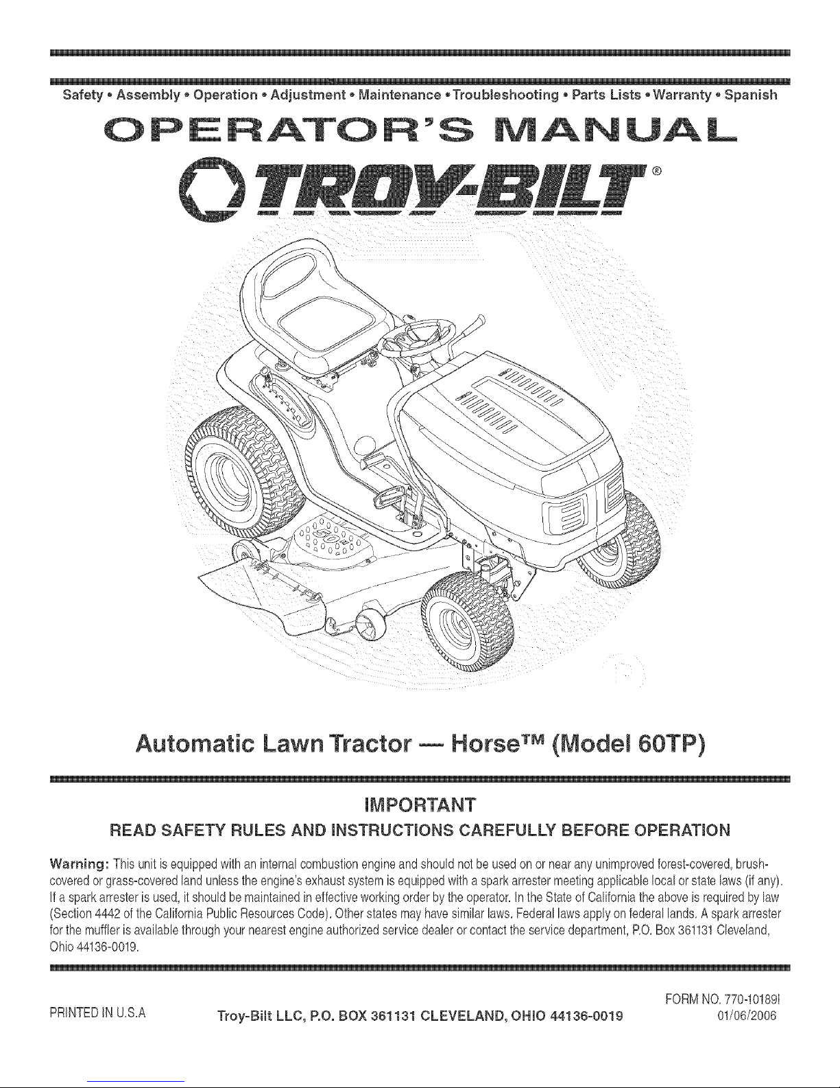
Automatic Lawn Tractor Horse TM(Model 60TP)
READ SAFETY RULES AND mNSTRUCTmONS CAREFULLY BEFORE OPERATmON
Warning: This unitis equippedwithan internalcombustionengineandshouldnotbeusedon or nearanyunimprovedforest-covered,brush=
coveredor grass=coveredlandunlesstheengine'sexhaustsystemis equippedwitha sparkarrestermeetingapplicablelocalorstatelaws(if any),
If a sparkarresterisused,it shouldbemaintainedineffectiveworkingorderbytheoperator,Inthe StateofCaliforniatheaboveis requiredbylaw
(Section4442ofthe CaliforniaPuNicResourcesCode),Otherstatesmayhavesimilarlaws,Federallawsapplyonfederallands,A sparkarrester
forthe mufflerisavailablethroughyournearestengineauthorizedservicedealeror contacttheservicedepartment,RO,Box361131Cleveland,
Ohio44136=0019,
PRINTEDIN U,S,A Troy-Bilt LLC, P.O. BOX 361131 CLEVELAND, OHIO 44136-0019 01/06/2006
FORMNO,770=10189I
Page 2
This Operator's Manua_ is an important part of your new lawn tractor, mtwH_ he_p you assemble,
prepare and maintain the unit for best performance. P_ease read and understand what it says.
Table of Contents
Slope Gauge ....................................................... 3
Safe Operation Practices ................................... 4
Setting Up Your Lawn Tractor ............................ 8
Operating Your Lawn Tractor ........................... 10
Adjusting Your Lawn Tractor ............................ 18
Finding and Recording Model Number
BEFOREYOU STARTASSEMBLING
YOURNEW EQUIPMENT,
please locatethe modelplate onthe equipmentand copythe
informationto the sample model plate providedto the righL
Youcan locatethe modelplate by looking beneath the seal
Thisinformationwill be necessaryto usethe manufacturer's
web siteand/or obtainassistancefromthe CustomerSupport
Departmentoran authorizedservice dealer.
Maintaining Your Lawn Tractor ........................ 20
Off-Season Storage / Attachments ................. 26
Safety Labels .................................................... 27
TrouMe Shooting .............................................. 28
Parts List ........................................................... 30
Modem Number Seriam Number
0 TR#_H_--T_ TROY=BiLT LLC
P. O. BOX 361131
www.troybiit.com CLEVELAND, ON44136
338=558=7228
,, 856=848=6483_
Customer Support
P_ease do NOTreturn the unitto the retai_er from which it was
purchased, without first contacting Customer Support.
if you havedifficulty assemblingthis productor haveany questions regarding the controls, operation, or maintenanceof this
unit,youcan seek helpfrom the expert& Choosefromthe optionsbelow:
1, Visittroybilt.com for manyusefulsuggestions,Clickon Customer
Supportbuttonandyouwillget theoptionsreproducedin thescreen
shotbelow,CIbk onthe appropriatebuttonandhelpis immediately
availabb,
2, Phonea Customer Support Representativeat 1=866-840=6483,
3, The engine manufacturer isresponsibbforall engine=relatedissues
with regardtoperformance,power=rating,specifications,warrantyand
service,Phaserefertothe enginemanufacturer'sOwner's/Operator's
Manual,packedseparatelywithyour unit,formoreinformation,
Page 3
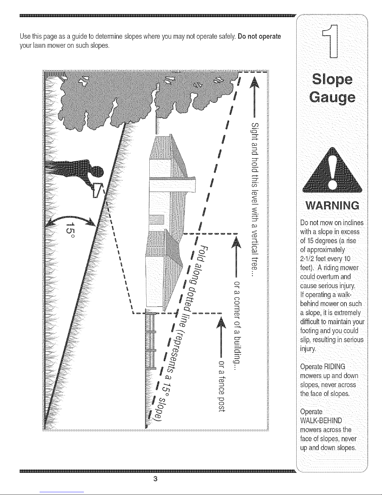
your lawn moweron such slopes.
/
t
/
/
/
/
/
o
WARNING
w_
Do not mowon inclines
with a dope in excess
of 15 degrees (a rise
of approximately
2-"
feet). A riding r
couldoverturnand
cause serious injury.
if operatinga walb
behindmoweron such
a dope, it is extremely
footing and you could
dip, resultinginserious
injury.
OperateRiDiNG
mowersupand down
dopes, neveracross
o
3
theface of dopes.
Operate
WALK-BEHIND
mowersacrossthe
face of dopes, never
up and down slopes.
\
Page 4
_i i _ i _i _ i _ iii _ _
S ale resultin seriousinjury.This machineis capable of amputatinghandsandfeet and throwing objects.
DANGER: This machine wasbuiltto be operatedaccordingto the rubs for safeoperation inthis
manuakAs withany type of powerequipment,carelessnessor erroronthe partof the operatorcan
Failureto observethe followingsafetyinstructionscould resultin serious injury or death.
instructionswhich, if
notfollowed, could
endangerthe personal
safetyand/or property
of yourself and others.
Readandfobowall
instructionsinthis man=
ualbefore attemptingto
operatethis machine.
Failureto complywith
Whenyouseethis
symbol.
HEED ITS WARNING
Your
Responsibility
Restrictthe use
of this power machine
to personswho read.
understand
and followthewarnings
and instructions
in this manual
Children
1. Tragicaccidentscanoccuriftheoperatorisnot
abrt tothepresenceof children.Childrenareoften
attractedto the machineandthemowingactivity.
Theydo notunderstandthe dangers.Neverassume
thatchildrenwillremainwhereyoulastsawthem.
a. Keepchildrenoutofthe mowingareaandin
watchfulcareof a responsibleadultotherthan
theoperator.
b. Bealertandturnmachineoffifachildenters
thearea.
c. Beforeandwhilebacking,lookbehindand
downfor smallchildren.
d. Nevercarrychildren,evenwiththeblade(s)
shutoff.Theymayfalloffandbeseriously
iniuredor interferewithsafemachineoperation.
e. Useextremecarewhenapproachingblind
corners,doorways,shrubs,treesor other
objectsthatmayblockyourvisionofa child
whomayruninto themachine.
f. Toavoid back-overaccidents, always
disengagethe cutting blade(s) before
shifting into Reverse.Ifequipped,the
"ReverseCaution Mode" should not be
usedwhen children or others are around.
g. Keepchildrenawayfromhotor running
engines.Theycansuffer burnsfroma hot
muffler.
h. Removekeywhenmachineisunattendedto
preventunauthorizedoperation.
2. Neverallowchildrenunder14yearsoldto operate
themachine.Children14}'earsoldandovershould
readandunderstandtheoperationinstructionsand
safetyrubs inthis manualandshouldbetrainedand
supervisedbya parent.
Operation
Safe Handlingof Gasoline:
1. Toavoid personal injuryor property damageuse
extremecare in handlinggasoline. Gasoline is
extremely flammableand the vapors areexplo-
sive. Seriouspersonaliniurycanoccurwhengasoline
isspilledonyourselforyourclotheswhichcan ignite.
Washyourskinandchangeclothesimmediately.
a. Useonlyanapprovedgasolinecontainer.
b. Neverfillcontainersinsideavehbb or ona
truckor trailerbedwitha plastb liner.Always
placecontainerson thegroundawayfrom
yourvehble beforefilling.
c. Whenpractbal,removegas-powered
equipmentfromthetruck ortrailerand refuelit
ontheground.Ifthis isnot possibb,then
refuelsuchequipmentona trailerwitha
portabbcontainer,ratherthanfromagasoline
dispensernozzb.
d. Keepthenozzbincontactwiththerimof
thefueltankor containeropeningatall
timesuntilfuelingis complete.Donot usea
nozzleIocbopendevice.
e. Extinguishallcigarettes,cigars,pipesand
othersourcesofignition.
f. Neverfuelmachineindoors.
g. Neverremovegascaporaddfuelwhilethe
engineishot or running.Mow engineto cool
atbast twominutesbeforerefueling.
h. Neveroverfillfueltank.Filltanktonomore
than1/2inchbelowbottomoffilbr neckto
allowspacefor fuelexpansion.
i. Replacegasolinecapandtightensecurely.
i. If gasolineisspilled,wipeitofftheengine
andequipment.Moveunittoanotherarea.
Wait5 minutesbeforestartingthe engine.
k. Toreducefirehazards,keepmachinefreeof
grass,leaves,orotherdebrisbuild-up.Clean
upoil orfuelspillageand removeanyfuel
soakeddebris.
I. Neverstorethemachineorfuelcontainer
insidewherethereis anopenflame,spark
or pilotlightason a waterheater,space
heater,furnace,clothesdryeror othergas
appliances.
m. Allowa machinetocool atbast fiveminutes
beforestoring.
4
Page 5
GeneralOperation:
1. Read,understand,andfollowallinstructionsonthe
machineandinthe manual(s)beforeattemptingto
assembleandoperate.Keepthismanualina safe
placeforfutureandregularreferenceandforordering
replacementparts.
2. Befamiliarwithall controlsandtheirproperoperation.
Knowhowtostopthe machineanddisengagethem
quickly.
3. Neverallowchildrenunder14yearsold to operate
this machine.Children14yearsold andovershould
readandunderstandtheoperationinstructionsand
safetyrubs in thismanualandshouldbetrainedand
supervisedbyaparent.
4. Neverallowadultstooperatethis machinewithout
properinstruction.
5. Tohelpavoidbladecontactora thrownobiectiniury,
keepbystanders,helpers,childrenandpetsat bast
75 feetfromthemachinewhileit is inoperation.8top
machineifanyoneentersthearea.
6. Thoroughlyinspecttheareawheretheequipmentisto
beused.Removeallstones,sticks,wire,bones,toys,
andotherforeignobiectswhichcould bepickedup
andthrownbythe blade(s).Thrownobiectscancause
seriouspersonaliniury.
7, Planyourmowingpatterntoavoiddischargeof
materialtowardroads,sidewalks,bystandersandthe
like.Also,avoiddischargingmaterialagainsta wall or
obstructionwhichmaycausedischargedmaterialto
ricochetbacktowardtheoperator.
8. Alwayswearsafetyglassesorsafetygogglesduring
operationandwhile performingan adiustmentor
repairtoprotectyoureyes.Thrownobiectswhich
ricochetcancauseseriousiniuryto theeyes.
9. Wearsturdy,rough-sobdworkshoesandclose-fitting
slacksandshirts.Loosefittingclothesandiewelry
canbecaughtinmovabbparts. Neveroperatethis
machinein barefeetor sandals.
10.Beawareofthe mowerandattachmentdischarge
directionanddo notpoint itat anyone.Donotoperate
themowerwithoutthedischargecoverorentiregrass
catcherin itsproperplace.
11.Donotput handsorfeetnearrotatingpartsor under
thecuttingdeck.Contactwiththe blade(s)can
amputatehandsandfeet.
12.Amissingor damageddischargecovercan cause
bladecontactor thrownobiectiniuries.
13.8toptheblade(s)whencrossinggraveldrives,walks,
or roadsandwhilenotcuttinggrass.
14.Watchfortrafficwhenoperatingnearorcrossing
roadways.Thismachineisnot intendedforuseon
anypublic roadway.
15.Donotoperatethemachinewhileunderthe influ-
enceof alcoholordrugs.
16.Mowonlyin daylightor goodartificiallight.
17,Nevercarrypassengers.
18.Disengageblade(s)beforeshiftingintoreverse.
Backupslowly.Alwayslookdownandbehindbefore
andwhilebackingto avoida back-overaccident.
19.Slowdownbeforeturning.Operatethe machine
smoothly.Avoiderraticoperationandexcessive
speed. }
20.Dbengageblade(s),setparkingbrake,stopengine
andwaituntilthe blade(s)cometo acompletestop
beforeremovinggrasscatcher,emptyinggrass,
uncloggingchute,removinganygrassor debris,or
makinganyadiustments.
21.Neverleavea runningmachineunattended.Always
turnoff blade(s),placetransmissionin neutral,set
parkingbrake,stopengineand removekeybefore
dismounting.
22.Useextracare whenloadingor unloadingthe
machineintoa trailerortruck.Thisunitshould not
bedrivenupor downramp(s),becausethe unit
couldtip over,causingseriouspersonaliniury.The
unitmustbepushedmanuallyonramp(s)to loador
unloadproperly.
23.Mufflerandenginebecomehotandcan causea
burn.Do nottouch.
24.Checkoverheadclearancescarefullybeforedriving
underlowhangingtreebranches,wires,dooropen-
ingsetc. wheretheoperatormaybestruckorpulled
fromtheunit,whichcouldresultinseriousiniury.
25.Disengageallattachmentclutches,depressthe
brakepedalcompbtelyandshift intoneutralbefore
attemptingtostartengine.
26.Yourmachineisdesignedtocutnormalresidential
grassof aheightno morethan 10".Donotattemptto
mowthroughunusuallytall,dry grass(e.g.,pasture)
or pilesof dryleaves.Drygrassor leavesmay
contacttheengineexhaustand/orbuildup onthe
mowerdeckpresentinga poten%lfire hazard.
27.Useonlyaccessoriesandattachmentsapprovedfor
thismachinebythe machinemanufacturer.Read,
understandandfollowall instructionsprovidedwith
theapprovedaccessoryorattachment.
28.Dataindicatesthatoperators,age60 yearsand
above,areinvolvedin a largepercentageofriding
mower-relatediniuries.Theseoperatorsshould
evaluatetheirabilityto operatetheridingmower
safelyenoughto protectthemselvesandothersfrom
seriousiniury.
29.Ifsituationsoccurwhicharenot coveredinthis
manual,usecareandgoodiudgment.Contactyour
customerservicerepresentativeforassistance.
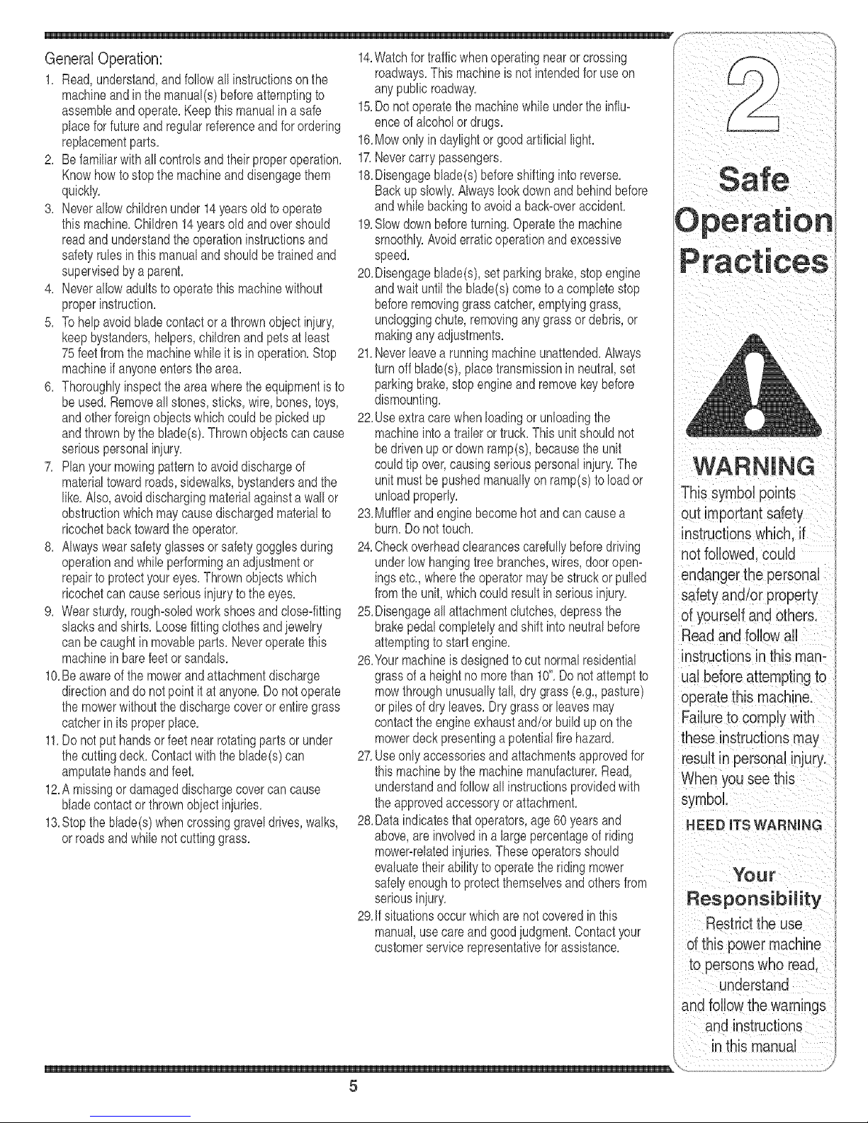
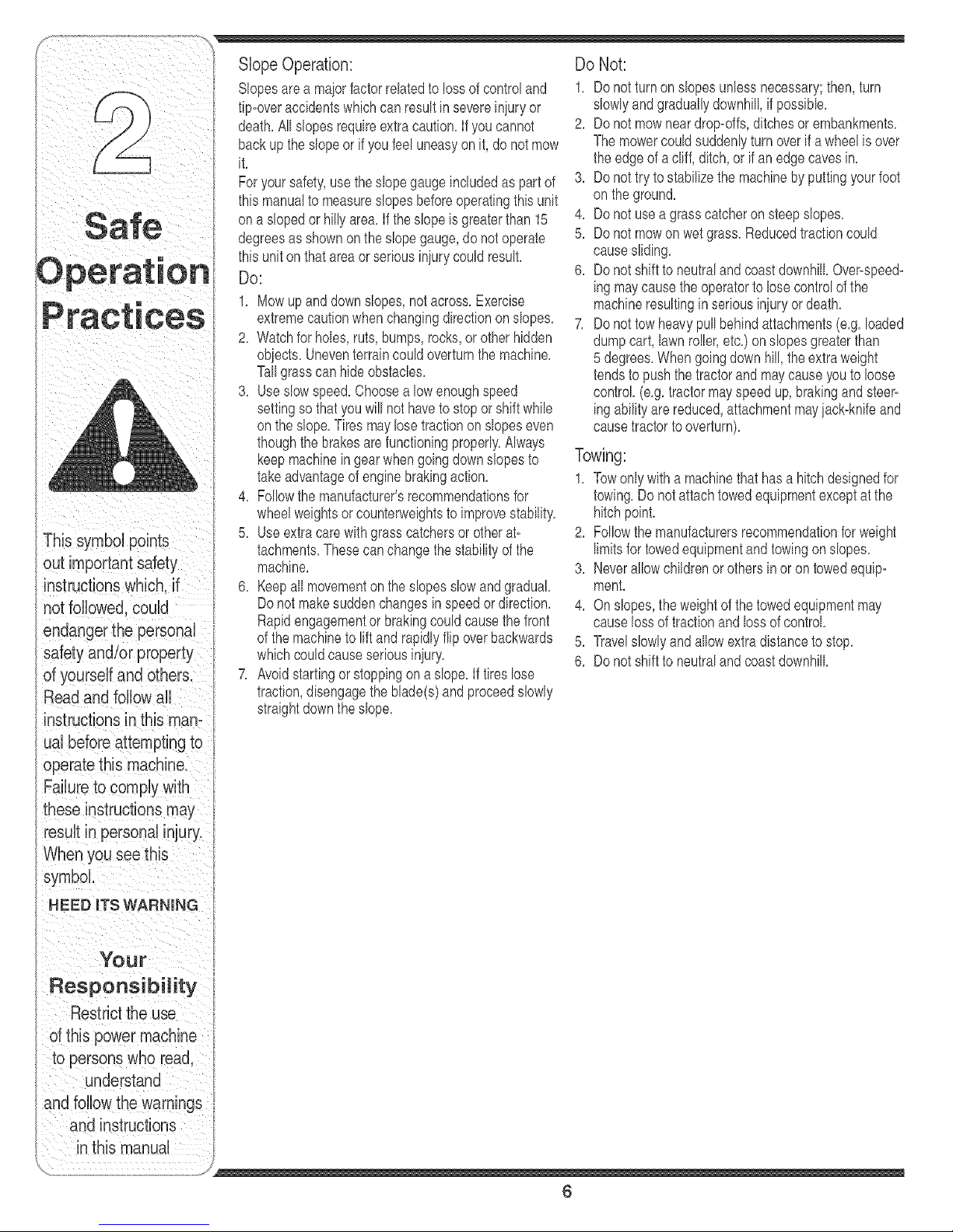
WARNING
Thissymbol points
instructionswh ch. if
notfollowed,could
endangerthe personal
safety and/or property
of yourself and others.
Readand followall
instructionsin this man-
ual before attemptingto
operatethis machine.
these instructions may
result in personal injury.
When you see this
symbol.
HEED iTS WARNING
Your
Responsibility
Restrictthe use
d this powermachine
to personswho read,
understand
and followthe warninas
and instructions
in this manual
5
Page 6
Slope Operation:
Slopesarea majorfactorrelatedtolossof controland
tip-overaccidentswhichcanresultin severeinjuryor
death,All slopesrequireextracaution,if youcannot
backuptheslopeor ifyoufeeluneasyonit, do notmow
it,
Foryour safety,usetheslopegaugeincludedaspartof
thismanualto measureslopesbeforeoperatingthisunit
ona slopedor hillyarea,if theslopeisgreaterthan15
;_,_ degreesasshownontheslopegauge,do notoperate
,, thisunitonthatareaorseriousinjurycouldresult,
uperal:lon Do:
1, Mowupanddownslopes,notacross,Exercise
racl:lces extremecautionwhenchangingdirectiononsbpes,
2, Watchforhobs, ruts,bumps,rocks,or otherhidden
objects,Uneventerraincouldoverturnthemachine,
Tallgrasscan hideobstacbs,
3, Useslowspeed,Choosea lowenoughspeed
settingso thatyouwill nothaveto stoporshift while
ontheslope,Tiresmaylosetractiononslopeseven
thoughthe brakesarefunctioningproperly,Always
keepmachineingearwhengoingdownslopesto
takeadvantageofenginebrakingaction,
4, Followthemanufacturer'srecommendationsfor
wheelweightsorcounterweightsto improvestability,
5, Useextracarewithgrasscatchersorotherat-
out important safety
instructionswhich,if
notfollowed,could
endangerthe personal
safety and/or property
of yourself and others.
Readand follow all
instructionsin this man°
ual before attemptingto
tachments,Thesecanchangethestabilityof the
machine,
6, Keepall movementon theslopesslowandgradual
Donot makesuddenchangesinspeedor direction,
Rapidengagementor brakingcouldcausethe front
ofthe machineto liftand rapidlyfib overbackwards
whichcouldcauseseriousinjury,
7, Avoidstartingor stoppingon a slope,If tireslose
traction,disengagetheblade(s)andproceedslowly
straightdowntheslope,
Do Not:
1, Donotturnonslopesunlessnecessary;then,turn
slowlyandgraduallydownhill,if possibb,
2, Donotmowneardrop-offs,ditchesorembankments,
Themowercouldsuddenlyturnoverif awheel isover
theedgeof acliff,ditch,or if anedgecavesin,
3, Donottry tostaNlizethemachinebyputtingyourfoot
ontheground,
4, Donotuseagrasscatcheronsteepslopes,
5, Donotmowonwetgrass,Reducedtractioncould
causesliding,
6, DonotshifttoneutralandcoastdownhillOver-speed-
ingmaycausetheoperatortolose controlofthe
machineresultingin seriousinjuryordeath,
7, Donottow heavypullbehindattachments(e,g,loaded
dumpcart, lawnroller,etc,)on slopesgreaterthan
5 degrees,Whengoingdown hill,the extraweight
tendsto pushthetractorand maycauseyouto loose
control (e,g,tractormayspeedup,brakingandsteer-
ingabilityarereduced,attachmentmayjack-knifeand
causetractorto overturn),
Towing:
1, Towonlywitha machinethathasa hitchdesignedfor
towing,Donotattachtowedequipmentexceptatthe
hitchpoint,
2, Followthemanufacturersrecommendationfor weight
limitsfor towedequipmentandtowingonslopes,
3, Neverallowchildrenor othersin oron towedequip-
ment,
4, Onslopes,theweightofthetowedequipmentmay
causelossoftractionandlossofcontrol,
5, Travelslowlyandallowextradistancetostop,
6, Donotshifttoneutralandcoastdownhill
these instructions may
result in personal injury,
When you see this
symbol
HEED ITS WARNING
YOUr
Responsibility
Restrictthe use
ofthis power machine
to personswho read.
understand
and followthe warnings
and instructions
in this manual
6
Page 7
Service lO,Neverattemptto makeadiustmentsor repairstothe
1. Neverrun anengineindoorsorinapoorlyventilated
area.Engineexhaustcontainscarbonmonoxide,an
odorless,anddeadlygas.
2. Beforecleaning,repairing,orinspecting,makecertain
theblade(s)andall movingpartshavestopped.
Disconnectthe sparkplugwireandgroundagainstthe
engineto preventunintendedstarting.
3. Periodicallychecktomakesurethebladescometo
compbtestopwithinapproximately(5) fiveseconds
afteroperatingthebladedisengagementcontrol,ifthe
bladesdonotstopwithinthethis timeframe,yourunit
shouldbeservicedprofessionallybyanauthorized
MTDServiceDealer.
4. Checkbrakeoperationfrequentlyas itissubiectedto
wearduringnormaloperation.Adiustandserviceas
required.
5. Checktheblade(s)andenginemountingboltsat
frequentintervalsforpropertightness.Also,visually
inspectblade(s)fordamage(e.g. excessivewear,
bent,cracked). Replacetheblade(s)withtheoriginal
equipmentmanufacturer's(O.E.M.)blade(s)only,
listedin thismanual."Useof partswhichdonotmeet
theoriginalequipmentspecificationsmaybad to
improperperformanceandcompromisesafety!"
6. Mowerbladesaresharp.Wrapthe bladeor wear
gloves,anduseextracautionwhenservicingthem.
7, Keepall nuts,bolts,andscrewstightto besurethe
equipmentis insafeworkingcondition.
8. Nevertamperwiththe safetyinterlocksystemor other
safetydevices.Checktheir properoperationregularly.
9. Afterstrikingaforeignobiect,stoptheengine,
disconnectthesparkplugwire(s)and groundagainst
theengine.Thoroughlyinspectthe machineforany
damage.Repairthedamagebeforestartingand
operating,
machinewhiletheengineisrunning,
11,Grasscatchercomponentsandthedischarge
coveraresubiectto wearanddamagewhichcould
exposemovingpartsor allowobiectstobethrown,
Forsafetyprotection,frequentlycheckcomponents
andreplaceimmediatelywithoriginalequipment
manufacturer's(O,E,M,)partsonly,listedinthis
manual,"Useof partswhichdo notmeettheoriginal
equipmentspecificationsmaybad toimproper
performanceandcompromisesafety!"
12,Donotchangetheenginegovernorsettingsor
over-speedtheengine,Thegovernorcontrolsthe
maximumsafeoperatingspeedof theengine,
13,Maintainor replacesafetyandinstructionlabels,as
necessary,
14,Observeproperdisposallawsandregulationsfor
gas,oil,etc, toprotecttheenvironment,
ii
i /
This symbol points
instructionswhich, if
safetyand/or property
ofyourself and others,
Readand follow al
ual before attemptingto
operatethis machine.
When you see this
symbol,
NEED roTSWARNING
Your
Responsibility
Restrictthe use
of this power machine
to personswho read,
understand
>wthewarnings
and instructions
in this manual
\
7
Page 8

Use extremecare
gasoline. Gasol!ne is
extremely flammab!e
andtheVaporsare
explos!ve. Never fuel
machine indoors
orwhiletheengine
is hot or running.
Ext ,g, shcigarettes,
Wini Nut
Hex Bolt
Figure 1
Attaching the Battery Cables
NOTE:Thepositivebatteryterminalis markedPos,(+),
The negativebatteryterminalis markedNeg,(-),
Thepositivecable(heavyredwire) issecuredto the
positivebatteryterminal(+)withahexboltandhex
nutat thefactory.Beforeattachingthenegativecable
removethebatterybyremovingthepositivecable
andhold=downstrap.Notethe dateon thesideof the
battery,ifthe batteryis putinto serviceafterthisdate,
chargethebatteryas instructedon page22 ofthis
manualpriorto operatingthetractor.
. Securebatterybackontothetractorwiththehold=
downstrap.Reattachthepositivecable(heavyred
wire)to thepositivebatteryterminal(+)withthebolt
andnut.Makecertainthattherubberbootcoversthe
terminalto helpprotectit fromcorrosion.
• Removethehex boltandhexnutfromthe negative
cable.
• Removetheblackplasticcover,if present,fromthe
negativebatteryterminalandattachthenegative
cable(heavyblackwire)tothe negativebattery
terminal(-) withthe boltandnut.
• Makecertainthehold=downstrapisin positionover
thebattery,securingit inplace,SeeFigure1,
Gas and Oil Fill-up
Thegasolinetankislocatedunderthe hoodandhasa
capacityofthreegallons,Donotoverfill,
WARNING: Use extreme care
when handling gasoline. Gasoline
is extremely flammable and the
vapors are explosive. Never fuel
machine indoorsor while the
engine is hotor running. Extin-
guish cigarettes, cigars, pipes,
and other sources of ignition.
8
Page 9
Servicetheenginewith gasolineandoilasinstructedin f
theseparateKohlerOperator/OwnerManualpackedwith
yourtractor,Readinstructionscarefully,
IMPORTANT:Yourtractorisshippedwithmotoroilinthe
engine,However,you MUSTchecktheoillevel before
operating,Becarefulnotto overfill,
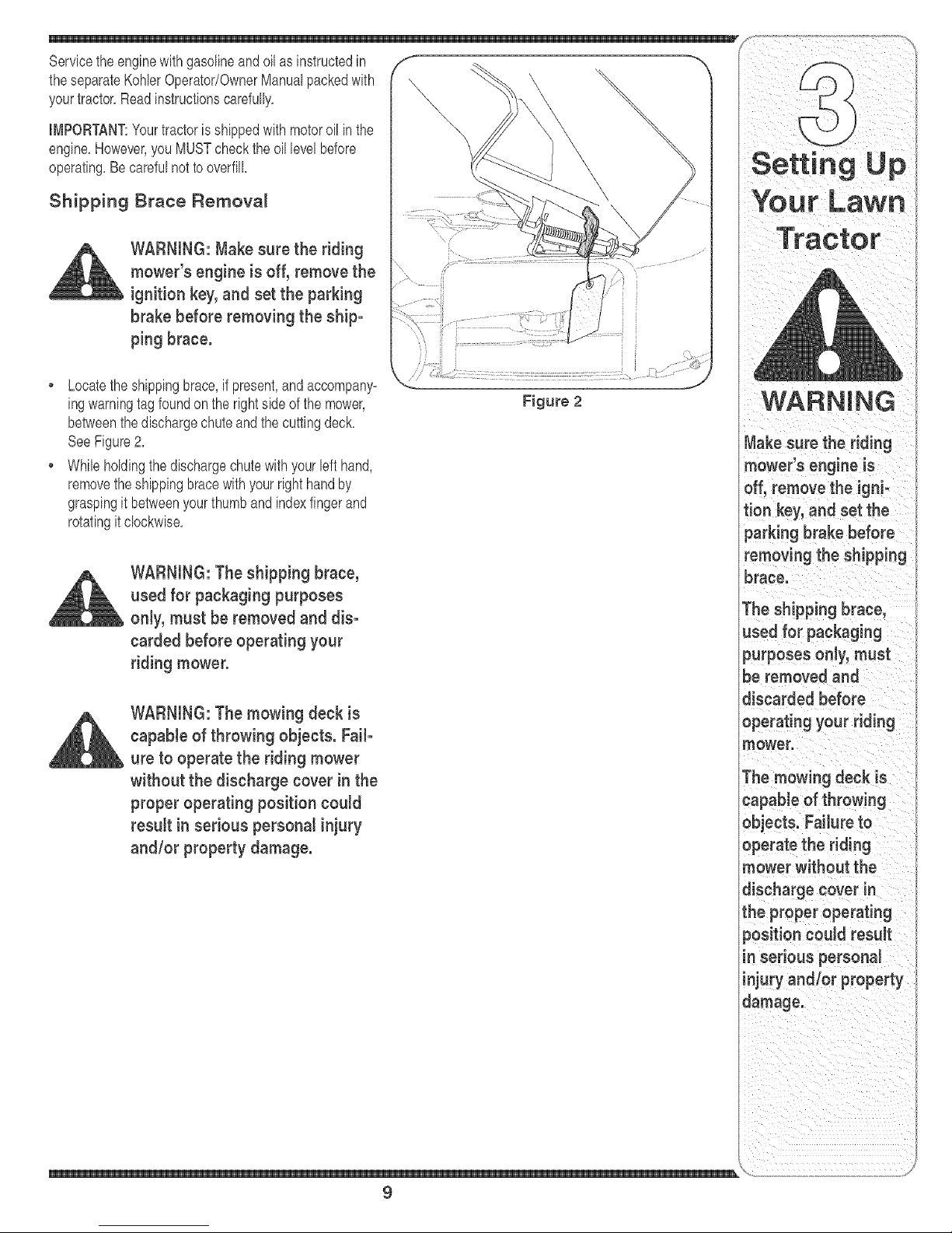
Shipping Brace Remova_
WARNING: Make sure the riding
mower's engine is off, remove the
ignitionkey, and set the parking
brake before removing the ship-
ping brace.
Locatetheshippingbrace,ifpresent,andaccompany-
ingwarningtagfoundon the rightside ofthe mower,
betweenthedischargechuteandthe cuttingdeck,
SeeFigure2,
• While holdingthedischargechutewithyourleft hand,
removetheshippingbracewithyourrighthandby
graspingit betweenyourthumbandindexfingerand
rotatingitclockwise,
WARNING: The shipping brace,
used for packaging purposes
only, must be removed and dis-
carded before operating your
riding mower.
WARNING: The mowing deck is
capable of throwing objects. Fail-
ure to operate the riding mower
without the discharge cover in the
proper operating position could
result in serious personal injury
and/or property damage.
Figure 2
Your Lawn
Tractor
WARNING
Make sure the riding
mower's engine is
off, remove the igni-
tion key, and set the
parking brake before
removing the shipping
brace.
The shipping brace,
used for packaging
purposes only, must
be removed and
discarded before
operating your riding
mower.
The mowing deck is
capable of throwing
objects. Failure to
operate the riding
mower without the
discharge cover in
the proper operating
9
Page 10
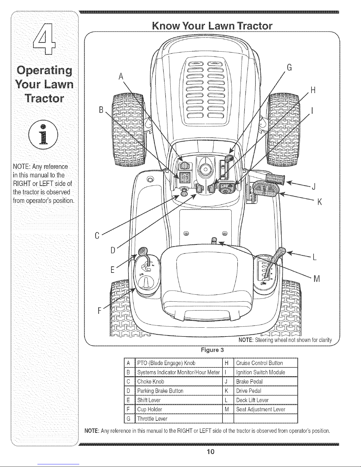
NOTE:Anyreference
inthismanualtothe
RIGHTorLEFTsideof
Know Your Lawn Tractor
G
A
@
J
@ @
D
E
A PTO(BladeEngage)Knob H CruiseControISutton
B SystemslndicatorMonitor/HourMeter I ignitionSwitchModule
C ChokeKnob J BrakePedal
D ParkingBrakeButton K DrivePedal
E ShiftLever L DeckLift Lever
F CupHolder M SeatAdiustmentLever
G Throttb Lever
K
M
NOTE:Anyreferencein thismanualtotheRIGHTor LEFTside ofthe tractoris observedfromoperator'sposition,
J
10
Page 11
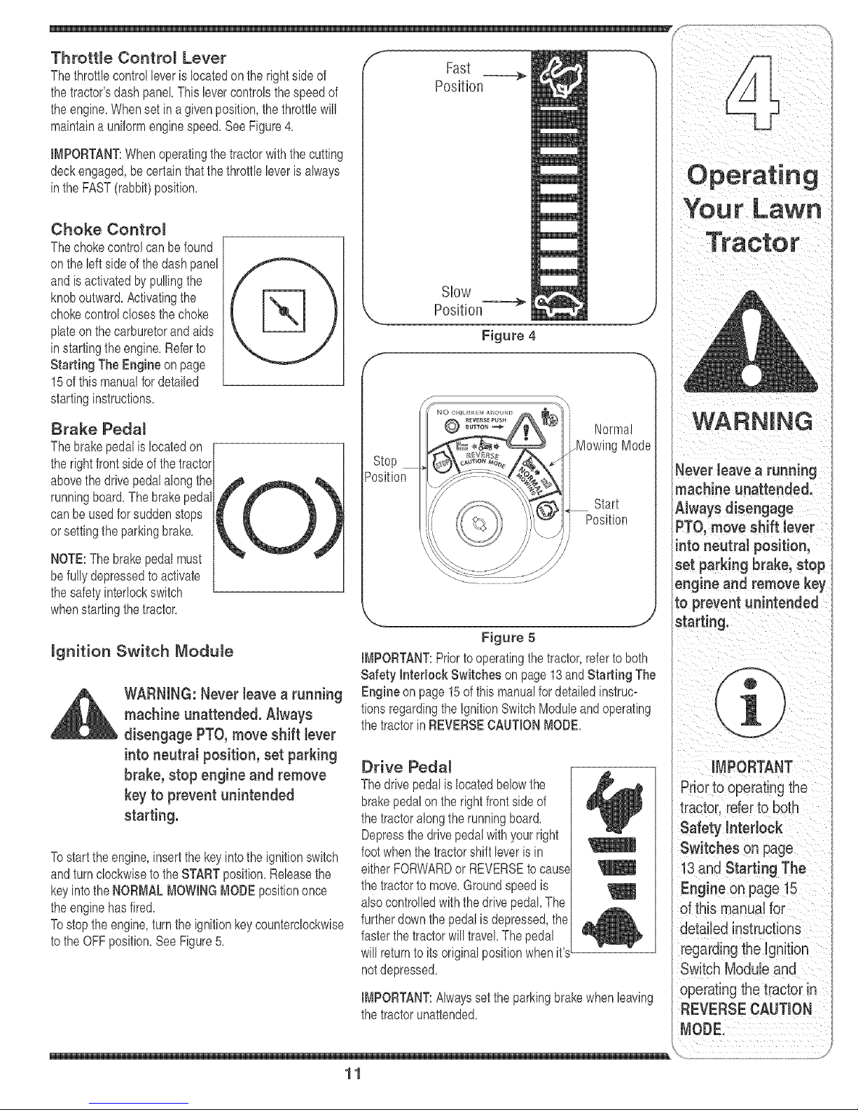
theengine.Whensetin agiven position,thethrottlewill
maintaina uniformenginespeed.SeeFigure4.
IMPORTANT:Whenoperatingthetractorwiththecutting
deckengaged,becertainthatthe throttb bver isalways
inthe FAST(rabbit)position.
Choke Contro_
Thechokecontrolcan befound
onthebft sideofthedashpanel
andisactivatedby pullingthe
knoboutward.Activatingthe
chokecontrolclosesthe choke
plateonthe carburetorandaids
instartingthe engine.Referto
Starting TheEngine onpage
15ofthis manualfordetailed
startinginstructions.
Slow
Position---=_
Figure 4
Brake Pedal
Thebrakepedalislocatedon [
therightfrontsideof thetractor/
abovethedrivepedalalongthe-
runningboard.Thebrakepedal
canbeusedforsuddenstops
orsettingthe parkingbrake.
NOTE:Thebrakepedalmust
befullydepressedtoactivate
thesafetyinterlockswitch
whenstartingthetractor.
mgnition Switch Module
WARNING: Never have a running
machine unattended. AJways
disengage PTO,move shift bver
into neutral position, set parking
brake, stop engine and remove
key to prevent unintended
starting.
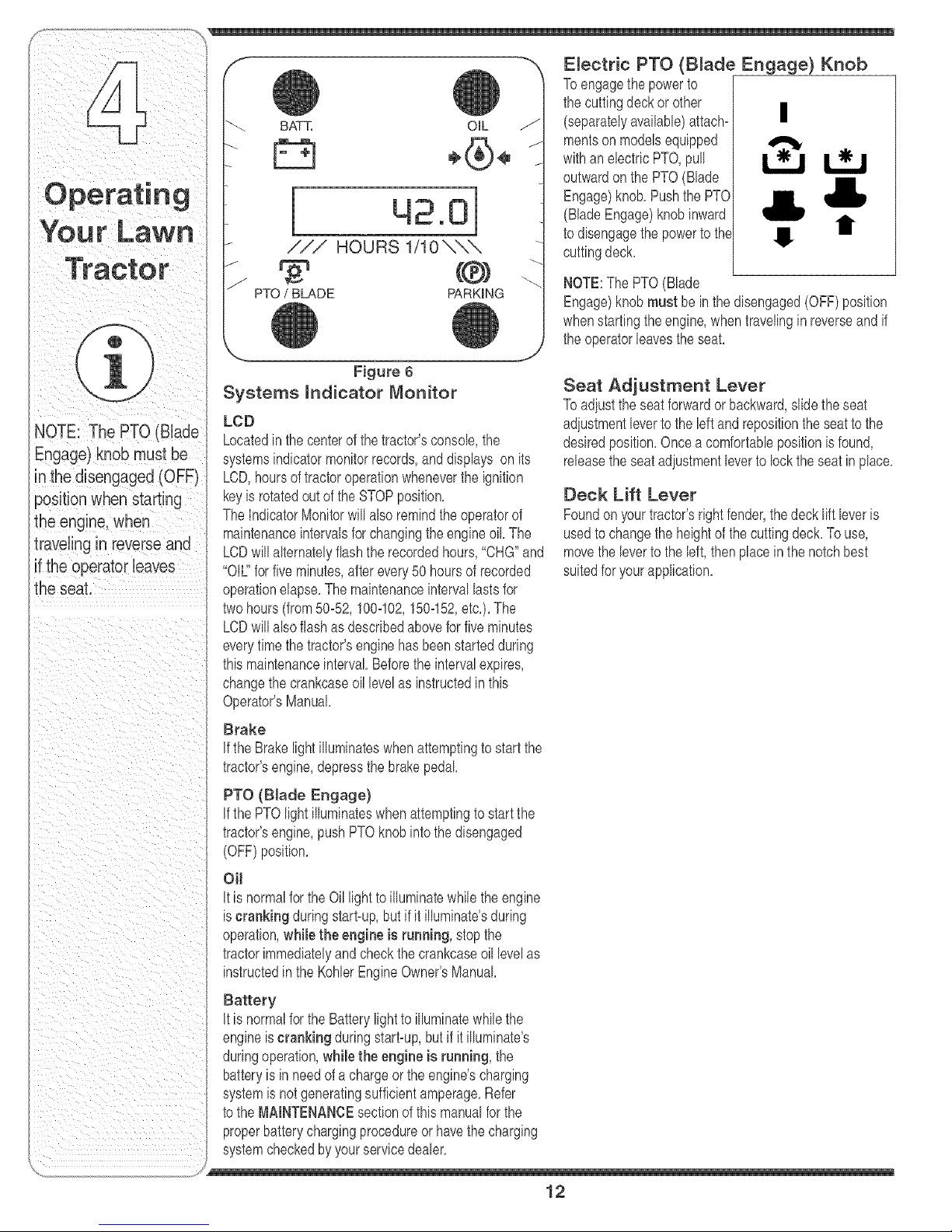
Tostarttheengine,insertthe keyintothe ignitionswitch
andturnclockwiseto theSTARTposition.Rebasethe
keyintothe NORMALMOWINGMODEpositiononce
theenginehasfired.
Tostopthe engine,turnthe ignitionkeycounterclockwise
tothe OFFposition.SeeFigure5.
Normal
_MowingMode
_osition
Start
Position
Figure 5
IMPORTANT:Priortooperatingthetractor,referto both
Safety hterlock Switches on page13andStarting The
Engineon page15ofthis manualfordetailedinstruc=
tionsregardingtheignitionSwitchModuleandoperating
thetractorin REVERSECAUTIONMODE.
Drive Pedal
Thedrivepedalislocatedbelowthe
brakepedalonthe rightfrontside of
thetractoralongtherunningboard.
Depressthe drivepedalwithyourright
footwhenthe tractorshift bver is in
eitherFORWARDor REVERSEtocause
thetractortomove.Groundspeedis
alsocontrolledwiththe drb'epedal.The
furtherdownthe pedalisdepressed,the
fasterthe tractorwilltravel Thepedal
willreturntoits originalpositionwhenit'sL
notdepressed.
IMPORTANT:Alwayssettheparkingbrakewhenleaving
thetractorunattended.
machine unattended.
A ,vaysd sengage
PTO, move Shift lever
into neutral position,
set parking brake;stop
engineandremovekey
to prevent unintended
stai
operating the tractor in
REVERSE CAUTION
11
Page 12
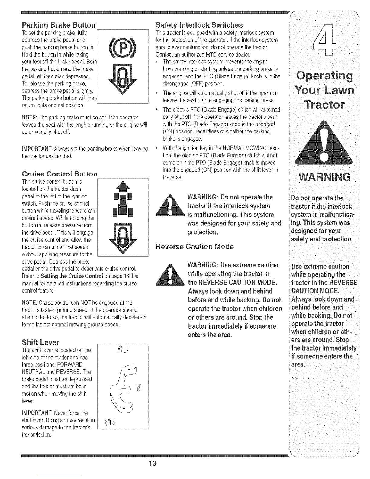
NOTE:The PTo (Biade
Engage)knobmust be
inthedisengaged(OFF)
the seat.
BATT, OIL
/
/
/
.ol
/
Systems mndicator Monitor
LeD
Locatedinthecenterof thetractor'sconsole,the
systemsindicatormonitorrecords,anddisplays on its
LCD,hoursoftractoroperationwheneverthe ignition
keyb rotatedoutof theSTOPposition,
TheIndicatorMonitorwillalso remindtheoperatorof
maintenanceintervalsforchangingtheengineoil The
LCDwillalternatelyflashtherecordedhours,"CHG"and
"Oil" for fiveminutes,afterevery50 hoursof recorded
operationelapse,The maintenanceintervallastsfor
twohours(from50-52,100-102,150-152,etc,),The
LCDwillalsoflashasdescrbed aboveforfiveminutes
everytimethetractor'senginehasbeenstartedduring
thb maintenanceinterval Beforetheintervalexpires,
changethecrankcaseoil levelas instructedin this
Operator'sManual,
Brake
If theBrakelightilluminateswhenattemptingtostartthe
tractor'sengine,depressthebrakepedal
/// HOURS 1/10\\\
PTO/ BLADE PARKmNG
Figure 6
Electric PTO (B_ade Engage) Knob
Toengagethe powerto
thecuttingdeckor other
(separatelyavailable)attach- |
mentsonmodelsequipped
withanelectricPTO,pull
outwardon thePTO(Blade
Engage)knob,Pushthe PTO
(BladeEngage)knobinward
todisengagethepowertothe t
cuttingdeck,
NOTE:ThePTO(Blade
Engage)knobmust bein thedisengaged(OFF)position
whenstartingtheengine,whentravelinginreverseandif
theoperatorleav'estheseat,
Seat Adjustment Lever
Toadiustthe seatforwardor backward,slidethe seat
adiustmentleverto theleftandrepositiontheseattothe
desiredposition,Oncea comfortabbpositionisfound,
releasetheseatadiustmentleverto locktheseat inplace,
Deck Lift Lever
Foundonyourtractor'srightfender,thedecklift leveris
usedto changethe heightofthecuttingdeck,Touse,
movethebver tothe left,thenplacein the notchbest
suitedforyourapplication,
I!
PTO (Blade Engage)
if the PTOlightilluminateswhenattemptingtostart the
tractor'sengine,pushPTOknobintothedisengaged
(OFF)position,
OH
it is normalfortheOil lighttoilluminatewhiletheengine
iscranking duringstart-up,but ifit illuminate'sduring
operation,while the engine is running, stopthe
tractorimmediatelyandcheckthecrankcaseoillevelas
instructedin theKohlerEngineOwner'sManual
Battery
it is normalfortheBatterylightto illuminatewhilethe
engineiscranking duringstart-up,but if it illuminate's
duringoperation,while the engine is running, the
batteryis in needofa chargeortheengine'scharging
systemis notgeneratingsufficientamperage,Refer
tothe MAINTENANCEsectionofthis manualforthe
properbatterychargingprocedureorhavethecharging
systemcheckedbyyourservmedealer,
/
12
Page 13
Parking Brake Button
Tosetthe parkingbrake,fully
depressthe brakepedaland
pushthe parkingbrakebuttonin,
Holdthe buttoninwhiletaking
yourfootoff thebrakepedal Both"
theparkingbuttonandthe brake
pedalwillthen staydepressed,
Toreleasethe parkingbrake,
depressthe brakepedalslightly,
Theparkingbrakebuttonwill ther
returnto itsoriginalposition,
NOTE:Theparkingbrakemustbesetif theoperator
leavestheseatwiththe enginerunningor theenginewill
automaticallyshutoff,
IMPORTANT:Alwayssettheparkingbrakewhenleaving
thetractorunattended,
Cruise Contro_ Button
Thecruisecontrolbuttonis
locatedonthetractordash
paneltothe leftofthe ignition
switch,Pushthecruisecontrol
buttonwhiletravelingforwardat a
desiredspeed,Whileholdingthe
buttonin,releasepressurefrom
thedrivepedal Thiswillengage
thecruisecontrolandallowthe
tractorto remainatthatspeed
withoutapplyingpressuretothe
drivepedal Depressthebrake
pedalor thedrivepedalto deactivatecruisecontrol
RefertoSetting the Cruise Control on page16this
manualfordetailedinstructionsregardingthecruise
controlfeature,
NOTE:Cruisecontrolcan NOTbe engagedatthe
tractor'sfastestgroundspeed,if theoperatorshould
attempttodoso,the tractorwill automaticallydecelerate
tothe fastestoptimalmowinggroundspeed,
Shift Lever
Theshift leveris locatedon the
leftsideof thefenderand has
threepositions,FORWARD,
NEUTRALand REVERSE,The
brakepedalmustbe depressed
andthetractormustnot bein
motionwhenmovingthe shift
lever,
uu _
Thistractoris equippedwith asafetyinterlocksystem
forthe protectionof theoperator,Ifthe interlocksystem
shouldevermalfunction,do notoperatethetractor,
Contactan authorizedMTDservicedealer,
, Thesafetyinterlocksystempreventstheengine
fromcrankingor startingunlessthe parkingbrakeis
engaged,andthe PTO(BladeEngage)knobisinthe
disengaged(OFF)position,
, Theenginewillautomaticallyshutoff if theoperator
leavestheseatbeforeengagingtheparkingbrake,
• The electricPTO(BladeEngage)clutchwillautomati-
callyshutoff ifthe operatorleavesthetractor'sseat
withthePTO(BladeEngage)knobinthe engaged
(ON)position,regardlessofwhetherthe parking
brakeis engaged,
, WiththeignitionkeyintheNORMALMOWINGposi-
tion,theelectricPTO(BladeEngage)clutchwillnot
comeonif the PTO(BladeEngage)knobismoved
intotheengaged(ON)positionwiththe shiftleverin
Reverse,
WARNING: Do not operate the
tractor if the interlock system
is malfunctioning. This system
was designed for your safety and
protection.
Reverse Caution Mode
WARNING: Use extreme caution
while operating the tractor in
the REVERSECAUTIONMODE.
Always took down and behind
before and while backing. Do not
operate the tractor when children
or others are around. Stop the
tractor immediately if someone
enters the area.
Tractor
l
=aution
while operating the
tractor in the REVERSE
Always look down and
behind before and
whi!e back!rig, Donot
operate the tractor
when children or oth:
ers are around. Stop
the tractor immediately
ifsomeone enters the
IMPORTANT:Neverforcethe
shiftlever,Doingsomayresultin
seriousdamagetothetractor's
transmission,
_,o iiiiiiiiiiiiiii _/
13
Page 14
De not operate the
tractor if the interlock
system is malfunction-
ing. This system was
designed for your
safety and protection.
Position
Start
Position
J
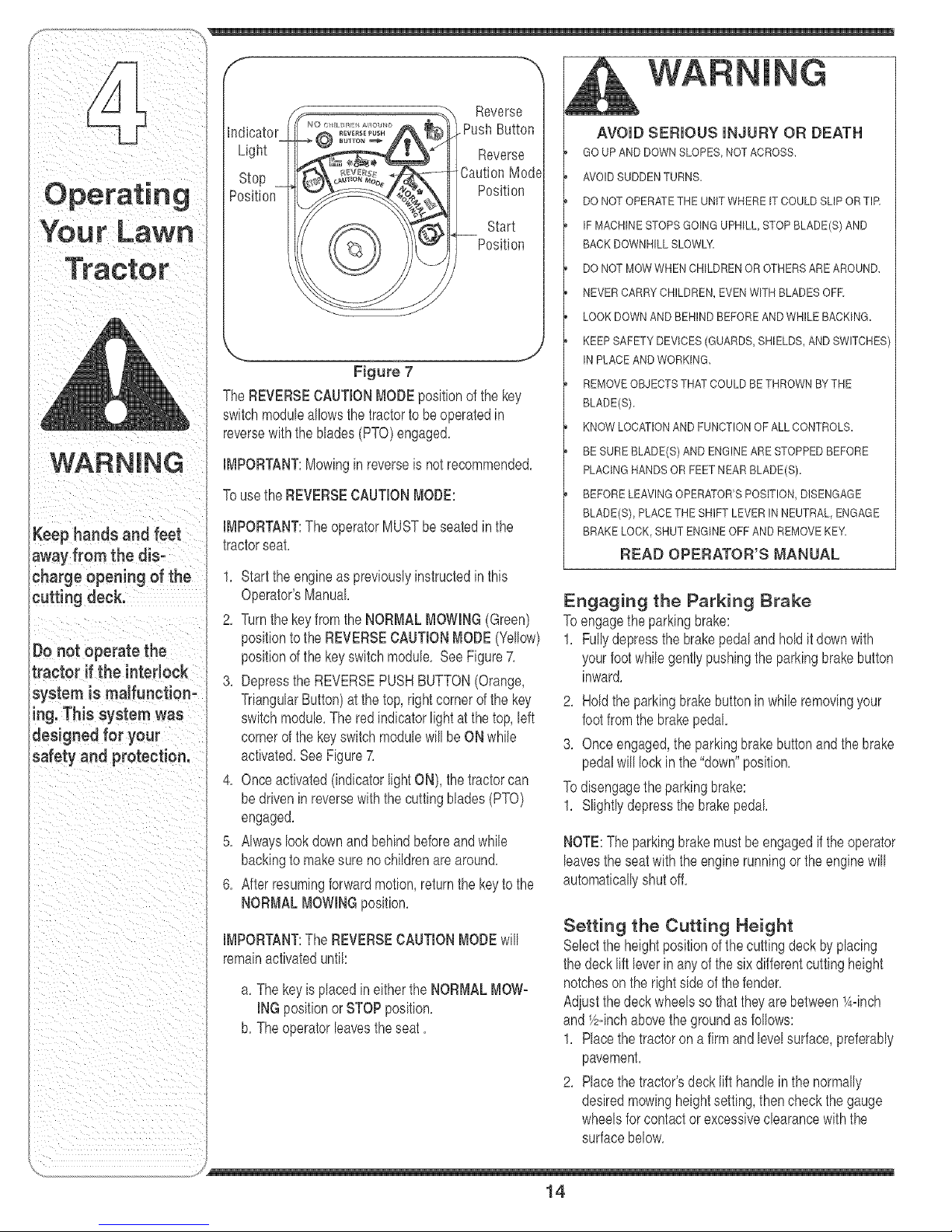
Figure 7
TheREVERSECAUTIONMODEpositionof the key
switchmoduleallowsthe tractorto beoperatedin
reversewiththeblades(PTO)engaged,
IMPORTANT:Mowingin reverseis notrecommended,
Tousethe REVERSECAUTIONMODE:
IMPORTANT:TheoperatorMUSTbeseatedinthe
tractorseat,
1, Startthe engineaspreviouslyinstructedinthis
Operator'sManual
2, Turnthekeyfromthe NORMALMOWING(Green)
positiontothe REVERSECAUTIONMODE(Yellow)
positionofthe keyswitchmodule, SeeFigure7,
3, DepresstheREVERSEPUSHBUTTON(Orange,
TriangularButton)atthetop,rightcornerof thekey
switchmodule,Thered indicatorlightatthe top,left
cornerof thekeyswitchmodulewillbeON wMe
activated,SeeFigure7,
4, Onceactivated(indicatorlightON), thetractorcan
bedrivenin reversewiththe cuttingblades(PTO)
engaged,
5, AMayslookdownandbehindbeforeandwMe
backingtomakesure nocMdrenarearound,
6, Afterresumingforwardmotion,returnthekeyto the
NORMALMOWINGposition,
IMPORTANT:TheREVERSECAUTIONMODEwill
remainactivateduntil:
a, The keyis placedin eitherthe NORMALMOW-
INGpositionorSTOPposition,
b, Theoperatorleavestheseat,
AVOIDSUDDENTURN&
DO NOT OPERATETHEUNITWHEREIT COULDSLIPORTIR
IFMACHINESTOPSGOINGUPHILL,STOPBLADE(S)AND
BACKDOWNHILLSLOWLY
DO NOT MOWWHENCHILDRENOROTHERSAREAROUND,
NEVERCARRYCHILDREN,EVENWITH BLADESOFE
LOOK DOWNAND BEHINDBEFOREAND WHILEBACKING.
KEEPSAFETYDEVICES(GUARDS,SHIELDS,ANDSWITCHES
INPLACEANDWORKING,
REMOVEOBJECTSTHATCOULDBE THROWNBYTHE
BLADE(Sb
KNOWLOCATIONANDFUNCTIONOF ALLCONTROLS.
BE SUREBLADE(S) ANDENGINEARESTOPPEDBEFORE
PLACINGHANDSORFEETNEAR BLADE(Sb
BEFORELEAVINGOPERATOR'SPOSITION,DISENGAGE
BLADE(S), PLACETHESHIFT LEVER IN NEUTRAL,ENGAGE
BRAKELOCK,SHUTENGINEOFFAND REMOVEKEY_
READ OPERATOR'S MANUAL
Engaging the Parking Brake
Toengagethe parkingbrake:
1, Fullydepressthebrakepedaland holdit downwith
yourfootwMe gentlypushingtheparkingbrakebutton
inward,
2, Holdtheparkingbrakebuttoninwhileremovingyour
footfromthe brakepedal,
3, Onceengaged,theparkingbrakebuttonandthebrake
pedalwilllockin the "down"position,
Todisengagetheparkingbrake:
1, Slightlydepressthebrakepedal
NOTE:Theparkingbrakemustbeengagedif theoperator
leavestheseatwiththe enginerunningor theenginewill
automaticallyshutoff,
Setting the Cutting Height
Selecttheheightpositionofthe cuttingdeckbyplacing
thedeckliftleverin anyof thesix differentcuttingheight
notchesonthe rightsideofthe fender,
Adjustthedeckwheelsso thattheyare between_A=inch
and_/zqnchabovethe groundasfollows:
1, Placethetractoronafirmandlevelsurface,preferably
pavement,
2, Placethetractor'sdecklift handleinthe normally
desiredmowingheightsetting,thencheckthegauge
wheelsforcontactorexcessiveclearancewiththe
surfacebelow,
J
14
Page 15
if the wheelscontactthesurfaceadiustasfollows: IMPORTANT:DoNOTholdthekeyintheSTARTpod=
3, Raisethedecklifthandletoits highestsetting,
4, Removethe reargaugewheelsbyremovingthe lock
nutsandshoulderscrewswhichsecurethemto the
deck,
5, Removethe locknutsand shoulderscrewswhich
securethefrontgaugewheelsto thedeck,
6, Race thedecklifthandleinthedesiredmowing
heightsetting,
7, inserttheshoulderscrewwiththereargaugewheel
intothe indexholethatleavesapproximately1/2"
betweenthebottomofthe wheelandthe pavement,
8, Notethe positionoftheindexholeused;theninstall
theotherreargaugewheelandthe frontballwheels
intothe correspondingindexholeof theothergauge
wheelbrackets,
9, if thegaugewheelshaveexcessiveclearancewith
thesurfacebelow,lowerthe wheelstothe index
holethatprovidestheapproximate1/2"clearanceas
describedabove,
tionfor longerthanten secondsatatime,Doingsomay
causedamagetoyourengine'selectricstarter,
6, Afterthe enginestarts,deactivatethechokecontrol
and placethethrottlecontrolinthe FASTposition,
NOTE:DoNOTleavethechokecontrolonwhileoperat=
ingthetractor,Doingsowill resultina "rich"fuelmixture
andcausetheengineto runpoorly,
Stopping the Engine
WARNING: if you strike a foreign
object, stop the engine, discon-
nect the spark plug wire(s) and
ground against the engine.
Thoroughly inspect the machine
for any damage. Repair the
damage before restarting and
operating
iii ii it
WARNING
WARNING: Keep hands and feet
away from the discharge opening
of the cutting deck.
NOTE:Thedeckwheelsarean anti=scalpfeatureofthe
deckandarenotdesignedto supportthe weightofthe
cuttingdeck,
RefertoLeveling the Deck on page18ofthismanual
formoredetailedinstructionsregardingvariousdeck
adiustments,
Starting the Engine
WARNING: Do not operate the
tractor if the interlocksystem is
malfunctioning. This system was
designed for your safety and
protection.
NOTE:Referto theTRACTORSET-UPon page8 ofthis
manualforGasolineandOilfill=upinstructions,
1, insertthetractorkeyintotheignitionswitch,
2, Race thePTO(BladeEngage)knobinthedisem
gaged(OFF)position,
3, Engagethetractor'sparkingbrake,
4, Activatethechokecontrol,
5, TurntheignitionkeyclockwisetotheSTARTposition,
Aftertheenginestarts, releasethekey,Itwill returnto
theON position,
1, Ifthebladesareengaged,placethePTO(Blade
Engage)knobinthe disengaged(OFF)position,
2, TurntheignitionkeycounterclockwisetotheSTOP
position,
3, Removethekeyfromtheignitionswitchto prevent
unintendedstarting,
Driving The Tractor
WARNING: Avoid sudden starts,
ex-cessive speed and sudden
stops.
WARNING: Do not [cave the seat
of the tractor without first placing
the PTO(Blade Engage) knob in
the disengaged (OFF} position,
depressing the brake pedal and
engaging the parking brake. If
leaving the tractor unattended,
also turn the ignition key off and
remove the key.
1, Depressthe brakepedaltoreleasetheparkingbrake
and letthe pedalup,
2, MovethethrottleleverintotheFAST(rabbit)position,
Donotleavetheseat
Ofthetractorwithout
first placingthe PTO
(B!adeEngage)knobin
the disengaged (OFF)
position;depreSs, g
the brake pedal and
engaging the parking
brake. If leaving the
tractor unattended,
als0 turn the igaitio,
key off and remove the
key,
15
Page 16

ii ii i
IMPORTANT:DoNOTusetheshiftlevertochangethe
directionoftravelwhenthetractorisin motion,Always
usethe brakepedalto bringthetractortoa complete
stopbeforeshifting,
3, To moveforward,placetheshift leverinthe
FORWARDposition,thenslowlydepressthedrive
pedaluntilthe desiredspeedisachieved,
4, To movein reverse,placetheshift leverinthe
REVERSEposition,checkthattheareabehindis
clearthenslowlydepressthe drivepedal,
Driving On S_opes
Refertothe SLOPEGAUGEon page3 to helpdeter=
mineslopeswhereyoumayoperatethetractorsafely,
NOTE:Cruisecontrolcan notbeengagedatthetractor's
fastestgroundspeed,If theoperatorshouldattempttodo
so,thetractorwillautomaticallydeceleratetothe fastest
optimalmowinggroundspeed,
Disengagethecruisecontrolusingoneofthe following
methods:
1, Depressthebrakepedaltodisengagethecruise
controlandstopthetractor,
2, Lightlydepressthedrivepedal
Tochangeto the reversedirectionwhenoperatingwith
cruisecontrol,depressthebrakepedalto disengagethe
cruisecontroland bringthetractortoa completestop,
Thenplacetheshift leverinthe REVERSEpositionand
depressthedrive pedal
WARNING
Do not mow on inclines
with a slope in excess
of 15 degrees (a rise
ofapproximately 2-1/2
feet every 10feet). The
tractor could overturn
and cause serious
injury.
To help avoid blade
contact or a thrown
object injury, keep
bystanders, helpers,
children and pets at
least 75 feet from the
machine while it is in
operation.Stop rna=
chine if anyone enters
the area.
WARNING: Do not mow on
inclineswith a stope in excess
of 15 degrees (a rise of approxi-
mately 2-1/2 feet every 10feet).
The tractor could overturn and
cause serious injury.
Mowupanddownslopes,NEVERacross,
Exerciseextremecautionwhenchangingdirection
onslopes,
, Watchforholes,ruts,bumps,rocks,orotherhidden
obiects,Uneventerraincouldoverturnthe machine,
Tallgrasscan hideobstacles,
, Avoidturnswhendrivingonaslope,Ifaturnmust
be made,turndowntheslope,Turningupa slope
greatlyincreasesthechanceof a rollover,
, Avoidstoppingwhendrivingupaslope,Ifitis
necessarytostopwhiledrivingupa slope,start up
smoothlyandcarefullyto reducethepossibilityof
flippingthetractoroverbackward,
Setting The Cruise Control
1, Placetheshiftleverin the FORWARDposition,
thenslowlydepressthedrive pedaluntilthedesired
speedis achieved,
2, Lightlydepressthecruisecontrolbutton,
3, While continuingtoholdthe cruisebuttonin,liftyour
footfromthedrive pedal(youshouldfeelthecruise
latchengage),
Onceengaged,thecruisecontrolbuttonand thedrive
pedalwill lockin the "down"position,and thetractorwill
maintainthesameforwardspeed,
Engaging the B_ades
EngagingthePTO(BladeEngage)transferspowertothe
cuttingdeckor other (separatelyavailaNe)attachments,
Toengagethe blades,proceedasfollows:
1, MovethethrottlecontrollevertotheFAST(rabbit)
position,
2, PullthePTO(BladeEngage)knoboutwardintothe
engaged(ON)position,
3, Keepthethrottleleverinthe FAST(rabbit)position
forthe mostefficientuseofthe cuttingdeckor other
(separatelyavailable)attachments
iMPORTANT:Theelectric PTOclutchwillautomatically
shutoffif the PTOis engagedwiththeshift leverin posi=
tionfor reversetravelwiththeignitionkeyintheNORMAL
MOWINGposition,Referto SafetyInterlockSwitcheson
page13,
Using the Deck Lift Lever
Toraisethecuttingdeck,movethedecklift leverto the
left,thenplaceit inthenotchbestsuitedfor yourapplica-
tion,RefertoSettingThe CuttingHeightearlierin this
section,
Mowing
WARNING: To help avoid blade
contact or a thrown object injury,
keep bystanders, hetpers, children
and pets at least 75 feet from the
machine while it is in operation.
Stop machine if anyone enters the
area.
y
16
Page 17

Thefollowinginformationwillbehelpfulwhenusingthe
cuttingdeckwithyourtractor:
WARNING: Plan your mowing
pattern to avoid discharge of
matedaJs toward roads, side°
waJks,bystanders and the Jike.
Nso, avoid discharging materiaJ
against a wall or obstruction
which may cause discharged
matedaJ to ricochet back toward
the operator.
Donot mowathighgroundspeed,especiallyifa
mulchkit or grasscollectoris installed,
• For bestresultsit isrecommendedthatthefirsttwo
lapsbe cutwiththe dischargethrowntowardsthe
center,Afterthefirsttwolaps,reversethedirectionto
throwthedischargetotheoutsidefor thebalanceof
cutting,Thiswillgivea betterappearancetothe lawn,
• Do notcut thegrasstooshort,Shortgrassinvites
weedgrowthandyellowsquicklyin dryweather,
• Mowingshouldalwaysbedonewiththeengineat full
throttle,
• Underheavierconditionsitmaybenecessarytogo
backoverthecut areaa secondtimetoget a clean
cut,
, DoNOTattempttomowheavybrushandweedsand
extremelytallgrass,Yourtractoris designedtomow
lawns,NOTclearbrush,
• Keepthe bladessharpandreplacethebladeswhen
worn,RefertoCutting Blades onpage22 ofthis
manualforproperbladesharpeninginstructions,
MuJching (If Equipped)
Selectmodelscomeequippedwitha mulchkitwhich
incorporatespecialblades,alreadystandardonthe
tractor,ina processof recirculatinggrassclippings
repeatedlybeneaththecuttingdeck,Theultra-fine
c@pingsarethenforcedbackintothelawnwherethey
actasa naturalfertilizer,
Observethefollowingpointsfor thebestresultswhen
mulching:
, Neverattempttomulchif thelawnisdamp,Wetgrass
tendstostickto the undersideofthe cuttingdeck
preventingpropermulchingofthe c@pings,
• Do NOTattempttomulchmorethan1/3thetotal
heightof thegrassor approximately14/2 inches,
Doingso willcausethe clippingstoclumpup beneath
thedeckandnot bemulchedeffectively,
Figure 8
Maintaina slowgroundspeedto allowthegrass
clippingsmoretimeto effectivelybemulched,
Alwayspositionthethrottlecontrolleverin theFAST
(rabbit)positionandallow itto remaintherewhile
mowing,Failingtokeeptheengineat fullthrottle
placesstrainon thetractor'sengineanddoesnot
allowthebladesto properlymulchgrass,
NOTE:Itis notnecessarytoremovethedischargechute
tooperatethemowerwiththe mulchkit installed,
Tooperatethecuttingdeckwithoutmulching,simply
removethemulchplugby pivotingthedischargechute
upandpullingtheplugoutward,Toreinstallplug:
Locatetworectangularholesonthe cuttingdecksurface,
1, Pivotthedischargechuteuptoaccessthedeck
opening,SeeFigure8,
2, Insertthemulchplug,aligningthetopedgeof the
plugwiththedeckas shownin theFigure8, Make
surethe notchesonthe plugarein theslots onthe
deckopening,
3, Lightlytapontheplugwithyourhandto assurethat
thenotchesfitsnuglyunderthechutetabs,
Headlights
• On somemodels,thelampsareON wheneverthe
tractor'sengineis running,Onothermodels,the
lampsareONwheneverthe ignitionkeyis movedout
of the STOPposition,
, On all models,thelampsturnOFFwhentheignition
keyismovedtothe STOPposition,
Operatin
Your Lawn
tern to avoid discharge
of materials toward
roads, sidewalks, by-
standers and the like.
AJso,avoid discharging
materiaJagainst a wall
or obstruction which
may cause discharged
materiaJto ricochet
back toward the
operator.
17
Page 18

Loosen
lower deck
Figure 9
Figure 10
WARNING:Neverattempt to make
any adjustments whilethe engine is
running, except wherespecified in the
operator's manual.
Leveling the Deck
NOTE:Checkthetractor'stirepressurebeforeperform-
inganydecklevelingadiustments,RefertoTires on
page22 forinformationregardingtirepressure,
Front To Rear
Thefrontof thecuttingdeckissupportedbya stabilizer
barthatcanadiustedtolevelthe deckfromfronttorear,
Thefrontof thedeckshouldbebetween1/4-inchand
3/8-inchlowerthantherearof thedeck, Adjustif
necessaryasfollows:
Thefirst measurementtakenshouldbebetween
1/4"and3/8" lessthanthesecondmeasurement,
Determinethe approximatedistancenecessaryfor
properadiustmentandproceed,ifnecessary,tothe
nextstep,
3, Fromthefrontofthetractor,loosenthehexlock nut
oneachend of thedeck hangerrod,andturnaway
fromtheinnerhex nuts,SeeFigure9,
4, Tightenthe innerhexnutsfrontagainstthefront
hangerbrackettoraisethe frontofthe deck;loosen
thehexnutstolowerthefrontof thedeck,
5, Retightenthetwo locknutsagainsttheinnerhexnuts
whenproperadiustmentisachieved,
Side to Side
if thecuttingdeckappearstobemowingunevenly,aside
tosideadiustmentcanbeperformed,Adiustif necessary
asfollows:
1, Withthetractorparkedonafirm,levelsurface,place
thedeckliftleverin thetop notch(highestposition)
androtatebothbladessothattheyare perpendicular
withthetractor,
2, Measurethedistancefromtheoutsideoftheleftblade
tipto thegroundandthe distancefromtheoutsideof
therightbladetipto theground,Bothmeasurements
takenshouldbeequal If they'renot,proceedtothe
nextstep,
8, Loosen,butdoNOTremove,thehexcapscrewon
theleftdeckhangerbracket,SeeFigure10,
4, Balancethedeckbyusingawrenchto turnthe
adiustmentgear(foundimmediatelybehindthe hex
capscrewiust loosened)clockwise/uporcounter-
clockwise/down,Thedeckis properlybalancedwhen
bothbladetip measurementstakenearlierareequal
5, Retightenthehexcapscrewonthebft deckhanger
bracketwhenproperadiustmentisachieved,
Parking Brake Adjustment
WARNING:Neverattempt to adjust the
brakes while the engine isrunning.
Always disengage PTO,moveshift
lever into neutral position, stop engine
and remove keyto prevent unintended
starting.
18
Page 19

if the tractordoesnotcometo a compbtestopwhenthe
brakepedalis completelydepressed,or if thetractor's
rearwheelscanrollwiththe parkingbrakeapplbd, the
brakeis inneedofadiustment,Thebrakedisccanbe
foundon the rightsideofthe transmissioninthe rearof
thetractor,Adiustif necessaryasfollows:
1, Lookingatthetransmissionfromtherightsideofthe
tractor,locatethecompressionspringand brakedisc,
SeeFigure11,
2, Loosen,butdo NOTremove,the hexnutfoundon the
rightsideofthe brakeassembly,SeeFigure11,
3, Usinga feebr gauge,setthe gapbetweenthebrake
discandthe brakepuckat,011",
4, Reqightenthehexnut loosenedearlier,
Seat Adjustment
_ ARNING:Before operating this
Toadiustthe positionoftheseaton modelsequipped
witha seatadiustmentlever,movethebv'ertotheleft
andslidethe seatforwardor rearward.SeeFigure
3 on page10.Makesureseatis lockedintoposition
beforeoperatingthetractor.
Steering Adjustment
if the tractorturnstighterinonedirectionthan theother,
or ifthe balliointsarebeingreplaceddueto damageor
wear,thesteeringdraglinksmayneedto beadiusted,
Adiustthedraglinksso thatequalbngthsare threaded
intothe balliointon the leftandrightside:
1, Loosentheiamnutfoundonthedraglinkat therear
ofthe ballioint,SeeFigure12,
2, Removehexnuton thetopof ballioint,SeeFigure12,
3, Threadtheballiointtowardtheiam nuttoshortenthe
draglink,Threadthe balliointawayfromtheiamnut
to bngthenthedraglink,
4, Replacehexnutandretightentheiamnut afterproper
adiustmentisachieved,
NOTE:Threadingtheballiointstoo farontothedraglinks
willcausethe fronttiresto"toe4n"too far,Propertoeqnis
between1/16"and5/16",
machine,makesure the seat is engaged
in the seat stop, stand behind the
machine and pull back on seat until fully
engagedinto stop.
Set gap .011
Figure 11
Figure 12
Fronttiretoeqncanbemeasuredasfollows:
1, Placethesteeringwheelinpositionforstraight
aheadtravel
2, Infrontoftheaxle,measurethedistancehorizontally
fromtheinsideof the leftrimto theinsideof the right
rim,Notethedistance,
3, Behindtheaxle,measurethedistancehorizontally
fromtheinsideof the leftrimto theinsideof the right
rim,Notethedistance,
Hex Nut
NOTE: Threading the
4. Themeasurementtakeninfr_nt_ftheaxIe_h_uIdbebetween1/16__and5/16Èbssthanthemeasure_
menttakenbehindtheaxle,Adiustifnecessary, L
19
Page 20

Figure 13
6, Refilltheenginewithnewmotoroilas instructedinthe
KohlerOperator/OwnerManualpackedwithyourunit,
IMPORTANT:Refertothe KohlerOperator/Owner
Manualpackedwithyourunitfor informationregardingthe
quantityandproperweightof motoroil
Air Cleaner
Servicethepre=cbaner,ifsoequipped,andcartridge/air
cbanerelementas instructedin theKohbrOperator/
OwnerManualpackedwithyourunit.
Spark PJug(s)
Thesparkplug(s)shouldbecleanedandthegapreset
oncea season,Sparkplugreplacementisrecommended
atthe startof eachmowingseason,Refertothe Kohbr
Operator/OwnerManualforcorrectplugtypeandgap
specifications,
inorderte rep!acethe
WARNING: Before performing
any maintenance or repairs,
disengage PTO,move shift lever
intoneutral position, set parking
brake, stop engine and remove
key to prevent unintended
starting.
Engine
Referto the Kohler OperatodOwner Manualfor
engine maintenanceinstructions.
Checkengine oil level beforeeachuseas instructed
in theKohbrOperator/OwnerManualpackedwithyour
unit,Follow the instructionscarefully.
Changing Engine Oil
NOTE:Dependingontheenginemodelfoundon your
tractor,itmaybenecessaryto removethetractor'sside
panelinordertoreplacetheoilfilter (if soequipped),
1, Popopenthe protectivecaponthe endofthe oil
drainvalvetoexposethe drainport, SeeFigure13,
2, Removetheoil fillcap/dipstickfromtheoil filltube,
3, Pushtheoildrainhose(packedwiththismanual)
ontothe oildrainport,Routetheoppositeendof the
hoseintoan appropriateoil colbction containerwith
a capacitygreatenoughto colbct the usedoil
4, Aftertheoilhasfinisheddraining,pushtheoildrain
valvebackin,rotateit clockwisetolockthevalve
closedandre=captheendoftheoildrainvalveto
keepdebrisfromenteringthedrainport,
5, Servicetheoilfilter(ifsoequipped)asinstructedin
theseparateKohbrOperator/OwnerManualpacked
withyourunit,
Performtheabovestepsinthe oppositeorderafteroil
hasfinisheddraining,
Lubrication
WARNING: Before lubricating,
repairing, or inspecting,atways
disengage PTO,move shift lever
intoneutral position, set parking
brake, stop engine and remove
key to prevent unintended start-
ing.
Engine
Lubricatetheenginewithmotoroil as instructedinthe
KohlerOwnerManualpackedwith yourunit,
Pivot Points & Linkage
Lubricateall thepivotpointson the drivesystem,parking
brakeandlift linkageatbast oncea seasonwithlightoil
Rear Wheels
Therearwheelsshouldberemovedfromtheaxlesonce
a season,Lubricatethe axlesandtherimswell withan
all=purposegreasebeforere=installingthem,
Front AxJes
Eachendof thetractor'sfrontpivotbarisequippedwith a
greasefitting,Lubricatewitha greasegun afterevery25
hoursof tractoroperation,
Cleaning the Engine And Deck
Anyfuel oroil spilledonthe machineshouldbewiped
off promptly.DoNOTallowdebristo accumulatearound
thecoolingfinsofthe engineoron anyotherpartof the
machine.
IMPORTANT:Theuseofapressurewashertocban your
tractoris NOTrecommended,It maycausedamageto
ebctrbal components,spindles,pulleys,bearingsor the
engine,
2O
Page 21

Deck Wash System TM
Yourtractor'sdeckmay'beequippedwitha waterport on \,
itssurfaceas partof itsdeckwashsystem,
If equipped,usetheDeckWashSystemTM torinsegrass
clippingsfromthedeck'sundersideandpreventthe
buildupofcorrosivechemicals,Completethefollowing
stepsAFTEREACHMOWING:
1, Drivethetractortoalevel,clearspoton yourlawn,
i
i "\
nearenoughtoa watersillcock(spigot)for your
gardenhoseto reach,
IMPORTANT:Makecertainthetractor'sdischargechute
isdirectedAWAYfromyourhouse,garage,parkedcars,
etc,
2, DisengagethePTO(BladeEngage),movetheshift
leverintotheneutralposition,setthe parkingbrake,
andstoptheengine,
Figure 14
3, Threadthehosecoupler(packagedwithyourtractor's
Operator'sManual)ontotheendofyourgardenhose,
4, Attachthehosecouplertothewaterportonyour
deckssurface,SeeFigure14,
5, Turnthewateron,
6, Whilesittingin theoperator'spositionon thetractor,
re=starttheengineandplacethethrottleleverinthe
FAST(rabbit)position,
7, Disengagetheparkingbrake,
8, Movethetractor'sPTO(BladeEngage)intotheON
position,
Support Pin
9, Remaininthe operator's position withthe cutting
deckengagedfora minimumof twominutes,allowing
...... ............. i / / /
theundersideof thecuttingdeckto thoroughlyrinse,
10,Movethetractor'sPTO(BladeEngage)intotheOFF
position,
11,Turntheignitionkeytothe STOPpositiontoturnthe
Figure 15
tractor'sengineoff andengagetheparkingbrake,
12,Turnthewateroff anddetachthe hosecouplerfrom
thewaterport onyourdeckssurface,
13,Repeatsteps4=11on theoppositesideofthecutting
deck,
Cutting Deck Remova_
Toremovethecuttingdeck, proceedasfollows:
1, PlacethePTO(BladeEngage)knobinthedisen=
gaged(OFF)positionandengagetheparkingbrake,
2, Lowerthedeckbymovingthedeck liftleverintothe
bottomnotchon the rightfender,
3, Removethe PTObeltfromaroundthetractor's
enginepulleyandidlerpulley(s),RefertoFigure18
5, Pullthedecksupportpinoutwardto releasethedeck
fromthedecklift arm,
6, Rotatethepinslightlytowardtherearofthetractor
and releasethepinintothe holeprovided,
7, Repeattheabovestepsonthetractor'srightside,
8, Movethedeckliftleverintothetop notchontheright
fenderto raisedeck liftarmsupandout ofthe way,
9, Gentlyslidethecuttingdecktowardthefrontof the
tractorand releasethehooksonthe deckfromthe
deckstabilizerrod,
10,Gentlyslidethecuttingdeck(fromtherightside)out
from underneaththetractor,
onpage24,
4, Lookingatthecuttingdeckfromthe leftsideof the
tractor,locatethedecksupportpinonthe rearleft
sideof thedeck, SeeFigure15,
iMPORTANT
Makecertain the
tractor's dischargechute
is directedAWAYfrom
your house garage,
parkedcars. etc.
21
Page 22

Jump Starting
WARNING
Never exceed the
maximum inflation
_ressureshown on the
sidewall of the tire.
Batteries giveoff an
.=×plosivegas whib
:barging. Charge bat-
tery in a wellventiJated
_reaand keep away
from an open flame
_r pilot light as on a
_vaterheater, space
heater,furnace, clothes
;lryeror other gas
_ppliances.
Be sure to shut the
engine off, remove
ignition key, discon-
nect the spark plug
wire(s) and ground
against the engine to
prevent unintended
starting before remov=
ing the cutting blade(s)
for sharpening or
replacement. Protect
your hands by using
heavy gloves or a rag
tograsp the cutting
blade.
WARNING: Never e×ceed the
ma×imum inflation pressure
shown on the sidewall of tire.
Therecommendedoperatingtire pressureis:
Approximately10psifor thereartires
Approximately14psifor thefronttires
IMPORTANT:Refertothetiresidewallforexacttire
manufacturer'srecommendedormaximumpsi.Donot
overinflate.Uneventire pressurecouldcausethecutting
decktomowunevenly.
Battery
Thebatteryisseabd andis maintenance-free.Acid
bvels cannotbe checked.
. Alwayskeepthebatterycabbs andterminalscban
andfreeof corrosivebuild-up.
. Aftercleaningthebatteryandterminals,applya light
coatofpetroleumielly or greaseto bothterminals.
• Alwayskeepthe rubberbootpositionedoverthe
positiveterminaltopreventshorting.
IMPORTANT:If removingthebatteryforanyreason,
disconnecttheNEGATIVE(Black)wirefromit'sterminal
first,followedbythe POSITIVE(Red)wire.When
re-installingthebattery,alwaysconnectthe POSITIVE
(Red)wire itsterminalfirst,followedbythe NEGATIVE
(Black)wire.Becertainthat thewiresareconnectedto
thecorrectterminals;reversingthemcouldchangethe
polarityandresultindamagetoyourengine'salternat-
ingsystem.
Charging
If thetractor hasnot beenputinto usefor anextended
periodoftime,chargethe batterywithanautomotive-
type 12-voltchargerfor a minimumof one hour atsix
ampe.
WARNING: Batteries give off an
explosive gas while charging.
Charge battery in a well venti-
lated area and keep away from
an open flame or pilot light as
on a water heater, space heater,
furnace, clothes dryer or other
gas appliances.
WARNING: When removing or
installingthe battery, follow
these instructions to prevent the
screwdriver from shorting against
the frame.
IMPORTANT:Neveriumpyourtractor'sdeadbatterywith
thebatteryofa runningvehicle,
1. Connectendofoneiumpercabletothepositive
terminalofthegoodbattery,thenthe otherendtothe
positiveterminalofthedeadbattery.
2. Connecttheotheriumpercabletothenegative
terminalofthegoodbattery,thento theframe of the
unit with the dead battery.
WARNING: Failure to use this
procedure could cause sparking,
and the gas in either battery could
explode.
Cleaning
Cban the batterybyremovingit fromthe tractorand
washingwitha bakingsodaandwatersolution,if neces-
sary,scrapethe batteryterminalswitha wirebrushto
removedeposits,CoatterminaBandexposedwiringwith
greaseorpetroleumiellytopreventcorrosion,
Battery Failures
Somecommoncausesforbatteryfailureare:
. incorrectinitialactivation • undercharging
. overcharging •corrodedconnections
"freezing
Thesefailures are NOTcovered byyour tractor's
warranty.
Cutting B_adee
WARNING: Be sure to shut the
engine off, remove ignition
key,disconnect the spark plug
wire(s) and ground against the
engine to prevent unintended
starting before removing the
cutting blade(s) for sharpening or
replacement. Protect your hands
by using heavy gloves or a rag to
grasp the cutting blade.
22
Page 23

WARNING:Periodicallyinspect
the Made spindJes for cracks or
damage, especially if you strike a
foreign object. Replace immedi-
ately if damaged.
Thebladesmayberemovedasfollows,
1, Removethedeckfrombeneaththetractor,(referto
CuttingDeckRemovalon page21)thengentlyflip
thedeckoverto exposeitsunderside,
2, Race a blockofwoodbetweenthecenterdeckhous-
ingbaffleandthecuttingbladetoact asa stabilizer,
SeeFigure16,
3, Usea 15/16"wrenchtoremovethehexflangenut
thatsecuresthebladeto thespindleassembly,See
Figure16,
4, Toproperlysharpenthecuttingblades,removeequal
amountsofmetalfrombothends ofthe bladesalong
thecuttingedges,paralleltothe trailingedge,ata
25°to 30°angle,
I[_tPORTANT:If thecuttingedgeofthebladehasalready
beensharpenedto within15/8" fromtheedge,or ifany
metalseparationis present,replacethebladeswithnew
ones,SeeFigure17,
It isimportantthateachcuttingbladeedgebeground
equallyto maintainproperbladebalance,
• A poorlybalancedbladewillcauseexcessive
vibrationand maycausedamageto thetractorand
resultinpersonalinjury,Thebladecanbetestedby
balancingitona roundshaftscrewdriver,Grindmetal
fromtheheavysideuntilit balancesevenly,
• Whenreplacingthe blade,besuretoinstalltheblade
withthesideofthe blademarked"Bottom" (orwith
a partnumberstampedinit) facingthegroundwhen
themoweris intheoperatingposition,
IMPORTANT:Usea torquewrenchto tightentheblade
spindlehexflangenutto between70foot-poundsand 90
foot-pounds,
Fuses
A fuseisinstalledinyourtractor'swiringharnessto
protectthetractor'selectricalsystemfromdamage
causedbyexcessiveamperage,
Figure 16
Figure 17
If theelectricalsystemdoesnotfunction,or your
tractor'senginewillnotcrank,firstchecktobecertain
thatthefusehas notblown,
• It can eitherbefoundunderthe hoodmountedbehind
thetop ofthe dashpanelon the supportbar,or under
theseatmountedtotheinsideofthe tractorframe
nexttothe batterytray,
Always use a fuse with the same
amperage capacity for replace-
meat.
Periodically inspect
the blade spindles for
cracks or damage,
especially if you strike
aforeign object.
Replace immediately if
damaged.
Always use a fuse with
:hesame amperage
capacity for replace-
meat.
23
Page 24

f_!!_ _i_ _
Your Lawn
-- ", Tochangeorrepace thedeck bet andPTObet onyour
tractor,proceedasfollows:
I Pivoting Idler Pulley Belt Guard 1, Lowerthedeckbymovingthedeck liftbver intothe
\ / bottomnotchon the rightfender,
"Square
Hole
Figure 18
2, Removethe beltguardsbyremovingtheseBtapping
screwsthatfastenthemto thedeck,
3, a,Toeaseinremovingthebeltinlatersteps,loosen,
butdonot remove,theboltwhichsecuresthe
pivotingidlerpulbyto the idlerbracket,
b, inserta 3/8"-driveratchetwrench(settotighten)
intothe squarehob foundintheidlerbracketon the
bft sideof thedeck'ssurface,SeeFigure18,
c, Graspthe ratchet'shandbandpivotittowardthe
rightside ofthe tractorto relbvetensiononthe belt,
d,With belttensionrelbved,carefully removethe
belt from around the bft-hand spindle pulley.
IMPORTANT:Carefullyallowtheratchetto pivotrearward
beforeremovingitfromthesquarehob,
WARNING
Be sure to shut the
engine off, remove ig=
nition key, disconnect
Lhespark pJugwire(s)
and ground against
the engine to prevent
unintended starting
before removing the
beJt(s).
Avoid the possibility of
a pinching injury.Do
not place your fingers
onthe idler spring or
between the belt and a
pulley while removing
the belt.
Changing the Deck Be_t & PTO Be_t
WARNING: Be sure to shut
the engine off, remove ignition
key, disconnect the spark plug
wire(s} and ground against the
engine to prevent unintended
starting before removing the
belt(s).
Allbeltson yourtractorare subiecttowearandshould
bereplacedif anysignsof weararepresent,
IMPORTANT:TheV-beltsfoundon yourtractorare
speciallydesignedtoengageanddisengagesafely,A
substitute(nomOEM)Wbeltcan bedangerousbynot
disengagingcompletely,Fora properworkingmachine,
usefactoryapprovedbelts,
WARNING: Avoid the possibility
of a pinching injury. Do not place
your fingers on the idlerspring
or between the belt and a pulley
while removing the belt.
4, Removethedeckbeltfromaroundallpulbys,including
thedeckidlerpulleysandthe electricPTOclutch,
NOTE: The idlerpulby(s) mayhaveto be loosened,but
notremoved,in orderto removethebeltfromaround
them,
5, Routethenewbelts(deckbeltfirst)asshowninFigure
19,
6, Remountthebeltguardsremovedearlbr,
Changing the Transmission Drive
Be_ta
NOTE:Severalcomponentsmustberemovedand
specialtools(i,e,air/impactwrench)inordertochange
thetractor'sdrivebelts,SeeanauthorizedTroyBilt
ServiceDeabr to haveyourdrivebeltsreplacedor phone
CustomerSupportas instructedonpage2 forinformation
onorderinga ServiceManual
/
24
Page 25

Figure 19
J
25
Page 26

; ofthismanualbeforestoringforanextendedperiod, Manualforproperenginecarepriortostoringyourtractor,
WARNING
Drain fuel only into an
approved container
outdoors, away from
an open flame. Al-
low engine to coon.
Extinguish cigarettes,
cigars, pipes, and
other sources of igni=
tion prior to draining
fuel.
WARNING: Drain fueJonly into
an approved container outdoors,
away from an open flame. Allow
engine to coot. Extinguish
cigarettes, cigars, pipes, and
other sources of ignition prior to
WARNING: Never store the
machine or fuel container indoors
where there is an open flame,
spark or pilot tight such as on
water heater, furnace, clothes
dryer or other gas appliance.
draining fuel.
Attachments & Accessories
Thefollowingattachmentsandaccessoriesare compatiblefor Model60TPHorseLawnTractors,Seetheretailer
fromwhichyoupurchasedyour tractor,an authorizedTroyBiltServiceDealeror phone1-866-840-6483for informa-
tionregardingpriceandavailability,
NOTE:Model60TPLawnTractorsare NOTdesignedforusewithany typeofground_engagingattachments(e,g,
filleror plow),Useofthis typeofequipmentWILLvoidthetractor'swarranty,
MODEL _ DESCRiPTiON
0EM-190-032
OEM-190-i92
OEM-190-193
OEM-190-218
OEM_190_607"
OEM-190-658
OEM_190_672
OEM-190-833
Notcompatiblewithtractorsequippedwitha GrassCollector
42-inchTwo-stageSnowThrower
50-inchBaggerKit
50-inchMulcherKit
BearWheelWeightKit
DeluxeTractorSunshade
GrilleGuard(mountsonfrontof tractor)
46-inchFrontDozerBlade
Never store the ma-
chine or fuel container
indoors where there is
an open flame, spark
or pilot light such
as on water heater,
furnace, clothes dryer
or other gas appliance.
26
Page 27

iiiii_i_iii_ii_i_i_ii_iii_iW_i_!_!_!_i_ii_i_iiiii_iiiii_iH:!:!:!:!i_i_@iiiiiiii
_and instructions
27
Page 28

Problem
Cause
Remedy
1. PlacePTOknob(orlever)in
For repairs beyond
the minor adjust-
ments listed here,
contact an authorized
service dealer.
Engineruns erratic
1, UnitrunningwithCHOKEapplied,
2, Sparkplugwire(s)loose,
3, Blockedfuellineorstab fuel
4, Ventingascapplugged,
5, Waterordirt infuelsystem,
6, Dirtyaircbaner,
1, PushCHOKEcontrol(if so
equipped)in,or movethethrottle
controloutof theCHOKEposition,
2, Connectandtightenspark
plugwire(s),
3, Cban fuelline;filltank withclean,
fresh(lessthan30 daysold)
gasoline,Replacefuelfilter,ifso
equipped,
4, Char ventorreplaceifdamaged,
5, Drainfueltank, Refillwith
freshfuel
6, Replaceaircleanercartridge/eb=
mentor cleanpre=cleaner,ifso
equipped,
28
Page 29

Problem Cause Remedy
. 2, Air flowrestrbted,' 2, CLeangrassclippingsanddebris
, , aroundtheengine:scoe!!ng
• • finsandbbwer housing.
Enginehesitatesat 1, Sparkplug(s)gaptooclose, 1, Removesparkplug(s)and reset
high RPM thegap,
' ..... equipped, ........ .....
Excessive
Vibration
1, Cuttingbladelooseor unbalanced,
2, Damagedor bentcuttingblade,
1, Tightenbladeandspindle,Balanc(
blade,
2, Replaceblade,
For repairs beyond
the minor adjust-
ments listed here,
contact an authorized
service dealer,
Uneven cut
1, Decknotbalancedproperly,
2, Dullblade,
3, Uneventirepressure,
1, Performside-to-sidedeckadiust-
ment,
2, Sharpenor replaceblade,
3, Checktirepressureinall fourtires,
29
Page 30

Model 60TP
Models w/Quick
Adjust Seat
Modelsw/Manually
AdjustingSeat
..... i
t_ ¸¸¸•'(iii_ii_ii_'i!¸ •
3O
Page 31

Ref. Part No. Description
No.
1 710-1268t Screw,#10-16x.375
2 712-04063 Nut, FlangeLock,5/16-18,GrF
3 712-04064f Nut, FlangeLock,1/4-20
4 720-0309At SeatAdiusterGrip
5 726-0201t Nut,Speed,.3125ID
6 731-04074f Spacer
7 732-0499t CompressionSpring.41x 1.5
8 732-1184 Spring,Extension,.84Dia.x 4.6
9 736-0275t Wash,Flat,.344x.688x.065
10 736-3019t Wash,Flat,.531x1.062x.134
11 738-0137At Screw,Shld,.340x.285,1/4-20
12 738-0296 Screw,Shoulder,.437x.268
13 738-0966At Screw,Should,.50x.925,3/8-16
14 783_0209D SeatBracket,Lift
15 783_0611t SeatStop
16 783-0738Ct SeatPivotBracket
17 783-0739At SeatAdiustmentLever
18 783_0753t SeatAdiustmentSelector
19 757-04036 MediumBackSeat
20 726_3046 RatchetClip
21 735-0657 LRFootPad,Rubber
22 735-0656 RHFootPad,Rubber
23 710_0451 Bolt,Carriage,5/16_18.75,Grl
24 710-0599 Screw,1/4-20,0.500
25 710-0604A Screw,5/16-18,0.625
26 710-0895 Screw,1/4-15,0.750
27 731_1990 Cover,LiftLever
28 731-2104C Cover,w/CupHolder
29 736-3078 Washer,Flat,.344x 1.0x.063
Ref. PartNo. Description
No.
30 783-04333A Fender
31 783-0677B Adiust.Brkt.,Lift
32 783-1489B MountingBracket,Seat
33 710_0227 Screw,#8_18x.50
34 726_0279 Plate,Insulator
35 725-1303 SpringSwitch,Outer
36 725-1439 SpringSwitch,inner
37 726-0278 Plate,InsulatorBoss
38 683_04079 ShaftAssembly,Lift
39 712-04065 Nut,FlangeLock,3/8-16,GrF
40 714-0104 Pin,Cotter,.072Dia.x 1.13
41 714-0111 Pin,Cotter,3/32, 1.0
42 716-0106A Ring,EType,.625Dia.
43 720_0311 Grip, Handle,1/2
44 732_0874 Spring,Torsion
45 738-0138A Screw,5/16-18x.620Gr2
46 738-0380 Screw,Shld,.50x.27
47 741-0225 Bearing,RexFlange
48 746-0968 Cable,Lift,16.16
49 747-04155 Handle,Lift
50 756_1154 Pulley,Roller
51 783_0678A Arm,Lift_LH&RH
52 736-0607 LockWasher,5/16
53 710-0726 Screw,5/16-12
54 738-04012At ShoulderScrew
55 720-04061t Knob,3/8-16
56 736-0300t FlatWasher,.406x .875x.059
57 783-04081At SeatPivotBracket,ManualAdi.
58 710-0870t HexHeadWasherScrew,3/8_16
t if Equipped
ustrated
parts,calltheCustomer
Service Line at
NOTE:Tractorfeaturesvaryby model NOTall partslistedaboveandpicturedonthepreviouspagearestandard
equipment.
31
\
Page 32

Model 80TP
32
Page 33

Ref. Part No. Description
No.
1 710-04095 RexScrew,3/8-16,1,00,Gr5
2 710-0514 RexScrew,3/8-16,1,00,Gr5
3 710-0643 HexScrew,5/16-18,1,00,Gr5
4 711-1408 Link,Drag,RH
5 7114409A Link,Drag,LH
6 712-0214 Nut,HexLock,3/8-24
7 712-04065 Nut,FlangeLock,3/8-16,Grf
8 712-0459 Nut,Range Lock,7/16-20
9 712-3004A Nut,FlangeLock,5/16-18,Gr5
10 712-0240 Nut,Jam,7/16-20,Gr2
11 7174550E Gear,Steering,11/90Ratio
12 717-1554 Gear,Pinion,Steering
13 723-0448A BaliJoint,7/16-20,Lock
14 736-3004 Washer,Flat,,406x,875x,105
15 736-3084 Washer,Flat,,51x 1,12x ,06
16 710q260A Screw,5/16-18,0,750
17 738-04154 Spacer,Shoulder,,38x 1,00x ,31
18 738qOO1A Shaft,Steering,,6250Dx 24,25
19 741-0475 PlasticBushing,3801D
20 738-0143 Screw,Shoulder,,498x,340
21 783-0726E PivotBracket,SupportRH
22 783-0727D PivotBracket,SupportLH
23 783-0728 PivotBracket,Bar
24 631-04008 SteeringWheel
25 731-04681 SteeringWheeICap
26 738-04128 ShoulderScrew,,5x2,380,3/8-16
27 734-2290A DeluxeRubCap
28 736-0316 FlatWasher,,78x 1,589x ,06
29 714-04039 CotterPin, 5/32x 1,25
30 719-04105 CastIronPivotBar
parts, call the Customer
Service Line at
or visit
wwW:tioyb t,com:
31 731-04693 RubCap
32 638-04003 LHAxle Assembly,,750
33 638-04004 RHAxb Assembly,,750
34 711-0332 Pin,Clevis,,50x,78
35 714-04023 CotterPin, Internal,,080x 1,5625
36 783-0720A AdiustmentBracket,Front
37 741-0656A RexFlangeBearing
38 726-04035 PushNut
39 712-0431 FlangeLockNut,3/8-16
40 634-04087 WheelAssemblyComplete,15x6
734-04040 TireOnly15x 6x 6
634-04081 RimOnlyw/ValveStem
\
33
Page 34

Model 60TP
\
\\\\
\
@
/
34
Page 35

Ref.
No.
1
2
3
4
5
6
7
8
9
10
11
12
13
14
15
16
17
18
19
Part No. Description Ref. Part No. Description
No.
710-0726
710-0599
783-04829
746-1100
746qO85A
731-05357
738-04091
783-04827
783-04828
783-04840
783-04841
783-04606A
712-0185
751q 0283
751-0603
710-1017
710-0895
710-3217
712-0142
731q857
Screw,5/16-12x.750
SelfqappingScrew,1/4-20x.5
SidePanel- LH
ThrottleControl
ChokeControl
HeadlightLens
ShoulderScrew.43x.29
Hood,T Style
SidePanel- RH
PivotBracket-RH
PivotBracket-LH
GrillPivotBracket
SpeedNut
FuelTank,ThreeGallon
FuelCap
Screw,1/4-14x.625
SelfqappingScrew,1/4-15x.75
TrussPhillipsScrew,#8-32x.375
HexNut,#8-32
ThrottleControlKnob
20 731-05005B
21 731-04215
22 731-04217
23 747-04161
24 747-1196
25 629-04083t
26 725-04036B
27 783-04908
28 710-0642
29 783-04909
30 725-0963
31 736-0270
32 710q611B
33 725-1649
34 725-04227A
35 725-1745
725-1744
36 725-1752
-- 725-043361-
t NotShown
DashPanel
CruiseControlButton
ParkingBrakeButton
TankSupportRod
Brake/CruisePivotRod
HeadlightWireHarness
SystemsInd. Monitorw/Hr. Meter
RHDashSupportPlate
SelfqappingScrew,1/4-20x.75
LHDashSupportPlate
Lamp
BellWasher.265x.75x.062
Screw,5/16-18x.75
HeadlightSocket
ignitionSwitch
ignitionKeyw/plasticcover
ignitionKeyw/oplasticcover
ElectricPTOSwitch
WireHarness
To order replacement
parts, call the Customer
Service Line at
1-800-648-6776,
or visit
\
35
Page 36

Model 60TP
Left Hand Transmission
Bolt Mounting
B
36
Page 37

Ref. PartNo. Description
No.
1 17840 MountingBracket,Transaxle
2 725-04039 Switch,Interlock
3 17962 Plate,Switch
4 647-04020 LeverAssembly,Shift
5 710-0607 Screw,5/16-18,0.500
6 710-0726 Screw,5/16-12,0.750
7 710-0809 Screw,1/4-20,1.250
8 710-1007 Screw,Seres,3/8-16,1.500
9 710-1266 Screw,5/16-18,3.50,Gr5
10 710-3144 Screw,3/8-16,2.00,Gr5
11 711-0736 AdiustmentFerrule1/4-20x 1.
12 712-0241 Nut,Hex,3/8-24,Gr5
13 712-04063 Nut,FlangeLock,5/16-18,GrF
14 712-0431 Nut,FlangeLock,3/846, GrF
15 712-0700 Nut,Flange,9/16-18,Gr2
16 714-0104 Pin,Cotler.O72Dia.x 1.13
17 714-0111 Pin,Cotter,3/32,1.0
18 714-0209 CotterPin,Internal,.125Dia.
19 714-0470 Pin,Cotter,1/8x 1.25
20 718-0758A PulleyHub,5/8 Spline
21 720-04028 Knob,Shift
22 723-3018 BallJoint
23 731-04602 Sleeve.758x.821x3.3125
24 731-04604 Sleeve.758x.821x 2.4375
25 732-0384 Spring,Extension,.62Diax 6.12
26 732-0525 SpringClip,Shifter
27 732-0716C Spring,Extension.59ODx 4.00
28 732-0963 Spring,Extension.50Diax 6.37
29 736-0169 Washer,Lock,3/8
30 710-0224 Screw,#10q6.50
31 738-0372B Spacer,Shoulder,1.00x.38x.38
32 747-04146A Rod,Shift
33 747-04164 Rod,Brake
34 747-1127 IdlerRod,Adiustable,3/8
35 748-0334 Spacer.68
36 750-0566A Spacer.260x.372x 1.030
37 754-0467 Belt,V-Type
38 754-0468 Belt,V-Type
39 756-04002 Pulley,V-Type,7.25Dia.
40 756-04224 IdlerPulley,Flat2.75OD
41 783-04283 Bracket,Shift
Ref. Part No. Description
No.
42 783-04360 Bracket,Shift,F-N-R
43 783-04442 IdlerBracket,CenterDouble
44 647-0031B ControlAssembly,Brake
45 647-0032A ControlAssembly,Speed
46 683-0266 PedalAssembly
47 710-0650 Screw,5/16-18,0.875
48 710q260A Screw,5/16q8,0.750
49 710q611B Screw,5/16-18,0.750
50 711-04159B Pin,3/8-16x2.68
51 731-2290A HubCap
52 732-0335 Spring,Compression..405x1.17
53 732-0955 Spring,Extension.50OD x 1.41
54 732-0963 Spring,Extension.50OD x6.37
55 735-0662 Pad
56 735-3049 Pad,Brake
57 736-0187 Washer,Flat.64x 1.24x.06,Ht
58 736-0262 Washer,Flat.385x.870x.092
59 736-0300 Washer,Flat.406x.875x.059
60 736-3008 Washer,Flat.344x.750x.120
61 738-0155 Screw,Shoulder.437Diax.162
62 738-0380 Screw,Shoulder,.50x.27Lg,
63 741-0225 Bearing,HexFlange
84 741-3065B SplitBearing,HexFlange
65 747-04093 Rod,BrakeLock
66 747-04096 Rod,CruiseControl
67 748-04039BILatch,CruiseControl
68 783-0732A Bracket,Lockout
69 783-0773A Ped,Brake
70 783-04612 Bracket,SteeringSupport
71 618-04034 Transmission,SingleSpeed
72 683-04055A BracketAssembly,Torque
73 683-04130 Bracket,Idler
74 710-0227 Screw,#8-18x.50
75 710-0514 Screw,3/8-16,1.00
76 710-0604A Screw,5/16q8.625
77 710-1315 Screw,3/8-16,1.250
78 712-0130 Nut,Lock,3/8-16,Nylon
79 725-1644 SwitchSpring,Short
80 726-0320 Plate,Insulator
81 750-04294 Spacer,Shoulder
82 756-04209 Pulley,V-Type,3.06
Parts List
To order replacement
parts, call the Customer
Service Lineat
1-800-648-6776,
orvisit
www.troybilt.com.
Continued on next page
\
37
Page 38

Toorder replacement
parts, call the Customer
Service Lineat
1=800=648=6776,
or visit
www.troy bilt.com.
Model 60TP
Ref. I PartNo. Description
No.
I
83 656=04015 PulleyAss'y,VariableSpeed
84 683=04129 Bracket,Pulley
85 710=0627 Screw,5/16=24,.750
86 710=1652 Screw,1/4=20,.625
87 718=04012 Cup,Bearing
88 736=0362 Washer,Flat
89 741=0600 BallBearing
90 736=0119 LockWasher,5/16
91 736=0242 Washer,Bell.340x.872x.060
92 712=04065 Nut,FlangeLock,3/8=16,GrF
93 714=0507 Pin,Cotter,3/32x.750
94 736=0430 FlatWasher.350x 1.59x.062
95 634=0177 WheelAssyComp,20x 10x 8
734=1873 TireOnly20 xlOx 8
634=0222 RimOnlyw/Valve Stem
96 736=3010 FlatWasher,.407x .812x.135
97 712=3004A Nut,FlangeLock,5/16=18,Gr 5
38
Page 39

Exhaustgasket,
mountingnuts,and
starternutsupplied
Kohler
_i_ill _i i_i_I _ iiii_i
To order replacement
parts, ealJthe Customer
Service Line at
Ref. PartNo.
No.
1 710-0227
2 710-0599
3 783-04573
4 783-04574
5 751-3142
6 710-0654A
7 751-10007
8 751-3141
9 726-0205
10 725-0157
11 783-04783
Description
ABScrew#8-18x 0,5
TT Screw1/4-20x 0,5
LHMufflerBracket
RHMufflerBracket
Oil DrainCap
TT Screw3/8-16x 1,00
ExhaustPipe- LH
Oil DrainExtensionHose
HoseClamp
CaNeTie
TwinHeatShield
Ref.
Part No. Description
No.
12 751-3140
13 751-10349
14 751-0564B
15 751-10161
16 751-10006
17 710-0642
18 728-04000
19 751-10353
20 683-04256
21 712-3005
22 736-0300
Oil DrainValve
FuelLineHose
MufflerDeflector
Muffler
ExhaustPipe-RH
Screw,1/4-20,x,750
PopRivet
LongMufflerDeflector
MufflerShMd
FlangeLockNut,3/8-16
FlatWasher,,406x ,875x,059
1=800=648=6776,
or visit
www.troybilt.com.
39
Page 40

Model 60TP
\I
40
Page 41

Ref. Part No. Description
No.
1 710-0728 Screw,5/18-12,0.75
2 710-0859 Screw,3/8-16,2.50,Gr5
3 710-04379A Screw,7/16-20,3.50,Gr5,Lock
4 712-04065 Nut,Range Lock,3/8-16,GrF
5 717-04174 PTOClutch,Electric
6 736-0277 Washer,Flat,1.031x 1.620x.095
7 748-0415B Spacer.385IDx.635ODx 1.54
8 756-0639A Pulley,Engine,3.56Diameter
9 783-04419B ClutchBracket
10 783-04467 DeckBracket,Up-Stop
11 710-0703 Screw,Carriage,1/4-20.75,Gr5
12 712-0271 Nut,Seres,1/4-20
13 736-0171 LockWasher,7/16
14 725-1750A Battery,235CCA
15 725-1428A Solenoid,12V,100Amp
16 683-04173 FrameAssembly,Lower
17 710-0607 Screw,5/16-18,0.500
18 710-0842 Screw,1/4-20,0.750
19 710-3005 Screw,3/8-16,1.25,Gr5
20 712-04064 Nut,RangeLock,1/4-20,GrF
21 710-0599 Screw,1/4-20,0.50
22 732-04035 Spring,Compr.1.28ODx 3.125
23 736-0222 Washer,Lock,1/4,External
24 783-04809 Frame,Upper
25 738-04058 Spacer,Shoulder.38x1.0x.70
26 747-04121A HoldRod,Battery
27 783-0349 BatteryTray
28 783-0432% SeatBracket,Frame
\
41
Page 42

Model 60TP
42
Page 43

Ref. Part No. Description
No.
1 732-0614 Ring,Wire
2 716-0231 Ring,E Type.750
3 736-0336* FlatWasher,5/8x 1.0x.030
736-0337* FlatWasher,5/8x 1.0x.040
736-0349* FlatWasher,5/8x 1.0x.020
4 736-0335 Washer,Thrust.635x 1.26x.06
5 710q325 SelfqappingScrew,1/4-20x 1.625
6 719-04017 UpperRousing
7 711q109 inputShaft
8 741-0335 NeedleBearing.625x.813x.495
9 717-1464 144oothBevelPinion
10 716-0108 RetainingRing.437
11 741-0340 SleeveBearing,.75x.1.0x1.0
12 721-0338 Seal.75x 1.0x.125
13 618-04041 DifferentialAssembly
14 741-0336 FlangeBearing,5/8 x 3/4x 3/4
15 717-04056 424oothBeveIGear
16 718-04045 ClutchCollar
17 711-04134 DriveShaft
18 736-0495* ThrustWasher,1.0x.632x.O
736-0494* FlatWasher.632x 1.00x.035
19 741-0337 FlangeBearing,5/8 x 3/4x 15/16
20 611-0011 DetentShaftAssembly
21 741-0862 DetentBall
List
To order replacement
parts, call the Customer
Service Line at
1-800-648-6776,
or visit
www.troybilt.com.
22 732-0863 CompressionSpring
23 719-04018 LowerHousing
24 717-0678 BrakePuck
25 761-0202 BrakeDisc
26 710q206 Self4appingScrew,1/4-20x 2.375
27 661-0001 BrakeAssembly
-- 737-0148 Grease(19oz.)
* Useapplicableflat washer(ref.#'s3or18)inthisapplicationallowing.0150/.0020in.end-play
NOTE: If rebuildingtheupperhousing,includetwoounces(2oz.)of Unirex®N3grease(PartNo.737-0289)inthe
inputshaftcavity.
43
\
Page 44

Model 60TP
44
J
Deck Lift Spring
Attach to RH Lift
(_ Arm
Page 45

Ref. PartNo. Description
No.
1 16606 Hook,Retainer
2 618=04125 SpindleAssembly
3 683=0254B HangerBracketAssembly
4 683=04098 IdlerBracket
5 683=04075 Weldment,50=inchDeck
6 703=3279 ChuteStop
7 710=0347 Screw,3/8=16,1.75
8 710=3103 Screw,5/16=18x 2.00
9 710=0528 Screw,5/16-18,1.25,Gr5
10 710=0599 Screw,1/4=20x 0.5
11 710=0607 Screw,5/16=18x.500
12 710=1260A Screw,5/16-18x.75
13 710=04095 Screw,3/8=16x 1.0
14 710=3178 Screw,Carriage,3/8=16x.75
15 738=0300 Washer,Flat,.408x.875x.059
16 712=04065 Nut, NylonLock,3/8=16
17 712=0417A Nut,Hex,Flange,5/8-18
18 712=04063 Nut, NylonLock,5/16=18
19 738=3056 Shld.Screw,1/2x 2.50Lg.
20 712=3010 Nut,Hex,5/16=18,Gr5
21 712=3019 Nut,7/16-14
22 731=04651t MulchPlug
23 714=0470 Pin,Cotter,1/8x 1.25
24 732=0934 Exten.Spring,1.15Die.x 5.99Lg.
25 717=04074 DeckAdiustmentGear
26 712=3083 LockNut,Hex,1/2=13,Nylon
27 732=0306A Spring,Compression.531x 1.75
28 732=0459B Spring,Extension.94x6.74
Ref. Part No. Description
No.
29 734=04155 DeckWheel,5.0
30 734=0973 DeckWheel,5.0
31 738=0119 Washer,Lock,5/16,RegularDuty
32 738=0407 Washer,Bell.45x 1.0x.062
33 736=0406 Washer,Flat.442x 1.38x.060
34 737=3000 Fitting,Lube,3/16
35 738=0373 ShoulderScrew
36 738=3005A Screw,Shoulder,.68x1.59
37 742=04053A Blade
38 747=1116 Rod,DeckRelease.375Dia
39 738=04146 ScrewPlug,M16x 1.5
40 754=04077 Belt,V=Type,Aramid
41 756=04129 Pulley,Idler,3.5"
42 747=1324 Rod,DeckAdiustment
43 783=04399 LHBeltCover
44 783=04400 RHBeltCover
45 783=04414 DeckSkirt,Center
46 783=04415 DeckSkirt,RH
47 712=0206 HexNut,1/2=13
48 712=0229 PushNut,3/8
49 712=0641 HexNut,M16=1.5
50 738=0225 LockWasher,5/8
51 732=3070 TorsionSpring.441Dx2.10
52 783=04470 ChuteBracket
53 711=1762 HingePin
54 731=3131A ChuteDeflector
631=04070 ChuteAss'y(IncludeRef.#51=54)
,,rderrepmoCement
parts, call the Customer
_ Service Line at
!=800=648,6776'
www.troybiit.eom. /
Fora proper working machine
useFactoryApproved Parts.
V°beltsaredesigned to
engageand disengage safely.
A substitute(non OEM) V=belt
canbedangerousby not
t If Equipped
\
45
Page 46

Use this page to make
notesandwritedown
importantinformation.
46
Page 47

CAUFORNJA EMiSSiON CONTROL WARRANTY STATEMENT
YOUR WARRANTY RIGHTS AND OBLIGATIONS
TheCaliforniaAirResourcesBoardand MTDConsumerGroupIncare pleasedtoexplaintheevaporativeemissioncontrolsystemwarrantyonyour2006 lawn
mower.InCalifornia,newlawnmowermustbe designed,builtandequippedtomeettheState'sstringentanti-smogstandards.MTD ConsumerGroupIncmust
warrantthe EECSonyour lawnmowerfor the periodoftime listedbelowprovidedtherehasbeenno abuse,neglector impropermaintenanceofyourlawnmower.
YourEECSmayincludepartssuchas thecarburetor,fuel-injectionsystem,theignitionsystem,catalyticconverter,fueltanks,fuel lines,fuelcaps,valves,
canisters,filters,vaporhoses,clamps,connectors,andotherassociatedemission-relatedcomponents.
Wherea warrantaMe condition exists, MTDConsumer Group _newill repair your Hawnmower at no cost to you ineHudingdiagnosis, parts and Habor.
MANUFACTURER'S WARRANTY COVERAGE:
Thisevaporativeemissioncontrolsystemiswarrantedfor twoyears. If anyevaporativeemission-relatedpart onyourequipmentis defective,the partwill be
repairedorreplacedbyMTDConsumerGroupInc.
OWNER'S WARRANTY RESPONSIBILITIES:
Asthe lawn mowerowner,you areresponsibleforperformanceofthe requiredmaintenancelistedin yourowner'smanual. MTDConsumerGroup Increcom-
mendsthatyou retainall receiptscoveringmaintenanceonyourlawnmower,butMTDConsumerGroup Inccannotdenywarrantysolelyforthe lackofreceipts.
Asthe lawn mowerowner,you shouldhoweverbeawarethatMTDConsumerGroupIncmaydenyyouwarrantycoverageif yourlawnmoweror a parthasfailed
dueto abuse,neglect,orimpropermaintenanceorunapprovedmodifications.
Youare responsiblefor presentingyourlawnmowerto MTDConsumerGroupInc'sdistributioncenteror servicecenterassoonasthe problemexists.The
warrantyrepairsshouldbecompletedin a reasonableamountof time,notto exceed30 days.Ifyouhavea questionregardingyourwarrantycoverage,youshould
contactthe MTDConsumerGroupIncServiceDepartmentat 1-800-800-7310.
GENERAL EMISSIONS WARRANTY COVERAGE:
MTDConsumerGrouphc warrantsto the ultimatepurchaserandeachsubsequentpurchaserthat the lawnmoweris:Designed,builtandequippedsoas to
conformwithall applicableregulations;and freefrom defectsin materialsandworkmanshipthatcausethefailureofa warrantedpartto beidenticalin all material
respectstothat partasdescribedinMTDConsumerGroupInc'sapplicationforcertification.
Thewarrantyperiodbeginsonthe datethe lawnmoweris deliveredto anultimatepurchaserorfirst placedintoservice.Thewarranty periodis twoyears.
Subjecttocertainconditionsand exclusionsasstatedbelow,thewarrantyonemission-relatedpartsis asfollows:
1. Anywarrantedpartthat isnot scheduledforreplacementas requiredmaintenanceinthe writteninstructionssupplied,iswarrantedforthewarranty period
statedabove.If thepart failsduringthe periodofwarrantycoverage,thepartwillbe repairedorreplacedby MTDConsumerGroupIncaccordingto subsection
(4)below.Anysuch partrepairedor replacedunderwarrantywillbe warrantedforthe remainderof theperiod.
2. Anywarrantedpartthat isscheduledonlyforregular inspectioninthe writteninstructionssuppliedis warrantedfor thewarrantyperiodstatedabove.Anysuch
partrepairedorreplacedunderwarrantywill bewarrantedforthe remainingwarrantyperiod.
3. Anywarrantedpartthat isscheduledforreplacementas requiredmaintenanceinthe written instructionssuppliediswarrantedfor the periodof time beforethe
firstscheduledreplacementdatefor thatpart.If the partfailsbeforethe firstscheduledreplacement,thepartwill be repairedor replacedby MTDConsumer
GroupIncaccordingto subsection(4)below.Anysuch partrepairedor replacedunderwarrantywillbewarrantedfor the remainderofthe periodpriorto the
firstscheduledreplacementpointfor the part.
4. Repairorreplacementofanywarrantedpart underthewarrantyprovisionshereinmustbe performedatawarrantystationat nochargeto theowner.
5. Notwithstandingthe provisionsherein,warrantyservicesor repairswill beprovidedat all ofour distributioncentersthatarefranchisedtoservicethe subject
enginesor equipment.
6. Thelawnmowerownerwillnot bechargedfor diagnosticlaborthat is directlyassociatedwithdiagnosisof adefective,emission-relatedwarrantedpart,
providedthat suchdiagnosticworkis performedata warrantystation.
7. MTDConsumerGroupIncisliablefordamagesto otherengineor equipmentcomponentsproximatelycausedbya failureunderwarrantyofanywarranted
part.
8. Throughoutthelawnmowerwarrantyperiodstatedabove,MTDConsumerGroupIncwill maintaina supplyofwarrantedpartssufficientto meetthe expected
demandfor suchparts.
9. Anyreplacementpartmaybe usedinthe performanceof any warrantymaintenanceor repairsandmustbe providedwithoutchargetothe owner.Suchuse will
not reducethewarrantyobligationsof MTDConsumerGroupInc.
10.Add-onor modifiedpartsthatare notexemptedbythe Air ResourcesBoardmaynotbeused.Theuseof anynon-exemptedadd-onor modifiedpartsbythe
ultimatepurchaserwillbe groundsfordisallowingawarrantyclaims.MTDConsumerGroupIncwill notbe liabletowarrantfailuresofwarrantedpartscaused
bythe useof anon-exemptedadd-onormodifiedpart.
WARRANTED PARTS:
Therepairorreplacementofanywarrantedpartotherwiseeligiblefor warrantycoveragemaybeexcludedfromsuchwarrantycoverageif MTDConsumerGroup
Incdemonstratesthatthelawn mowerhasbeenabused,neglected,or improperlymaintained,andthatsuchabuse,neglect,or impropermaintenancewasthe
directcauseofthe needfor repairorreplacementofthe part.That notwithstanding,any adjustmentofa componentthat hasa factory installed,and properly
operating,adjustmentlimitingdeviceisstill eligiblefor warrantycoverage.Thefollowingemissionwarrantypartslistare covered:FuelLine,FuelLineClamps
m
Page 48

MANUFACTURER'S LIMITED WARRANTY FOR
®
The limitedwarrantyset forthbelowis givenbyTroy_BiltLLCwithrespect
tonewmerchandisepurchasedandusedin theUnitedStates,itsposses_
sionsandterritories.
"Troy_Bilt"warrantsthis productagainstdefectsinmaterialandworkmam
shipfor a periodof two(2)yearscommencingon thedateof original
purchaseandwill,atits option,repairorreplace,freeofcharge,any part
foundto bedefectivein materialsor workmanship.This limitedwarranty
shallonly applyif this producthasbeenoperatedand maintainedin
accordancewiththe Operator'sManualfurnishedwiththeproduct,and
hasnotbeensubiectto misuse,abuse,commercialuse,neglect,accident,
impropermaintenance,alteration,vandalism,theft,fire,water,or damage
becauseofother perilor naturaldisaster.Damageresultingfromthe
installationor use ofany part,accessoryorattachmentnotapprovedby
Troy_Biltforusewiththeproduct(s)coveredbythismanualwillvoidyour
warrantyastoany resultingdamage.
Normalwearpartsarewarrantedtobefreefromdefectsinmaterialand
workmanshipforaperiodof thirty(30)daysfromthedateof purchase.
Normalwearpartsinclude,butare notlimitedto itemssuchas: batteries,
belts,blades,bladeadapters,grassbags,riderdeckwheels,seats,snow
throwerskidshoes,shaveplates,augerspiralrubberandtires.
NOWTO OBTAIN SERVICE: Warranty service is available,WITH
PROOFOF PURCHASE,through your local authorizedservice
dealer.To locate the dealer in your area, check your YellowPages,
or contact Troy-Bilt LLC at RO. Box 361131,Cleveland,Ohio 44136-
0019,or can 1-866-840-6483 or 1-330-558-7220,or log on to our
Web site at www.troybilt.com.
This limitedwarrantydoesnot providecoverageinthefollowingcases:
a. Theengineorcomponentpartsthereof.Theseitemsmay
carrya separatemanufacturer'swarranty.Refertoapplicable
manufacturer'swarrantyfortermsandconditions.
b. Logsplitterpumps,valves,andcylindershaveaseparateone
yearwarranty.
c. Routinemaintenanceitemssuchas lubricants,filters,blade
sharpening,tune_ups,brakeadiustments,clutch adiustments,
deckadiustments,andnormaldeteriorationof theexteriorfinish
duetouse orexposure.
d. Servicecompletedbysomeoneotherthananauthorizedservice
dealer.
e. Troy_Biltdoesnotextendanywarrantyforproductssoldor
exportedoutsideofthe UnitedStates,its possessionsand
territories,exceptthosesold throughTroy_Bilt'sauthorized
channelsofexportdistribution.
f. Replacementpartsthatare notgenuineTroy_Biltparts.
g. Transportationchargesandservicecalls.
Noimpliedwarranty, includinganyimpliedwarrantyof merchant°
ability of fitness for a particular purpose, applies afterthe applicable
period of express written warranty aboveas to the parts as identi-
fied. Noother express warranty,whetherwritten or oral, exceptas
mentioned above,given by anyperson or entity, includinga dealer or
retailer,with respect to any product, shall bind Troy-Bilt. Duringthe
period of the warranty,the exclusive remedy is repair or replacement
of the product as setforth above.
The provisions as set forth inthis warranty providethe sole and
exclusive remedyarising from the sale. Troy-Bilt shall not be liable
for incidental or consequential loss or damageincluding, without
limitation, expensesincurred for substitute or replacementlawn care
services or for rental expenses to temporarily replaceawarranted
product.
Somestatesdonot allowtheexclusionorlimitationofincidentalor
consequentialdamages,or limitationson howlonganimpliedwarranty
lasts,sothe aboveexclusionsor limitationsmaynotapplyto you.
Innoeventshall recoveryof anykind begreaterthantheamountof the
purchasepriceof theproductsold.Alteration of safety features of the
product shall void this warranty. Youassumetheriskandliabilityfor
loss,damage,orinjurytoyouand yourpropertyand/ortoothersandtheir
propertyarisingout ofthe misuseorinabilityto usethe product.
This limitedwarrantyshallnotextendto anyoneotherthanthe original
purchaseror tothe personforwhomitwaspurchasedasa gift.
HOWSTATELAWRELATESTOTHiSWARRANTY:This limitedwar-
rantygh,'esyouspecificlegalrights,andyoumayalsohaveotherrights
whichvaryfromstateto state.
IMPORTANT:OwnermustpresentOriginalProofofPurchasetoobtain
warrantycoverage.
TROYBILT LLC, P.O. BOX 361131 CLEVELAM D, OHIO 44136-0019; Phone: 1(866} 840-6483, 1-330-558-7220
 Loading...