

Page 1

Owner/Operator
Manual
PTO HORSE
Tiller
• Safety
50
V.
7 HP
• Controls
• Operation
• Maintenance
8 HP
Page 2

factory in Troy, N.Y, where tillers have been made since 1937. Please come and visit us.
fe call your machine the PTO HORSE Model
•BILT® Roto Tiller-Power Composter
hout this Owner/Operator Manual and in
r literature, we refer to your machine as the
RSE Model”. The name aptly describes its
3e ruggedness, and it distinguishes this
m the smaller ECONO-HORSE, PONY® and
models, as well as from other models that
n available in the past or that might be
I in the future.
;tory dates back to the old Rototiller Corpo-
5 company that introduced rear-tine rotary
WARNING TO ALL CALIFORNIA AND OTHER POWER EQUIPMENT OPERATORS
California law, and under the laws of several other states, you are not permitted to operate an
I combustion engine using hydrocarbon fuels on any forest covered, brush covered, or grass
dl land, or on land covered with grain, hay, or other flammable agricultural crop, without an
spark arrester in continuous effective working order.
gine on your power equipment, like most outdoor power equipment, is an internal combustion
that burns gasoline, a hydrocarbon fuel. Therefore, your power equipment must be equipped
spark arrester muffler in continuous effective working order. The spark arrester must be
id to the engine exhaust system in such a manner that flames or heat from the system will not
lammable material. Failure of the owner / operator of the equipment to comply with this
ion is a misdemeanor under California law, and may also be a violation of other state and / or
regulations, laws, ordinances, or codes. Contact your local fire marshal or forest service for
; information about what regulations apply in your area.
tillage to America in 1930. The first rear-tine tillers
Rototiller, Inc. built in Troy were manufactured in 1937,
in the same building where Garden Way built its first
HORSE Model in 1961. We’re still building our tillers
at the same location.
Over the years, the PTO HORSE Model has been
continually refined and improved. Its performance
and reliability have long been recognized by many
thousands of serious vegetable gardeners as being
unmatched by any othertiller of its size or design.
Page 3

Off to a Safe Start!
The PTO HORSE Model TROY-BILT® Tiller meets
voluntary safety standard B71.8-1986, which is
sponsored by the Outdoor Power Equipment insti
tute, Inc. and is published by the American National
Standards Institute, Inc.
Your new tiller is basically a simple machine to
operate. However, as with all new and unfamiliar
powered equipment, you should thoroughly read
and understand this Owner/Operator Manual and
any other literature you received with your tiiler
before you attempt to start the engine. Please care
ful iy follow recommended operating instructicns
and safety practices closely at ail times. Failure to
do so could result in injury or property damage.
ASSEMBLY INSTBUCTIONS ^
NOTICE!
Included in your literature package is an As
sembly Instructions Manual that provides stef:>
by-step instructions on how to assemble your
new tilier. if you purchased your tiller un
assembled, then be sure to read and follow the
assembly instructions carefully.
Cali our Technical Service Department imme
diately (see page 4) if the Assembly Instructions
Manual is missing from your literature package,
or if you have any questions about assembly.
Please don’t attempt to assemble your tiller with
out proper instructions.
CONTENTS
Introduction
If You Need Service............................................
Section 1; Safety Instructions
Section 2: Controls and Functions
Section 3: Operation of Tiiler
Section 4: Tilling in the Garden ..........................
Section 5: The PTO Power Unit
Section 6: Maintenance and Service ....
Section 7: Troubleshooting
Section 8: Specifications
............................
..............................
.........................
...............................
....................................
4
6
16
25
32
36
65
70
?
I
»
A CAUTION
TO AVOID INJURY:
Read the Owner/Operator Manual.
Know location and function of all controls.
Keep all safety devices and shields in place.
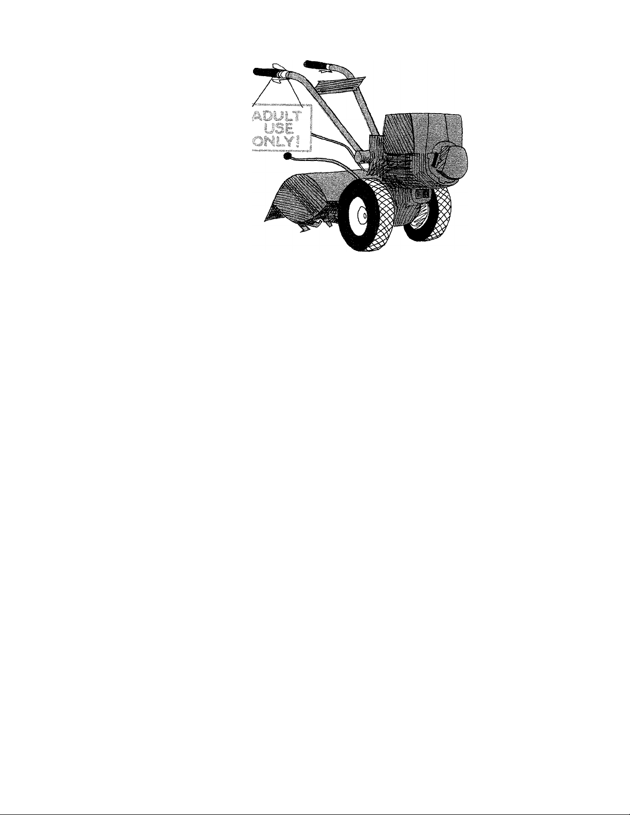
Never allow children or uninstructed adults to
operate tiller.
Shut off engine and disconnect spark plug
wire before unclogging tines or making repairs.
Keep bystanders away from machine.
Keep away from rotating parts.
Section 9: Attachments and Accessories
Index .................................................................
“OPERATOR’S POSITION”
All references to LEFT and
RIGHT sides of the tiller
are given from the opera
tor’s position behind the
handlebars (unless speci
fied otherwise).
72
79
Page 4

Introduction
i-
Welcome to “Power gardening
the TROY-BILT® Tiller way.” Your
new PTO HORSE Model Tiller is a
useful, productive gardening tool
that, with proper care, should last
for many years.
Your tiller was designed to easily
chop up, shred and bury all sorts
of vegetation and organic matter in
the garden in addition to preparing
seedbeds and cultivating. With op
tional tiller attachments it can also
be used for furrowing and hilling,
as well as light earthmoving and
snow removal chores.
The PTO HORSE Model’s design,
with powered wheels ahead of the
separately geared Bolo Tines in
the rear, gives it an outstanding
combination of tilling and com
posting capabilities that allows you
to enrich your soil far beyond your
abilities to do so by hand. This soil
enhancement is gained by tilling in
and burying organic materials such
as leaves, mulches, crop residues,
sod, green manure cover crops
and even standing cornstalks! By
using this method, you will soon
experience better yields in your
garden than ever before. This is
said to be the greatest single
benefit of power gardening “the
different, better, and so much more
enjoyable TROY-BILT® Tiller way.”
We have tried our best to build
your tiller as strong and trouble-
free as we know how. This, of
course, is to our mutual benefit. We
have fewer service problems and
you have a truly reliable machine.
VERY IMPORTANT!
Before trying to operate your tiller or PTO Power Unit
for the first time, please make sure that you:
Complete all of the tiller
assembly steps that are de
scribed in the separate As
sembly Instructions Manual
that came packaged with
this Manual.
Completely familiarize your
self with all of the operating
controls as described in Sec
tion 2 of this Manual.
REMEMBER ... PRACTICE SAFETY AT ALL TIMES!
Read and understand all of
the Safety Instructions in
Section 1 of this Manual.
Read and understand all of
the operating procedures for
the tiller and the PTO Power
Unit, as described in Sections
3, 4 and 5 of this Manual.
Page 5
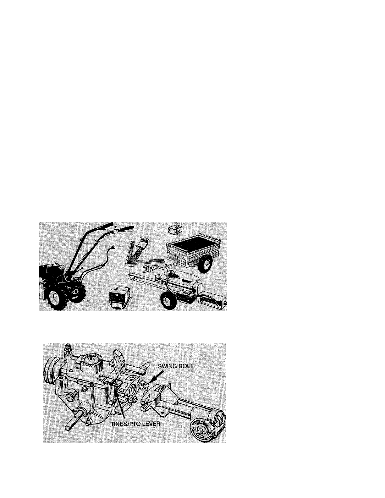
You also have a versatile PTO Power Unit...
In addition to being an incredibiy efficient tiller, your machine can
be quickly converted into a seifcontained PTO (Power Take-Off)
Power Unit that is capable of tow
ing or powering various TROY-BILT
PTO attachments (see Figure 2).
This ability to convert the tiller
into a PTO Power Unit is made
possible by the unique design of
the Horse Modei’s transmission.
As shown in Figure 3, the trans
mission is made up of two sepa
rate cast-iron housings that are
held together by a locking collar, a
dowel pin and two swing-bolts.
Figure 2: The tine attachment can be removed and various powered or nonpowered attachments can be connected to the Power Unit.
Each housing has separate drive
shafts that are joined by a tine
ciutch. This clutch can be engaged
or disengaged by moving the Tines/
PTO Ciutch Lever that is located
on the left side of the PTO Power
Unit transmission.
When the tine attachment is in
place, the lever allows you to
operate the tiller with the tines
disengaged, even when the wheeis
are in motion. This tine disconnect
feature provides added conven
ience when transporting, loading,
or unioading the tiller. When the
lever is in the engaged position.
the tine ciutch connects the two
drive shafts together, transmitting
power to the tines.
If the tine attachment is removed
(by ioosening the two swing-bolts
and sliding the attachment off), the
PTO Power Unit can be used to
tow moderate loads or drag-
behind implements, or to provide
engine power to powered station
ary attachments such as the TROYBILT® Generator, TROY-BILT® PTO
Log Splitter and TROY-BILT® PTO
Chipper/Shredder. This PTO capa
bility truly makes your tiller an allaround, all-season work horse.
For detailed instructions on how
to convert your tilier into a PTO
Power Unit piease refer to Section
5 in this Manual.
A word about
maintenance...
You can help ensure long-lasting
and proper performance from your
PTO HORSE Model by always re
membering to perform the sched
uled maintenance services that are
presented in Section 6 of this
Manual, and in the accompanying
engine manufacturer’s Owner’s
Manual.
By treating your machine with
good care in the manner described
in those pages, your efforts will be
returned many times over in the
form of a more satisfying and
easier operating machine, and
with much more bountiful garden
ing resuits.
Figure 3: The transmission consists of two housings, held together by swingbolts. Separate “dog” clutches on each drive shaft are engaged and disengaged
with the Tines/PTO Clutch Lever.
Page 6

We’re here to serve you!
The whole idea behind TROYBILT® Tiller Factory Service is to
get parts, attachments and service
advice out to you just as quickly
as possible and to answer any
questions you may have about tilling
or gardening, by phone or by letter,
depending upon what is needed.
If you have a question
or problem ...
If you have a question or prob
lem that Is not answered In this
Manual, then please get in touch
with our Technical Service Depart
ment by phone or by letter. One of
our friendly, helpful tiller experts
will gladly help you out.
Nothing is more important to all
of us here at the factory than mak
ing sure that every owner is com
pletely satisfied 1JD0-percent of the
time. You’re always entitled to firstrate service. Please be assured
that we will do our very best to see
that you get it at all times.
Thank you.
Dean Leith, Jr., Sales Manager
For the fastest service, DIAL FREE from:
In the U.S.A..........................................(Toll-Free) 1-800-833-6990
In Canada (Garden Way Canada).... (Toll-Free) 1-800-225-3585
Our business hours are (Eastern Time):
In the U.S.A.: M-F 8 a.m. to 7 p.m.; Sat. 9 a.m. to 4 p.m.
In Canada: M-F 8 a.m. to 5 p.m.
If you need a tiller part...
If you need to order a part for
your tiller, please refer to the sepa
rate Parts Catalog that came with
this Manual. There, you will find
detailed instructions on how to
identify parts and how to place
your order.
Our mailing address Is:
In the U.S.A. In Canada
Troy-Bilt Mfg. Co.
102nd St. & 9th Ave.
Troy, New York 12180
Garden Way Canada
1515 Matheson Blvd. E.
Mississauga, Ontario L4W 2P5
NOTE: When calling or writing, please provide us with your Tiller
Serial Number (See page 5).
If you need engine service or
For engine service or parts, con
tact your nearest engine service
dealer who is authorized to service
the particular make of engine that
is on your tiller. Look in the Yellow
Pages of your telephone directory
under “Engines—Gasoline” for
the name of your nearest service
dealer. The service dealer can
handle all parts, repairs and war
ranty service concerning the en
gine alone.
It is important to remember that
your engine is covered by the en-
parts...
gine manufacturer’s Limited War
ranty and any unauthorized work
done on the engine during the war
ranty period may void your engine
warranty. For full details on the
engine’s Limited Warranty, please
see the separate engine manufac
turer’s Owner’s Manual that came
with this Manual.
If you have any difficulty in find
ing an authorized service dealer
or in obtaining warranty service,
please contact our Technical Serv
ice Department for assistance.
Page 7
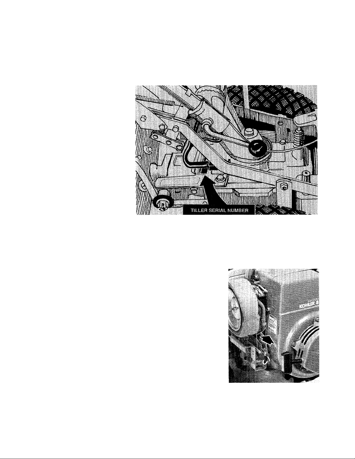
RECORD YOUR TILLER SERIAL NUMBER
To help you as quickly as possi
ble when you write or call for serv
ice or parts, we will need to know
your Tiller Serial Number.
The arrow in the Figure at the
right points to a iocation on the
transmission where the serial
number is located. For ready
reference, please record this
number, aiong with the delivery
date of your tiiier, in the spaces
provided beiow.
Serial Number:
Date of Delivery:
RECORD YOUR ENGINE MODEL NUMBER
Should you ever need engine
service or parts, you may be asked
for the engine model code number.
On the 7HP Briggs & Stratton
engine, the number is stamped on
the top of the blower housing
cover, as shown in Photo 6.
On the 8HP Kohler engine, the
number is located on the right side
of the blower housing cover, be
hind the air cleaner cover (remove
wing nut to remove air cleaner
cover). See Photo 7.
Engine Code:
________________
PHOTO 6: Code number location on
7HP Briggs & Stratton engine.
... .
PHOTO 7: Code number location on
8HP Kohler engine.
Page 8

SECTION 1:
The PTO HORSE Model Tiller
has been designed with many
safety features to help protect indi
viduals from harm and property
from being damaged. However, as
with any type of power equipment,
it is necessary for you and any
TRAINING
1. Read both this Owner/Operator
Manual and the separate engine
Owner’s Manual carefully. Be
thoroughly familiar with the con
trols and the proper use of the
tiller and its engine. Know how to
stop the unit and disengage the
controls quickly.
2. Read the Owner/Operator Man
operator to follow safe operating
practices at all times. Failure to do
so can result in personal injury or
damage to equipment or property.
Before operating or servicing the
tiller or the PTO Power Unit, care
fully read and follow all of the
A
SAFETY ALERT SYMBOL
This symbol is used to alert you to
important safety messages in this
Manual and on your tiller. When
you see this symbol, carefully read
and follow its safety message.
uals provided with any optional
accessories or attachments before
operating. The manuals provide a
detailed description of proper use
Safety Instructions found in this
Owner/Operator Manual and in the
separate Owner’s Manual provided
by the engine manufacturer. If you
have any questions, please call or
write us.
and operation, and point out other
important Safety Instructions.
3. Never allow children to operate
the tiller. Never allow adults to
operate the tiller without proper
instruction.
4. Keep the area of operation clear
of all persons (particularly small
children), and pets.
PREPARATION
1. Thoroughly inspect the area
where the tiller is to be used and
remove all foreign objects before
tilling.
2. Put the Wheels/Tines/PTO Drive
Lever in “NEUTRAL” before starting
the engine.
3. Do not operate the tiller without
wearing suitable outer garments.
Avoid loose garments or jewelry
that could get caught in moving
parts of the tiller or its engine.
4. Do not operate the tiller when
barefoot or wearing sandals,
sneakers, or similar lightweight
footwear. Wear footwear which will
improve footing on slippery sur
faces.
5. Do not till near underground
electric cables, telephone lines,
pipes, or hoses. If in doubt, contact
your telephone or utility company
to locate underground services.
6. Handle fuel with care; it is highly
flammable and its vapors are
explosive.
(a) Use an approved fuel con
tainer.
(b) Never remove gas cap or add
fuel to a running engine or to a
hot engine. Engine shall be al
lowed to cool before refueling.
(c) Keep matches, cigarettes,
cigars, pipes, open flames, or
sparks away from the fuel tank
and fuel container.
(d) Fill fuel tank outdoors with
extreme care. Never fill fuel
tank indoors. Use a funnel or
spout to prevent spilling.
(e) Replace fuel cap securely and
clean up spilled fuel before
restarting.
7. Never attempt to make any ad
justments while the engine is
running or the spark plug wire is
connected, except where specifi
cally instructed to do so.
Page 9
OPERATION
1. Do not put hands or feet near or
under rotating parts.
2. Exercise extreme caution when
operating on or crossing gravel
drives, walks, or roads. Stay alert
for hidden hazards or traffic.
3. After striking a foreign object,
stop the engine, remove the key on
electric start models, disconnect
the spark plug wire, and thoroughiy
i nspect the ti I ier for any damage.
Repair the damage before restart
ing and operating the tiller.
4. Exercise caution to avoid slip
ping or falling.
5. If the machine should start to
vibrate abnormally, stop the engine,
remove the wire from the spark
plug, and check immediately for
the cause. Vibration is generally a
warning of trouble.
6. Stop the engine, remove the key
on electric start models, and dis
connect the spark plug whenever
you leave the operating position,
before unclogging the tines, and
when making any repairs, adjust
ments, or inspections.
7. Take all possible precautions
when leaving the tiller unattended.
Shift into “NEUTRAL”, stop the en
gine, remove the key on electric
start models, and disconnect the
spark plug wire to prevent acci
dental starting.
8. Before cleaning, repairing, or in
specting, stop the engine, remove
the key on electric start models,
and make certain all moving parts
have stopped. Disconnect the
spark plug wire and keep the wire
away from the plug to prevent ac
cidental starting. For electrical
saftey, always remove the cable
from the negative (-) side of the
battery (on electric start models)
before attempting any repairs or
maintenance.
9. Always keep the flap on the tine
hood down when operating the
tiller, except when using the hiller/
furrower attachment.
10. Never operate the tiller without
proper guards, shields, plates, or
other safety protective devices in
place.
11. Do not run the engine in an en
closed area; exhaust fumes con
tain carbon monoxide gas, a deadly
poison that is odorless, colorless
and tasteless. Always make sure
there is adequate ventilation when
the engine is running.
12. Keep children and pets away.
13. Never operate the tiller under
engine power if the Wheel Speed
Lever is in the “FREEWHEEL”
position. In “FREEWHEEL”, the
wheels will not hold the tiller back
and the revolving tines could pro
pel the tiller rapidly, possibly caus
ing loss of control. Always engage
the Wheel Speed Lever in either
the “FAST” or “SLOW” wheel
speed position before starting the
engine or engaging the tines with
the Wheeis/Tines/PTO Drive Lever.
14. Be aware that the tiller may
unexpectedly bounce upward or
jump forward and be propelled
away from you if the tines should
strike or catch extremely hardpacked soil, sod, frozen ground, or
buried obstacles such as large
stones, roots, or stumps. If you are
in doubt about the tiling condi
tions, always use the following
operating precautions to assist you
in maintaining control of the tiller.
(a) Walk behind and to one side of
the tiller, using just one hand
on the handlebars. Relax your
arm, but use a secure hand grip.
(b) Use shallower depth regulator
SAFETY INSTRUCTIONS
settings, gradually working
down deeper with each tilling
pass.
(c) Use slowerwheel, tine and en
gine throttle speeds.
(d) Clearthetillingareaof all
large stones, roots, and other
debris.
(e) Avoid applying downward
pressure on the handlebars. If
necessary, apply slight upward
pressure to prevent the tines
from digging too deeply.
(f) Always avoid contacting hard-
packed soil or sod at the end
of a row by reducing the en
gine speed and lifting the han
dlebars to raise the tines out of
the soii.
(g) In an emergency, stop the tines
and wheels by shifting the
Wheels/Tines/PTO Drive Lever
into “NEUTRAL”. If you cannot
reach the lever or have lost
control of the tiller, LET GO of
the handlebars and all controls
and do not attempt to restrain
the tiller.
15. Do not overload the machine
capacity by attempting to till too
deeply at too fast a rate.
16. Never operate the tiller at high
transport speeds on slippery sur
faces.
17. Do not operate til Ier on a slope
that is too steep for safety. When
on slopes, slow down and make
sure you have good footing. Never
permit the tiller to free-wheel down
slopes.
18. Clear the area of bystanders
before tilling.
Page 10

19. Use only attachments and
accessories that are approved
by Garden Way Manufacturing
Company.
20. Use tiller attachments and
accessories when recommended.
21. Never operate the tilier without
good visibility or light.
22. Never operate the tilier when
fatigued, or whiie under the in
fluence of alcohol, drugs, or
medication.
23. Do not change the engine
governor settings or overspeed
the engine.
24. Do not touch engine parts that
may be hot from operation. Allow
parts to cool before inspecting,
cleaning, or repairing.
25. POISON/DANGER-CAUSES
SEVERE BURNS. The battery on
electric start models contains
sulfuric acid. Avoid contact with
skin, eyes or clothing. Antidote:
EXTERNAL—Flush immediately with
lots of water.
INTERNAL—Drink large quantities
of water or milk. Follow with milk of
magnesia, beaten eggs or vegetable
oil. Call physician immediately.
EYES—Flush with water for 15 min
utes and get prompt medical atten
tion. Keep out of reach of children.
26. DANGER-BATTERIES PRO
DUCE EXPLOSIVE GASES. Keep
sparks, flame, or smoking materi
als away. Ventilate when charging
or using in an enclosed space.
Always shield eyes when working
near batteries.
27. Please Remember: You can al
ways stop the tines and wheels by
putting the Wheels/Tines/PTO Drive
Lever in “NEUTRAL”, or by moving
the Throttle Lever to the “STOP”
position. If you have lost control of
the tiller, and cannot reach the
levers, LET GO of the handlebars
and all controls and do not attempt
to restrain the tiller. The Forward
Interlock Safety System will stop
the engine.
28. Look behind and use care
when backing. For added safety,
put Wheel Speed Lever in “SLOW”
before reversing.
29. When loading or unloading
unit, always disengage the tines
and use slower wheel and engine
throttle speeds. Use sturdy ramps
that are wide and strong enough
to support both the tiller and oper
ator (tiller weighs between 280 and
325 lbs.). Never go down ramps in
“FORWARD” drive as the tiller
could tip forward, exposing you to
the tines (which should be disen
gaged). Always use “REVERSE”
drive and back down ramps. To go
up ramps, use “FORWARD” drive
and follow tiller up ramps.
30. The Forward Interlock Safety
System should first be tested for
proper functioning every time the
tiller or PTO Power Unit is used.
See Section 3 in this Manual for
the testing procedure to follow.
31. When snowplowing with the
optional dozer blade, either remove
the tines completely, or disengage
the tines with the Tines/PTO Clutch
Lever. Revolving tines could be
dangerous on slippery sidewalks
or driveways.
MAINTENANCE AND STORAGE
1. Never perform any maintenance
while the engine is running or the
spark plug wire is connected, ex
cept where specifically instructed
to do so.
2. Keep machine, attachments
and accessories in safe working
condition.
3. Check all nuts, bolts, and screws
at frequent intervals for proper tight
ness and to be sure the equipment
is in safe working condition.
4. Never store the machine with
fuel in the fuel tank inside a build
ing where fumes may reach an
open flame or spark, or where igni
tion sources are present (such as
hot water and space heaters, fur
naces, clothes dryers, stoves, elec
tric motors, etc.).
5. Allow the engine to cool before
storing in any enclosure.
6. To reduce fire hazard, keep the
engine free of grass, leaves or ex
cessive grease.
7. Store gasoline in a cool, wellventilated area, safely away from
any spark or flame-producing
equipment. Store gasoline in an
approved container, safely out of
the reach of children.
8. Refer to the Maintenance and
Service Section of this Manual if
the tiller is to be stored for an
extended period.
8
DECALS
Safety decals and operating in
struction decals are located on the
handlebars, the operator control
panel, the tine hood, the engine,
and the transmission. Contact us
immediately for replacement decals
if any are missing, illegible, or
damaged. See your Parts Catalog
for the exact location and part
number of each decal. Do not at
tempt to operate machine if any
decals are illegible or missing.
Page 11
SECTION 2:
Before using your tiller or PTO
Power Unit for the first time, be
come thoroughly familiar with the
operation of the controls by mov
ing them to their various positions
Tiller and PTO Power Unit Controls
1. Wheels/Tines/ PTO Drive Lever
This lever engages power from
the engine to the transmission
(see Photos 2-1, 2-2, and 2-3).
There are three positions of this
lever: "FORWARD”, “NEUTRAL”
and “REVERSE”.
When you move the lever down
to the “FORWARD” position, it
raises the engine upward and tight
ens the drive belt located between
the engine pulley and the transmis
sion pulley. The transmission then
while the engine is not running.
Taking the time now to fully under
stand the location, function, and
operation of these controls will
greatly add to the productive use,
drives the wheels and tines in a
forward direction. (If the tines are
removed and replaced with a PTO
driven attachment, the lever will
apply power to the attachment.)
The lever will remain in “FOR
WARD” until you tap or lift it
upward and let it go.
When you move the lever all the
way up to the “REVERSE” position,
it lowers the engine and causes
the drive belt to go slack. At the
same time, the rubber reverse disc
on the engine pulley comes into
contact with the transmission pul
ley, causing the transmission to
rotate the wheels and tines (or any
PTO driven attachment) in a re
verse direction. The reverse oper
ation will continue as long as you
hold the lever up. When you re
lease the lever, it will automatically
return to “NEUTRAL”. This is a
safety feature for your protection.
When the lever is in “NEUTRAL”,
the engine will continue to run, but
power will not be transferred to the
transmission.
safe operation, and full enjoyment
of your new machine. The proper
operation of each control is dis
cussed in detail in this Section.
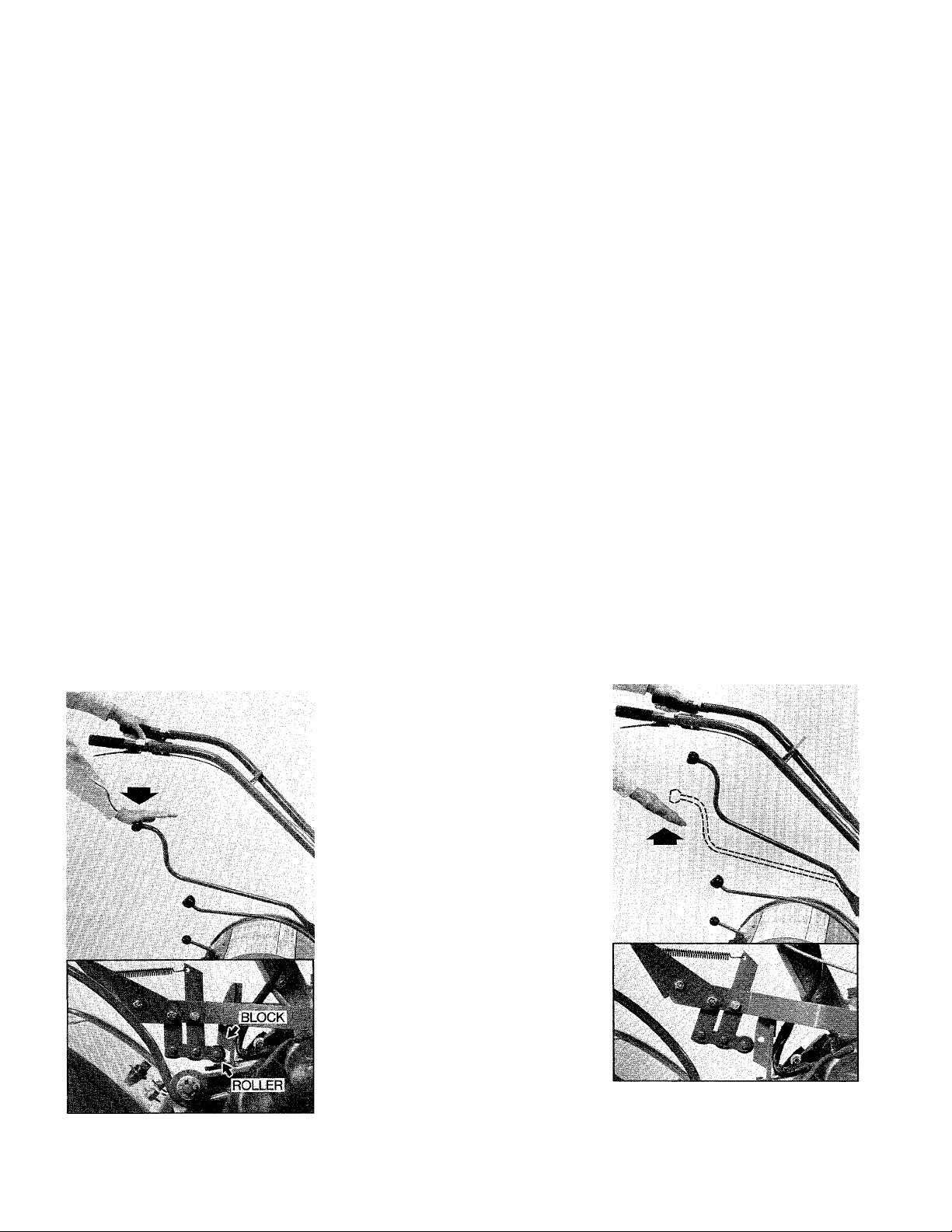
To operate the Wheels/Tines/
PTO Drive Lever:
A. Practice shifting the lever as
described next. As you do, note in
the accompanying photos the vari
ous positions that the clutch roller
takes on the belt adjustment block.
Your roller should be similarly po
sitioned when you shift the lever.
B. For forward motion of the wheels
and tines (or to apply power to any
PTO driven attachment), push the
iever all the way down and release
it. See Photo 2-1. To return to
“NEUTRAL”, tap or lift the lever up
and let it go (Photo 2-2).
2-1: Push lever down for “FORWARD”.
The clutch roller (lower photo) will be
engaged below the adjustment block.
IMPORTANT
Moving the lever to the “NEUTRAL”
position will stop all wheel and tine
motion, or power to any PTO driven
attachment.
2-2: Tap or lift lever up to return to
“NEUTRAL”. The clutch roller (lower
photo) will rest anywhere on the face
of the adjustment block, depending
upon drive belt length and tension.
Page 12
C. Before shifting into “REVERSE”,
always look behind you to make
sure there are no obstacles in the
way. Then raise the tines out of the
soil by lifting up on the handlebars,
and slowly lift the lever all the
way up. See Photo 2-3. To return
to “NEUTRAL”, simply let go of
the lever.
Please remember that you should
never till when in “REVERSE” (al
ways disengage the tines with the
separate Tines/PTO Clutch Lever
before reversing). You should also
avoid using “REVERSE” with any
PTO driven attachments as they are
not designed for reverse operation.
Until you are completely com
fortable with handling the machine
when it is moving backward, it is a
good idea to use “REVERSE” only
at slower wheel and engine throttle
speeds. Many people never shift
into “REVERSE” when the separate
Wheel Speed Lever is in the “FAST”
wheel speed position. This is a
good rule to follow.
2-3: Lift handlebars, then lift and hold
lever up to go in reverse. Let go of
lever to stop reverse motion. (Note
that the clutch roller doesn’t move very
far from “NEUTRAL” to “REVERSE”.)
A CAUTION
TO AVOID PERSONAL INJURY OR
DAMAGE TO EQUIPMENT:
• Always place the Wheeis/Tines/
PTO Drive Lever in “NEUTRAL” be
fore starting the engine, and before
engaging the wheels, tines or other
PTO driven attachments.
• Always make sure there are no
obstacles behind you before oper
ating in “REVERSE”.
• The Wheels/Tines/PTO Drive
Lever should automatically return
to “NEUTRAL” when you release it
from the “REVERSE” position. If it
fails to do so, push it down into
“NEUTRAL”. Then, immediately re
fer to Section 6 of this Manual
for adjustment instructions.
• There should not be any reverse
motion if the Wheels/Tines/PTO
Drive Lever is not held in the “RE
VERSE” position. If there is, the
machine is badly out of adjustment
and it should not be operated until
the condition is corrected. See Sec
tion 6 for adjustment instructions.
• Always return to “NEUTRAL”
and allow all motion to stop before
shifting into “FORWARD” or “RE
VERSE”. This pause between shift
ing will protect the drive belt,
reverse disc, and other transmis
sion components from undue wear
and damage.
2. Forward Interlock Levers
There are two Forward Interlock
Levers, one located directly below
each handlebar grip. See Photo
2-4. One or both of the interlock
levers must be kept squeezed
against the handlebar grip(s) when
ever the Wheels/Tines/PTO Drive
Lever is engaged in “FORWARD”.
If you release both interlock
levers before first returning the
Wheels/Tines/PTO Drive Lever to
“NEUTRAL”, the engine will shut
off. This is a safety feature for your
protection should you ever lose
control of the machine and cannot
stop forward motion by moving the
Wheels/Tines/PTO Drive Lever into
“NEUTRAL”.
NOTE: The interlock levers do
not affect operation when the
Wheels/Tines/PTO Drive Lever is
in “REVERSE”.
To operate the
Forward interlock Levers:
A. Squeeze one of the interlock
levers against the handlebar grip
before engaging the Wheeis/Tines/
PTO Drive Lever in “FORWARD”.
Continue to squeeze one or both
of the interlock levers during all
forward operation.
B. To stop forward operation in
normal use, first shift the Wheels/
Tines/PTO Drive Lever into “NEU
TRAL” and then release BOTH in
terlock levers. All forward motion
will stop, but the engine will con
tinue to run.
C. To stop forward motion in an
emergency, release BOTH interlock
levers. This will cause the engine
to shut off, stopping all forward
motion.
10
2-4: The Forward Interlock Levers.
A WARNING
To help avoid personal injury, the
Forward Interlock Safety System
should first be tested for proper
functioning every time the tiller or
PTO Power Unit is used. See Sec
tion 3 in this Manual for the easy
testing procedure to follow.
Page 13
CONTROLS mo FUUCTIONS
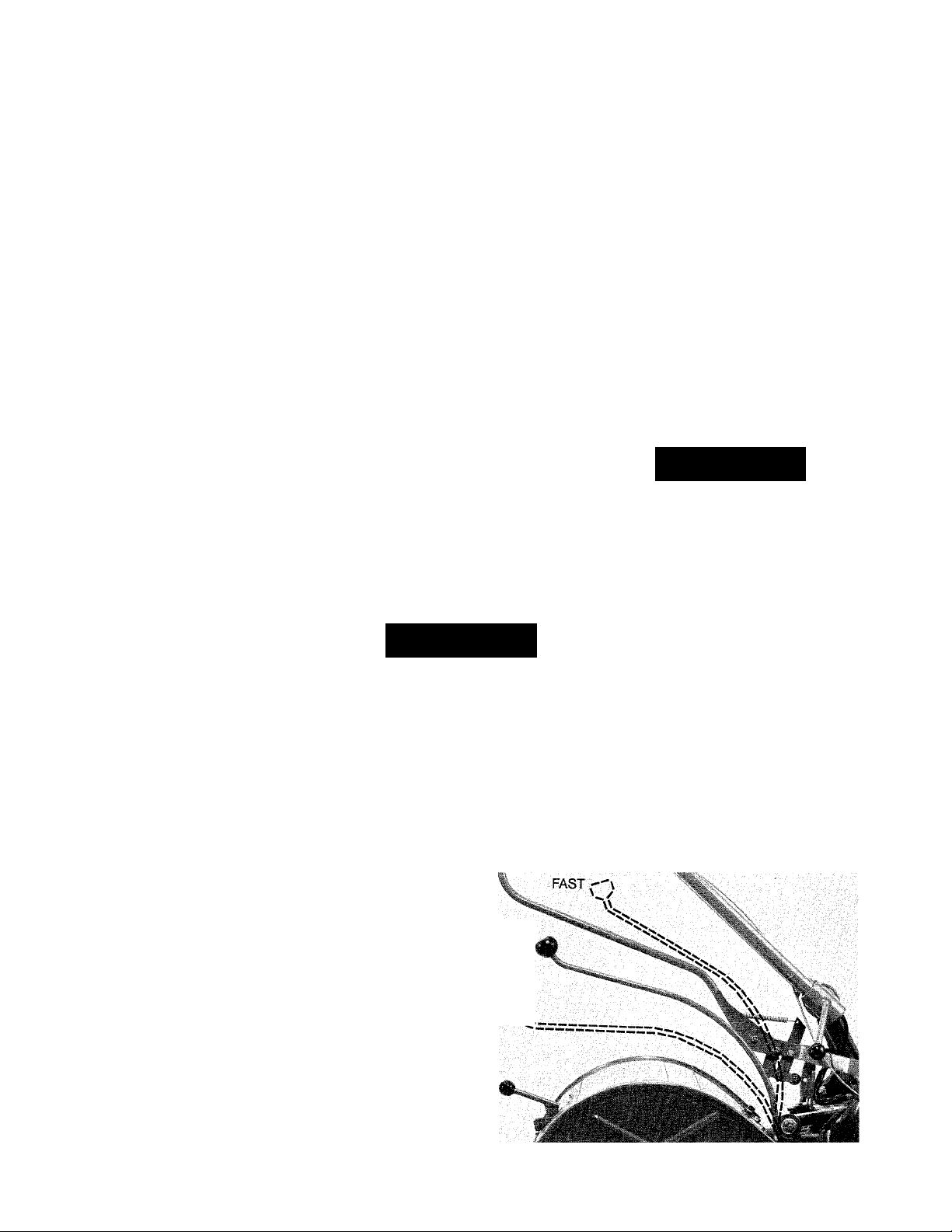
3. Wheel Speed Lever
This lever allows you to choose
between two different wheel
ground speeds: “SLOW” or
“FAST”. It also has a “FREE
WHEEL” position, in which the
wheels are free to turn without the
engine running. See Photo 2-5.
When the lever is engaged in
either “SLOW” or “FAST” and the
Wheels/Tines/PTO Drive Lever
is in either “FORWARD” or
“REVERSE”, the wheels will turn
under engine power.
When the lever is in the “FREE
WHEEL” position and the Wheels/
Tines/PTO Drive Lever is in “NEU
TRAL”, the machine can be moved
(on level ground) by pushing or
pulling on the handlebars. The
“FREE WHEEL” position is also
used when you are operating a
PTO driven stationary attachment,
in which case you would not want
the wheels to move when the
Wheels/Tines/PTO Drive Lever is
engaged in “FORWARD”.
IMPORTANT
By moving the forward drive belt
(see “Changing Belt Speeds” in
Section 3) into one of two different
belt ranges, you can obtain a total
of fod-' different forward wheel
ground speeds. There are, however,
only two reverse wheel ground
speeds (“SLOW” or "FAST”), be
cause the rubber reverse disc, not
the drive belt, drives the wheels in
the reverse direction.
the selected wheel gear. When the
clutch goes into gear, you will no
longer be able to roll the wheels.
When you shift the lever into
“FREE WHEEL”, the sliding clutch
is disengaged from both wheel
gears and the wheels will roll freely.
Note that there should not be any
“clicking” noise when you’re in
“FREE WHEEL”. If there is, shift the
lever a little more (either up or
down) to eliminate the noise—and
the rubbing of the clutch and gear
that causes it.
To operate the Wheel Speed
Lever:
A. With the Wheels/Tines/PTO
Drive Lever in “NEUTRAL”, roll the
wheels a few inches in either di
rection while you push the Wheel
A WARNING
Never put revolving tines in the soil
when the Wheel Speed Lever is in
“FREE WHEEL”. Doing so can
cause the tiller to be propelled rap
idly by the tines, possibly causing
loss of control and serious per
sonal injury. Always engage the
Wheel Speed Lever in either
“SLOW” or “FAST” wheel speed
before putting the tines in the soil.
FREE WHEEL
Speed Lever down to the “SLOW”
position, or up to the “FAST” posi
tion. See Photo 2-5. When the lever
is in gear, you will no longer be
able to roll the wheels.
B. With the Wheels/Tines/PTO
Drive Lever in “NEUTRAL”, move
the Wheel Speed Lever in between
the “SLOW” and “FAST” wheel
speed positions to place the wheels
in “FREE WHEEL”.
A CAUTION
TO AVOID PERSONAL INJURY OR
DAMAGE TO EQUIPMENT:
• Use the “SLOW” wheel speed
position when first learning to op
erate the machine and whenever
you operate in “REVERSE”.
• Do not shift the Wheel Speed
Lever when heading up or down a
slope. If the lever is accidentally
placed in “FREE WHEEL”, the ma
chine could roll out of control.
• Place the Wheels/Tines/PTO
Drive Lever in “NEUTRAL” before
shifting into “SLOW” or “FAST”.
This will prevent damage to the
clutch or wheel speed gears.
• Do not attempt to stop the
wheels by shifting the Wheel Speed
Lever. Always put the Wheels/
Tines/PTO Drive Lever in “NEU
TRAL” to stop the wheels.
When you shift the lever into
“SLOW” or “FAST”, it moves a slid
ing clutch inside the transmission
to the left or right to engage the
slow speed wheel gear or the fast
speed wheel gear. When engag
ing the clutch, you should roll the
wheels forward or backward a few
inches to help align the clutch with
SLOW /s
2-5: The Wheel Speed Lever.
11
Page 14

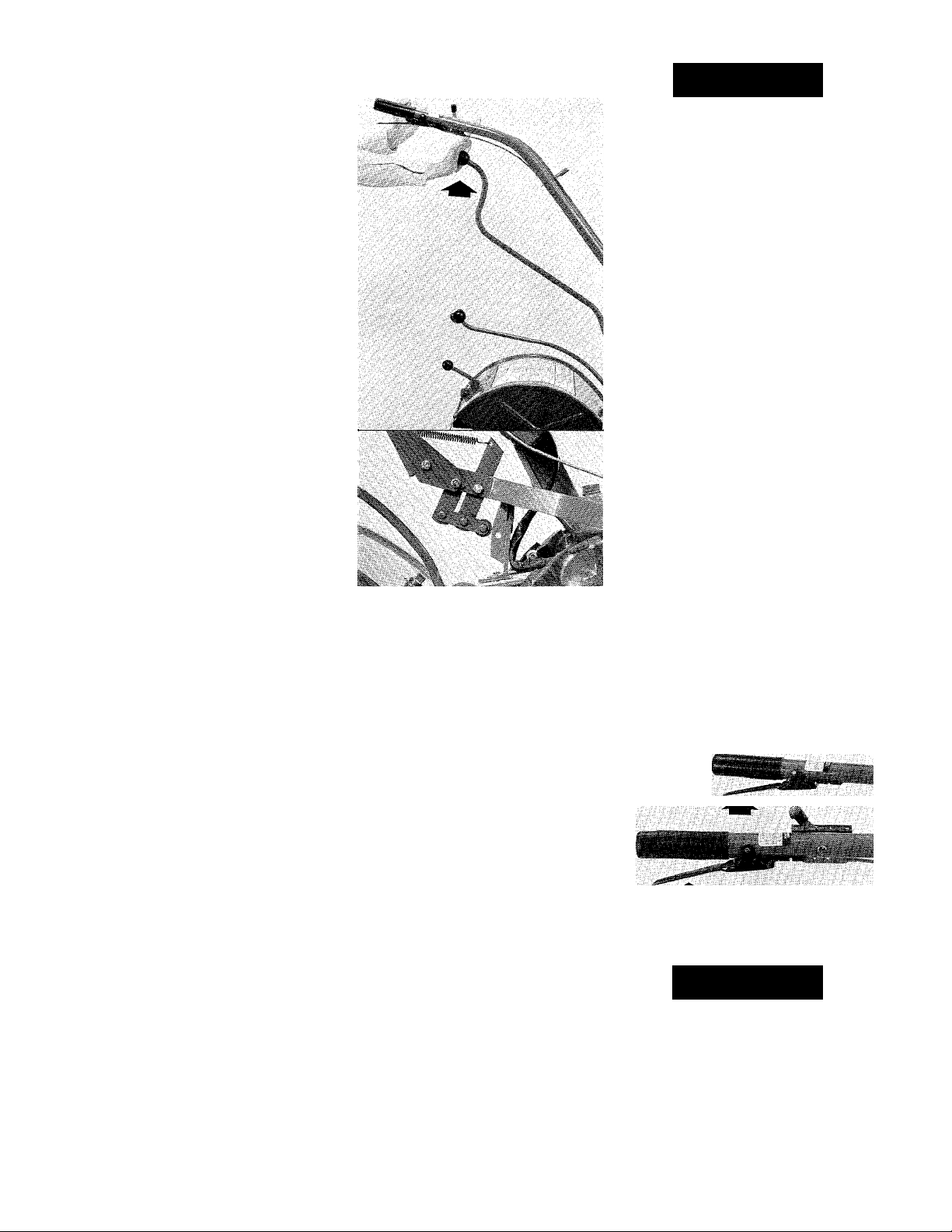
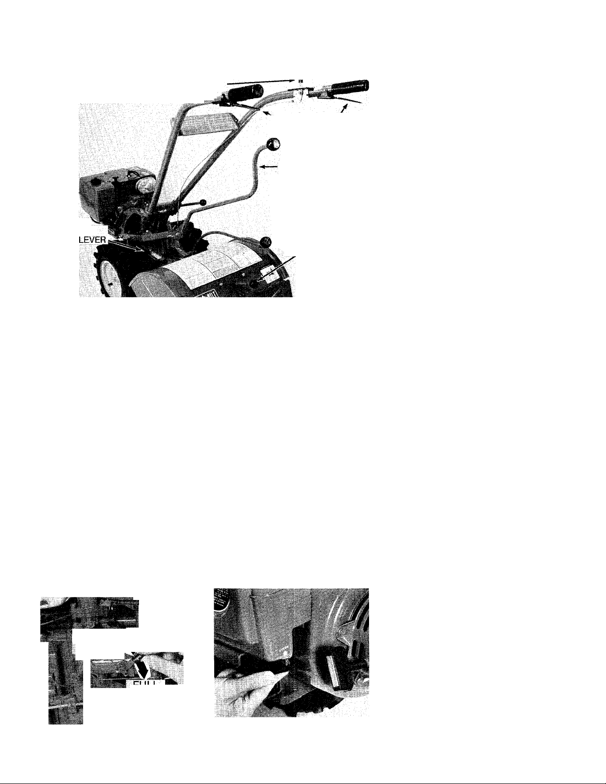
4. Tines/PTO Clutch Lever
5. Depth Regulator Lever
This lever is located on the
left side of the transmission, just
forward of the tiller tine hood.
There are two operating positions:
“ENGAGE” and “DISENGAGE”.
See Photo 2-6.
When you move the lever to the
“ENGAGE” position, it moves the
“dog” clutch on the PTO Power ^
Unit drive shaft backward until it
engages the “dog” clutch on the
tine attachment drive shaft. (If the
tines are removed and replaced
with a PTO driven attachment, the
“dog” clutch on the power unit will
engage with the “dog” clutch on
the PTO driven attachment). Engine
power will then be applied to the
tines or PTO driven attachment
when the separate Wheels/Tines/
PTO Drive Lever is engaged in
“FORWARD” or “REVERSE”.
In the “DISENGAGE” position, the
“dog” clutches are disengaged,
and power will not be applied to
the tines or PTO attachment.
When operating the tiller, the
“DISENGAGE” position allows you
to stop the tines while the sep
arately controlled wheels continue
to rotate. You should use this fea
ture whenever you are transport
ing, loading or unloading, turning
around, or backing the tiller up.
You should also disengage the
lever before towing or transporting
any attachment.
When the tines are removed and
a PTO driven attachment that oper
ates from a stationary position is
installed, the “ENGAGE” position
allows you to power the attachment
while the wheels on the PTO Power
Unit are not moving.
Always place the Wheels/Tines/
PTO Drive Lever in “NEUTRAL” be
fore shifting the Tines/PTO Clutch
Lever. Doing so will help prevent
damage to the transmission that
could occur if you try to engage or
disengage the separate drive shaft
clutches while they are turning
under power.
To operate the Tines/PTO Clutch
Lever:
A. Put the Wheels/Tines/PTO Drive
Lever in “NEUTRAL”.
B. Pull the Tines/PTO Clutch Lever
out and then slide it into the “EN
GAGE” or the “DISENGAGE” slot.
C. After selecting the “ENGAGE”
position, do not immediately shift
the Wheels/Tines/PTO Drive Lever
into “REVERSE”. Always use “FOR
WARD” first, to help align the drive
shaft clutches inside the transmis
sion. NOTE: The lever should move
easily. If it doesn’t, then the “dog”
clutch inside the PTO Power Unit
transmission may need to be lubri
cated. See “Tiller Lubrication” in
Section 6 of this Manual.
A CAUTION
TO AVOID PERSONAL INJURY OR
DAMAGE TO EQUIPMENT:
• Always disengage the Tines/
PTO Clutch Lever before reversing,
transporting, turning around, or
loading or unloading the tiller or
PTO Power Unit.
• Do not attempt to stop the tines
or any PTO driven attachment by
disengaging the Tines/PTO Clutch
Lever. Always put the Wheels/
Tines/PTO Drive Lever in "NEU
TRAL” to stop all motion.
• Read the Owner/Operator Man
ual provided with any attachment
before attempting to operate the
attachment.
2-6: The Tines/PTO Clutch Lever.
This lever is located at the rear
of the tine hood—see Photo 2-7. It
is used to regulate the tilling depth
of the tines.
To operate the lever, pull it straight
back and then slide it up or down
to any of eight different notched
settings.
When the lever is moved all the
way down until it engages the high
est notch in the lever, it places the
tines in the “TRAVEL” position. In
this position the tines will clear the
ground by approximately 2-inches,
allowing you to transport the tiller
without the tines—which should be
disengaged—scraping your lawn
or driveway.
For shallow tilling and cultivat
ing, you should place the lever in
the second or third notch from the
top. These positions will allow the
tines to dig just a few inches into
the soil. The remaining notches
are used for deeper tilling (up to
8-inches deep, depending on the
soil conditions), and for turning
under organic matter.
Further details regarding the
proper use of this lever will be
found in Section 4 of this Manual
(see “Tilling Depths”).
A WARNING
To help avoid personal injury,
always place the tines in the
“TRAVEL” position before starting
the engine. This prevents the tines
from touching the ground until you
are ready to begin tilling.
2-7: The Depth Regulator Lever.
I
12
Page 15

FüMCTiOMS
6. Handlebar Height
Adjustment Lever
This lever is located near the
bottom of the handlebars, on the
right side of the tiller. See Photo
2-8. It allows you to adjust the han
dlebars up or down to any of four
different settings.
As a general rule, the handlebars
should be adjusted to approxi
mately waist level when the tines
are 3 to 4-inches in the soil, but
you should try different settings to
find the one that is most comforta
ble for you.
» s
N
1
2-8: Handlebar Height Adjustment
Lever.
To operate the Height Adjustment
Lever:
A. Stop the engine before adjust
ing the handlebars.
B. Support the handlebars with
one hand while unwinding the lever
enough so that the teeth in the
ratchets are disengaged.
C. Move the handlebars up or
down to either of two preset height
adjustment settings and then re
tighten the lever securely.
D. Two additional height settings
can be obtained by switching the
inside handlebar ratchets, as
shown in Figure 2-9. This will
change the handlebar height a few
inches higher or lower than the
lowest setting obtained in Step C.
2-9: Switch ratchets to obtain two
more height settings.
A WARNING
For use with the PTO Chipper/
Shredder Attachment only, the
handlebars can be swung 30° to
the right side by loosening the
mounting bolt at the bottom of the
handlebar base. NEVER OPERATE
THE TILLER OR OTHER ATTACH
MENTS WITH THE HANDLEBARS
SWUNG OUT TO THE RIGHT SIDE.
Doing so could result in unsafe
handling and personal injury.
ENGINE CONTROLS
The following are descriptions of
the controls on your 7 HP Briggs &
Stratton Engine or 8 HP Kohler
Engine. Additional information on
the safe, efficient operation of your
engine is given in the engine man
ufacturer’s Owner’s Manual which
was included in your literature
package. Please read that literature
carefully and save it for future
reference.
A WARNING
To avoid personal injury or dam
age to equipment, do not attempt
to start your engine at this time.
Complete starting instructions for
the engine are given in Section 3,
“Operation of Tiller.”
1. Engine Throttle Lever
This lever is located on the right
side handlebar (see Photo 2-10). It
is used to regulate engine speeds
as well as to start and stop the
engine.
In general, faster engine speeds
will be required when breaking new
ground or tilling under heavy crop
residues, but remember to use
only as fast an engine speed as is
needed to do the job. Try to judge
when the engine is providing the
proper amount of power—not too
little, but not too much. The sound
of the engine running will be your
best guide.
IMPORTANT
Factory settings of the throttle cable
should be satisfactory for most con
ditions. If adjustments are needed,
refer to Section 6 of this Manual.
To operate the Engine Throttle Lever:
A. When starting the engine, first
make certain that the Wheels/
Tines/PTO Drive Lever is in “NEU
TRAL”. Then, place the lever ap
proximately halfway between the
“SLOW” and “FAST” throttle set
tings. This position should provide
the carburetor with sufficient gas
oline flow to start the engine. How
ever, you may need to experiment
the first few times to find that “just
right” starting position.
B. For faster engine speeds move
the lever forward toward the
“FAST” setting; for slower speeds
......
.
2-10: The Engine Throttle Lever.
move it backward toward the
“SLOW” setting.
C. To stop the engine, move the
lever all the way back to the
“STOP” position (during normal
operation you would first place the
Wheels/Tines/PTO Drive Lever in
“NEUTRAL” and then release both
Forward Interlock Levers before
stopping the engine).
13
Page 16

2. Engine Choke Control
Your erigine is equipped with a
manually operated choke control
as shown in Photo 2-11 or 2-12.
The choke makes starting a cold
engine easier by decreasing the
amount of air in the carburetor’s
air-fuel ratio, thus creating a richer
fuel mixture. The use of the choke
for starting will vary, depending on
air temperature and altitude.
To operate the Choke Control:
A. Before starting a cold engine,
set the choke in the “FULL CHOKE”
position. On the 7 HP Briggs &
Stratton Engine, move the lever all
the way down. On the 8 HP Kohler
Engine, move the lever all the
way up.
B. When the engine starts, slowly
move the lever to the “CHOKE
OFF” position (all the way up for
the 7 HP Briggs & Stratton Engine;
all the way down for the 8 HP
Kohler Engine).
C. If the engine should falter with
the choke at “CHOKE OFF”, return
the lever to a position halfway be
tween “FULL CHOKE” and “CHOKE
OFF”. As soon as the engine runs
smoothly, return the lever to
“CHOKE OFF”.
D. When restarting an already
warm engine, you may not have to
use the choke at all. However, if
the engine falters or hesitates, try
using a “HALF CHOKE” position
until it runs smoothly, and then
return the lever to “CHOKE OFF”.
A CAUTION
Never operate the engine under a
load (tines, wheels, or PTO attach
ments engaged) without first return
ing the choke control to “CHOKE
OFF”. Failure to do so can quickly
build up carbon deposits that can
harm the engine.
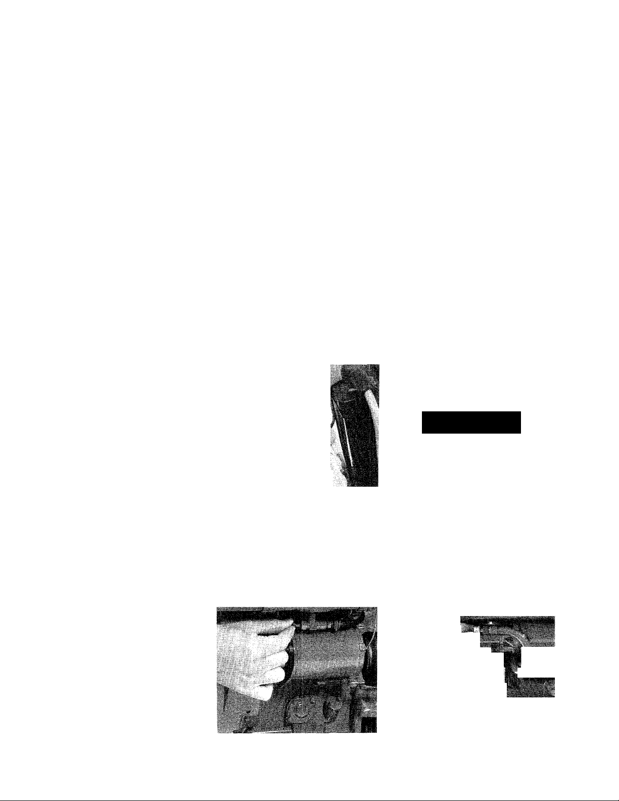
3. Engine Recoil Starter
The recoil starter is located at
the front of the engine, as shown
in Photo 2-13 or 2-14. It is used to
start engines that are not equipped
with the optional key switch start
ing feature.
To operate the Engine Recoil
Starter:
A. When starting the engine, first
make certain that the Wheels/
Tines/PTO Drive Lever is in
“NEUTRAL”.
B. Place your free hand in the lo
cation shown in Photo 2-13 or 2-14
to help stabilize the machine.
C. Grasp the starter rope handle
with your other hand and pull the
CHOKE
OFF
H'
FULL
CHOKL-
2-11 : Choke control on 7 HP Engine. 2-12: Choke control on 8 HP Engine.
* '-A ■
?
FULL CHOKE
L -'
.if-
%
2-13: Starting the 7 HP Briggs &
Stratton Engine.
2-14: Starting the 8 HP Kohler Engine.
handle out slowly until it is harder
to pull because of engine compres
sion. Then pull the handle with a
rapid, continuous, full-arm stroke.
Let the starter rope rewind slowly
after each start attempt.
To help avoid personal injury, be
sure that the area behind you is
clear before pulling the starter rope.
A WARNING
14
Page 17
CONTROLS AND FUNCTIONS
4. Key Switch Starter
The key switch starter for the
optional electric start engine is
located on the right side of the
battery hold-down clamp, as shown
in Photo 2-15. There are three op
erating positions identified on the
switch: “OFF”, “RUN” and “START”.
When the key is turned to the
“START” position, the battery sup
plies an electrical current to the
engine’s starter motor which then
cranks the engine over at a fast
enough speed for starting.
During engine operation, the bat
tery is recharged automatically via
a small recharging current that the
engine sends back to the battery
through the electrical system’s re
charging line.
. If the electrical system should
ever fail to start or stop the engine,
IMPORTANT
If the battery will not be used for
oxlondcd periods of time, it should
be fully charged before placing it
in storage. Before reinstalling the
battery after storage, give it a thor
ough recharge. See “Battery Care
and Maintenance” in Section 6 for
charging instructions.
refer to the “Electric Start Trouble
shooting” instructions found in
Section 6 of this Manual.
To operate the Key Switch Starter:
A. When starting the engine, first
make certain that the Wheels/
Tines/PTO Drive Lever is in “NEU
TRAL”. Also remember to set the
Engine Throttle Lever in the start
ing position and the Choke Control
in the “FULL CHOKE” position (for
cold starts).
B. Insert the key firmly into the key
switch slot and turn it all the way
to the right, to the “START” po
sition. When the engine starts,
release the key and it will auto
matically return to the “RUN” posi
tion. Do not hold the key in the
"START” position for longer than a
‘tti a::.l Lij: ftt,
2-15: The Key Switch Starter.
few seconds. Prolonged cranking
can damage the starter motor if it
is cranked more than 15 seconds
per minute.
C. There are two ways to stop the
engine:
(1) Put the Wheels/Tines/PTO
Drive Lever in “NEUTRAL”, re
lease both Forward Interlock
Levers, and then pull the throt
tle lever all the way back to the
“STOP” position. Turn the key
to “OFF” and remove the key.
(2) Put the Wheels/Tines/PTO
Drive Lever in “NEUTRAL”, re
lease both Forward Interlock
Levers, and then turn the key
to “OFF”. Put the throttle lever
in the “STOP” position and re
move the key.
NOTE: To stop forward motion in an
emergency, release both Forward
Interlock Levers. This will cause
the engine to shut off.
A WARNING
To avoid injury due to accidental
or unauthorized engine starting,
always remove the key from the
switch when leaving the machine
unattended.
5. Fuel Tank Shut-Off
Valve
Your engine is equipped with a
fuel tank shut-off valve. It is located
underneath the gasoline tank. See
Photo 2-16 or 2-17.
This valve stops the flow of gas
oline from the fuel tank to the car
buretor. Before starting, make sure
that the valve is in its OPEN posi
tion (rotate counterclockwise sev
eral turns) or the engine will quit
from lack of fuel shortly after you
start it.
NOTE: Close fuel shut-off valve
when engine is transported to pre
vent fuel leakage from carburetor.
2-16: Fuel shut-off valve on 7 HP
Briggs & Stratton Engine.
15
, 'pr;, m
2-17: Fuel Shut-off valve on 8 HP
Kohler Engine.
Page 18

SECTION 3:
Before you attempt to operate
your tiller make sure that you’ve
read and fully understand all of the
Safety instructions in Section 1
and the Controls information in
Section 2. You should also read
this Section carefully before start
ing your engine.
You should practice with your
tiller in an open, level area before
you use it in your garden. While
practicing, do so without the tines
revolving (disengage the tines with
the Tines/PTO Clutch Lever).
When you’ve become completely
familiar with your tiller, you can
begin using it in your garden.
A WARNING
To avoid personal injury or damage
to equipment, read the Owner/Operator Manuals provided with any
optional accessories or attach
ments before operating the tiller or
PTC Power Unit. The Manuals pro
vide a detailed description of proper
use and operation, and point out
other important Safety Instructions.
Break-in operation
During the first few hours of new
machine operation, you must per
form the following maintenance.
For subsequent required mainte
nance, and the procedures to fol
low, please refer to Section 6 in
this Manual.
1. CHANGE ENGINE OIL. The en
gine oil must be changed after the
first 5 hours of new engine opera
tion. Thereafter, change the oil after
each 10 operating hours. Change
the oil more frequently when oper
ating in extremely dusty or dirty
conditions.
2. CHECK TRANSMISSION GEAR
OIL LEVEL. The gear oil levels must
be checked after the first 2 hours
of new tiller operation. Thereafter,
check the oil levels after every 30
operating hours.
■a
3. CHECK DRIVE BELT TENSION.
The tension on the drive belt may
need to be adjusted after the first 2
or 3 hours of new operation due to
initial belt wear and seating of the
belt with its pulleys. Thereafter,
check the tension after every 10
operating hours.
4. CHECK BOLTS AND NUTS.
Check for loose bolts and nuts
after the first 2 hours of new tiller
operation. Thereafter, check after
every 10 operating hours.
Preparation before starting
Make the following checks and
perform the services as required
before starting the engine.
1. CHECK ENGINE OIL LEVEL.
Check the oil level in the engine
crankcase. Do not run the engine
unless the proper oil level is
maintained.
2. SERVICE AIR CLEANER. Make
sure that the air cleaner elements
are not dirty.
3. CHECK SAFETY GUARDS. Make
sure that all safety guards and cov
ers are securely in place.
4. ATTACH SPARK PLUG WIRE. Be
sure that the spark plug wire is
securely attached to the spark
plug.
5. CHECK ENGINE COOLING
SYSTEM. The cooling fins and air
intake screen must be clean to
ensure adequate cooling.
■
1 I
mW
bWÜ
■'.a.', ■
............
.................................
6. ADJUST HANDLEBARS. Set the
handlebars to a comfortable oper
ating height.
7. CHECK BATTERY (Eiectric Start
Models). Make sure that the bat
tery is properly filled and that all
electrical connections are clean
and tight.
8. FiLL FUEL TANK WITH GASO
LINE. Avoid using gasoline that is
not fresh, as stale fuel can cause
gum deposits to form in the carbu
retor and fuel lines. Fuel should
not be stored for more than six
months. The use of unleaded gas
oline is recommended as it resuits
in fewer combustion deposits and
longer engine life. DO NOT MIX OIL
WITH THE GASOLINE.
(a) Clean the fuel cap and its sur
rounding area before removing the
cap.
(b) Use a clean funnel to add fuel
to the fuel tank.
(c) Do not fill the tank to the point of
overflowing. Fill to within Ta-inch of
the top of the tank to prevent spiils
and to allow for fuel expansion.
(d) For 7 HP Briggs & Stratton
Engines: use clean, fresh, lead-free
automotive gasoline (leaded gas
oline may be used if unleaded is
unavailable). Use gasoline that has
a minimum octane rating of 77. Do
not use gasoline containing Meth
anol. The use of gasoline which
contains alcohol (such as gasohol)
is not recommended. If you are
....
16
Page 19
using gasohol, refer to the Briggs
& Stratton Operating and Mainte
nance Instructions booklet for
specific cautions and recommen
dations for this type of fuel.
(e) For 8 HP Kohler Engines: use
fresh, clean, unleaded regular auto
motive gasoline with a pump sticker
octane rating of 87 or higher.
(Leaded “Regular” grade gasoline
is an acceptable substitute). The
fuel tank capacity is Vk gallons.
(f) Replace the fuel cap securely
before starting the engine.
A DANGER
GASOLINE IS HIGHLY FLAMMABLE
AND ITS VAPORS ARE EXPLOSIVE.
FOLLOW THESE SAFETY PRAC
TICES TO PREVENT INJURY FROM
FIRE OR EXPLOSION!
• Never fill tank when engine is
running or still hot from operation.
Allow engine and muffler to cool at
least 2 minutes before refueling.
• Do not allow open flames,
sparks, matches or smoking in the
area.
• Fill fuel tank outdoors in a wellventilated area. Wipe up any spills
and move tiller away from gasoline
fumes before starting engine.
• Use only an approved gasoline
container and store safely out of
reach of children.
• Store gasoline and tiller in a
well-ventilated area. Do not store
where vapors may reach an open
flame or spark, or where ignition
sources are present (such as hot
water and space heaters, furnaces,
clothes dryers, stoves, electric
motors, etc.)
• Allow engine to cool before stor
ing in any enclosures.
• Never bring a gasoline can near
the battery posts on electric start
model tillers. A short circuit caused
by touching the positive (+) post
and any metal could cause an ex
plosion of the gasoline or of bat
tery gases.
Test operation of Forward Interlock Safety System
The Forward Interlock Safety
System consists of an electrical
grounding system that connects
the two Forward Interlock Levers
on the handlebars to the ignition
system of the engine. One or both
of the Forward Interlock Levers
must be kept squeezed against the
handlebar grip(s) whenever the
Wheels/Tines/PTO Drive Lever is
engaged in “FORWARD”. If you
release BOTH interlock levers be
fore first moving the Wheels/Tines/
PTO Drive Lever to “NEUTRAL”, the
interlock system will ground out the
engine’s ignition system and stop
the engine. The interlock system
also prevents the engine from start
ing if the Wheels/Tines/PTO Drive
Lever is engaged in “FORWARD”.
Because the interlock system is
an electrical/mechanical device, it
is subject to wear or possible fail
ure. Therefore, the interlock sys
tem should be checked for proper
operation each time the tiller or
PTO Power Unit is used.
^ DANGER
The Forward Interlock Safety Sys
tem is designed for your safety.
Never attempt to disconnect or to
otherwise defeat the purpose of
this system. If the interlock system
fails to operate properly, immedi
ately contact the TROY-BILT Tiller
Technical Service Department. Do
not operate the tiller or PTO Power
Unit until the system has been re
paired and is functioning properly.
Always test the system prior to
each use.
How to check the interlock system:
1. Move the machine outdoors and
park it on level ground. Make sure
the area around you is clear of any
obstacles.
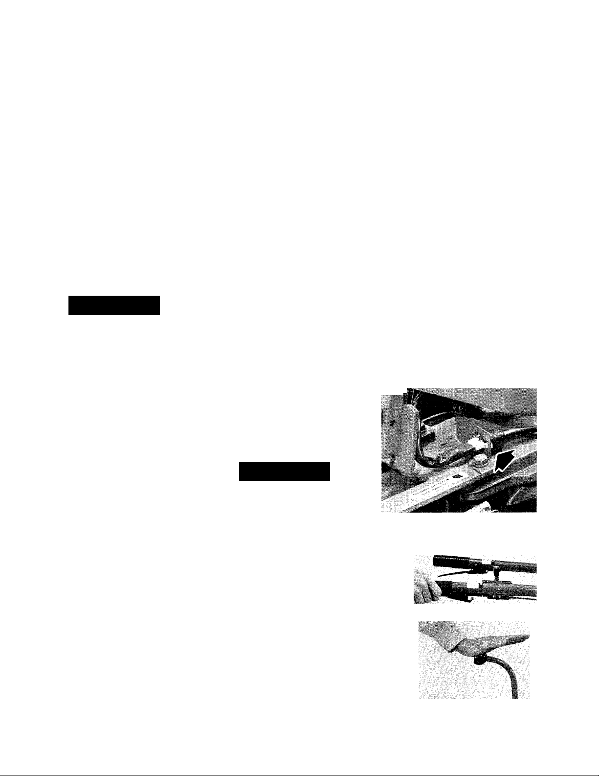
2. Check to make sure that the
Forward Interlock Wire Harness
OPERATION OF TILLER
plug at the bottom of the handle
bars is firmly connected to the wire
harness receptacle located on the
top, right side of the transmission.
See Photo 3-2.
3. Place the Wheel Speed Lever in
“SLOW” and the Tines/PTO Clutch
Lever in “DISENGAGE”.
4. Start the engine as described
on Pages 18-19. Set the throttle
lever in a “SLOW” running position
and ailow the engine to warm up.
5. Squeeze one of the Forward
Interlock Levers against the handle
bar grip and then push the Wheels/
Tines/PTO Drive Lever all the way
down to “FORWARD”. See Photo
3-3. As the tiller starts to move
r
3-2: Check for good connection be
tween plug and receptacle of Forward
Interlock Safety System.
3-3: Squeeze one Forward Interlock
Lever and then move Wheels/Tines/
PTO Drive Lever down to “FORWARD”.
17
Page 20

Starting and stopping the engine
forward, release the Forward Inter
lock Lever briefly. If the system
is working properly, the engine
should start to shut off when you
release the lever. If It does, quickly
squeeze the lever against the han
dlebar grip and then return the
Wheels/Tines/PTO Drive Lever to
the “NEUTRAL” position (tap or lift
the lever up and release It). Repeat
this test using the other Forward
Interlock Lever.
6. If the engine does not start to
shut off when the Fonward Inter
lock Levers are released, the sys
tem is not functioning correctly,
and you should stop the engine.
Cold weather operation
Before operating the machine in
cold weather (below 40 °F) you
should take the following steps to
protect your engine and transmis
sion from possible damage.
1. Use a lighter weight oil in the
engine crankcase. See “Engine Oil
Maintenance” in Section 6.
2. Allow the engine to warm up
thoroughly before putting it under
a load.
3. Use fresh, winter grade fuel
(gasoline suppliers change the
fuel blend seasonally).
4. Use the correct weight gear oil
in the PTO Power Unit transmis
sion. See “Transmission Gear Oil
Maintenance” in Section 6.
5. While the engine is warming,
place the Wheel Speed Lever in
“FREE WHEEL”, block the wheels
to prevent them from moving, and
remove the key (on electric start
models) and disconnect the spark
plug wire from the spark plug. Do
not operate the tiller or PTO Power
Unit again until the system is again
functioning properly. See Section 6
in this Manual for some simple
troubleshooting checks you can do
to correct a faulty Interlock system.
IMPORTANT
To avoid possible damage to the
Forward Interlock Safety System,
do not use high-pressure sprays
around the wire harness recepta
cle or neutral plunger assembly.
put the Tines/PTO Clutch Lever in
“DISENGAGE”. Then squeeze one
of the Forward Interlock Levers
against the handlebar grip and shift
the Wheels/Tines/PTO Drive Lever
into “FORWARD”. This will rotate
the drive shaft inside the transmis
sion and help to warm the trans
mission gear oil.
6. Do not try to move the machine
if the wheels are frozen to the
ground. First melt the ice with
warm water.
A DANGER
To avoid personal injury, do not run
engine in an enclosed or poorly
vented area. Engine exhaust con
tains carbon monoxide, an odor
less and deadly gas.
To start the engine:
IMPORTANT
Use the following steps to practice
starting and stopping the engine
ONLY. Do not attempt to drive the
tiller or PTO Power Unit until you
have read ALL of the operating
instructions in this Section and in
Section 5.
1. Place the Wheels/Tines/PTO
Drive Lever in “NEUTRAL” (Photo
3-4). To find “NEUTRAL” (while the
engine is not running), push the
lever down until it engages in
“FORWARD”. Then tap or lift the
lever up and release it.
2. Lower the Depth Regulator
Lever until the tines are off the
ground (Photo 3-4).
3. Put the Wheel Speed Lever in
either “SLOW” or “FAST” (Photo
3-4). Be sure to roll the wheels
while shifting the lever until the
wheels are engaged.
NOTE: If using a PTO driven sta
tionary attachment, put lever in
“FREEWHEEL” and place blocks
around all wheels to prevent
equipment from moving.
4. Move the engine throttle lever
forward, away from the “STOP”
position (Photo 3-4).
5. Put the Tines/PTO Clutch Lever
in the “DISENGAGE” position—
Photo 3-4. (Use the “ENGAGE” po
sition if you want the tines to turn
or if you want to apply power to a
PTO driven stationary attachment).
6. Move the choke control to the
“FULL CHOKE” position (Photo 3-5
or 3-6). NOTE: A warm engine may
start without choking.
18
Page 21
ENGINE THROTTLE
FORWARD INTERLOCK
LEVERS
OPERATION OF TILLER
2. Move the engine throttle lever
to the “STOP” position (and turn
the key to “OFF” on electric start
models). Remove the key for
safekeeping.
TINES/PTO
CLUTCH
3-4: Tiller and engine controls.
NOTE; Be sure that fuel tank shut
off valve (see Page 15) is in “OPEN”
position.
7. For recoil start engines;
(a) Stabilize machine by placing
your free hand on the fuel tank
of the Briggs & Stratton Engine
or on the air cleaner cover of
the Kohler Engine.
(b) Use your other hand to slowly
pull the starter rope until you
feel resistance. Then rapidly
pull the rope. (Look behind you
before pulling rope out.) Let
the rope rewind slowly after
each start attempt.
8. For electric start engines;
(a) Turn the key to the “START”
position. Do not hold the key at
“START” for longer than a few
seconds as prolonged crank
ing can damage the starter
chok'éI
i
OFF
FULL ^
■ 'CHOKEpP^
3-5: Choke control on 7 HP Engine.
WHEELS/TINES/PTO
DRIVE LEVER
WHEEL SPEED LEVER
/
DEPTH REGULATOR
LEVER
motor if cranked more than 15
seconds per minute.
(b) When the engine starts, release
the key and it will return to the
“RUN” position.
9. If the engine fails to start in four
or five tries, let the engine set for
10 minutes and repeat the start
ing procedure.
10. When the engine starts, slowly
move the choke control (if used) to
the “HALF CHOKE” and then to
the “CHOKE OFF” positions.
11. Move the throttle lever to the
“SLOW” position and let the engine
warm up.
STOPPING THE ENGINE:
1. To stop the wheels and tines at
any time, move the Wheels/Tines/
PTO Drive Lever into the “NEU
TRAL” position and then release
both Forward Interlock Levers.
3-6: Choke control on 8 HP Engine.
IMPORTANT
If turning the key to “OFF” or mov
ing the throttle lever to “STOP"
does not shut the engine off, you
can move the choke control to the
“FULL CHOKE” position. This will
flood the engine and cause it to
stall. Use this procedure only in
emergencies, as continued use can
be harmful to your engine.
Starting the Electric Start Engine with the recoil starter rope
If necessary, the electric start
engine can be started with the re
coil rope. However, before doing
so be sure to follow the procedure
below that applies to your particu
lar situation.
1. If the battery is in good condi
tion (not “dead” or damaged), you
can leave it on the tiller which
allows it to be recharged during
engine operation. But, before start
ing the engine with the recoil rope,
make sure that the battery is filled
to the correct level with electrolyte
and that all of the cables and wires
are properly connected.
2. If the battery is “dead” or dam
aged, then it should be removed
from the tiller and tested by a qual
ified battery mechanic. While the
battery is removed, keep the loose
terminal on the positive (+) battery
cable (if cable is still attached to
solenoid) covered with a wrapping
of electrical tape and secure the
cable to the frame of the battery
bracket. This will prevent any pos
sibility of sparking from the cable
terminal.
3. Before starting the engine with
the recoil starter rope, place the
key switch in the “RUN” position,
the engine throttle lever in the
“START” position, and the choke
control in the “FULL CHOKE” posi
tion (for cold starts).
19
Page 22

To operate the tiller
Now that you are familiar with
the operation of your engine, foilow these steps for operating your
tiller. When first practicing with
your tiller, please leave the Tines/
PTO Clutch Lever in the “DISEN
GAGE” position and put the Wheel
Speed Lever in the “SLOW” wheel
speed position.
A WARNING
To avoid personal injury, keep
hands, feet, legs and clothing away
from the revolving tines.
To begin tilling:
1. Start the engine by following
the previous engine starting in
structions. Be certain that the
Wheels/Tines/PTO Drive Lever is
in “NEUTRAL” before starting the
engine.
2. Test operation of Forward Inter
lock Safety System. See page 17.
3. Set the Depth Regulator Lever
to the desired digging depth and
increase the engine throttle speed
(when practicing with the tiller
leave the tines in the “TRAVEL”
position).
4. Move the Tines/PTO Clutch
Lever to the “ENGAGE” position
(when practicing with the tiller
leave the tines in the “DISEN-
GAGE” position).
5. For FORWARD MOTION of the
wheels and tines, squeeze and hold
one of the Forward Interlock Levers
(see Photo 3-7) against the handle
bar grip and then move the Wheels/
Tines/PTO Drive Lever down into
“FORWARD”.
6. As the tiller moves forward, re
lax and let the wheels pull the tiller
along while the tines do the dig
ging. Walk behind and to one side
of the tiller (walk on the side that is
not yet tilled to avoid making foot
prints in the freshly tilled soil),
and lightly, but securely, grip the
handlebars with one hand. See
Photo 3-8.
Allow the machine to work at its
own pace. Pushing it forward in an
attempt to make it go faster will
only make the tiller harder to con
trol. Also, please do not push down
on the handlebars in an attempt to
force the tiller to dig deeper. Doing
so takes the weight off the wheels,
reduces traction, and causes the
tines to attempt to propel the tiller
instead of just digging. This can
if / :/
' " V / ■ ■ '' ■ ’'■ '***■
1- 1
cause the tiller to hop and skip
rapidly across the garden.
7. TO STOP FORWARD MOTION:
Tap or lift the Wheels/Tines/PTO
Drive Lever up to “NEUTRAL” and
then release BOTH Forward Inter
lock Levers.
8. TO STOP FORWARD MOTION
IN AN EMERGENCY: Let go of ALL
handlebar control levers (this will
shut off the engine).
9. For REVERSE MOTION:
(a) Do not till while in “REVERSE”.
(b) Put the Wheels/Tines/PTO
Drive Lever in “NEUTRAL” and
reduce the engine throttle
speed. Make sure the area be
hind you is clear.
Put the Wheel Speed Lever in
(c)
the “SLOW” position.
Put the Tines/PTO Clutch Lever
(d)
in “DISENGAGE”.
Lift the handlebars until the
(e)
tines clear the ground and then
lift and hold the Wheels/Tines/
PTO Drive Lever all the way up
(you do not need to squeeze a
Forward Interlock Lever while
in “REVERSE”).
V
. £
■
3-7: Squeeze one Forward Interlock
Lever before engaging Wheels/Tines/
PTO Drive Lever in “FORWARD”.
3-8: Guide tiller with one hand.
20
Page 23

A CAUTION
TO HELP AVOID PERSONAL INJURY
OR DAMAGE TO EQUIPMENT:
• Always make sure there are no
obstacles behind you before oper
ating in “REVERSE”.
• Disengage the tines, reduce the
engine throttle speed and move
the Wheel Speed Lever into the
“SLOW” position before operating
in “REVERSE”. Avoid using “FAST”
wheel speed until you are sure
you can control the machine at
this faster speed.
10. TO STOP REVERSE MOTION:
Release the Wheels/Tines/PTO
Drive Lever and it will automatically
return to the “NEUTRAL” position.
(The Forward Interlock Levers will
not stop “REVERSE” motion.)
TO STOP THE ENGINE:
Move the engine throttle lever
to the “STOP” position (and turn
the key to “OFF” on electric start
models). Remove the key for safe
keeping.
Turning around
It’s easy to turn your tiller
around. All you have to do is find
the balance point between the en
gine and the tines and then let the
power driven wheels do the work
as you push sideways on the
handlebars in the direction of
your turn.
Practice the following maneuver
in a large open area before taking
your tiller into the garden.
A WARNING
To help avoid personal injury, al
ways put the Tines/PTO Clutch
Lever in the “DISENGAGE” posi
tion before turning the tiller around.
1. At the end of a row, put the
Wheels/Tines/PTO Drive Lever in
“NEUTRAL” and reduce the engine
throttle speed.
2. Put the Tines/PTO Clutch Lever
in “DISENGAGE”.
3. Resume forward operation and
lift the handlebars until the tines
are out of the ground. Then, using
the wheels as a pivot point to bal
ance the engine and tines, PUSH
the handlebars to swing the tiller
around. Af all times, be careful to
keep your feet and legs away from
the tines (which should be disen
gaged). Let the powered wheels do
the work ... the inside wheel will
pivot in place while the outside
wheel drives the machine around.
See Photos 3-9 and 3-10.
NOTE: Use “REVERSE” if neces
sary, to turn in a limited space.
4. When the turn is completed,
shift into “NEUTRAL” and lower
the handlebars. When you are
ready to begin a new row, put the
Tines/PTO Clutch Lever in the
“ENGAGE” position and resume
“FORWARD” operation.
0
W-.'Îlî’
. ■ ‘V .
.•i U’.
3-9: Lift the handlebars and find balance point Then PUSH 3-10: Starting a new row.
handlebars to swing tiller around.
.ft
'9i‘
r
21
Page 24
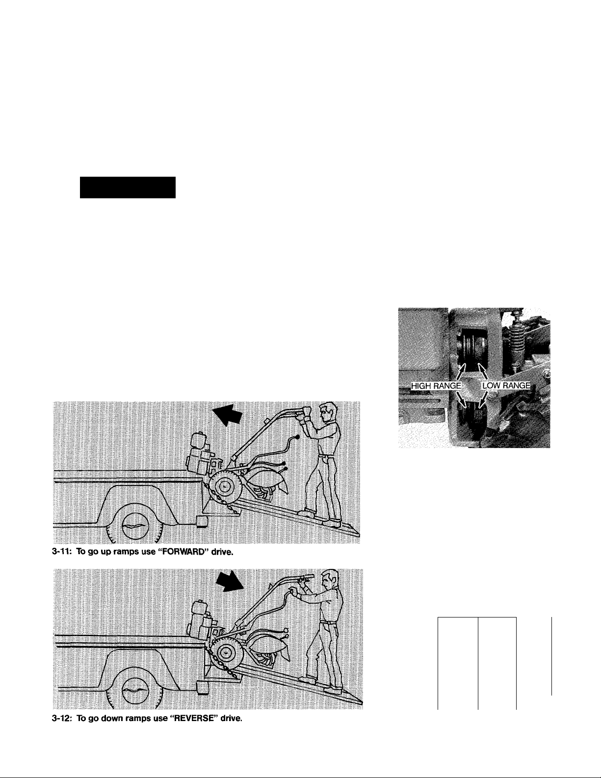
Transporting your tiller
The power driven wheels allow
you to easily move your tiller to
and from your garden when the
engine is running. Or, you can
move the tiller (on level ground)
without the engine running by us
ing the “FREE WHEEL” position on
the Wheel Speed Lever.
A WARNING
To help avoid personal injury, al
ways put the Tines/PTO Clutch
Lever in the “DISENGAGE” posi
tion before transporting, loading or
unloading the tiller.
To transport tiller:
1. Place the Tines/PTO Clutch
Lever in the “DISENGAGE” position.
2. Move the Depth Regulator Lever
all the way down to the “TRAVEL”
setting.
3. If using engine power, select the
“SLOW” or “FAST” wheel speed
position on the Wheel Speed Lever
and use the Wheels/Tines/PTO
Drive Lever to drive the wheels.
4. If the engine is stopped, put
the Wheel Speed Lever in “FREE
WHEEL” and manually move the
machine.
To load or unload tiller:
1. Use loading ramps that are wide
and strong enough to support both
the machine and the operator (ma
chine weighs between 280 and
325 pounds).
2. Place the Tines/PTO Clutch
Lever in the “DISENGAGE”
position.
3. Put the Wheel Speed Lever in the
“SLOW” wheel speed position and
reduce the engine throttle speed.
4. TO GO UP RAMPS, use “FOR
WARD” drive and follow the tiller
up the ramps (Figure 3-11).
5. TO GO DOWN RAMPS, use “RE
VERSE” drive and back down the
ramps. Never go down the ramps
in “FORWARD” drive as the tiller
could tip forward, exposing you to
the tines (which should be disen
gaged). See Figure 3-12.
Changing belt speeds
Your Tiller has both “LOW” and
“HIGH” speed belt ranges. By
moving the belt from one range to
the other you can obtain a total of
four different forward wheel speeds
and two different tine speeds. These
extra wheel and tine speeds permit
you to tailor your tiller’s action to
your specific needs in the garden,
with less strain on the engine.
Changing from one belt range to
the other is simply a matter of mov
ing the belt from one set of grooves
on the engine and transmission
pulleys to the other set of grooves.
See Photo 3-13. This change can
be made very quickly in the field
and without any tools.
3-13: Belt range positions.
By combining the use of the
“LOW” and “HIGH” speed belt
ranges with the “SLOW” and
“FAST” speed positions on the
Wheel Speed Lever, you can ob
tain four different forward wheel
speeds (Figure 3-14). The two dif
ferent tine speeds (Figure 3-14)
are determined by the belt range
position alone.
At 3000 RPM (Revolutions Per Minute)
engine speed, the w/heel and tine speeds are:
WHEEL
SPEED
BELT
POSITION
Low Range
Low Range
High Range
High Range Fast
3-14: Wheel and tine speeds.
LEVER WHEEL TINE
POSITION SPEED
Slow
Fast 1.2
Slow
.5 MPH 146 RPM
.7 MPH
1.72 MPH 200 RPM
SPEED
MPH 146 RPM
200 RPM
22
Page 25
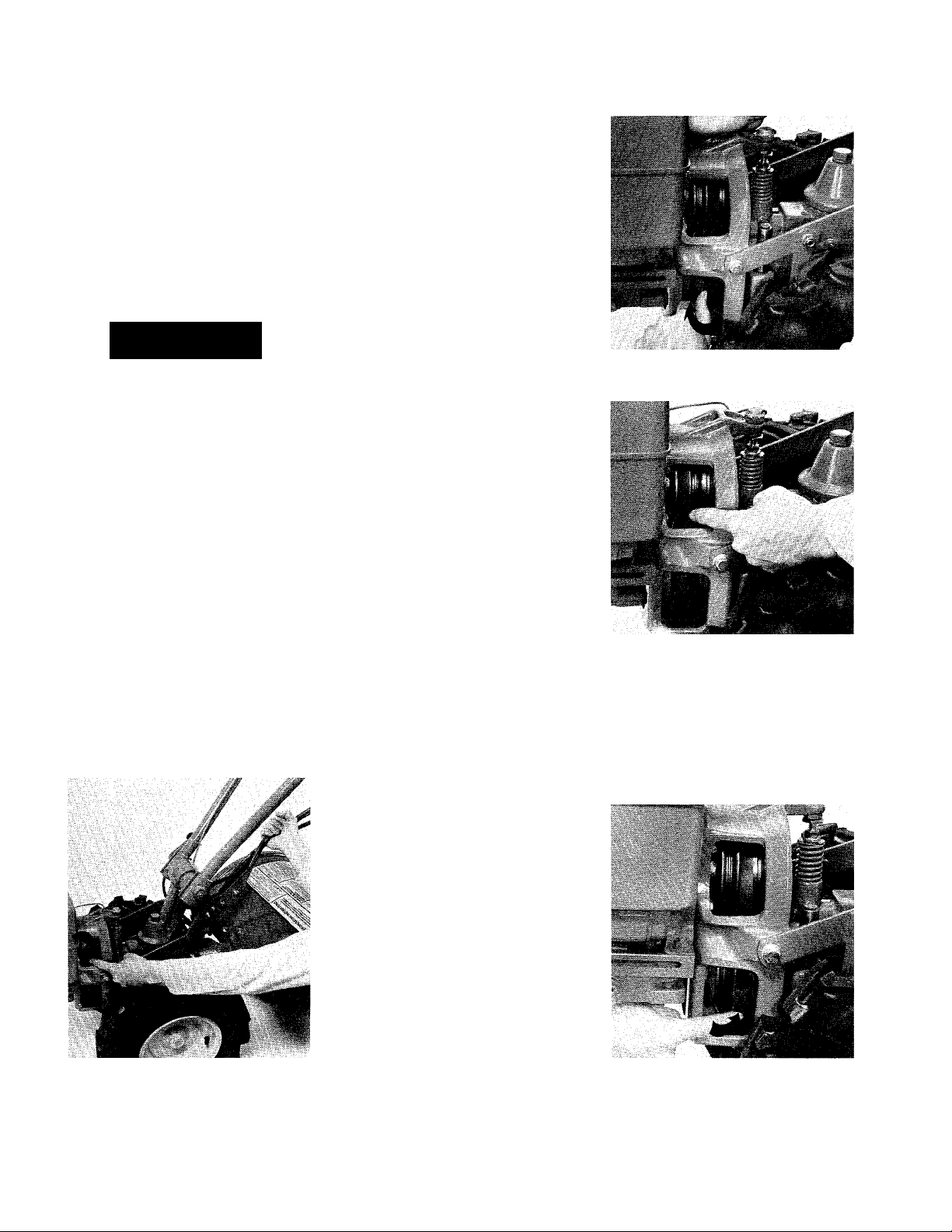
When the tiller is operating in
“REVERSE”, the wheels and tines
are powered by the rubber reverse
disc and not the belt. Therefore,
you have only two reverse speeds
as determined by the “SLOW” and
“FAST” positions of the Wheel
Speed Lever.
To change from “LOW” range to “HIGH” range:
Proper belt tension is critical to
good performance. Check the ten
sion after the first 2 hours of new
operation and every 10 hours
thereafter. See "Drive Belt Mainte
nance" in Section 6.
OPERATION OF TILLER
IMPORTANT
A WARNING
To help avoid personal injury, stop
the engine, remove the electric start
key, disconnect the spark plug
wire, and let the engine and muffler
cool before changing belt speeds.
Now go to the other side of the
tiller and finish seating the belt In
the groove.
3. On the left side of the tiller, work
the belt part way into the forward
groove of the engine (upper) pul
ley. See Photo 3-16. Then go to the
other side and finish seating the
(lower) pulley. See Photo 3-15.
1. Place the Wheels/Tines/PTO
Drive Lever in “NEUTRAL”.
2. While kneeling on the left side
of the tiller, create slack in the belt
by reaching over to the right side
of the pulleys and pushing in on
the center of the belt with your
finger. Then use your left hand to
work the belt part way into the
forward groove of the transmission
To change from “HIGH” range to “LOW” range:
belt. NOTE: If additional clearance
is needed to fit the belt over the
engine pulley, simply raise the
Wheels/Tines/PTO Drive Lever into
the “REVERSE” position. This will
lower the engine pulley.
4. Check both sides of the pulleys
to make sure that the belt is fully
seated in the “HIGH” range grooves
of each pulley.
3-15: Move belt on transmission puiiey into forward groove.
3-16: Move beit on engine puliey into
forward groove.
3-17: With drive lever held in “RE
VERSE”, move belt on engine pulley
into rear groove.
1. Place the Wheels/Tines/PTO
Drive Lever in “NEUTRAL”.
2. Stand on the left side of the
tiller and use your right hand to
hold the Wheels/Tines/PTO Drive
Lever up in the “REVERSE” posi
tion. Then use your left hand to
move the belt part way into the
rear groove of the engine (upper)
pulley. See Photo 3-17. Now go to
the other side of the tiller and fin
ish seating the belt in the groove.
3. While still holding the drive lever
in “REVERSE”, move the belt into
the rear groove of the transmission
(lower) pulley. Do this on both sides
of the tiller. See Photo 3-18.
4. Check both sides of the pulleys
to make sure that the belt is fully
seated in the “LOW” range groove
of each pulley.
23
3-18: Move beit on transmission puiiey into rear groove.
Page 26

Choosing wheel and tine speeds
Your tiller offers a wheel and tine
speed combination for every tilling
task and situation in the garden.
With a little experimenting, you can
soon find the proper tilling depth,
engine throttle setting, and wheel
and tine speeds that are just right
for the piece of soil you are work
ing on. What this means is;
1. You advance the throttle lever to
keep the engine running at a suffi
cient power level to do the job.
2. You have the depth regulator
set in a notch which is not so deep
WHEEL SPEED AND BELT RANGE SELECTION GUIDE
IMPORTANT: For correct wheel speed and belt range choices when using attachments or
accessories other than the tines, read the Owner/Operator Manual provided with the attachment
or accessory.
that it causes the engine to labor
or causes the tiller to jump.
3. You have the tines turning over
fast enough to really break up the
soil with a minimum number of
passes. When your tiller is working
properly, you can hear that the
engine is not laboring very hard
and see that the tines are breaking
up the soil into small, thoroughly
tilled bits. At the proper match
of wheel and tine speeds, you will
get the job done quickly, and
achieve results which are better
and more satisfying.
To help guide you in your selec
tions of wheel and tine speeds,
please refer to the following chart.
A WARNING
The “HIGH” belt range and “FAST”
wheel speed combination will
propel the tiller at a fast pace.
To help avoid personal injury when
first using this belt range/wheel
speed combination, reduce the en
gine throttle speed setting to a
slower setting.
SLOW GEAR, SLOW GEAR, lAST GEAR,
LOW RANGE HIGH RANGE LOW RANGE HIGH RANGE
Till in sod
Till hard clay
Till in cornstalks
Till in cover crops
Till in sod Prepare last time over Prepare seedbeds for
Till hard clay seedbed for planting planting cover crops
Till in cornstalks (in vegetables and cover
most cases, much crop Cover seeds with less
FAST GEAR,
Mixing in lime
Prepare very deep faster) Cover seed in wide row holding up on handle-
seedbed Till in cover crops or plot planting. (In bars (faster than low
Till in stony soil (faster, better job in some soil, handlebars range)
Till in residues and
most soils)
organic matter Prepare seedbeds (in
must be held up to Cultivate (excellent.
keep from going too
saves engine because
Mix in fertilizers most soils better and deep) you don’t have to run
and manures faster) Hill and furrow very well it wide open, nor hold
Till in stony soils Raise beds easily up handlebars—with
Make raised beds Cultivate (In some soil.
rare exception—
Mix in fertilizer you may have to hold because it travels
Pull hiller in hard clay
soil
up on handlebars to faster and stays on
avoid going too deep) top)
Mix fertilizer and manure Handy in keeping large Keep large areas tilled
Till in residues and
organic matter
areas tilled and pre- and ready through
pared for a season to
improve soil
Till in some organic
matter in good soil
Mix in lime
Cultivating between
raised beds with
hiller/furrower
summer (saves a lot
of time)
Till in some organic
matter.
Moving tiller from one
place to another
Cultivating between
raised beds with
hiller/furrower.
24
Page 27

SECTION 4: Tliiln i the
In this Section you will find tips
and suggestions to help you get
the greatest possible satisfaction
from your new tiiler.
Tilling depths
When you start to till in the gar
den, remember to take it easy. Do
not try to take too deep a cut on
the first pass through sod or hard
ground that has not been tilled for
several months or years. It is almost
impossible to dig down four or five
inches on the first pass through
untilled soil. So, you should start
tilling at a very shallow depth regu
lator setting, perhaps only an inch
or two deep the first time.
In each succeeding pass, you
can go down a few more inches,
gradually working down to the
depth you want (watering your gar
den a few days prior to tilling will
make the going much easier). At
any time, if you have difficulty get
ting down really deep, let the newly
worked soil set for a day or two.
When you return to it, the tilling will
be easier.
it is best not to work the soil
when it is too wet. Doing so will
produce large soil clumps that will
later dry out and become hard.
Test the soil by squeezing it in your
hand. If it compresses easily into a
ball, it is too wet to till. If time will
permit, always wait for the ground
to dry before tilling.
A WARNING
To help avoid personal injury, be
aware that the tiller may unex
pectedly bounce upward or jump
forward and be propelled away
from you if the tines should strike
extremely hardpacked soil, sod,
frozen ground, or buried obstacles
such as large stones, roots or
stumps. If you are in doubt about
the tilling conditions, always use
the following operating precautions
to assist you in maintaining control
of the tiller:
• Walk behind and to one side of
the tiller, using just one hand on
the handlebars. Relax your arm,
but use a secure hand grip.
• Use shallower depth regulator
settings, working down gradually
deeper with each tilling pass.
• Use slower wheel, tine and en
gine speeds.
• Clear the tilling area of all large
stones, roots and other debris.
• Avoid applying downward pres
sure on the handlebars. If neces
sary, apply slight upward pressure
to prevent the tines from digging
too deeply.
• Always avoid contacting hardpacked soil or sod at the end of a
row by reducing the engine speed
and lifting the handlebars to raise
the tines out of the soil.
• IN AN EMERGENCY, stop the
tines and wheels by placing the
Wheels/Tines/PTO Drive Lever in
“NEUTRAL”. If you cannot reach
the lever or have lost control of the
tiller, LET GO of the handlebars
and all controls and do not attempt
to restrain the machine. The For
ward Interlock Safety System will
stop the engine.
aerated soil, it will also help to
prevent many weed seeds from
germinating.
When preparing the soil, go over
the same path twice in the first
row, then overlap one-half the till
er’s width on each succeeding
pass. See Figure 4-2. After going
up and down the rows in one direc
tion, make a second pass at a right
angle across your earlier rows
(Figure 4-3). Again, overlap each
pass to really pulverize the soil. (In
very hard ground, it might take
three or four passes before you
make much headway.)
If your garden is not wide enough
to till lengthwise and then cross
wise, then you should first overlap
each pass by one-half a tiller width,
followed by successive passes of
one-quarter width. This overlap
ping method will assure you of
thoroughly breaking up the soil.
If you have plans to expand your
garden for next season, then the
best time to bust up sod is in the
4-2: Use overlapping technique on
first pass.
4-1: Use shallow depth regulator set
tings when first starting out.
Seedbed preparation
In a well-prepared seedbed, the
soil should be as loose and finely
textured as possible. Ideally, the
soil should be tilled a few weeks
prior to the planting date. Then,
after a few days, it should be tilled
again. Finally, till the area one more
time on the day you are going to
plant. This procedure will not only
produce a finely textured, well-
25
4-3: Make a second pass at a right
angle to first pass.
Page 28

fall. Doing so will allow the sod or
tough surface growth to be com
pletely broken down by the time
spring rolls around. (Sod busting
can be done even in late fall—as
long as the ground isn’t frozen.) If
there is some growing season left,
then you should plant a cover crop
(see “Power Composting” in this
Section), which will help protect
the soil over the winter.
Avoid making footprints
When making final tilling or cul
tivating passes through the garden,
always try to walk on the side that
is not yet finished. This will avoid
leaving footprints in the freshly tilled
soil. See Photo 4-4.
Eliminating footprints contributes
much more than just good appear
ance to your garden. It aids in
preventing soil erosion and avoids
“planting” unwanted weed seeds
right back in your newly tilled
ground. It also leaves your soil nice
and loose, so that vegetable and
flower roots can penetrate it easily.
4-4: Try to avoid leaving footprints.
Cultivating
If you plan carefully before plant
ing, you can leave enough room
between the plant rows for later
cultivating with the tiller... all but
eliminating most hand-weeding
and hoeing chores.
The tiller hood measures 22V2"
across, so leave that much dis
tance between the rows, plus
enough extra for plant growing
(QQOQ
~ODOQ)
COG^OO
4-5: Leave room between rows for
cultivating.
room (especially for bushy crops
such as beans, tomatoes and
peas). See Figure 4-5.
Cultivating can begin as soon as
your seedlings appear above the
ground; then cultivate as often as
once a week. The day following a
rain shower is an excellent time to
cultivate, as long as the plants are
dry. You should avoid working in
the garden when the plants are
wet since diseases, blights and
rusts can easily be spread among
the wet plants with your hands,
clothes, or even the tiller.
Shallow cultivation is very impor
tant! Do not till deeper than one or
two inches, to avoid injuring the
roots of nearby plants. If you no
tice that the tines are digging too
deeply even though the Depth Reg
ulator Lever is in one of the top
notches, then you may have to lift
up on the handlebars slightly (run
ning your tiller in the “HIGH” belt
range will help to prevent the tines
from going too deep).
Power composting
It is essential that a garden be
fed something if it is to be bounti
ful year after year in the same loca
tion. You must replenish the plant
nutrients—primarily nitrogen, phos
phorous and potassium—that you
remove from the soil in the form of
harvested vegetables and fruits.
A simple and very effective way
to do this is to use your tiller to
chop, blend, and turn under all
kinds of organic matter including
crop residues, leaves, grass clip
pings and “green manure” cover
SOIL ENRICHMENT IDEA
MULCH—If you use an organic
mulch during Iho growing .sfM.son.
it can lie tilled under with your
crop residues at the end of the
growing season PopulfK mulches
include hay. old straw, grass t'linpings, and other dense organic
n’atcrials. ri:l this m.stter under to
a depth of 4 to 6 inches.
crops (clover, annual rye, grains,
alfalfa, buckwheat, etc.). This or
ganic matter will decompose dur
ing the non-growing season and
add important nutrients to the soil.
See Photo 4-6.
When power composting, set the
depth regulator at the deepest set
ting possible, without making the
engine labor too hard or causing
the tiller to jump. Crop residues
should be tilled into the soil as
soon as possible after harvesting,
since tender, moist green matter is
tilled more easily. We recommend
that you use the “HIGH” belt range
and “SLOW” wheel speed gear
when power composting. If you
find the tines aren’t working effec
tively in the “HIGH” belt range
setting, then try tilling in the
“LOW” range.
After all power composting has
been completed, you should plant
a cover crop to protect your soil
during the non-growing season.
Then in the spring, the cover crop
can be tilled under a few weeks
prior to planting, providing more
organic matter to help feed the soil.
4-6: After harvest, till under crop resi
dues to add nutrients to the soil.
26
Page 29

TILLIIG iff. W
SPECIAL TROY-BiLT GAROENIRG TECHNIQUE
How to till under standing
cornstalks
As soon as your corn has been
harvested, the stalks should be
turned into the soil while they are
still green. Don’t wait until the stalks
are dried out, they are tougher to
handle and the roots pull out more
easily. YOU DON’T WANT TO PULL
THE ROOTS OUT BY HAND, OR CUT
THE STALKS, BEFORE TILLING. It is
the action of the stalk (held in place
by its root structure), being chopped
against the soil that makes it so
easy for your tiller to cut it down
and chop it up, partially burying
much of the cornstalk material in
the first pass.
Knocking down cornstalks and
tilling them under is not difficult once
you understand three basic princi
ples. First, the stalks should go in
between the left wheel and the trans
mission case, as shown in Photo 2.
(The right wheel will not work be
cause the stalks might interfere with
the carburetor, air cleaner, or throt
tle linkage.)
Second, each pass should over
lap one-half a tiller width over the
ground tilled on the previous pass.
And third, till just as deeply as you
did when preparing the ground for
planting. This usually means that
the depth regulator is pulled all the
way UP to the deepest setting pos
sible, depending upon the condition
of the soil. Generally, the “LOW”
or “HIGH” belt range and “SLOW”
wheel speed gear will be best for
tilling under cornstalks. However,
some folks will even be able to use
the “LOW” belt range and “FAST”
wheel speed gear, depending upon
the size of the stalks and the condi
tion of the soil.
Allow the tilled-in cornstalks to
lay in the ground undisturbed for a
week to give the active soil life a
chance to start decomposition and
digestion of the stalks. Then, till in
the residue as deeply as possible.
This will probably take only one
overlapping pasis through the gar
den. Four or five days after this final
tilling, you can sow a cover crop,
such as annual rye grass.
(1) Make first pass alongside first row
with RIGHT wheel up close to, but not
touching any cornstalk. The purpose of
this pass is to loosen up soil in prepa
ration for next pass.
(4) The fourth pass will be back down
between rows, overlapping one-half the
No. 3 pass.
(2) Make second pass with stalks in
between LEFT wheel and transmission
case (overlap first pass by one-half tiller
width). This pass will knock down stalks
and cut some into one or two-foot
lenoihs. partially burying them
(6) Make fifth pass alongside next row
of cornstalks, with right wheel up close
to, but not touching stalks.
?7
(3) On third pass, go back over stalks
that are lying down, but this time from
opposite direction. This will bury much
of the residue 3 or 4 inches under the
soil.
'Av'» , ..
(S) ~he sixth pass will start to knock
down the next row of stalks. Repeat
previous steps until all rows are down
and buried.
Page 30

Clearing the tines of debris
Your Bolo Tines feature a self
cleaning action which eliminates
most tangling in the tines. But oc
casionally, dried out grass, stringy
stalks, or tough vines may become
tangled. It isn’t necessary to re
move all the residue, but don’t let it
build up to a point where it chokes
off the action of the tines.
You can avoid most tangling
problems by setting the depth reg
ulator deep enough to get maxi
Tilling up and down slopes
If you must garden on a moderate
slope, then the best way to do so is
by planting rows up and down the
slope. Tilling vertically on a slope
permits you to use the entire area for
your seedbed, as well as to provide
enough room between rows so that
you can cultivate between them (you
lose these valuable benefits when
you terrace garden, which is dis
cussed further on). See Photo 4-7.
Growing a garden vertically on a
slope does not involve much of a
soil erosion problem, as long as you
put in enough organic matter to im
prove the moisture holding ability of
your soil and you do not leave foot
prints or wheelmarks. Soil in this
condition is loose enough to pre
vent packing, and is held together
well enough by those organic mate
rials so that it readily absorbs water.
When tilling vertically on a slope,
try to make the first pass in an uphill
direction. The tines dig in much more
deeply going uphill than when going
downhill. In soft soil or weeds, you
may have to lift the handlebars up
slightly as you go uphill. When going
back down the slope, overlap your
first pass by about half the width of
the tiller. For best results, use the
“HIGH” belt range and “SLOW”
wheel speed setting while tilling up
and down slopes.
mum chopping action as the tines
chop the material against the
ground, and by tilling under crop
residues or cover crops while they
are still green, moist and tender.
Also, you might try swaying the
handlebars laterally from side to
side about 6 to 12 inches while
continuing to power compost. This
“fishtailing” action will often clear
the debris out of the tines.
If the tines become tangled.
A CAUTION
TO AVOID PERSONAL INJURY
• Do not operate the tiller on a
slope that is too steep for safe oper
ation. Go slowly and make sure you
have good footing.
• Wear footwear that will increase
stability and reduce slippage.
• Do not use the “FAST” wheel
speed position while on sloping
ground.
• Do not shift the Wheel Speed
4-7: Tilling on a moderate slope.
STOP the engine and remove the
tangled material by hand. A small
pocket knife or linoleum knife will
help you to cut away the material.
A WARNING
To help avoid personal injury, stop
the engine, remove the electric
start key and disconnect the spark
plug wire before attempting to
clean the tines by hand.
OR DAMAGE TO EQUIPMENT:
Lever when heading up or down a
slope. If the lever is accidentally
placed in “FREE WHEEL”, the ma
chine could roll out of control.
• To prevent engine damage due to
oil starvation, make sure that the
proper oil level is maintained during
all uphill tilling operations. Checkthe
oil level after every one-half hour of
operation.
28
Page 31

Terrace gardening
If a slope is too steep or too short
for vertical tilling, it may be neces
sary to till across the slope in a
lateral direction. The best way to
achieve good results tilling across a
slope is to create terraces for your
garden (first, make sure that the
slope is not too steep for safe tilling).
Terraces should be about two or
three feet wide. This means you will
be able to plant one or two rows of
plants and later till under the crop
residues, but there may not be room
enough for cultivating with your tiller.
(If you make the terraces too wide,
you would be digging as much as a
foot into the uphill side of the ter
race and you would end up trying to
grow plants in poor subsoil).
Using the “LOW” belt range and
“SLOW” wheel speed gear, start to
terrace on the top of the slope and
work down, always keeping the up
hill wheel in the soft, newly tilled
soil. Each succeeding terrace is
started by walking below the terrace
you are preparing. In four or five
passes, your tiller can carve out a flat
and wide enough terrace for plant
ing. See Figure 4-8 and Photo 4-9.
Make sure that you don’t till the
WBBSSxBBIwSMm:
last 12-inches or more of the down
hill outside edge of each terrace.
Keeping this strip untilled will help
to prevent the terraces from break
ing apart and washing downhill. It
also gives you a walking path be
tween the terraces.
TiLyuG m inm gardei
'V
^ >• .'.AK ''
4-9: Terraces 2 or 3-feet wide are ideal.
UPHILL
LEAVE 12 Inches untilleo
¡;^ {REPE/ff PROCEDURE
DOWNHILL
4-8; How to make terraces in 4 or 5 passes.
Tilling across slopes without terraces
Tilling across a slope without
forming terraces is not recom
mended, but it can be done. How
ever, please think it over carefully
and see if it isn’t possible to till
vertically up and down the slope.
or to create terraces.
First, make sure that the slope is
not too steep to till safely at all.
Then, begin at the top of the slope
and overlap half of each tilled path,
always keeping the uphill wheel in
SOIL ENRICHMENT IDEA
TRENCH COMPOSTING-Trench
composting is easy with the op
tional Hiller/Furrower attachment
(see Section 9). Just dig a trench,
put in all manner of organic matter
and biodegradable household gar
bage and cover it up with soil. The
earthworms and microbial life in
the soil will consume it faster than
you might imagine.
the soft, newly tilled soil. Doing so
will help you keep the tiller more
stable. For best results, use the
“LOW” belt range and “SLOW”
wheel speed gear.
29
Page 32

SPECIAL TROY-BILT GARDENING TECHNIQUE
How to make raised beds for planting
It’s easy to make raised beds
with the optional Hiller/ Furrower
Attachment. Most crops can’t grow
in wet soil or heavy clay condi
tions because they can’t get the
air or nutrients they need for
growth. Raised beds can solve this
problem.
In addition, raised beds provide
a good irrigation system, discour
age soil compaction (from walking
near the plants), give your soil ear
lier and greater exposure to the
sun, increase the amount of top
soil around the crops, and provide
looser soil conditions for root
crops to grow in.
You can even try wide row plant
ing on raised beds. Rows can be
anywhere from 30 inches to 3 feet
apart, and 8 to 10 inches high.
Easy Steps to Raised Beds:
(1) Till under sod or crop residues
and work soil into a deep, smooth,
loose seedbed.
t-
(2) Place row-marker stakes at proper
intervals; attach hiller/furrower and
make your rows.
W-
■
■
I
(3) Hold the handlebars with both
hands and use faster tiller and engine
speeds.
SOIL ENRICHMENT IDEA
LEAVES—Leaves are an excellent
(and free) natural fertilizer that will
do wonders for your soil’s fertility
and texture. In the fall, spread 6 to
8 inches of leaves on the ground
and till them under. If enough grow
ing season is left, you can till once
again after a few days, and then
sow a cover crop.
(4) After planting seeds in ridges,
rake loose soil over top and firm soil
according to seed directions.
-
’*1 I
(5) Use furrower to make irrigation
trench at ends of rows.
SOIL ENRICHMENT IDEA
SHEET COMPOSTING-AII manner
of organic material including weedfree manure and mulches, leaves,
straw, hay and grass clippings can
be 'sheet composted” directly into
the soil. Just spread the material
around and till it under—it’s a lot
quicker than the lengthy compostpile process.
30
Page 33

SPECIAL TROY-BILT GARDENING TECHNIQUE
Try wide-row planting
Wide-row planting is a highly
productive gardening technique
that is worth trying. As the name
implies, it involves broadcasting
seed in bands anywhere from 10
inches to 2 or more feet wide,
rather than in traditional singlefile rows.
The greatest advantage to this
gardening method is that you have
more plants per area in your gar
den, which results in much higher
yields from the same amount of
space (see Photo 4-10). Typically,
you can grow anywhere from 3 to
4 (or more) times produce in the
same space normally set aside for
a single row.
In addition, when you plant crops
in wide rows, you automatically
shade the ground. Shading pre
vents most weeds from growing
and also holds moisture in the
ground. Wide rows also protect
the soil from temperature fluctua
tions and makes harvesting easy,
since you can sit and pick so much
produce from one spot.
It’s simple to plant and grow
wide-row crops. First prepare a
loose, smooth, fertile seedbed and
mark off your row with stringsPhoto 4-11. Hand broadcast the
seeds over the raked area as if
you were seeding a lawn (remem
ber to plant vegetable seeds a little
thinner than grass seed). Cover
them with soil from outside the row,
tamping it down firmly with a hoe.
If you’re planting larger seeds such
as peas or lima beans in wide
rows, you can run your tiller over
them, planting about 2 or 3 inches
deep. If you use your tiller for plant
ing, sow your seeds a little thicker
as some of them won’t get deep
enough to germinate. After tilling,
firm the soil.
Plant the larger-seeded crops,
such as beans or peas, with a little
care so you won’t have to thin later
on. For small-seeded crops, such
as lettuce and carrots, you can
easily thin as soon as they come
up by lightly dragging a steel
garden rake across the row about
V4-inch deep. You will also disturb
and kill many tiny weed seeds
that have begun to sprout near the
soil surface.
SIM ifee
•' 1/. ■ ' \ -
• It. ■ -
.. -T-
4-10: Wide-row planting on the right compared to sin
gle row on the left.
4-11: After preparing seedbed, mark off row area as
wide as you want, even up to 4-feet across.
™ ~ III! Ill III III llPlllllllllllillllllllillll MlliHIIMniflP~llil
V .
4-12: Wide-row planting really works, as evidenced by this lush growth of peas.
HERE’S ANOTHER SPACE SAVING METHOD: Planting in double (or even triple) rows is ?
another space saving idea that many Troy-Bilt Tiller owners use. Beans, for example, can be planted in
two rows spaced 6 to 8 inches apart. On either side of the double row, leave enough room for J
sidegrowth and later cultivating with your tiller. It is still necessary to thin seedlings according to the
seed company’s directions on the packet.
31
Page 34

SECTION 5:
As explained on Page 2 of this
Manual, your tiller can be con
verted into a self-contained PTO
Power Unit that is capable of
powering or towing other attach
ments besides the tine attachment
that came with your tiller. The in
structions given here will help you
become familiar with your PTO
Power Unit. Please read this Sec
tion thoroughiy.
Before trying to operate your PTO
Power Unit for the first time, make
sure that you have:
• Read and understand all of the
Safety Instructions in Section 1 of
this Manual and in the Owner/
Operator Manual that is supplied
with any attachment.
• Read and understand all of the
controls information and operating
procedures for the tiller and engine
as described in Sections 2 and 3
of this Manual.
• Read and understand all of
the assembly instructions, controis
information, and operating proce
dures for the attachment as de
scribed in the Owner/Operator
Manual that is supplied with the
attachment.
Removing and replacing the tine attachment
The foiiowing steps explain how
to remove and replace the tine at
tachment. The only tool you’ll need
is a %-inch wrench (at ieast 12inches long for adequate leverage).
There are two optional acces
sories avaiiable that make the
following steps easier. One is the
Kickstand Attachment which pre
vents the PTO Power Unit (engine
end) from falling forward when at
tachments are removed (Photo
5-2). The other is the Tine Attach
ment Cradie which provides a
handy support for the tine attach
ment when it is removed from the
tiller (Photo 5-3). For more infor
mation about these two acces
A CAUTION
TO AVOID PERSONAL INJURY OR
sories, please refer to Section 9 of
this Manual.
DAMAGE TO EQUIPMENT;
• Stop the engine, remove the
electric start key, disconnect the
spark plug wire and let the engine
and muffler cool before removing
or installing any attachment.
• Do not piace hands, tools,
or any object near or inside the
PTO access hole when the engine
is running.
• When removing and replacing
the tine attachment, be careful not
to cut yourself on the edges of the
tiller hood. Wear thick gloves for
maximum protection.
• When the tine attachment is re
5-2: Kickstand prevents engine from
tipping forward.
moved, always place the optional
tine cradle or a wood block or
other sturdy support beneath its
coupiing point to prevent the at
tachment from falling forward.
5-1: PTO Power Unit with tine attachment removed.
5-3: Tine Attachment Cradle.
To remove the tine attachment:
1. Make sure that the engine is
stopped, the electric start key is
removed, and the spark plug wire
is disconnected.
2. The equipment must be on level
ground.
3. Place the Wheels/Tines/PTO
Drive Lever in “NEUTRAL” (Photo
5-4).
32
Page 35

ENGINE THROTTLE
%. rC FORWARD INTERLOCK
WHEELS/TINES/PTO
I
WHEEL SPEED LEVER
J
jj-/.
TINES/PTO ■
DLUTCH LEVER ^
5-4: PTO Power Unit controls.
4. Place the Tines/PTO Clutch
Lever in “DISENGAGE” (Photo
5-4).
5. Place the Wheel Speed Lever in
“FREE WHEEL” (Photo 5-4).
6. Place a sturdy support under
the engine, or use the Kickstand
on your bumper (if so equipped) to
prevent the engine from tipping
down when the tine attachment is
removed. See Photo 5-5.
7. Using a %-inch wrench, loosen
the two swing-bolts that connect
the power unit transmission to the
tine attachment and swing the boits
outward. See Photo 5-6. NOTE: An
extra-iong (13") PTO Wrench is
avaiiable from our Parts Depart
ment. This heavy-duty wrench (Part
No. 2005) makes it quick and easy
to remove and replace the tine
attachment.
LEVERS
DRIVE LEVER
5-6: Move swing-bolts outward.
8. With one hand on the handle
bars of the power unit, tip the unit
forward about an inch whiie you
puil the tine attachment back a
short distance. This reieases the
guide pin on the power unit from
the guide pin mounting hole in the
tine attachment. See Photos 5-7
and 5-8.
IMPORTANT
Aiways store your tine attachment
in a levei position to avoid iosing
oil from the breather vent, locaieri
in the top of the dipstick.
9. Place the dust cap (supplied
with certain attachments), or some
plastic wrapping over the “dog”
clutch coupling of the tine attach
ment to prevent dirt and grime from
accumulating on the coupling.
10. The power unit is now ready to
accept other powered or non-
powered attachments. Refer to the
Owner/Operator Manual supplied
with each attachment for specific
instructions on how to install and
operate the attachment.
To replace the tine attachment:
1. Follow Steps 1-5 of the pre
vious tine attachment removal
instructions.
2. Place the two swing-bolts on
the power unit in the outward posi
tion, making sure that the washers
on the bolts are next to the bolt
heads.
3. Roll the power unit back to the
tine attachment and either put
down the optional Kickstand or
place a sturdy support under the
engine.
4. Remove the dust cap or protec
tive wrapping from the clutch cou
pling on the tine attachment.
5. Carefully align the alignment pin
on the power unit with the align
ment hole on the tine attachment
and bring the two units together
(Photo 5-8).
5-5: Block up engine.
5-7: Lift handlebars while pulling at
tachment away from power unit.
33
MOUNTING HOLE
5-8: Aiign guide pin with mounting
hole.
Page 36

PTO Power Unit operating instructions
6. Place the two swing-bolts in the
slots of the tine attachment. Alter
nating between the two bolts,
tighten each securely until the con
cave washers on the bolts are flat.
The bolts must be very tight. If
using a torque wrench, tighten
each to 70-80 ft. lbs. See Photo 5-9.
IMPORTANT
The swing-bolts must be kept very
tight at all times to prevent undue
wear on the “dog” clutch coup
lings, or on the alignment pin and
hole. Check bolts for tightness
after every 2-V2 hours of operation.
7. Remove the engine support be
fore attempting to drive the unit in a
forward direction.
A WARNING
To help avoid personal injury or
damage to equipment, read the
Owner/Operator Manual provided
with each attachment before at
tempting to install or operate the
attachment. The Manual provides
a detailed description of proper
use and operation, and points out
other important Safety Instructions.
The following instructions de
scribe how to operate the PTO
Power Unit ONLY. Read the sepa
rate Owner/Operator Manual for
each attachment carefully before
attempting to assemble, attach,
transport or operate the attach
ment. If you do not have a Manual,
call or write us for a replace
ment copy (be sure to supply us
with the serial number of your
attachment).
Some attachments have a drive
shaft or a hydraulic pump that is
powered by the engine on the PTO
Power Unit. These attachments are
called “Stationary Attachments”,
because they must remain in a
stationary position when being op
erated (they can be towed to the
work site by the power unit, as
described in “To Operate Non-
Powered Attachments”).
Other attachments are simply
pulled or towed behind the PTO
Power Unit. These attachments
are called “Non-Powered At
tachments”.
A WARNING
To help avoid personal injury, al
ways disengage the Tines/PTO
Clutch Lever before towing any
attachment.
Before starting engine:
IMPORTANT
Before operating in temperatures
below 40'^'F., refer to the "Cold
Weather Operation” instructions in
Section 3 of this Manual.
1. Put the Wheels/Tines/PTO Drive
Lever in “NEUTRAL”. To find “NEU
TRAL” (while engine is not run
ning), push the lever down unti it
engages in “FORWARD”. Then tap
or lift the lever up and release it.
(Photo 5-4).
2. Put the Tines/PTO Clutch in
“DISENGAGE”.
3. FOR STATIONARY ATTACH
MENTS ONLY:
(a) Put the Wheel Speed Lever in
“FREE WHEEL” and block ALL
wheels to prevent rolling of
equipment. (See Photo 5-4 and
Figure 5-10).
5-9: Tighten both swing-bolts.
Jl/l lC t
A.1^^ ut • i » M
5-10: Block wheels on power unit and stationary attachment.
34
- --LA-a C-AA' '_______.iu. L ¿/L«» ¿iV »
J.Lt
__
Page 37

5-11: Disconnect the Forward Inter
lock Wire Harness.
THE PTQ POWER UNIT
5-12: Connect wire from Stationary
Attachment to receptacle on
Power Unit
(b) On the Power Unit, unplug the
Forward Interlock Wire Har
ness that leads from the bot
tom of the handlebars to the
receptacle located on the top,
right side of the transmission
cover. See Photo 5-11).
(c) On the Stationary Attachment,
locate the interlock wire and
make sure that the surface of
the plug is clean.
(d) Connect the plug from the Sta
tionary Attachment to the re
ceptacle on the Power Unit.
See Photo 5-12. Make sure
that the connection is tight.
This connection allows you to
operate the Wheels/Tines/PTO
Drive Lever in “FORWARD”
without having to simultan
eously squeeze and hold one
of the Forward Interlock Levers.
4. FOR NON-POWERED ATTACH
MENTS ONLY:
(a) Put the Wheel Speed Lever in
either “SLOW” or “FAST” (roll
power unit.while shifting until
wheels are engaged). See
Photo 5-4.
(b) Make certain that the Forward
Interlock Wire Harness plug at
the bottom of the power unit
handlebars is connected to the
Forward Interlock Wire Har
ness receptacle on the top,
right side of the transmission
(Photo 5-13).
5. Move the Engine Throttle Lever
away from the “STOP” position and
use the Choke Control if the engine
is cold. Pull the Recoil Rope or use
the Key Switch (on Electric Start
models). When the engine starts,
move the Choke Control (if used)
to “CHOKE OFF” and let the en
gine warm up. (See Section 3,
“Operation of Tiller” for more de
tailed engine starting steps.)
6. For non-powered attachments
only, test Forward Interlock Safety
System. See page 17.
A WARNING
To avoid injury, do not run the en
gine in an enclosed or poorly
vented area. Engine exhaust con
tains carbon monoxide, an odor
less and deadly gas.
To operate Stationary Attachments:
1. Put the Tines/PTO Clutch in
“ENGAGE”.
2. To apply power to PTO driven
attachments, move the Wheels/
Tines/PTO Drive Lever down
to “FORWARD” (do not use
“REVERSE” with Stationary
Attachments).
3. TO STOP PTO POWER: Tap or
lift the Wheels/Tines/PTO Drive
Lever up to “NEUTRAL”.
5-13: Forward Interlock Wire Harness.
To Operate Non-Powered
Attachments (or to tow
Stationary Attachments):
1. To go forward, squeeze and
hold one Forward Interlock Lever
(Photo 5-4) and then move the
Wheels/Tines/PTO Drive Lever
down to “FORWARD”.
2. TO STOP FORWARD MOTION:
Tap or lift the Wheels/Tines/PTO
Drive Lever up to “NEUTRAL” and
then release BOTH Forward Inter
lock Levers.
3. TO STOP FORWARD MOTION
IN AN EMERGENCY: Let go of ALL
power unit controls (this will stop
the engine).
4. For reverse motion, first reduce
the engine speed and put the
Wheel Speed Lever in “SLOW”.
Then hold the Wheels/Tines/PTO
Drive Lever up. (Make sure the
area behind you is clear before
reversing.)
5. TO STOP REVERSE MOTION:
Release the Wheels/Tines/PTO
Drive Lever.
To stop engine:
Move the Engine Throttle Lever
to “STOP” (and turn Key to “OFF”
on Electric Start models).
35
Page 38

SECTION 6:
Your tiller and its engine require
regular care and maintenance if
they are to give you the many
years of service that you should
expect of them.
Most maintenance and repair
procedures are easy to do yourself
with the help of the step-by-step
RECOMMENDED MAINTENANCE INTERVALS
PROCEDURE HOURS HOURS HOURS HOURS HOURS
Check engine oil level
Clean engine cooling system
Test operation of Forward
Interlock Safety System
Check Forward Interlock Safety
System wires for loose
connections, fraying, or bare
spots
Check battery electrolyte level
and electrical connections
Recharge battery
Check drive belt tension
Check nuts and bolts
Clean tiller tine shaft
Lubricate tiller
Change engine oil*
Clean foam element air filter
Check paper element air filter
Check for oil leaks
Check gear oil level in Power
Unit and Tine Attachment
transmissions
Check Bolo Tines for wear
Check reverse disc for wear
Check air pressure in tires
Check spark plug
Replace paper element air filter
instructions found in this Section.
Of course, you can always call or
write the factory for expert advice,
or you can obtain factory author
ized service at one of our regional
stores, or from a nearby TROY-BILT
All references to “left” and “right”
sides of the tiller are given from
the operator’s position behind the
handlebars.
IMPORTANT
Tiller authorized dealer.
EVERY EVERY EVERY EVERY EVERY EVERY
USE 10 25 30 50 100
•
•
•
•
•
•
•
•
•
•
•
•
•
•
•
•
•
•
•
AS
NOTED
After every 5
operating hours
See Page 17 for
test procedure
Before and after
prolonged
storage
After first 2
break-in hours
After first 2
break-in hours
More frequently in
extremely dusty or
dirty conditions
More frequently in
extremely dusty or
dirty conditions
After first 2
break-in hours
After first 2
break-in hours
More frequently in
extremely dusty or
dirty conditions
'During new engine break-in period, change engine oil after first 5 hours of operation.
36
Page 39

Tighten bolts and nuts
MAIMTEMAMCE AND SERVICE
A WARNING
To help avoid personal injury, stop
the engine, remove the eiectric start
key, disconnect the spark plug wire,
and iet the engine and muffler coo!
before inspecting or servicing the
tilier or engine.
It’s a good idea to check for
loose or missing bolts, nuts and
screws after every 10 operating
hours. Failure to tighten or replace
fasteners can result in poor per
formance, equipment damage, or
oil leaks. If you need to replace a
fastener, be sure to refer to your
Parts Catalog for the correct size
and for any special grade specifi
cation. Most fasteners are available
locally, or you can order directly
from our Parts Department.
Most bolts, nuts and screws on
your tiller are easily visible. Please
refer to Photos 6-1, 6-1A and 6-2
for the following fasteners that re
quire special attention.
1. Check transmission pulley
mounting bolt (Photo 6-1). If
washer behind bolt head is loose.
then bolt must be tightened se
curely. To tighten bolt, insert a
punch or thick screwdriver into the
hole next to the bolt and wedge
the tool against the side of the
motor mount casting. This will pre
vent the pulley from turning as you
tighten the bolt.
2. Check jam nut on left side of
neutral plunger assembly (Photo
6-1 A). If loose, place one wrench
on head of bolt and tighten jam nut
with second wrench.
3. Check the three rear bearing
cap screws that are located under
neath the depth regulator mount
ing bracket assembly (“A” in Photo
6-2). If these screws are loose it
could cause an oil leak or exces
sive end play in the drive shaft.
At. Check the five bolts that fasten
the tiller housing cover to the left
side of the transmission (“B” in
Photo 6-2). If the bolts or cover are
loose, it could cause an oil leak. To
gain access to the housing cover,
you will have to remove the left
side tine holder. See “Bolo Tine
Maintenance” in this Section for
tine holder removal instructions.
5. Check the two swing-bolts that
connect the power unit transmis
sion to the tine attachment (“C” in
Photo 6-2). These bolts should be
checked after every 2-V2 hours of
operation. Failure to do so could
cause excessive wear to the locat
ing pin on the power unit, and
enlargement of the locating hole in
the tine attachment. The bolts must
be kept very tight. If you have a
torque wrench, tighten each to 70-
80 ft. lbs.
6. Check the locknut that fastens
the shifting linkage to the eccen
tric shifting lever (“D” in Photo
6-2). Do not tighten the locknut
against the eccentric lever. It
should be very close to, but not
touching the lever.
IMPORTANT
Screws or bolts that thread into
the transmission housing should
be coated w-th a non-hardening
gasket sealant (available at hard
ware or automotive supply storosi.
The sealant helps to prevent oil
from leaking past the threads.
1
6-1: Check bolt on transmission pulley.
6-1 A: Check jam nut on plunger assembly.
6-2: Gently tilt tiller forward to check these fasteners.
37
Page 40

Tiller lubrication
A WARNING
To help avoid personal injury, stop
the engine, remove the electric start
key, disconnect the spark plug
wire, and let the engine and muf
fler cool before inspecting or lubri
cating the tiller.
Proper lubrication of the tiller’s
mechanical parts is an essential
part of your maintenance program.
Lubrication should be done after
every 10 hours of operation.
Use ordinary motor oil (#30
weight, or lighter) where oil is
called for. Use a good quality
grease that contains a metal lubri
cant; however, regular grease is
acceptable. Do not over lubricate!
Excess lubricant merely collects
dirt which can cause wear to mov
ing parts. If you notice a build up
of dirt, clean the area and reapply
fresh oil or grease.
IMPORTANT
Do not permit oil or grease to come
in contact with the pulleys, the
drive belt, or the reverse disc. Do
ing so will cause the belt or disc to
slip on the pulleys.
The following numbers refer to
the numbered lubrication points
shown in Photos 6-3 and 6-4.
!' i
1. Oil the wheel shaft between the
wheel hubs and the transmission
housing (Photo 6-4).
2. Oil all of the pivoting and con
necting points on the Wheels/Tines/
PTO Drive Lever and the Wheel
Speed Lever (Photo 6-4). If Wheel
Speed Lever has a grease fitting on
pivot assembly, apply 2-3 strokes of
multi-purpose grease at beginning
and end of tilling season.
3. Grease the face of the belt ad
justment block (Photo 6-4).
4. Oil the back and sides of the
Depth Regulator Lever, including
the spring in the mounting bracket
(Photo 6-4).
5. Oil the entire length of the throttle
cable casing, starting up at the
Engine Throttle Lever and going all
the way down to the engine
(Photo 6-4).
6. Oil the threads on the Handlebar
Height Adjustment Lever
(Photo 6-4).
7. Grease the left and right side
engine mounting bars at the top, in
the middle, and at the bottom
(Photo 6-4).
8. Maintain a good supply of grease
inside the PTO (Power Take-Off)
access hole (Photo 6-3). If the
Tines/PTO Clutch Lever is hard to
shift, squirt some oil into the access
hole and move the lever back and
forth, trying to work the oil in
between the PTO coupling and the
sides of the housing. Call our
Technical Service Department if the
problem persists.
6-3: Use plenty of grease in PTO
access hole.
IV’ansmission gear oil
maintenance
A WARNING
To help avoid personal injury, stop
the engine, remove the electric
start key, disconnect the spark plug
wire, and let the engine and muf
fler cool before inspecting or serv
icing the tiller.
A. Checking for oil leaks
At every 25 hours of operation
you should check your tiller for oil
leaks. Look for accumulations of
dirty oil on the tiller or on the floor
where you’ve parked the tiller.
A little seepage or wetness
around a shaft opening or cover is
nothing to be alarmed about. How
ever, if there is a heavy accumula
tion of oil, or if oil drips while sitting
overnight, then you should replace
the worn seal or gasket right away
(first try tightening any loose
screws or bolts).
If you’re not sure how much oil
has been lost, then be sure to
cheok the oil level before operat
ing the tiller again. Operating the
tiller when the power unit or tine
attachment transmission oil levels
are low can result in serious dam
age to the transmissions.
When tilling during very hot
weather, the gear oil may heat up
and expand inside the transmis
sions. To allow for this oil ex
pansion, both the power unit
transmission and the fine attach
ment transmission have been
equipped with oil relief vents (see
Figure 6-5). These vents allow small
6-4: Tiller lubrication points (wheel removed for photo clarity only).
38
Page 41

MAINTENANCE AND SERVICE
amounts of oil to seep out, thus
relieving any excess pressure in
side the transmission. You should
not be concerned if you see oil
leaking from the twooil relief vents.
If you discover an oil leak, please
call or write our Technical Service
Department for parts and service
advice. (Be sure to ask about the
inexpensive seal drivers that are
available for the wheel shaft and
tine shaft oil seals.)
B. Checking gear oil levels
At every 30 hours of operation
you should check the levels of the
gear oil in the power unit and the
tine attachment transmissions.
Serious damage can result if the
transmissions are allowed to run
for even a short time without the
proper amount of oil.
The transmissions should be
cool when checking the oil levels
as the oil can expand if hot and
thus give a false reading. Also, the
power unit and tine attachment
must be connected when checking
(or adding) gear oil.
6-6: Remove oil level check plug.
3. If the oil level is correct, oil
should begin to seep out of the
hole as you remove the plug (be
patient in cold weather as the oil
may flow very slowly). If it does,
your check is finished and you
should securely replace the plug.
If there is no sign of oil, see the
“Adding Gear Oil” instructions
that follow these oil level check
ing procedures.
To check the Tine Attachment oil
level:
1. Make sure the tiller is on level
ground.
2. If the tiller has been operated
for 30 minutes or more within the
last hour, move the Depth Regula
tor Lever all the way down until it is
engaged in its highest notch. This
places the transmission in the cor
rect position to take a “Hot” oil >
level reading. J)4n^
If the tiller has not beenopef^
ated within the last two hours, you
should also place the Depth Regu
lator Lever in its highest notch.
Then, prop up the drag bar (located
below the tines) approximately 3%
inches off the ground (using a 2 " x
4 " board on edge works well). This
places the transmission in the
correct position to take a “Cold”
oil level reading.
3. Allow the tiller to rest in this
position for at least five minutes
for a “Hot” reading or two hours
for a “Cold” reading. (Allow more
time if the air temperature is
below 40 °F).
4. Clean the area around the tine
attachment dipstick so that no de
bris will fall into the transmission.
m
6-8: Tine attachment dipstick
markings.
5. Using a 9/16-inch wrench, re
move the dipstick as shown in
Photo 6-7. Wipe the dipstick with a
clean rag and note the “Hot” and
“Cold” range markings on one side
(Figure 6-8).
6. With the markings facing to the
rear of the tiller, gently lower the
dipstick straight down into the
sump hole until the end just tou
ches the drive shaft inside the hole
(Photo 6-9). Do not force, or try to
thread the dipstick into the hole.
Doing so will bend the dipstick and
result in an incorrect reading.
7. After a few seconds, carefully
remove the dipstick and look at
the markings. If taking a “Hot”
reading, the oil level should be
within, or slightly above, the “Hot”
range marking (checkered pat
tern). If taking a “Cold” reading,
the oil level should be within, or
slightly above, the “Cold” range
marking.
8. If the oil level is okay, your
check is finished and you should
securely replace the dipstick. If
the oil level is low, see the instruc
tions that follow.
' ’’ I'l
To check the Power Unit oil level:
1. Make sure the tiller is on level
ground. Pull the Depth Regulator
Lever up until the tines are resting
on the ground.
2. Use a %-inch wrench to remove
the oil level check plug that is
located above the wheel shaft on
the left side of the transmission
(Photo 6-6).
‘s^
6-7: Remove tine attachment dipstick. 6-9: Insert dipstick straight down.
OQ
Page 42

C. Adding or changing gear
oil
For small top-offs (a few ounces
or less), use SAE140, SAE 85W-140
orSAE 80W-90 weight gear oil with
an API rating of either GL-3 or
GL-5. For full gear-oil replacement,
use SAE 140 orSAE85W-140 gear
oil with an API rating of GL-3 only.
(Your tillertransmission was filled
with SAE 140 weight gear oil at the
factory.)
IMPORTANT
Do not use automatic trans
mission fluid or engine oil in the
transmission. These lubricants
are too light for transmission use.
The gear oil does not require
regular changing. Do so only if you
know, or suspect, that it has be
come contaminated with dirt,
sand, or metal particles.
Gear oil should be available at
well-stocked service stations, out
door power equipment stores, or
farm or heavy equipment service
centers. The power unit transmis
sion holds approximately 60
ounces; the tine attachment holds
approximately 16 ounces.
To add oil to the Power Unit transmission:
1. Follow steps 1 and 2 of “To
check the Power Unit oil level.”
2. Using a %-inch wrench or
socket, remove the bolt that se
cures the handlebar base to the
top of the transmission (before
removing the bolt, support the
handlebars with one hand to pre
vent them from falling on the tine
hood). Unplug the Forward In
terlock wire harness receptacle at
the bottom of the handlebars and
gently set the handlebars aside
(avoid getting dirt on the wire
harness, the mounting bolt, or the
handlebar base). The hole in the
top of the transmission is the gear
oil fill hole. See Photo 6-10.
3. Using a clean funnel, slowly
pour fresh gear oil into the trans
mission. Stop pouring the gear oil
when it begins to flow out of the oil
level check hole on the left side of
the transmission (see Photo 6-6).
4. Reinstall the oil level check plug
and tighten it securely.
5. Reinstall the handlebars and
tighten the mounting bolt securely.
Make certain that the handlebars
are pointing straight backwards,
and are not angled to one side.
6. Reconnect the Forward Inter
lock wire harness, making sure
that the connection is tight and
secure.
7. Test operation of Forward Inter
lock Safety System. See page 17.
-It
ft-.- ^ ^
6-10: Remove handlebar base to add
gear oil.
To drain the Power Unit transmission:
1. Place a shallow pan beneath the
transmission gear oil drain plug
(Photo 6-11).
2. Use a %-inch wrench to remove
the oil level check plug (see Photo
6-6). This vents the transmission
and speeds up draining.
3. Use the same wrench to remove
the drain plug. The gear oil will
drain slowly, so be patient. After
about two quarts has drained,
gently tilt the tiller forward so that
the oil will drain from the rear of
the transmission.
'.4
6-11: Remove oil drain plug.
4. After all the gear oil has drained,
clean the threads of the oil drain
plug, apply a non-hardening gas
ket sealant to the threads and
reinstall the plug.
5. Leave the oil level check plug off
if you are going to immediately refill
the transmission. If not, replace
the check plug for safekeeping.
6. Be certain to refill the transmis
sion with gear oil before operating
the tiller again.
To add oil to the Tine Attachment transmission:
1. Select the correct depth regula
tor lever setting:
(a) If filling an empty transmission,
raise the Depth Regulator Lever
until the tines are on theground.
(b) If you are topping off the gear
oil level, move the Depth Regu
lator Lever all the way down
until it is engaged in its highest
notch.
2. Remove the dipstick from the
tine attachment, after first clean
ing the area around the dipstick so
that no debris wi 11 fal I i nto the
transmission (see Photo 6-7).
3. Using a clean funnel, slowly
pour oil into the transmission. Add
just Vj-ounce at a time, to avoid
overfilling the transmission.
4. Take dipstick readings fre
quently (see Steps 6 and 7 of “To
Check the Tine Attachment Oil
Level”). When the oil reaches the
“Cold” range marking on the dip
stick, stop pouring. Replace the
dipstick securely.
40
Page 43

MAINTENANCE AND SERVICE
To drain the Tine Attachment transmission:
1. The tine attachment trans
mission is not equipped with an oil
drain plug. To drain a small amount
of oil, remove the dipstick and tilt
the attachment forward (after first
uncoupling it from the Power Unit).
2. For complete draining, remove
the left side tine assembly (refer to
“Bolo Tine Maintenance” for in
structions) and then remove one of
the lower screws from the tiller
housing cover (Photo 6-12). To
speed up the draining time, re
move the dipstick to help vent
the transmission.
6-12: Remove housing cover screw to
drain oil.
NOTE: There may be a disposable
plastic washer on the screw. If there
is, discard it after removing the
screw. There is no need to install a
replacement washer on the screw.
3. After all the gear oil has drained,
reinstall the housing cover screw
after first coating its threads with
non-hardening gasket sealant.
4. Be certain to refill the transmis
sion with gear oil before operating
the tiller again.
Drive belt
maintenance
A WARNING
To help avoid personal injury, stop
the engine, remove the electric
start key, disconnect the spark plug
wire, and let the engine and muf
fler cool before inspecting, ad
justing or replacing the drive belt.
A. Checking drive belt
tension
On a new tiller (or if a new belt is
installed), the tension on the drive
belt will probably need to be ad
justed after the first 2 hours of
operation due to initial belt wear
and seating of the belt with its pul
leys. Following the initial adjust
ment, the belt should be checked
after every 10 operating hours or
whenever it appears to be slipping
(reduced performance).
Maintaining the correct tension
on the belt is important to good
tilling performance and long belt
life. If the belt is too loose, it will
slip on the engine and transmis
sion pulleys and cause the tines
and wheels to slow down—or stop
completely—even though the en
gine is running with full power. At
the same time, a loose belt will
result in uneven wear and overheat
ing to its sidewalls. This will reduce
its driving capability and shorten
its life.
While checking the belt for
proper tension, also look for obvi
ous signs of wear such as cracks,
cuts, or fraying. If the belt is in
poor condition, it should be re
placed immediately (see “Replac
ing the Drive Beit”).
To help prolong the life of the
belt, you should:
(a) Always put the Wheels/Tines/
PTO Drive Lever in “NEUTRAL”
when the tiller is not being used.
(b) Keep the belt tension properly
adjusted.
(c) Avoid “speed shifting” between
“FORWARD” and “REVERSE”.
How to measure belt tension:
1. Before taking any measure
ments, make sure that the various
linkages and pivot points on the
Wheels/Tines/PTO Drive Lever are
clean and properly lubricated. If
there is any binding, you won’t
receive true measurements. Also,
you should have available the belt
adjustment tool that you received
with your new tiller (Figure 6-13).
BELT ADJUSTMENT TOOL
6-13: Use belt adjustment tool to
measure and adjust belt tension.
2. Move the Wheels/Tiries/PTO
Drive Lever all the way down to the
“FORWARD” position. The clutch
roller at the end of the lever should
be engaged beneath the belt ad
justment block (Photo 6-14). Be
careful not to let the clutch roller
move during the following steps. If
the roller moves, you will receive a
false reading of the belt’s tension.
6-14: Shift into “FORWARD” and
measure distance between roller and
upright bracket.
41
Page 44

3. The belt tension is correct if the
front of the clutch roller is 1/4 to
5/16-inches away from the face of
the upright bracket that holds the
adjustment block in place (Photo
6-14). To measure this distance:
(a) Without moving the clutch
roller, try to insert the V4-inch
thick, slotted end of the belt
adjustment tool in between the
roller and the bracket. The flat
edge of the tool must be facing
the roller. See Photo 6-15.
(b) If only the slotted end of the
tool will fit, the belt is properly
adjusted. This V4-inch gap is
ideal.
(c) If the slotted end will not fit, the
belt is too loose.
(d) If the full thickness (5/16-inch)
of the tool easily fits, the belt is
too tight.
4. If the belt tension is correct,
return the shift lever to the “NEU
TRAL” position and check the ten
sion again after the next 10 operat
ing hours. If the belt is too loose or
too tight, refer to the adjustment
instructions that follow.
6-15: Insert slotted end of belt adjust
ment tool between roller and bracket,
with flat side of slot facing roller.
How to adjust belt tension:
1. The tension on the drive belt is
adjusted by moving the belt adjust
ment block either down to tighten
the belt, or up to loosen the belt.
As a rule of thumb, the distance
the block moves will approximately
equal the distance the roller
moves. In most cases, the clutch
roller will not have been very far
out of position, and therefore only
a slight movement of the block will
be required.
2. Place the Wheels/Tines/PTO
Drive Lever in “NEUTRAL”. The
clutch roller will come to rest any
where on the face of the belt ad
justment block, depending upon
drive belt length and future adjust
ments for belt tension.
3. Insert the belt adjustment tool
through the hole in the side of the
adjustment block, spacing the
ends of the tool equally on both
sides (Photo 6-16). Rotate the tool
so that the slotted end is fac
ing down.
6-16: With shift lever in “NEUTRAL”,
insert tool through hole in adjustment
block.
4. Place the Wheels/Tines/PTO
Drive Lever in “FORWARD”. The
arms of the clutch control yoke will
be resting on the belt adjustment
tool and the clutch roller should be
engaged slightly beneath the ad
justment block (Photo 6-17).
6-17: With shift lever in “FORWARD”,
clutch roller should be engaged
slightly beneath adjustment block.
5. Use one hand to hold the drive
lever in “FORWARD” while using a
9/16-inch wrench to loosen (do
not remove) the bolt in the back of
the belt adjustment block (Photo
6-18).
6-18: Hold lever while loosening bolt.
Push lever down to tighten belt or pull
up to loosen belt.
6. Push the drive lever down if the
belt needs tightening, or pull the
lever up if the belt needs loosen
ing. The adjustment block should
move freely in either direction. Hold
the drive lever in place and se
curely tighten the bolt in the adjust
ment block.
7. Let go of the drive lever and
remove the belt adjustment tool
from the hole in the adjustment
block.
8. Check the tension on the belt
by following the previous “How to
Measure Belt Tension” instructions.
NOTE: If the adjustment block has
moved all the way down in its
bracket and you still measure less
than ’/4-inch between the clutch
roller and the bracket, then the
belt has worn too much and a new
one is needed.
42
Page 45

C. Replacing the drive belt
MAINTENANCE AND SERVICE
A WARNING
To help avoid personal injury, stop
the engine, remove the electric
start key, disconnect the spark
plug wire, and let the engine and
muffler cool before removing or
replacing the drive belt.
To remove the belt:
1. Place the Wheels/Tines/PTO
Drive Lever in “NEUTRAL”.
2. While kneeling on the right side
of the tiller, create slack in the belt
by reaching over to the left side of
the pulleys and pushing in on the
center of the belt with your finger.
3. Use your right hand to work the
belt down and away from the lower
pulley, in the direction of the en
gine (Photo 6-19).
4. As shown in Photo 6-20, push
the belt upward with your finger.
This will provide additional slack in
the belt.
5. Lift the top half of the belt up
and over the upper pulley and the
rubber reverse disc, moving it
down in front of the disc (Photo
6-21).
6. Move the Wheels/Tines/PTO
Drive Lever down into the “FOR
WARD” position. This increases the
distance between the upper and
lower pulleys. Next lift and pull the
lower half of the belt out between
the pulleys (Photo 6-22).
6-21: Move top half of belt over pul
ley and disc.
To replace the drive belt:
1. Place the Wheels/Tines/PTO
Drive Lever in the “FORWARD”
pcsition.
2. Squeeze the belt in its middle
and insert one end in between the
pulleys (Photo 6-23).
6-23: Shift into “FORWARD” and
insert belt.
3. Push the belt forward until it is
almost ready to go down and over
the front of the lower pulley (Photo
6-24). Then work the belt down
and over the lower pulley, but do
not seat it in either of the pulley
grooves. It may be necessary to
use a blunt object (such as a wood
ruler), to help push the belt down
between the front of the pulley and
the sides of the cast iron engine
mount.
6-19: Move belt off lower pulley.
6-20: Push belt upward to create
slack.
6-22: Shift into “FORWARD” and re
move belt.
43
6-24: Move belt down and over lower
pulley.
Page 46

Reverse drive maintenance
6-25: Move belt over reverse disc.
4. Move the top half of the belt up
and over the rubber reverse disc,
but do not seat it in either of the
pulley grooves (Photo 6-25).
5. Place the Wheels/Tines/PTO
Drive Lever in “NEUTRAL”.
6. Move the top half of the belt
into the “HIGH RANGE” groove
(groove closest to the engine) of
the upper pulley (Photo 6-26).
Make sure the belt is fully seated
on both sides of the upper pulley.
7. Move the bottom half of the belt
into the “HIGH RANGE” groove
(groove closest to engine) of the
lo\A/er pulley (Photo 6-26). If extra
belt slack is needed, hold the
Wheels/Tines/PTO Drive Lever up
in “REVERSE” while moving the
belt. Make sure the belt is fully
seated on both sides of the lower
pulley.
8. To move the belt to the “LOW
RANGE” position, refer to “Chang
ing Belt Speeds” in Section 3.
9. After installing the belt, check
and adjust for correct tension as
explained previously.
A WARNING
To help avoid personal injury, stop
the engine, remove the electric
start key, disconnect the spark
plug wire, and let the engine and
muffler cool before inspecting, ad
justing or replacing the reverse
drive components.
When you raise the Wheels/
Tines/PTO Drive Lever all the way
up for “REVERSE”, it lowers the
rotating rubber reverse disc on the
end of the engine pulley until it
contacts the transmission drive
pulley. The resulting friction be
tween the reverse disc and the
transmission pulley causes the
transmission drive shaft to be
driven in a counterclockwise direc
tion (as viewed from the operator’s
position behind the handlebars).
The drive shaft then turns the
wheel and tine shafts in a re
verse direction.
The following instructions ex
plain howto inspect, replace or
adjust the various reverse drive
components.
A. Reverse disc inspection
The reverse disc is made of a
steel disc with a special longlasting rubber compound bonded
to the rim. Because it is a wearing
part, the reverse disc should be
inspected after each 30 hours
of operation.
1. Measure the width of the facing
edge on the disc, as shown in
Photo 6-27. The disc should be
replaced before the edge is al
lowed to reach Vs -inch thickness.
If the edge wears further than that,
then only the metal plate will re
main and it could cause costly
damage if allowed to come in con
tact with the transmission pulley.
2. Look for large cracks or miss
ing chunks of rubber (small nicks
or gouges are okay, but keep a
close watch on them). A disc hav
ing large cracks or gouges should
be replaced immediately.
IMPORTANT
You can help extend the life of the
reverse disc by always pausing
in “NEUTRAL” before shifting
between “FORWARD” and
“REVERSE”. Also remember that
the reverse disc is not designed
for long periods of continuous re
verse operation. Use reverse drive
sparingly.
B. Replacing the reverse disc
Follow these simple steps to re
move and replace the reverse disc.
If your tiller is equipped with a
Bumper/Guard Attachment, you
will have to remove the bumper to
give yourself enough working room.
To remove the reverse disc:
1. Place the Wheels/Tines/PTO
Drive Lever in “NEUTRAL”.
6-26: Seat belt in upper pulley, then
lower pulley (“HIGH RANGE” position
shown).
6-27: Measure disc edge for wear.
44
4^
11
i i. ;■
6-28: Wedge pulley with board and
loosen bolt.
Page 47

iAlCE mo SERVICE
/
6-29: Loosen, but do not remove bolt.
2. To prevent the reverse disc and
its mounting bolt from turning as
you try to remove the bolt, first
place a 5/16-inch thick board be
tween the top of the engine pulley
(avoid the disc and drive belt) and
the cast iron engine mount (Photo
6-28).
3. Working from the left side of the
tiller, place the boxed end of a
9/16-inch wrench on the mounting
bolt. Then pull up hard on the stick
and push down sharply on the
wrench. This sharp push with the
wrench should break the bolt loose
without also causing the pulley
to turn.
4. Loosen the bolt until it just tou
ches the reverse spring and plunger
assembly (Photo 6-29). Don’t try to
remove the bolt just yet.
5. Use a screwdriver to separate
the disc from the engine pulley
(Photo 6-30).
6. Slide the disc out until it tou
ches the head of the mounting bolt.
Then angle the disc a little to the
left and remove the bolt and its
lockwasher (Photo 6-31). Now
remove the disc.
■r
6-31: Angle disc to remove or install
mounting bolt.
To replace the reverse disc:
1. One side of the disc has a
raised shoulder in its center. When
installing the disc, this shoulder
must be facing away from the en
gine pulley.
2. With the Wheels/Tines/PTO
Drive Lever in “NEUTRAL”, insert
the disc in front of the engine pul
ley and angle it as shown in Photo
6-31. Put the lockwasher on the
bolt and insert the bolt through the
disc.
3. Hold the disc against the engine
pulley and hand-tighten the bolt as
far as you can.
4. To fully tighten the bolt, place
the 5/16-inch thick board in be
tween the top of the engine pulley
(avoid the disc and belt) and the
engine mount (Photo 6-32). Now
pull up hard on the board while
you tighten the bolt with the wrench.
5. Check for correct reverse drive
operation by referring to the fol
lowing instructions.
C. Checking and adjusting
reverse drive
A WARNING
To help avoid personal injury, stop
the engine, remove the electric
start key, disconnect the spark
plug wire, and let the engine and
muffler cool before inspeoting or
adjusting the reverse drive
components.
When the Wheels/Tines/PTO
Drive Lever is shifted into
“REVERSE”, the engine and the
engine mount move down to press
on the reverse adjustment bolt
(Photo 6-33). This action com
presses the reverse spring and
plunger assembly, requiring you to
hold the lever up in “REVERSE”.
When you let go of the lever, the
spring automatically pushes the
lever back into “NEUTRAL”.
The spring and plunger assem
bly is designed to prevent the re
verse disc from making contact with
the transmission pulley until you
decide to shift into “REVERSE”.
When the lever is in “NEUTRAL”,
the switch body on the bottom of
the engine mount tab should be
resting squarely on top of the re
verse adjustment bolt (Photo 6-33).
The reverse adjustment bolt can
be adjusted up or down to correct
a number of reverse drive operat
ing problems, as explained next.
6-30: Use screwdriver to separate
disc from engine pulley.
■ SWITCH BODY
ADJUSTMENT
BOLT
6-32: Wedge pulley with board and
tighten bolt. 6-33: Spring and plunger assembly.
45
Page 48

Check action of reverse disc:
1. Make certain that the linkages
for the Wheels/Tines/PTO Drive
Lever are lubricated with oil and
the engine mount bars and the belt
adjustment block are lubricated with
grease. See “Tiller Lubrication”
in this Section for instructions.
2. Place the Wheels/Tines/PTO
Drive Lever in “NEUTRAL”. Now
pull the engine starter rope, briefly,
while watching the reverse disc.
The reverse disc should turn, but
the lower pulley should not (Photo
6-34). If the reverse disc turns the
iower puiley, or if it is located
closer than 3/16-inch to the lower
pulley, then the reverse adjustment
bolt should be adjusted upward,
as explained in the adjustment in
structions that foiiow. Moving the
reverse adjustment boit upward wili
also correct the problem of a tiller
that goes into reverse by itself.
3. Use your left hand to hold the
Wheels/Tines/PTO Drive Lever up
in “REVERSE”, while you briefly
pull the engine starter rope with
your right hand. The reverse disc
should turn the lower pulley (Photo
6-35). If it doesn’t, or if it takes a
great deal of pressure to hold the
lever up in the reverse position,
then the reverse adjustment bolt
should be adjusted downward.
When adjusted correctly, the
Wheels/Tines/PTO Drive Lever
should “pop” out of reverse when
the lever is released, but it should
not require exceptional effort to
hold it in the reverse position.
4. Shift the Wheels/Tines/PTO
Drive Lever into “REVERSE” and
then let it go. The lever should
return to “NEUTRAL”, if it doesn’t,
the reverse adjustment bolt will
have to be raised upward.
6-34: With shift lever in “NEUTRAL”, only the reverse
disc should turn.
6-35: With shift lever in “REVERSE”, the reverse disc
should turn the transmission pulley.
46
Page 49

MAiKTlilAMCE Am SiaWICE
Adjusting reverse drive
1. Place the Wheels/Tines/PTO
Drive Lever in “FORWARD”.
2. On the left side of the tiller,
place a V2-inch wrench on the
plunger retaining bolt and another
V2-inch wrench on the jam nut next
to it (Photo 6-36). While holding
the bolt steady, loosen the jam nut
(counterclockwise) until it touches
the head of the bolt.
6-36: Hold bolt steady while loosen
ing or tightening jam nut.
'V
ADJUSTMENT
BOLT ^
6-37: Loosen jam nut before raising
or lowering reverse adjustment bolt.
6. Check that the reverse disc is
at least 3/16-inch away from the
transmission drive pulley. Then
hold the reverse adjustment bolt
steady with one wrench while se
curely tightening the jam nut with a
second wrench. See Photo 6-37.
7. Place a chalk or pencil mark on
the top edge of the plunger retain
ing bolt. Now, while watching the
mark, loosen the bolt a full % turn
(Photo 6-38). Do not exceed a %
turn. Doing so could disengage
the bolt from the locking groove in
the side of the plunger.
8. Hold the plunger retaining bolt
steady with one wrench while se
curely tightening the jam nut
against the side of the plunger
housing with a second wrench.
See Photo 6-36.
9. Check the action of the reverse
disc as explained in the previous
testing procedure.
IMPORTANT
If the above adjustments have not
corrected an improperly function
ing reverse drive, please call or
write our Technical Service Depart
ment for further advice.
3. Turn the bolt inward until it tight
ens against the plunger inside the
spring. The bolt must be tight
enough to prevent the plunger
from turning, but be careful not to
overtighten and break the bolt.
4. Place a %-inch wrench on the
head of the reverse adjustment bolt
and another 9/16-inch wrench on
the jam nut below it (Photo 6-37).
Hold the bolt steady while loosen
ing the jam nut three or four turns.
5. Place the Wheels/Tines/PTO
Drive Lever in “NEUTRAL”. The
switch body on the bottom of the
engine mount tab should be rest
ing squarely on top of the reverse
adjustment bolt (see Photo 6-33),
and the reverse disc should be at
least 3/16-inch away from the
transmission drive puiley. If the re
verse disc is closer than 3/16-inch,
laise the reverse adjustment bolt
by turning it in a counterclockwise
direction.
6-38: Loosen plunger retaining bolt a % turn, then tighten jam nut securely
against plunger housing.
47
Page 50

Bolo Tine maintenance
A WARNING
To help avoid personal injury, stop
the engine, remove the electric
start key, disconnect the spark
plug wire, and let the engine and
muffler cool before inspecting, re
moving, or replacing the tines or
tine holders.
A. Checking tines for wear
To receive maximum tilling per
formance from your tiller, the Boio
Tines must be in good condition.
At every 30 operating hours you
should check the tines for damage
or excessive wear and replace
them if needed.
The tines are the “business end”
of the machine and will wear with
use. How quickly they wear de
pends a great deal on soil condi
tions. Sandy or stony soil, for
instance, will cause faster wear
than clay or loam soils.
As tines wear, they become
shorter, narrower and more pointed
(Photo 6-39). When badly worn,
the depth at which they till and the
amount of earth turned is greatly
reduced. Worn tines may dig only
3 to 5-inches deep, even though
you adjust the Depth Regulator
Lever to the maximum depth. In
comparison, new tines will dig a
full 6 to 8-inches deep. This loss of
tilling depth is a sure sign that your
tines need replacing.
Also, as tines wear shorter, they
will leave an increasingly wider gap
in the middle of the tilled row. This
wider gap makes for needless extra
work when you overlap your rows.
New tines will usually have just a
3-inch gap between the tips of the
innermost tines. It’s time to replace
your tines when this gap widens to
5-inches or more (Photo 6-40).
Tines can be replaced individu
ally or as a complete set (tine sets
come with easy-to-follow assembly
instructions). See your separate
Parts Catalog for tine replacement
ordering information.
6-39: Check for tine wear.
I’——
6-40: Replace tines when gap be
tween inner tines is 5-inches or more.
B. Single tine replacement
A WARNING
The tines or tine hood edges may
be sharp. Wear thick gloves to
protect your hands from cuts or
scrapes.
1. Place the Wheels/Tines/PTO
Drive Lever in “NEUTRAL”, the
Wheel Speed Lever in either “FAST”
or “SLOW”, and the Tines/PTO
Clutch Lever in “ENGAGE”.
2. Gently tilt the tiller forward until
the engine is resting on the ground.
3. Raise the hood flap and secure
it in place with a piece of string or
a rubber band.
4. Before removing a tine, carefully
note in which direction the bent tip
is pointing. The new tine must be
installed in the same direction.
5. Use two 9/16-inch wrenches to
remove the two bolts and hex nuts
that secure the tine to the tine
holder mounting plate (Photo 6-41).
If a nut is stubborn, squirt some
penetrating oil on it and allow the
oil to soak in.
6-41: Removing a single tine.
48
6. Install the new tine in the same
direction as the old one, making
sure that the sharp edge of the
tine will enter the soil first when
the tiller moves forward. Replace
the bolts and nuts and tighten
them securely.
C. Removing and replacing
tine holders
The 16 Bolo Tines are held in
place by tine holders that are
bolted to the left and right sides of
the tine shaft. The following steps
explain how to remove and replace
the tines and holders as complete
assemblies.
Removal Steps:
1. Follow steps 1-3 of the pre
vious “Single Tine Replacement”
instructions.
Page 51

6-42: Mark left and right holders.
■ AIKVSPIAICE AND SERliCE
A WARNING
The tines or tine hood edges may
be sharp. Wear thick gloves to
protect your hands from cuts or
scrapes.
2. Before removing the holders,
use chalk to mark them “Left” and
“Right”, as shown in Photo 6-42.
This will help you later, when you
replace the holders.
3. Using a %-inch wrench, remove
the bolt, lockwasher and flat
washer that mounts the holder to
the tine shaft (Photo 6-43). If the
bolt is difficult to loosen, hold the
boxed end of the wrench on the
bolt and give the wrench a sharp
tap with a soft mallet.
A WARNING
Do not strike the wrench with a
metal tool. Doing so could cause
the wrench or tool to shatter,
resulting in flying metal frag
ments that could injure your eyes.
Wear safety goggles to protect
your eyes.
4. Use a soft mallet to drive the
holder off the tine shaft. If neces
sary, use a heavy hammer and a
long steel rod or hardwood board
placed against the back of the in
side mounting plate to drive the
holder off.
A WARNING
Wear safety goggles to protect
your eyes from flying metal or
wood fragments.
5. As you remove the holder, look
for a small, rectangular shaped
metal key (1" x 3/16") either in the
keyslot of the tine shaft or in the
keyway of the tine holder (Photo
6-44). Do not lose this key. It
should be securely installed in the
tine shaft by tapping it down gently
with a hammer (be careful not to
damage the edges of the key).
6. Clean off any dirt or debris from
the shaft and from inside the hold
ers. Doing so will help to prevent
wear to the tine shaft and oil seals.
When cleaning, be careful not to
scratch or gouge the tine shaft or
the oil seals. Finally, apply a coat
ing of grease to the tine shaft to
help prevent the holders from bind
ing to the shaft.
Replacement steps:
1. When replacing the holders, al
ways make certain that the cutting
edge of the tines are facing in the
direction of forward tiller travel.
Carefully align the keyway in the
hoider with the key in the tine shaft
and tap the holder into place with
a soft mallet.
2. Apply some grease to the
threads of the mounting bolt to
make removal easier the next time.
Tine shaft maintenance
After every 10 operating hours,
you should remove the left and
right side Bolo Tine holders and
clean off any dirt, vines or straw
that may have accumulated on the
shaft or inside the holders. If left
6-43: Remove holder mounting bolt.
■ ^
i
|.V v
6-45: Replace mounting bolt.
3. Place the lockwasher on the
bolt, followed by the flat washer
(Photo 6-45). Tighten the bolt
securely.
unattended, this debris can cause
premature wear to the shaft and its
oil seals.
Refer to the previous tine holder
removal instructions for the proce
dure to follow.
49
Page 52

Tire and wheel maintenance
Engine oil maintenance
The air pressure in the tires
should be checked after every 30
operating hours. The recom
mended air pressure for tilling is
10 to 20 psi (pounds per square
inch).
Use a pocket-type tire gauge to
ensure that both tires are equally
inflated. If the air pressures are not
equal, it can cause the tiller to pull
to one side.
Keep the tires free of gasoline or
011 which can destroy the rubber.
NOTE: When installing bar tread
tires, make sure that the “V”
shaped treads are facing forward,
in the direction of the engine.
Removing the wheels
A WARNING
To help avoid personal injury, stop
the engine, rem ove the electric
start key, disconnect the spark
plug wire, and let the engine and
muffler cool before removing or
replacing the w heels.
Each wheel is held in place by a
roll (spirol) pin that secures the
wheel hub to the wheel shaft. Sim
ply drive out the roll pin to remove
a wheel, as explained below.
1. Using a sturdy block, prop up
the transmission until the wheels
are an inch or two off the ground.
2. To prevent the wheels from turn
ing, place the Wheel Speed Lever
in either the “SLOW ” or “FAST”
wheel speed gear.
3. Use either a 3/16-inch tapered
drift pin, a 1/4-inch untapered drift
pin, ora 16-penny(16d) nail with
a blunted point, to drive the roll pin
down through the wheel hub
(Photo 6-46).
A WARNING
Wear safety goggles to protect
your eyes from the possibility of
flying metal fragments when driv
ing the roll pin into or out of the
wheel hub.
4. If the wheel doesn’t slide easily
off the shaft, squirt some penetrat
ing oil around the shaft and w heel
hub and tap the tire to set up vibra
tions which will help to distribute
the oil. Be patient and allow suffi
cient time for the oil to soak in.
5. Before installing the w heel, ap
ply a thin coating of grease to the
wheel shaft. Then, install the
wheel and align the roll pin holes
by inserting your drift pin or nail
from underneath (Photo 6-47). Use
a hammer to tap in the roll pin
flush with the wheel hub.
NOTE: If a roll pin is loose, you can
hold it in place with an automotive
engine hose clam p.
It is vitally important that you use
motor oil of the proper service
grade and viscosity, and that you
regularly check and change the oil
according to the recommended
hours of operation. Incorrect, insuf
ficient, or dirty oil will cause pre
mature engine wear and damage.
Check the oil level each time
before starting the engine and
after each 5 hours of continuous
operation.
Change the oil after the first 5
hours of new engine operation.
Thereafter, change the oil after
each 10 operating hours, or m ore
often if operated in extremely
dusty or dirty conditions.
NOTE: The engine manufacturer
recommends oil changes after
each 25 operating hours. However,
please remember that your tiller
will nearly always be operating in
dusty or dirty conditions, which is
why we recommend a 10-hour
service schedule.
Use a clean, high-quality deter
gent motor oil. The oil should be
rated with an SF or SG service
classification (look for those
letters on the container).
The oil sump capacity for the
Briggs & Stratton engine is approx
imately 2% pints; however always
add enough oil so that it is to the
point of overflow in the oil filler
tube. For the Kohler Engine the
capacity is approximately 32
ounces; however always fill to the
“FULL” mark on the dipstick.
Always use the correct viscosity
according to the air tem perature at
the time of operation (see chart
that follows).
6-46: Drive roll pin out to remove
wheel.
A WARNING
To help avoid personal injury, stop
the engine, rem ove the electric
start key, disconnect the spark
plug wire, and let the engine and
muffler cool before checking, add
ing, or changing engine oil.
6-47; Align holes and tap in roll pin.
50
Page 53

RECOMMENDED SAE VISCOSITY GRADES
ENGINE
MODEL
AIR
TEMPERATURE
шмшттшсЕ anb serwice
OIL
VISCOSITY
7 HP Briggs &
Stratton
40°Fto100°F SAE 30W
0°Fto40°F
-20°Fto40°F
8 HP Kohler Above 32 °F SAE 30
0°Fto32°F
-20°Fto32°F SAE 5W20, SAE 5W30
A. Checking engine oil level
7 HP BRIGGS & STRATTON:
1. Stop engine and allow to cool.
2. Level the base of the engine.
3. Rem ove oil fill plug from either
side of engine (clean plug before
removing.) See Photo 6-48.
4. Oil level should be at overflow
point of oil fill tube. If not, slowly
add oil until it reaches overflow
point.
5. Replace oil fill plug securely.
8 HP KOHLER:
1. Stop engine and allow to cool.
2. W hile on level ground, move
Depth Regulator Lever all the way
down until it engages top notch in
lever. This places base of engine at
a slight angle.
3. Remove dipstick (clean area
around dipstick before removing)
and wipe clean.
4. Reinsert dipstick and push it ail
the way down into tube. Remove
dipstick and check level. Oil should
be up to, but not over, the “F” m ark
on dipstick. See Photo 6-49. If below
“F” mark, slowly add oil, checking
level frequently with dipstick. Do
not operate engine with oil level
below “L” mark or over “F” mark.
5. Replace the dipstick securely.
SAE 5W30 or SAE 10W30
Synthetic 5W20 or 5W30
SAE 10W30, SAE 10W40
2. There are two oil drain plugs,
one on each side of the engine.
Either plug m ay be used.
NOTE: The 7 HP Briggs & Stratton
engine is equipped w ith a balance
weight located beneath the engine
base (Photo 6-50).
To prevent a messy spill when
draining the oil, either temporarily
remove the weight, or fashion a
drain trough from a piece of alumi
num foil or cardboard and hold it
beneath the drain hole while the oil
ail
6-48: Checking oil level on 7 HP
Briggs & Stratton engine.
f|
6-\
i»
L.
drains. Be sure to replace the bal
ance w eight when finished.
3. Place a board beneath the
wheel opposite the drain plug you
are using.
4. Place a pan beneath the drain
plug.
5. Rem ove oil fill plug (7 HP en
gine) or dipstick (8 HP engine) to
vent crankcase.
6. Remove the drain plug and
allow all of the oil to drain into the
pan. See Photo 6-50 or 6-51.
7. Clean the drain plug threads and
reinstall it in the drain hole. Make
sure that you tighten it securely.
8. Refill the engine crankcase with
fresh oil as explained in the previ
ous “Checking Engine Oil Level”
instructions.
9. Reinstall plug or dipstick.
1
ШШШ
WEIGHT
6-50: Oil drain plug on 7 HP Briggs
& Stratton engine.
B. Changing engine oil
1. Drain the oil while the engine is
still warm from recent operation as
warm oil drains more easily and
also carries away more impurities.
Be sure to stop the engine before
changing the oil.
I)
6-49: Checking oil level on 8 HP
Kohler engine.
51
6-51: Oil drain plug on 8 HP Kohler
engine.
Page 54

Air cleaner maintenance
Your engine is equipped with a
dual element air cleaner that filters
the air twice before it reaches the
carburetor. The outer foam pre
cleaner filters the air first. The inner
dry paper element then filters the
air a second time.
It is vitally important that both air
filters be kept clean and properly
installed at all tim es. A dirty,
clogged filter can cause hardstarting, stalling, or overheating
problems. An improperly installed
or damaged filter can allow un
filtered air into the engine, result
ing in prem ature engine wear and
damage. Never operate the engine
without both air filters installed.
Clean and re-oil the foam pre
cleaner element every 25 operat
ing hours, or sooner if operating
conditions are extremely dusty or
dirty. Cleaning the elem ent as often
as every 10 operating hours should
not be considered excessive.
IMPORTANT
When servicing the air cleaner,
take extra precautions to prevent
dirt or other detiris from entering
the carburetor. Clean the cover and
sill rounding areas cr.refully before
removing the covet.
A WARNING
To help avoid personal injury, stop
the engine, rem ove the electric
start key, disconnect the spark
plug wire, and let the engine and
muffler cool before inspecting or
servicing the air cleaner.
After every 25 operating hours,
check that the inner dry paper ele
ment is tightly secured against the
mounting base. If loose, unfiltered
air will bypass the element and be
drawn directly into the engine.
Replace the inner dry paper ele
ment every 100 operating hours,
or sooner if it is dirty or torn
(inspect the element whenever the
foam element is removed for clean
ing). We do not recommend trying
to clean a dirty paper element, as
it is almost impossible to remove
every trace of dirt and other harm
ful particles.
A. Cleaning the foam
precleaner
1. Remove knob (7 HP engine) or
wing nut (8 HP engine) and remove
air cleaner cover.
2. Gently remove the foam filter
from paper element. See Photo
6-52 or 6-53.
3. Inspect foam filter and the
paper element for excessive wear,
damage or improper fit. D o not
reuse if condition is questionable.
4. W ash the foam filter in a warm
water/liquid detergent solution.
5. Rinse foam filter with clean
water and squeeze (do not twist or
wring) out excess water. Let filter
air dry.
6. Saturate foam filter with clean,
fresh engine oil and squeeze (do
not twist or wring) out excess oil.
7. Reinstall foam filter over paper
element, making sure foam filter
completely surrounds the paper
filter.
8. Clean the inside of the air filter
cover and replace cover securely.
Replacing the paper element
1. Remove the air cleaner cover
and foam precleaner as described
in Steps 1 and 2 of “Cleaning the
foam precleaner.”
2. On the 7 HP Briggs & Stratton
engine, remove the wing nut, cup,
and paper elem ent. See Photo 6-54.
On the 8 HP Kohler engine, re
move the hex nut, element cover,
and paper elem ent. See Photo
6-55.
3. Hold the filter up to a strong
light and inspect it for cleanliness,
tears or punctures. If very dirty,
torn, bent or damaged, replace it
with a new element.
4. Clean the base plate and the
inside of the air cleaner cover,
being careful not to let any dirt
enter the breather hole in the base
plate. Make sure the base plate is
secure, and is not bent or damaged.
5. Install paper element over stud
and reinstall parts removed in Step
2. Tighten the nut firmly to ensure
a tight seal at the top and bottom
of the paper elem ent.
6-52: Foam filter on 7 HP engine.
■
6-53: Foam filter on 8 HP engine.
i-^ ^
6-54: Paper filter on 7 HP engine.
“ ■ ■>■■■ V ‘ \
6-55: Paper filter on 8 HP engine.
6. Reinstall the foam filter (washed
and oiled) over the paper element,
making sure that the foam filter
completely surrounds the paper
filter.
7. Reinstall the air cleaner cover
and secure w ith nut.
NOTE: When reinstalling the air
cleaner cover on the 7 HP Briggs &
Stratton engine, make sure that
the slot in the side of the cover
points inward, toward the engine.
52
Page 55

Throttle cable
adjustments
The throttle lever settings have
been factory adjusted and unnec
essary adjustm ents should not be
made. However, if the engine does
not start or stop, or if it does
not respond immediately to vari
ous throttie lever settings, then
the following adjustm ents may
be necessary.
A WARNING
To help avoid personal injury, stop
the engine, rem ove the electric
start key, disconnect the spark
plug wire, and let the engine and
muffler cool before adjusting the
throttle cable.
A. To adjust the 7 HP
Briggs & Stratton
throttle cable
1. Move the throttle lever on the
handlebar to the “FAST” position.
2. W ith the lever In the “FAST”
position, the Speed Control Lever
(see Photo 6-56) on the throttle
control bracket should be located
all the way forward in its mounting
slot (see Fast Speed setting in
Photo 6-56). If it is, go on to Step
4. If it isn’t, proceed to Step 3.
3. Loosen (do not remove) the
Cable Clam p Screw (see Photo
6-56) until the throttle cable is free
to move. Then move the cable for
ward until the Speed Control Lever
reaches the end of the slot. Tighten
the Cable Clamp Screw securely
and proceed to Step 4.
4. Move the throttle lever on the
handlebar to the “STOP” position.
While doing so, look at the Speed
Control Lever and Shut-O ff Tab on
your engine (see Photo 6-56). As
the Speed Control Lever reaches
the end of its m ounting slot, the
Shut-Off Tab should spring out
ward, away from the engine. If it
does, the throttle cable is properly
adjusted to stop the engine and
further adjustm ents are not neces
sary. If it doesn’t, proceed to
Step 5.
5. Move the throttle lever on the
handlebar to the “STOP” position
and then loosen (do not remove)
the Cable Clamp Screw until the
throttle cable is free to move. Then
pull the cable back until the ShutOff Tab springs outward. Tighten
the Cable Clamp Screw securely.
6. Test the operation of the throttle
lever by moving it back and forth
between the “FAST” and “STOP”
positions. As you do, check that
the Speed Control Lever on the
throttle control bracket functions
as described in Steps 2 and 4. If
you are unable to properly adjust
the cable, call or write us for fur
ther advice.
B. To adjust the 8 HP Kohler
throttle cable
1. Move the throttle lever on the
handlebar to the “STOP” position.
mo service
2. Loosen the Cable Clamp Screw
(Photo 6-57) until the throttle cable
is free to m ove.
3. Move the Carburetor Control Arm
(Photo 6-57) to the right until it
touches the Engine Shutoff Switch.
Remove any slack in the throttle
cable and retighten the Cable
Clam p Screw .
4. Move the throttle lever on the
handlebar to the “FAST” position.
5. Check that the Carburetor Con
trol Arm (Photo 6-57) is now touch
ing the High Speed Stop Screw. If
it isn’t, loosen the Cable Clam p
Screw and move the Carburetor
Control Arm back until it does.
Then securely tighten the Cable
Clam p Screw .
6. Check the operation of the
throttle control lever as follows:
(a) Move the throttle control lever
on the handlebar to the “STOP”
position. The Carburetor Con
trol Arm should be touching
the Shutoff Switch.
(b) Move the throttle control lever
to the “FAST” position. The
Carburetor Control Arm should
be touching the High Speed
Stop Screw.
(c) If the Carburetor Control Arm
does not touch both the Shut
off Switch and the High Speed
Stop Screw, readjust the cable
settings as explained previ
ously. If you are unable to
properly adjust the cable, call
or write us for further advice.
Ï
■ i-
CABLE
CLAMP ■
i
SCREW
A. ‘ -V FAST SPEED
T ' Vi.i SETTING
SPEED ^
s, F"
CONTROL LEVER'
6-56: Throttle control bracket on 7 HP Briggs & Stratton
Engine.
HIGH SPEED g
STOP SCREW,
9- ^ \ ^
\ ^ - CONtROLl
^ ARM
CLAMP'
i .'SCREW.,.
6-57: Throttle control bracket on 8 HP Kohler Engine.
53
SHUTOFF-"-—
SWITCH
Page 56

Air cooling system maintenance
To ensure adequate cooling and
correct engine speed, air must be
able to circulate through the air
intake screen, past the engine
cover and over the cooling fins.
Each day before you start the
engine, inspect it for any debris
that could block the air fiow. Use
a small brush or a screwdriver
wrapped in a rag to rem ove any
trapped debris.
Never operate the engine with
any of the engine shrouds or covers
removed. These parts are carefully
designed to direct cooling air over
all points of the engine. R emoving
any of them could cause danger
ous hot spots to develop that could
lead to engine damage.
A WARNING
To help avoid personai injury, stop
the engine, remove the electric
start key, disconnect the spark
plug wire, and let the engine and
muffler cool before inspecting or
servicing the engine.
Ignition system maintenance
Your engine is equipped with
electronic ignition. It does not have
a condenser or points, and there
fore you do not have to perform
any regular “tune-up” maintenance
on this system other than adjusting
or replacing the spark plug.
See Page 71 in this Manual
for replacement spark plug spe
cifications.
Plug removal and inspection
A WARNING
To help avoid personal injury, stop
the engine, rem ove the electric
start key, disconnect the spark plug
wire, and let the engine and muf
fler cool before perform ing spark
plug maintenance.
1. Clean the area around the
spark plug before removing it to
prevent dirt or debris from entering
the engine.
2. Use a plug wrench or spark plug
socket to remove the spark plug.
3. Inspect the spark plug:
(a) U se a w ire feeler gauge (Photo
6-60) to check the electrode
,|r
SPARK PLUG
i
6-58: Spark plug on 7 HP Briggs &
Stratton Engine.
gap. On the 7 HP Briggs &
Stratton Engine, the gap is
.030": on the 8 HP Kohler
Engine, the gap is .025".
(b) Check the porcelain. If cracked,
do not reuse the plug.
(c) Check the electrodes. If pitted
or burned, do not reuse the
plug. If the electrodes show only
moderate wear, clean carefully
by scraping (do not wire brush
or sand blast). Be sure en
tire spark plug is clean be
fore replacing.
(d) A spark plug showing a light
coating of gray or tan deposits
and slight electrode wear indi
cates norm al engine operation.
If the plug is wet with oil, or
has heavy black or blistered
white deposits, take it to an
authorized engine service
dealer for analysis.
4. Replace the plug and tighten it
finger tight. Then use a torque
wrench to tighten it securely (see
chart below). If you don’t have a
torque wrench, tighten the plug
firmly by hand. Then use your plug
wrench to gently give it an extra V4
turn. Do not overtighten.
Spark plug
maintenance
The spark plug (see Photo 6-58 or
6-59) provides the necessary spark
to ignite the fuel mixture in the
engine’s com bustion chamber. It
is essential to proper engine op
eration to have a plug that is prop
erly adjusted and in good condition.
Remove and inspect the plug
after every 50 operating hours or at
the beginning of each year, which
ever com es sooner.
t.
i
c-«— SPARK PLUG
6-59: Spark plug on 8 HP Kohler
Engine.
54
6-60: Checking electrode gap.
Page 57

Carburetor adjustments
The carburetor provides the en
gine’s combustion chamber with
the correct air-fuel ratio for a wide
range of operating conditions.
The factory settings should be
correct for average operating condi
tions and you should avoid making
unnecessary adjustm ents. How
ever, if you feel that an adjustment
is needed to compensate for differ
ences in fuel, tem perature, altitude
or load, please refer to the follow
ing recommended adjustments.
A, WARNING
Keep cigarettes, sparks, and open
flames away from the carburetor
and fuel system to prevent the pos
sibility of a fire or explosion.
IMPORTANT
The carburetor adjusting screws
are needle valves which taper to
critical dimensions. These screws
can be damaged if they are turned
in forcefully.
A WARNING
Do not operate the engine in an
enclosed or poorly ventilated area.
Engine exhaust gases contain car
bon monoxide, an odorless, taste
less, and deadly poison.
7 HP Briggs & Stratton:
1. W ith the engine stopped, gently
turn the High Speed Needle Valve
and Throttle Idle Mixture Valve
clockw ise until they just close.
The valves m ay be dam aged by
turning them too far. See Figure
6-61.
2. Now open High Speed Needle
Valve IV2 turns counterclockwise
and Throttle Idle Mixture Valve one
turn counterclockw ise. This initial
adjustment will permit the engine
to be started.
3. Start engine and allow to warm
for a few minutes prior to final
adjustment. NOTE: The air cleaner
must be assembled to carburetor
when running the engine.
4. Place the throttle lever on the
handlebar in the “FAST” position.
Turn the High Speed Needle Valve
clockw ise until engine slows (lean
mixture). Then turn it out past the
sm ooth operation point (rich mix
ture). Now turn the needle valve to
a midpoint setting between rich
and lean.
5. Adjust the idle RPM as follows;
(a) Rotate the throttle counter
clockw ise and hold it against
the Throttle Stop while adjust
ing the Throttle Idle Speed
Adjusting Screw to obtain 1750
RPM. Turn screw in for faster
idle; out for slower idle.
(b) While still holding throttle
against Throttle Stop, turn
Throttle Idle Mixture Valve in
(lean) and out (rich). Set valve
at midpoint between rich and
lean. Release throttle. If engine
will not accelerate properly, the
carburetor should be read
justed, usually to a slightly
richer mixture.
8 HP Kohler:
1. With the engine stopped, turn
the Main Fuel and Idle Fuel adjust
ing screws clockwise, until they
bottom lightly (Photo 6-62).
2. Preliminary Setting—Main Fuel
Screw; Turn the Main Fuel Screw
out 2 full turns from bottom.
3. Preliminary Setting—Idle Fuel
Screw: Turn the Idle Fuel Screw
out 1V4 turns from bottom .
4. Final Setting— Main Fuel Screw :
Place the Wheels/Tine/PTO Drive
Lever in “NEUTRAL” and start the
engine. Let it run at half-throttle
speed for 5-10 minutes. M ove the
throttle lever to the “FAST” posi
tion and then turn the Main Fuel
Screw clockwise until the engine
starts to lose speed (too lean a
mixture). Now, count the turns as
you turn the screw counterclock
wise until the engine begins to run
unevenly (too rich a mixture). Turn
the screw clockwise to a point mid
way between the too lean and too
rich mixtures. That position, or
turning the screw counterclock
MAIMTIKAICE AND SERVICE
wise about V2 turn more, should be
the proper setting for tilling.
5. Final Setting— Idle Fuel Screw:
Place the Wheels/Tine/PTO Drive
Lever in “NEUTRAL” and start the
engine. Let it run at half-throttle
speed for 5-10 minutes. Allow the
engine speed to fall to idle, or put
the engine throttle in the idle posi
tion. Adjust the Idle Fuel Screw by
following the same procedure de
scribed in Step 4. The recom
mended idle speed should not
exceed 1500 RPM (Revolutions Per
Minute)f
6. Idle Speed Setting: Place
the Wheels/Tine/PTO Drive Lever
in “N EUTRAL” and start the engine.
Let it run at half-throttle for 5-10
minutes. Allow the engine speed to
fall to idle, or put the engine throt
tle in the idle position. Adjust the
engine idle speed to the desired
RPM* by turning the Idle Speed
Screw clockwise or counter
clockw ise. Allow several seconds
between each adjustment for the
engine to adapt to each new setting.
‘Typical idle speed is 1200 RPM.
6-61: 7 HP Briggs & Stratton Engine
carburetor.
( iti .
MAIN FUEL
'V
IDLE SPEED H
IDLE FUEL.
6-62: 8 HP Kohler Engine carburetor
(air cleaner components removed for
photo clarity).
55
Page 58

Battery care and maintenance
The following guidelines will help
to protect your battery while it is in
service during seasonal use and
during extended periods of stor
age. To ensure maximum battery
life and performance, these guide
lines should be followed carefully.
A DANGER
POISON-CAUSES SEVERE BURNS
• Electrolyte is a sulfuric acid
solution.
• Avoid contact with skin, eyes and
clothing.
• To prevent accidents, wear pro
tective clothing, rubber gloves, and
shield eyes with safety goggles.
• Neutralize acid spills with baking
soda and water solution. Neutral
ize empty container with baking
soda and rinse with water.
ANTIDOTE; External—Flush with
water. Eyes— Flush with water for
15 minutes and get prompt medi
cal attention.
ANTIDOTE: Internal— Drink large
quantities of water or m ilk. Follow
with milk of magnesia, beaten
eggs, or vegetable oil. Call physi
cian im m ediately.
KEEP OUT OF REACH OF CHILDREN
DANGER-BATTERIES
PRODUCE EXPLOSIVE GASES
• Keep sparks, flame, cigarettes
away.
• Ventilate area when charging or
using battery in an enclosed space.
• Make sure venting path (vent
tube) of battery is always open.
A DANGER
Never touch the positive (-I-) bat
tery post and any other surround
ing metal with tools, jewelry, or
other metal objects. Doing so can
cause a short circuit that could
result in electrical burns, an elec
trical shock, or an explosion of
battery gases.
A. Battery care in service
1. Once a month or every 10 oper
ating hours, whichever occurs first,
check the level of the electrolyte;
(a) If the battery has “UPPER” and
“LOWER” level lines marked
on one side of its case, the
electrolyte level should be at
the “UPPER” level line. (Be
sure battery is level when
checking the electrolyte level.)
(b) If the battery does not have
“UPPER” and “LOWER” level
lines m arked on one side of its
case, the electrolyte level
should just touch the lowest
part of the filler well in each
cell. See Figure 6-63. (Be sure
battery is level when checking
the electrolyte level.)
If necessary, use distilled or demin
eralized water (DO NOT USE BAT
TERY ACID) to refill each cell to the
proper level. After filling, replace
the battery caps and wash off any
spilled electrolyte with a baking
soda and water solution. Next, run
the engine outdoors for about 20
minutes at ®/4 throttle speed to help
recharge and recirculate the elec
trolyte solution. For safety, do not
leave the tiller unattended while
the engine is running.
2. Keep the battery clean. If the
terminals are corroded, rem ove the
battery and clean the terminals
with a wire brush, sandpaper, or
steel w ool. AVOID GETTING THE
CORROSIVE MATERIAL (WHICH IS
ACID OXIDATION) ON YOUR SKIN
OR IN YOUR EYES. Then rinse the
battery with a baking soda and
water solution (be sure the battery
caps are securely tightened before
rinsing). Coat the terminals with
petroleum jelly or silicone grease
to prevent further corrosion.
3. Periodically check the entire
electrical system for loose or dirty
connections.
4. Periodically check that the bat
tery clam p is tight enough to keep
the battery firm ly in place. Do not
overtighten the clamp as it could
damage the battery case or clamp.
5. Periodically check that the vent
tube is not crimped or pinched
anywhere along its length.
6-63: Keep battery filled to bottom of
filler wells.
A WARNING
To help avoid personal injury, make
certain that the battery vent tube is
not crimped, pinched, or folded
anywhere along its length. Im
proper venting could result in a
battery explosion.
B. Battery care in storage
Your engine has a recharging
circuit that will properly maintain
the battery’s state of charge during
the normal tilling season. W hen
the tiller will not be used for an
extended period of time, we rec
om m end that the battery be fully
charged before placing it in stor
age. Before reinstalling the battery
after storage, it should again be
given a thorough recharge.
1. Remove the battery from the
tiller (see “Battery Removal” in
structions) and place it on a level
surface.
A DANGER
• While the battery is being
charged, do not leave it unat
tended. The charging time does
not have to be continuous.
• Carefully follow all charging in
structions and safety rules pro
vided by the manufacturer of the
charging equipment.
• Never attem pt to “jump start” the
battery with an autom obile battery
or its charging system. Doing so
could result in serious personal
injury or property damage from
such causes as a battery explo
sion, or acid or electrical burns.
56
Page 59

■AilTElAlCE AND SERVICE
2. Clean the battery, if needed. If
the battery is extremely cold, allow
it to warm to between 60°F—80°F.
3. Remove all filler caps. Leave
saps off while filling and charging.
Carefully check the electrolyte
level. If, and only if, the electrolyte
level is low, add distilled or dem insralized water (DO NOT USE BAT
TERY ACID) to adjust the electroyte level to the correct height (see
‘A. Battery care in service” on
page 56 for filling instructions.
^void overfilling.
5. Charge the battery until all of
the cells are gassing freely. (To
sheck for gassing, WEAR SAFETY
BOGGLES and use a flashlight to
bok down into each cell while the
battery is being charged. When
gassing freely, the surface of the
¡quid electrolyte should be covered
[With tiny bubbles). Use one of the
following procedures:
[a) R ecommended Method:
Charge the battery at a rate of
1 to 2 amperes until all cells
are gassing freely. The total
charging time should not ex
ceed 24 hours.
[b) First Alternative:
Charge the battery at a rate of
4 to 6 amperes until all cells
are gassing freely. The total
charging time should not ex
ceed 8 hours.
[c) Second Alternative:
Charge the battery at a rate of
6 to 12 amperes until all cells
are gassing freely. The total
charging time should not ex
ceed 4 hours.
level in each cell. If necessary, add
distilled or dem ineralized water
(DO NOT ADD BATTERY ACID) to
adjust the electrolyte level to the
correct height. Then reconnect the
charger cables to the battery and
charge the battery for an additional
one hour.
7. Replace the filler caps and wash
off any spilled electrolyte with a
baking soda and water solution.
8. Store the battery in a cool, dry
place away from heat ducts, radia
tors, and direct sunlight. Avoid
freezing temperatures. A battery
loses voltage in storage, more so
in hot weather than in cold. An
ideal storage temperature is 50°F.
C. Battery removal and replacement
A WARNING
To help avoid personal injury, stop
the engine, rem ove the electric
start key, disconnect the spark
plug wire, and let the engine and
muffler cool before removing or
replacing the battery.
1. Disconnect the negative (-)
cable from the grounding screw
located on the right side of the
battery bracket (“A” in Photo 6-64)
and bend the cable safely away
from any m etal parts.
2. Disconnect the negative (-)
cable from the negative battery
post (“B” in Photo 6-64) and re
move the cable.
3. Disconnect the positive (+)
cable from the positive battery post
(“C” in Photo 6-64) and bend it
safely away from any m etal parts.
Cover the cable terminal with the
rubber boot.
4. Remove the battery hold-down
clamp and remove the battery.
5. Reverse the previous steps
when replacing the battery. Be very
careful that you place the battery
on the bracket so that its posts are
facing to the rear (tine end) of the
tiller. The positive (+) post must be
on the left side as you face for
ward from the handlebars.
6. Insert the vent tube (on positive
(+) side of battery) into the vent
tube shield. Be sure that the tube
is not crimped, pinched, or folded
anywhere along its length.
A WARNING
When removing the battery, always
disconnect the negative (-) cable
first, follow ed by the positive (+)
cable. Reverse this procedure
when reinstalling the battery.
A CAUTION
Do not charge the battery at a rate
higher than 12 amperes. A charge
rate of more than 12 am peres
generates excessive heat and gas
sing and will permanently damage
the battery.
B. When the battery is fully
charged, turn off the charging
equipment and then disconnect
the cables. Check the electrolyte
6-64: Follow removal and replacement instructions carefully.
57
Page 60

lVt>ubleshooting the electric start system
A WARNING
Before troubleshooting the electric
start system, place the Wheels/
Tines/PTO Drive Lever in “NEU
TRAL” and disconnect the spark
plug wire from the spark plug.
Here are som e simple checks
you can make to troubleshoot the
electric start system. If these
checks do not isolate the problem ,
please call our Technical Service
Department for further advice.
If the starter motor doesn’t
turn over
If the starter motor doesn’t turn
over when you turn the key switch
to the “START” position it could be
due to one or more of the foliowing
causes:
1. Loose, broken or corroded
wires or cables.
2. A faulty solenoid, or dis
charged battery.
3. A faulty starter motor.
4. A faulty wiring harness and/or
key switch.
1. Check all wires and cables
A. Make sure that all connections
are tight.
B. Check for rust or paint that
would prevent good electrical con
tact at all connections.
C. Make sure that the insuiation
on all wires and cables is in good
condition and that a break in the
insulation is not allowing a bare
wire to touch any m etal surfaces.
D. After completing Steps A
through C, try to start the engine. If
it starts, you have corrected the
problem. If it doesn’t start, proceed
to the next step.
2. Check for faulty solenoid
A. You will need a jum per wire for
the following steps. Make one by
stripping about %-inches of insu
lation from both ends of a 12-inch
length of heavy (#10 or heavier)
insulated wire. Hold only the insu
lated part of the wire when per
forming the following steps.
B. Make sure that the Wheels/
Tines/PTO Drive Lever is in
“NEUTRAL”.
C. Replace the negative (-) bat
tery cable with the jumper wire as
follows:
(a) Disconnect the negative (-)
cable from the grounding
screw on the right side of the
battery bracket and bend the
cable terminal safely away
from any m etal parts.
(b) Disconnect the upper end of
the cable from the negative (-)
battery post and remove the
cable.
(c) Connect one end of the jumper
wire to the negative (-) battery
post, being careful not to allow
the other end of the wire to
contact any metal parts.
(d) Connect the loose end of the
jumper wire to the grounding
screw on the battery bracket.
See Photo 6-65.
IMPORTANT
When removing the jum per wire
and replacing it with the negative
(--) battery cable, follow the proce
dure given in Step 2-C above.
D. Using the battery cable as a
jumper wire, touch one end of the
cable to the solenoid terminal that is
marked “B” in Sketch 6-66 or 6-67.
E. BRIEFLY touch the other end of
the cable to the solenoid term inal
that is marked “C” in Sketch 6-66
or 6-67. There may be a spark
when you do this. If the starter
motor turns over, the solenoid is in
good condition. If the starter motor
didn’t turn over, the solenoid may
be bad. First check to make sure
that the screws which attach the
solenoid to the battery bracket are
tight. After tightening the screws.
^JUMPER
'■T * ^
"■ I «1 r'Tw.. ' - ^
6-65; Replace negative (-) battery
cable with #10 insulated jumper wire.
6-66: Earlier style solenoid is shown
above.
repeat this Step. If the starter motor
still doesn’t turn over, please call
our Technical Service Department
for further advice.
F. If there was no spark when you
jumped the solenoid, it indicates
that the battery w ill not hold a
charge. You should charge the
battery (see page 56) or take the
battery to a qualified battery tech
nician for testing and charging.
3. Check for faulty starter motor A. You will again use the negative
(-) battery cable as a jumper wire.
B. Make sure that the W heels/
Tines/PTO Drive Lever is in
“NEUTRAL”.
6-67: Later style solenoid is shown
above.
58
Page 61

MAINTENANCE AND SERVICE
C. Touch one end of the battery
cable to the solenoid terminal that
is marked “B” in Sketch 6-66 or
6-67.
D. BRiEFLY touch the other end
of the cable to the solenoid terminai that is marked “A” in Sketch
6-66 or 6-67. This brief touch will
likely cause a spark and should
also energize the starter motor.
E. If the starter motor turns over,
it means that the starter motor is
working, if there was a spark, but
the starter motor didn’t turn over,
then the starter motor m ay be at
fault. Call our Technical Service
Department for further advice.
4. Check for faulty wire
harness and key switch
A. If you haven’t done so already,
reinstall the negative (-) battery
6-68: Unplug receptacle from key
switch.
6-69: Use jumper wire to “Jump” key
switch wires.
TAPE
LARGE*'^^<
EYELET ■■
TW O WIRES
TO SOLENOID
BULB
1.5 VOLT “D” CELL
BATTERIES
TAPE
TEST WIRE
CONNECTOR
TO KEY SWITCH
6-70: First test red wire with small eyelet, then red wire with large eyelet.
Proper continuity should light the bulb.
cable that you removed in Step
2-C of these instructions. Then
use the insulated #10 wire as your
jumper wire in the following steps.
B. Make sure that the W heeis/
Tines/PTO Drive Lever is in
“NEUTRAL”.
C. Unplug the wire harness recep
tacle from the back of the key
switch (Photo 6-68). Clean any cor
rosion out of the five sockets on
the receptacle. Next clean any cor
rosion off the tabs on the back of
the key switch. Reconnect the re
ceptacle to the key switch and try
to start the engine with the key. If
it starts, you have corrected the
problem. If it doesn’t start, pro
ceed to the following steps.
D. Insert the ends of the #10
jumper wire into the two sockets
on the receptacle that have thè
red wires going to them (Photo
6-69). If the starter motor turns
over when you do this, then the
problem is with the key switch. If
it doesn’t turn over, then the pro
blem could be a faulty wire
harness or a faulty key switch.
E. To test the key switch and the
wire harness, you will need a con
tinuity tester. If you don’t have
one, you can m ake one from two
“D” cell flashlight batteries, a
flashlight bulb, some wire and
some tape. Refer to Figure 6-70 to
see how to m ake one.
F. To test the wiring harness:
(a) Unplug the receptacle from the
back of the key switch.
(b) Disconnect the negative (-)
battery cable from the ground
ing screw on the right side of
the battery bracket and bend
the cable terminal safely away
from any m etal parts.
(c) Test each of the two red wires
for continuity by placing the
ends of the continuity tester
wires at both ends of a single
wire (see Figure 6-70). If the
lamp lights, electricity is flow
ing through the wire and it is
okay. Repeat this step for the
other red wire. Let us know if a
wire doesn’t light the bulb.
(d) After testing both red wires,
reconnect the negative (-)
battery cable to the grounding
screw on the battery bracket.
G. If the red w ires in the wiring
harness are okay, you may have
either a faulty keyswitch or a bad
ground. Call our Technical Service
Department for further advice.
59
Page 62

If the key switch doesn’t shut off the engine
There are two ways to stop the
engine on your electric start tiller:
1. Move the throttle lever on the
handlebar to the “STOP position.
2. Turn the key switch to the “OFF”
position.
Both m ethods stop the engine
by grounding out the ignition sys
tem. If the key sw itch doesn’t work,
here’s what to do:
A. Inspect the green wire that
leads from the key switch recepta
cle to the plastic term inals shown
in Photo 6-72. Push these termi
nals together to ensure a good
connection. Now test if the engine
will stop when the key switch is
moved to the “OFF” position. If the
engine doesn’t stop, proceed to
the next step.
B. While the engine is running,
unplug the receptacle from the
back of the key switch.
C. Place one end of a jumper wire
(#10 or heavier insulated wire) into
the receptacle socket that the
green wire goes into. Touch the
other end to the mounting screw at
the front of the battery hold-down
clamp (Photo 6-73). If the engine
stops, then the key switch is faulty.
If it doesn’t stop, then you may
have a break somewhere in the
green wire (call us if you suspect
this is the problem).
D. To check the key switch, re
move it from its mounting bracket
with large pliers or a %-inch
wrench. To shut the engine off, the
washer underneath the nut must
be contacting bare metal. If the
key switch decal is blocking that
metal-to-metal contact, scrape
some of the decal away so that
good contact is made. Reinstall
the switch and check it to make
sure that it will now shut the engine
off. If the switch still doesn’t work,
contact us for further advice.
6-72: Make sure plastic terminals are
connected securely.
6-73: Run jumper wire from single
hole (for green wire) in receptacle to
screw that secures hold-down clamp
to battery bracket.
Storing your tiller
When your tiller won’t be used
for a long period of time, you
should protect it from deterioration
by following these simple steps.
1. Clean the tiller and the engine.
2. Perform routine tiller lubrication
and check for loose bolts and nuts.
3. Run the engine until all of the
gasoline is used up. Avoid leaving
gasoline in the fuel tank for long
periods of time as it can form gum
deposits that w ill foul the carbure
tor and fuel lines.
4. While the engine is still warm,
drain the engine crankcase oil.
Refill with fresh oil.
5. To protect the engine’s cylinder
against rust, remove the spark plug
and pour one ounce of clean en
gine oil into the spark plug hole.
Pull the recoil rope slowly 2 or 3
tim es to distribute the oil (avoid oil
spray from the spark plug hole
when cranking the engine over
slowly) and then replace the plug.
Do not reconnect the spark plug
wire to the plug. Now, slowly pull
the rope until you feel resistance;
then let it rewind. A t this point, the
valves are seated, which will help
to prevent rust from forming in the
cylinder or the valve seats.
6. Charge the battery on electric
start models and store it in a cool,
dry place.
7. Place the Wheels/Tines/PTO
60
Drive Lever in “NEUTRAL” and
store the tiller in a clean, dry place.
8. Never store machine with fuel
in the fuel tank inside a building
where fumes m ay reach an open
flame or spark, or where ignition
sources are present (such as hot
water and space heaters, furnaces,
clothes dryers, stoves, electric
motors, etc.)
9. Remember—this is a good time
to order replacement parts for the
next tilling season.
Page 63

Inspect Forward Interlock Wiring System
■ AiSTEKAMCE mQ SERWiCl
Every 10 operating hours you
should check the Forward Interlock
wiring system to make sure that all
connections are tight, and that a
break in the insulation is not allow
ing a bare wire to touch any metal
surfaces.
1. Check the insulated wire har
ness that leads from the lower ends
of the handlebars over to the wire
harness connector on the top,
right side of the transmission cover
(see Photo 6-76). Next check that
the connector is securely m ated.
2. Check the insulated tubing that
leads from the connector over to
the cast iron motor m ount/belt
shroud. Check the wire that leads
TW>ubleshooting the Forward Interlock Safety System
The wiring circuit for the Forward
Interlock Safety System is de
signed to ground out the engine’s
ignition system , much like a spark
plug shutoff clip found on many
sm all engines.
There are three switches in the
circuit which, when open, allow the
engine to run. One switch is lo
cated on the neutral plunger tab of
the cast iron motor m ount (see
Photo 6-74). This switch is opened
whenever the Wheels/Tines/PTO
Drive Lever is in the “NEUTRAL”
or “REVERSE” positions.
The other two switches are
located inside the handlebars, di
rectly above the two Forward Inter
lock Levers (see Photo 6-75). The
switches are wired in series so
that when either one is opened (by
squeezing one of the Forward Inter
lock Levers), the engine will run.
There is a fourth switch that is
located in the wiring harness con
nector on the top, right side of the
transm ission cover (see Photo
6-76). This switch warns you if
the connection is not m ated by not
allowing the engine to run while
the Wheels/Tines/PTO Drive Lever
is in “FORWARD”.
There are only a few things that
could go wrong with a simple cir
cuit such as this:
1. A broken or disconnected wire
could create an open circuit and
allow the engine to run without
from the tubing over to the switch
assembly mounted on top of the
tab on the cast iron motor mount/
belt shroud (see Photo 6-74). Then
check the second wire that leads
to the throttle cable mounting
bracket on the right side, for
ward portion of the engine.
your having to squeeze one of the
Forw ard Interlock Levers.
2. A bare wire that touches any
part of the tiller or engine could
ground out the engine’s ignition,
regardless of the position of the
switches. This, of course, would
prevent the engine from running.
3. A switch that has failed inter
nally or that is not being actuated
mechanically m ay act as an open
switch and allow the engine to run.
Or, it m ay act as a ground and
prevent the engine from running.
Please refer to the troubleshoot
ing chart on page 62 if your sys
tem is not operating correctly.
6-74: Neutral plunger switch.
6-75: Forward interlock Levers.
61
6-76: Wiring harness connector.
Page 64

if ^ /^<y/
■p ff* >
CHECK OR TEST
(Check or test in sequence shown
until problem is resolved.)
Throttle lever in “START” position
Wheels/Tines/PTO Drive Lever in
“NEUTRAL” position X 9
Forw ard Interlock Wire Harness
connector securely mated X
Forw ard Interlock Levers not being
squeezed prior to shifting Wheels/
Tines/PTO Drive Lever to
“FORWARD” position X 10
Visually inspect for bare, broken
or disconnected wires
Check handlebar wire harness
Check transmission wire harness X X 63
Checking the Handlebar Wiring Harness
The purpose of this test is to see
that there is a continuous circuit
between the term inals on the han
dlebar wiring harness interlock
plug and the switches and wires
inside the handlebars.
1. To perform this test you will
need a continuity m eter (volt-ohm
X 14
X X 61
X X 62
multitester) or a simple batterypowered continuity tester, such as
the one shown on page 59 of this
Manual.
2. After unplugging the wiring har
ness connector, place the leads
from your tester into the two termi
nal holes in the interlock plug (see
Photo 6-77). The tester bulb should
glow. Now momentarily squeeze
- ^
///“^
X
61
c*
each of the Forward Interlock
Levers, one at a tim e. The bulb
should go out as either lever is
squeezed.
If the bulb did not glow during
this test, it indicates a possible
broken wire, or a wire that has
pulled loose from one of the
switches in the handlebars.
3. Remove one switch at a time
(see “Switch Removal” instructions
further on), and check the two
wires on each switch for a tight
connection. (The wires may be
attached to either terminal on the
switch. However, the longer (red)
wire should be attached to the top
of the switch.) After checking the
connections, check for continuity
between the two term inal holes In
the interlock plug as described in
Step 2 above. When making this
test, the tiny switch plunger (shown
in Photo 6-78) on both switches
must be depressed either w ith your
finger or by the interlock lever.
4. If the bulb still doesn’t glow, you
should rem ove the wires from the
switch. Then touch the leads from
your tester to the two terminals on
the switch and press the tiny
switch plunger (see Photo 6-78).
«iv.. r->
6-77: Test continuity between terminals.
4
y-r
PLUNGER
6-78: Test switch terminals while depressing switch plunger.
62
Page 65

The bulb should glow when the
plunger is depressed. If it doesn’t,
the switch is bad and it shouid be
replaced.
5. While the connector is still
apart, check from each terminal
hole to any bare metal on the han
dlebar (see Photo 6-79). The bulb
should not glow. If it does, there is
a short to ground either from a
bare wire or from a wire that has
pulled free of the switch and is
touching m etal.
If this test indicates an open cir
cuit or a short to ground, replace
the handlebar wire harness.
MAINTENANCE AND SERVICE
6-79: Test from each terminal hole to bare metal on handlebar.
Removing the Forward Interlock Lever Switch
1. Remove the E-ring from the
lever m ounting shaft (see Photo
6-80). As you rem ove the E-ring,
cup your hand around it so you
don’t lose it (it may fly off due to
spring tension).
6-80: Remove E-ring.
2. Remove the mounting shaft and
the lever (see Photo 6-81).
6-81: Remove shaft and lever.
3. Remove the screw in the bot
tom of the switch and remove the
switch (see Photo 6-82).
.»i
6-82: Remove screw and switch.
Checking the Transmission Wiring Harness
1. To perform this test you will
need a continuity m eter (volt-ohm
multitester) or a simple batterypowered continuity tester such as
the one shown on page 59 of this
Manual.
2. Unplug the wiring harness con
nector located on the top, right
side of the transmission cover.
3. Remove the red transmission
harness wire from the engine (see
Photos 6-83 or 6-84). This is the
wire that leads back to the con
nector. Replace the other wire on
the engine terminal, tightening the
screw securely. Make certain that
the transmission harness w ire
doesn’t touch any metal for the
remainder of this test.
^ m
m,
-If'".
.1
HARNESS
WIRE
6-83: Remove red harness wire from
7HP Briggs & Stratton engine.
HARNESS
WIRE
6-84: Remove red harness wire from
8HP Kohler engine.
63
Page 66

4. Place the W heels/Tines/PTO
Drive Lever in “NEUTRAL”.
5. Place one lead from your tester
on the outboard connector pin and
place the other lead on the term i
nal of the wire that you just dis
connected from the engine (see
Photo 6-85). The tester bulb should
glow. If it doesn’t, replace the trans
mission wiring harness.
NOTE: The harness includes the
connector half and the prewired
neutral switch.
6. Place the Wheels/Tines/PTO
Drive Lever in the “FORW ARD”
position.
7. Test from the inboard pin to
any bare metal on the transmis
sion (see NOTE below). The bulb
should glow. If it doesn’t, remove
the neutral switch (see “Removing
Neutral Switch”) and check the
surfaces between the switch and
the motor mount. It should be clean
and free of paint or corrosion. Re
install the sw itch after completing
this inspection and test the inboard
pin again.
NOTE; Do not ground the test wire
to the rotating washer as shown
in Photo 6-86 (oil on the inside
edge of the washer m ay interfere
with the electrical current). Instead,
find another spot of bare metal on
the top or side of the transmission
to use as a ground.
iii--
" 'T
i: S:
■ * n V
'.in .1 , S'« 1« ^-.
mzi
6-85: Test outboard pin to engine wire terminai
-' i'- ’
6-86: Test inboard pin to bare metai on transmission (do not use washer
shown in photo).
*'7
Removing the Neutral Switch
1. Place the Wheels/Tines/PTO
Drive Lever in “FORWARD”.
2. Hold the top half of the switch
with a %" wrench and loosen the
hex nut underneath with an 11/16"
wrench. (See Photo 6-87).
3. Remove the hex nut and
external-tooth lockwasher and lift
the switch out from the top of the
motor mount.
4. The surfaces between the
switch and the motor m ount serve
as an electrical ground. Make cer
tain that the surfaces are clean
and free of any paint or corrosion.
I
6-87: Hold top of switch and loosen hex nut below.
64
Page 67

SECTION 7: Tr@àiblesii&0ting
The following pages list possible
Droblems that you might encoun
ter with your tiller or engine. If you
don’t find a particular problem
here, or if you don't understand
the possibie solutions, please let
LIS know so that we can help you.
Please note that the possible
causes and solutions for each
probiem are not necessariiy listed
according to their frequency of
occurrence, in other words, the
cause or the solution to your prob
iem may be the first, or the last
item given for each probiem.
PROBLEM
WHAT TO DO AND REFERENCE WHAT TO DO AND REFERENCE
1. WHEELS/TINES/PTO DRIVE LEVER: A. Lever does not stay in “FORWARD”.
e Drive beit may be too tight. Raise belt adjust
ment block a little. See Section 6.
e Clutch pawl spring at end of iever m ay be
overstretched. Install new spring.
B. Lever hard to shift into “REVERSE”.
e Check reverse disc for wear. See Section 6.
e Check adjustment of reverse disc and/or
reverse spring and plunger assembly. See Sec
tion 6.
e Clean and re-lubricate motor mount bars,
belt adjustment block and linkages on lever. See
Section 6.
C. Tiiier stays in “REVERSE” when
lever is released.
e Lubricate motor mount bars, belt adjustment
block and linkages on lever. See Section 6.
• Check adjustment of reverse spring and
plunger. See Section 6. If problem continues,
contact Technical Service Department.
A WARNING
To help avoid personal injury, stop
the engine, rem ove the electric start
key, disconnect the spark piug
wire, and let the engine and muffler
cool before performing any trouble
shooting checks or m aintenance.
PROBLEM
2. WHEEL SPEED LEVER: A. Lever hard to shift, or sticks in “RkST” or “SLOW” wheei gear positions.
e Lubricate eccentric lever at rear of power
unit transm ission. See Photo 7-1. If rust is pres
ent, use penetrating oil and work eccentric lever
back and forth by hand.
e Lubricate linkage that connects W heel Speed
Lever to eccentric lever. See Photo 7-1.
S
Clutch inside transmission may be binding.
Disconnect linkage from eccentric lever and
work eccentric lever by hand. If difficult or im
possible to m ove, it may be due to a damaged
keyway on the wheel shaft. Contact Technical
Service Department.
S Lubricate washers and Castle N ut on pivot of
lever. If necessary, remove roll pin and back nut
off one flat (1/6-turn). Replace roll pin and test
movem ent.
D. Lever sticks in “FORWARD”.
e Lubricate motor mount bars, belt adjustment
block and linkages on lever. See Section 6. If
problem continues, contact Technical Service
Department.
E. Lever hard to shift into “FORWARD”.
e Follow advice for Problem 1-D. Also check
for possible bent m otor m ount bar that could be
binding in engine mount holes.
. CONNECTING
' -t" ROD
7-1: Check connecting rod, shifting linkage and eccentric
lever.
65
Page 68

PROBLEM
WHAT TO DO AND REFERENCE
PROBLEM
WHAT TO DO AND REFERENCE
B. Lever shifts into “FAST” wheel gear,
but not into “SLOW” wheel gear.
• Connecting rod at end of lever m ight be
backwards, or bent in toward transmission hous
ing and hitting it. Other shifting linkage might be
bent. Straighten or replace linkage. See Photo
7-1.
• Clutch inside transmission may be binding.
See Problem 2-A.
C. Lever moves freely, but won’t
shift in or out of gear.
e Eccentric shifting pin inside transmission may
be broken (rare) or worn. Disconnect linkage
from eccentric lever and try moving eccentric
lever by hand. See Photo 7-1. If lever moves
easily, contact Technical Service Departm ent.
3. WHEELS AND TINES WON’T TURN
• Review operation of controls. See Sections 3
and 4.
• Check condition and adjustment of drive belt
and reverse disc. See Section 6.
• Mounting bolt for transmission drive pulley
may be loose. (See Photo 6-1 on page 37). If so,
drive belt or reverse disc will turn pulley, but
pulley won’t turn main drive shaft.
• Worm gears that drive wheel and tiller shafts
may be worn.
4. WHEELS TURN, BUT TINES WON’T
• Tines/PTO Clutch Lever must be in
“ENGAGE” position. See Section 3.
• Tines/PTO Clutch Lever may need adjusting.
• Key for “dog” clutch on tine attachment m ain
drive shaft may be missing or broken.
• W orm gears that drive tine shaft may be
worn.
• Keys that hold tine holders to tine shaft may
be missing or broken. To check, remove hold
ers. See Section 6.
• Key for bronze worm gear on tine attachment
main drive shaft may be missing or broken.
5. TINES TURN, BUT WHEELS WON’T
• Check operation of W heel Speed Lever. See
Problem 2.
• Hi-Pro key inside wheel clutch may be miss
ing or broken. If so, clutch will not turn wheel
shaft.
• “FAST” and “SLOW” speed wheel gears may
be worn. If only one gear is worn, there will only
be one wheel speed.
• W orm gear that drives pinion shaft and pin
ion gears may be worn.
• “FAST” and “SLOW” speed pinion gears may
be worn. If only one gear is worn, there will only
be one wheel speed.
• Drive “dogs” on sides of wheel clutch may
be worn or broken. If only one side of clutch is
affected, there will only be one wheel speed.
6. WHEELS AND TINES TURN
ON TOP OF GROUND, BUT STOP
OR HESITATE IN SOIL
• Drive belt may be loose. See Section 6.
• Mounting bolt for transmission drive pulley
may be loose. See Photo 6-1 on page 37.
7. TILLER JUMPS WHILE TILLING
• Depth Regulator Lever set too deep for soil
conditions. Lower lever for shallower setting.
• Engine throttle speed too fast.
• Tiller wheel speed too fast for soil conditions.
Change to “LOW” belt range or “SLOW” wheel
speed.
8. DEPTH REGULATOR LEVER
DIFFICULT TO MOVE
• Lubricate spring assembly and depth adjust
ment bar. See Section 6.
• Check for bent depth adjustm ent bar.
9. WHEEL AND SHAFT MOVE
OUT TO ONE SIDE
• Snap ring on wheel shaft m ay be dislodged
from its groove. Raise wheels off ground and
check for back and forth play in shaft. If there is
play, one or both snap rings are loose.
66
Page 69

TPOyBLESHOOTiUCI
PROBLEM
WHAT TO DO AND REFERENCE WHAT TO DO AND REFERENCE
10. TINE HOLDER BOLT BREAKS OR LOOSENS
• Check that tine holder keys are in keyways
of tine shaft. Without key in holder, left side tine
boit will tighten and break; right side boit will
loosen. See Section 6.
11. TILLER PULLS TO ONE SIDE
• Check air pressure in tires. See Section 6.
12. POOR TRACTION
• Bar tread tires, tire chains, or wheei weights
may be needed. See Section 9.
13. GEAR OIL LEAK FROM POWER
UNIT OR TINE ATTACHMENT
TRANSMISSIONS
• See Section 6.
14. ENGINE LACKS POWER
• Air cleaner restricted with dirt and/or oil. See
Section 6.
• Spark plug wire loose or dam aged. Spark
plug worn or fouled. See Section 6.
• Engine under excessive work ioad. Use
“SLOW ” wheel speed and “LOW” belt range.
• Throttle cable could be loose or misadjusted.
See Section 6.
• Make sure engine isn’t running with choke
partially engaged. See Section 3.
• Carburetor m ight need adjustment. See Sec
tion 6.
• Engine overheating. Check oil level, clean
cooling fins. Oil may be dirty. Allow hot engine to
cool before restarting.
• Dirt or water in fuel or fuel system.
• Engine crankcase low in oil, or over
full. Check oil level.
• Low engine com pression. See Problem 25.
PROBLEM
15. ENGINE HARD STARTING
• W heels/Tines/PTO D rive Lever not in
“NEUTRAL”.
• Fuel tank low or empty.
• Dirt or w ater in fuel or fuel system.
• Fuel line restricted.
• Choke not set properly. See Section 3.
• Spark plug worn or fouled (weak spark). See
Section 6.
• Air cleaner restricted with dirt and/or oil. See
Section 6.
• Throttle cable not properly adjusted. See
Section 6.
0
Engine throttle lever not free to move full
distance.
0 Throttle wire and linkage binding, or bent
and not free to move.
0
Low engine compression. See Problem 25.
16. ENGINE WON’T START
0
See “Troubleshooting the Forward Interlock
Safety System” in Section 6.
0
Wheels/Tines/PTO Drive Lever not in “NEU
TRAL”
0
Fuel tank low or em pty.
0
Fuel line restricted or clogged.
0
Choke not set properly. See Section 3.
0
Water or dirt in fuel, and/or fuel system.
0
Spark plug fouled or worn. Spark plug wire
loose or damaged. See Section 6.
0
Carburetor m ight need adjustment See Sec
tion 6.
0
Air filter clogged with oil or dirt. See Section 6.
0
Carburetor float faulty (or float valve leaking)
—if so, tap side of bowl lightly with handle of
screwdriver.
0
Stale fuel—won’t vaporize properly, gums up
carburetor float, channels and valves. Drain and
add new fuel.
0
Fuel tank shut-off valve not in “Open” position.
See Section 2.
Electric Start Engines Only:
0
Electrical connections loose or shorted
against metal frames, brackets or covers. See
Section 6.
0
Battery discharged. See Section 6.
0
Electric starter motor faulty. See Problem 30.
67
Page 70

PROBLEM
WHAT TO DO AND REFERENCE
PROBLEM
WHAT TO DO AND REFERENCE
17. ENGINE SHUTS OFF WHEN
WHEELS/TINESAPTO DRIVE LEVER
IS IN “FORWARD”
• See “Troubleshooting the Forward Interlock
Safety System” in Section 6.
18. ENGINE DOES NOT SHUT OFF WHEN
FORWARD INTERLOCK LEVERS ARE
RELEASED WHILE WHEELS/TINES/PTO
DRIVE LEVER IS IN “FORWARD”
• See “Troubleshooting the Forward Interlock
Safety System” in Section 6.
19. ENGINE IDLES TOO FAST
• Carburetor may need adjustment. See Sec
tion 6.
• Check throttle cable adjustment. See Section
6.
• Check throttle linkage for freedom of motion.
20. ENGINE WON’T IDLE AT ALL
• Carburetor may need adjustment. See Sec
tion 6.
21. ENGINE HAS SLOW RECOVERY
AFTER ABRUPTLY MOVING THROTTLE
FROM IDLE TO HIGH SPEED
• Carburetor may need adjustment. See Sec
tion 6.
22. ENGINE STALLS (WITHOUT LOAD)
• Cold engine, allow few minutes warm -up time
before moving tiller.
• Fuel line restricted or blocked.
• Carburetor m ay need adjustm ent. See Sec
tion 6.
• Loose ignition system connections. *1.
23. ENGINE OVERHEATS
• Clean engine cooling fins, shroud and cov
ers. See Section 6.
• Check for broken flywheel fins (under engine
shroud). *1.
• Check oil level for too much or too little oil.
24. ENGINE BLOWS BLACK SMOKE
• Carburetor set for too rich a mixture. Lean
out. See Section 6.
• Air filter may be clogged.
• Choke may be in “FULL CHOKE” setting.
Return to “CHOKE OFF”.
25. LOW COMPRESSION
• Pull recoil starter rope a few inches
until you feel resistance. Judge if amount
of resistance you feel is norm al. *1.
• Blown head gasket, or loose head
bolts— check two bolts nearest muffler first.
‘1.
• Valve stuck open, no real compression.
*1.
• Excessive piston ring wear. *1.
26. ENGINE BACKFIRES
• Check spark plug gap. See Section 6.
• Mixture too lean, adjust carburetor. See Sec
tion 6.
• Loose cylinder head, or head gasket leak. *1.
• Loose carburetor or intake adaptor plate.
*1 See authorized engine service dealer.
68
Page 71

TROUBLESHOOTING
PROBLEM
WHAT TO DO AND REFERENCE
27. ENGINE RUNS ERRATICALLY
• W ater or dirt in gasoline or carburetor.
• Carburetor may need adjustment. See Sec
tion 6.
• Spark plug fouled or dirty. Spark plug wire
loose or damaged. See Section 6.
• Loose or cracked carburetor.
• Governor linkage not adjusted properly, or
binding. *1 Do not attempt to service by yourself.
• Governor not functioning properly. *1 Do not
attempt to service by yourself.
28. ENGINE CONSUMES EXCESSIVE AMOUNTS OF OIL
• Piston rings worn, broken or not installed
properly. Dirt might be getting through carbure
tor to engine. *1.
• Check pan gasket, engine seals and drain
plugs for leaks. *1.
PROBLEM
WHAT TO DO AND REFERENCE
31. ENGINE WONT RECHARGE BATTERY
• Battery won’t take or hold a charge. Have it
tested by a qualified battery technician.
• Recharging line diode or engine stator might
be defective. *1.
• Battery recharging wire may be loose or
broken.
32. BATTERY GETS HOT AND/OR FOAMS
• Battery acid level low. See Section 6.
• Battery acid level too high (foams). See Sec
tion 6.
29. ENGINE RUNS WELL, BUT LABORS UNDER TILLER LOAD
• Check governor linkage for freedom of
movem ent.
• Check throttle setting and carburetor ad
justment.
• Tilling depth possibly too deep, lower adjust
ment bar.
• Possible worn bronze tiller worm gear or
loose drive shaft (on well-used tiller).
30. KEY SWITCH WILL NOT
START ENGINE
• Check battery terminals for corrosion. See
Section 6.
• Discharged battery. See Section 6.
• Defective solenoid. See Section 6.
• Short in key switch or key switch w ire har
ness. See Section 6.
• Check starter motor mounting bolts for
looseness.
• Have engine service dealer inspect starter
motor.
We’re here to serve you!
We want to hear from you if you have any
questions or problems concerning your tiller.
Simply call our Technical Service Department
for prompt, efficient service.
*1 See authorized engine service deaier.
69
Page 72

SECTION 8:
TILLER SPECIFICATIONS
HEIGHT
(Approximate minimum heights)
With handiebars in iowest setting:
37’/,"*
With handiebars in highest setting:
49У2"*
Without handiebars: 33’/, " * *
* Tines resting on ground.
* * Measured from knob on Wheeis/
Tines/PTO Drive Lever to ground.
LENGTH
(Approximate minimum iengths)
With handiebars: 60 "
Without handiebars: 56’/г "
WIDTH
Hood width: 22\ "
Tilling width: 20"
WEIGHT
(Approximate weights of assem
bled and oiled tillers, less gasoline
and shipping containers)
7 HP Recoil Start Model: 284 lbs.*
7 HP Electric Start Model: 310 lbs.*
8 HP Recoil Start M odel: 296 lbs.
8 HP Electric Start Model: 324 lbs.
* Add 2-3 lbs. if equipped with bar
tread tires.
TRANSMISSION
Consists of two separate trans
missions, the Power Unit trans
mission and the Tine Attachm ent
transm ission. Both transmissions
WHEEL AND TINE SPEEDS
At 3000 RPM (Revolutions Per Minute) engine speed, the wheel
and tine speeds are:
WHEEL SPEED
BELT
POSITION
Low Range
Low Range
High Range
High Range
LEVER
POSITION
Slow .5 MPH 146 RPM
Fast
Slow
Fast 1.72 MPH 200 RPM
are encased in cast iron housings
and operate in separate baths of
gear oil. The housings are securely
connected by a locking collar, a
dowel pin, and two large sw ingbolts. By loosening the swing-bolts,
the Power Unit can be discon
nected from the Tine Attachm ent
and used as a separate power
source for optional powered and
non-powered PTO attachments.
TRANSMISSION GEAR OIL
Small Top-Offs: SAE140, SAE
85W-140, orSAE80W-90 with API
rating of GL-3 or GL-5.
Full Replacement: SAE 140 or
SAE 85W -140 with API rating of
GL-3 only.
Power Unit G ear Oil Capacity;
Approximately 60 oz., but use oil
level check hole as final guide.
Tine Attachm ent Gear Oil Capa
city: Approximately 16 oz., but use
transm ission dipstick as final guide.
WHEELS
Single piece steel; 8" diameter.
TIRES
7 HP Model comes equipped
with 4:80 x 8" diamond tread tires
(bar tread tires are optional.).
8 HP M odel comes equipped
with 4:80 x 8" bar tread tires.
Air pressure: 10 to 20 psi.
WHEEL TINE
SPEED SPEED
1.2 M PH
.7 MPH 200 RPM
146 RPM
7 HP BRIGGS & STRATTON
ENGINE SPECIFICATIONS
GENERAL DESCRIPTION
Four-cycle, single cylinder,
L-head, air cooled, horizontal
crankshaft engine. Industrial/
Commercial (l/C) rated, with cast
iron bore. Recoil start with com
pression release is standard. Key
electric start, w ith 12-volt battery
and automatic recharging during
engine operation, is optional. Tran
sistorized electronic ignition sys
tem eliminates the need for points
and condenser.
HORSEPOWER
7 HP(16.8 Cubic Inch Displace
ment).
MODELS
Recoil Start: 171432—Type 0529
Electric Start: 171437—Type 0530
ENGINE WEIGHTS
(Approximate)
Recoil Start: 47 lbs.
Electric Start: 51 lbs.
FUEL SYSTEM
Side-mounted fuel tank with 1
gallon capacity. Equipped with fuel
tank shut-off valve located below
fuel tank.
FUEL
Clean, fresh, lead-free automo
tive gasoline is recommended.
Leaded gasoline may be used if
unleaded is unavailable. Use gaso
line that has a minimum octane
rating of 77. Do not use gasoline
containing Methanol. The use of
gasoline which contains alcohol
(such as gasohol) is not recom
mended. If using gasohol, refer to
the Briggs & Stratton Operating
and Maintenance Instructions
booklet for specific cautions and
recommendations for this type of
fuel.
70
Page 73

8 HP KOHLER MAGNUM ENGINE SPECIFICATIONS
SPECIFICATiOMS
MOTOR OIL
See Section 6 for recomm ended
service classifications and viscosi
ties. Oil sump capacity is approxi
mately 2% pints, however always
be sure to add enough oil so that it
is to the point of overflow in the oil
fill tube. Dual oil fill tubes and dual
oil drain plugs.
SPARK PLUG
Spark plug gap: .030".
Type:
Champion CJ8 or Autolite 235.
In some areas, local law requires
the use of a resistor spark plug.
If your engine was originally
equipped with this type of plug,
use one of the following plugs
for replacement: Resistor Short
Plug: Champion RCJ8 or Autolite
245; Resistor Long Plug: Cham
pion RJ8 or Autolite 306.
BEARINGS
Ball bearings are used at both
ends of crankshaft.
AIR CLEANER
Advanced two-stage air cleaner
with automotive type paper fiber
element covered by oil-soaked
foam precleaner. Cover is chrome
plated.
GOVERNOR
Mechanical type.
BREATHER
Installed through air cleaner.
CHOKE
Manually operated at engine.
GENERAL DESCRIPTION
Four-cycle, single cylinder, air
cooled, horizontal crankshaft en
gine. Advanced design features
low profile, m odular configuration.
Cast iron engine block, flywheel
and camshaft. Cylinder can be re
bored several tim es to extend en
gine life, if ever necessary. Recoil
start with Automatic Compression
Release is standard. Key electric
start, with 12-volt battery and auto
matic recharging during engine
operation, is optional. Solid state
inductive electronic ignition sys
tem eliminates the need for ignition
tune-ups.
HORSEPOWER
8 HP (18.6 Cubic Inch Displace
ment). Bore: 2.94 inches. Stroke:
2.75 inches.
MODELS
Recoil Start: M8T-PS301512
Electric Start: M8ST-PS301513
ENGINE WEIGHTS
(Approximate)
Recoil Start: 69 lbs.
Electric Start: 71 ibs.
FUEL SYSTEM
Side-mounted fuel tank with
Vk gallon capacity. Cam-driven
fuel pump for positive fuel deliv
ery. Plastic tank prevents rust
and corrosion.
FUEL
Fresh, clean, unleaded regular
automotive gasoline with a pum p
sticker octane rating of 87 or
higher. (Leaded “regular” grade
gasoline is an acceptable sub
stitute.)
MOTOR OIL
See Section 6 for recomm ended
service classifications and vis
cosities. Oil sump capacity is ap
proximately 32 oz., but always use
the dipstick as a final guide.
SPARK PLUG
Spark plug gap: .025".
Type: Champion RCJ-8 or equi
valent. If engine is equipped with a
Champion RJ-17LM resistor spark
plug, it should be replaced with an
RJ-17LM plug only.
CRANKSHAFT
Heat-treated ductile iron with
integral counterweights. Rotation
is counterclockwise when viewed
from PTO (Power Take Off) end.
BEARINGS
Ball bearings are used at both
ends of crankshaft.
VALVE TRAIN COMPONENTS
High carbon steel intake valve.
Stellite® faced exhaust valve and
exhaust valve seat insert, w ith valve
rotator.
AIR CLEANER
Two-stage air cleaner with dry
type paper element covered by oilsoaked foam precleaner.
GOVERNOR
Precision mechanical flyweight
type.
BREATHER
Closed crankcase ventilation
breather system keeps dirt and
dust from entering crankcase.
CHOKE
Manually operated at engine.
71
Page 74

SECTION 9:
The following pages show the
optional attachments and accesso
ries that are available for use with
your tiller or power unit as of the
date this Manual was printed.
Please take a few minutes to read
these pages. You m ay find just the
item you need to save you hours
TROY-BILT® Hiller/Furrower Attachment
The Hiller/Furrower is our m ost
popular attachment because it has
so many uses both in and out of
the garden. Featuring “instant on-
off’ versatility, the attachment can
be switched from a furrower to a
hiller, and back again, in just
seconds—and without tools. It
mounts to the rear of the depth
regulator mounting bracket, as
shown in Photo 9-1.
The furrower blade can easily
be adjusted with the depth regula
tor to only scratch the surface for
making rows to plant peas, beans,
and other seeds set close to the
surface. Lower the furrower (as
deep as 8 inches) and quickly dig
trenches for transplants like toma
toes, celery, peppers, cabbages,
asparagus, m elons and straw
berries. You can also use the fur
rower to dig ditches for drainage
or irrigation projects, for laying
underground pipes, and for trench
composting.
With the hiller wings attached, it
can be used to cover and kill
weeds, side-dress plants, cover
potatoes or seeds planted in a fur
row, and make raised bed gardens.
The hiller wings handle rows from
30 to 40 inches apart.
of work ... or to accomplish spe
cific tasks in your garden or around
your home.
Custom Tilling Tines
Our standard Bolo Tines do a
great job and are m ore than ade
quate for m ost TROY-BILT® Tiller
owners. But if you do custom tilling
for long hours—or if your soil is
extra rocky, gritty, or sandy— you’ll
find the V4-inch thick, hard-faced
Custom Tilling Tines will be well
worth the extra dollars they cost.
See Photo 9-2.
Made from a special cast, high
chrome carbon alloy, these hard-
faced tines better resist the severe
abrasive action of rocky, gritty soil
as com pared to the standard Bolo
Tines— and can last up to 2V2 times
longer.
The tines come with easy-to-
follow assem bly instructions and
mount to the Bolo Tine holders
that came factory installed on your
tiller.
l'.-
9-1: Hiller/Furrower attachment.
CUSTOM TINE STANDARD TINE
9-2: Use Custom Tilling Tines in
tougher soils.
72
Page 75

TROY-BILT®
Row Marker Attachment
If you like straight, neat, picture-
perfect rows in your garden, then
you’ll enjoy owning a Row Marker
Attachment— see Photo 9-3. It
hooks up quickly to the H iller/
Furrower Attachment and elimin
ates the need for string, stakes,
and measuring tape.
Neat, even rows not only make
weeding and harvesting easier,
they also make your garden more
attractive and allow you to make
maximum use of your available
space. And, you’ll appreciate the
straight rows even more if you lay
out furrows, dig compost trenches,
or make raised beds.
9-3: Use Row Marker Attachment for straight, neat rows.
The Row Marker arm extends
from 28” to 49%", allowing you to
vary the width between rows ac
cording to the crop you’re planting.
Width adjustment takes only a few
seconds and requires no tools.
-iff-
. J' ..
TROY-BILT® Wrap-Around Bumper/Guard
The heavy-duty Wrap-A round
Bumper/Guard com es as an extra
bonus when you buy the complete
Dozer/Snow Blade Attachment, or
it can be ordered separately. Either
way, it’s a soiid investment in en
gine protection.
As shown in Photo 9-4, the
bumper wiil protect the engine
against damage from all sorts of
blows (we’ve tested it under the
worst conditions to make sure it
protects the carburetor and the
blower housing— and it does). The
wrap-around design encloses and
protects your carburetor against
such m ishaps as bumping into
trees, fences, posts, garage and
barn doorways, stone walls and
parked vehicles. The cost of re
placing a carburetor today can be
well worth the protection provided
by the bum per. In addition, the
bumper also protects the engine’s
entire blower housing including the
recoil starter assembly.
Besides protecting your tiller
from bumps and scrapes, the
bumper is also useful as a handy
tie-down in a trailer or pickup
truck. And, it’s a comfortable,
secure handhold for pulling or lift
ing the tiller.
The bumper is made of one-
inch, high-strength, steel tubing,
welded for maximum strength. The
width of the bumper is 22V2".
9-4: The Bumper/Guard prevents engine damage from accidental mishaps.
Installing the bumper is easy
with the simple step-by-step in
structions provided— no special
skills needed. And, if you decide to
purchase a D ozer/Snow Blade
later, we have a special kit which
includes easy-to-follow instruc
tions for attaching the blade.
73
Page 76

TROY-BILT® Dozer/Snow Blade Attachment
The Dozer/Snow Blade is a ver
satile “hom estead helper”. In the
winter, the blade will move a foot
or more of light snow, or 6 to 8
inches of heavy, wet snow. At other
tim es of the year, it can be used for
moving or spreading sand, gravel,
loose dirt, grain, sawdust, fodder,
mulches and m anures. It’s also an
ideal tool for medium-duty land
scaping, and for backfilling
trenches—especially in tight
quarters where larger equipment
won’t fit.
As shown in Photo 9-5, the blade
attaches to the front of the WrapAround Bumper Guard. W hen the
blade is removed, the bumper
guard stays in place, offering pro
tection to the engine from acciden
tal bumps against doors, fences
and trees.
Of course, the tiller and blade is
not a bulldozer meant to cut into
unbroken soil or push very heavy
9-5: The Dozer/Snow Blade Attachment includes the Wrap-Around
Bumper Guard.
loads ... but it’s a great investment
at a very reasonable price! You
can set the blade at any one of five
positions: straight ahead or at
either of tw o angles on the right or
left so you can do special jobs
faster and better. W ith this flexibility.
you can move snow to either side
of a walk, or backfill in one pass.
Changing the blade angle in sec
onds is simply a matter of remov
ing a pin and changing positions.
The blade weighs 41 lbs. and
measures 15 "x 32".
Wheel Weights
Wheel weights increase traction
and reduce wheel slippage by con
centrating extra weight directly on
the wheels. See Photo 9-6. As an
added benefit, they also help to
stabilize the tiller in rough terrain
or in hard tilling conditions.
The weights are shipped empty
and can be filled with a variety
of materials including concrete,
sand, gravel, scrap iron, etc.
To install the weights you will
have to drill two holes in the
wheels (using a common, % " drill
bit). Detailed instructions accom
pany each set of wheel weights.
TROY-BILT® Tire Chains
When extra traction is needed
because of certain soil conditions
or when snowplowing, the use of
tire chains can be very helpful
(Photo 9-7). The chains fit either
standard or bar tread tires and
can be installed in minutes. They’re
especially recommended for use
when plowing snow, or if you
do custom garden tilling, where
you’ll likely meet a variety of soil
conditions.
yy~ - '.-.S
9-6. Wheel weights increase traction.
9-7: Standard tread tire with chains.
74
Page 77

Bar Tread Tires
Bar tread tires have deep, agri
cultural style traction grips and are
particularly helpful in soft, muddy
or sandy soils. These tubeless,
pneumatic tires come mounted on
single piece steel wheels, ready
for installation on your tiller. See
Photo 9-8.
шштшЕшт то accessories
9-8: Bar Tread tire fits all HORSE
Models.
TROY-BILT® Tow Hitch Attachment
You can convert your tiller into a
tractor-type hauling unit in no time
with the Tow Hitch Attachment. As
shown in Photo 9-9, the Tow Hitch
connects quickly to the rear of
the Power Unit and comes with a
heavy-duty pin and dust caps.
This is a standard-type Tow Hitch
which can be used for pulling at
tachments such as the Sweep Cul
tivator. You m ay also wish to use it
to attach other equipment you may
have, such as a lawn roller, a four-
wheel shredder, a drag mat har
row, or other implements that
handle well and safely behind the
Power Unit. The maximum load ca
pacity of the Tow Hitch is 400 lbs.
The Tow Hitch should be used
only with attachments that have a
double-tongue connection. Attach
ments with only a single-tongue
connection should not be used
because they allow the Power Unit
to tip excessively forward or back
ward, and make it hard to control.
All TROY-BILT non-powered at
tachments have double-tongue
connections.
TROY-BILT® pro Chipper/Shredder
The TROY-BILT® PTO Chipper/
Shredder provides a convenient,
easy m eans of cleaning up un
sightly brush piles and other or
ganic matter on your property, with
the added bonus of providing an
unending supply of useful wood
chips, mulch and compost for your
landscaping and gardening needs.
See Photo 9-10.
The unit hooks up quickly to
your tiller and goes easily wherever
your tiller can go. The swivel wheel
on the back of the unit rotates for
extra maneuverability, and when
you’ve finished your chores, the
unit stands by itself on its own
built-in stand.
The unit will handle limbs up
to 3" in diameter and tough stalks
and vines that are thicker than 1"
in diam eter, in addition to all man-
9-9: The Tow Hitch attaches to back
of Power Unit.
ner of organic material including
leaves, grass, weeds, brush, paper
and sod.
9-10: The PTO Chipper/Shredder.
75
Page 78

TROY-BILT® Log Splitter
The TROY-BILT® Log Splitter
provides you w ith a convenient and
easy m eans of splitting large quan
tities of wood. When hooked-up to
the Power Unit’s PTO ciutch, the
tiller’s engine runs the splitter’s
hydraulic pump, providing you with
13 tons of steady, unhurried and
predictable splitting force (see
Photo 9-11). As an added benefit,
the power-driven m obility provided
by the Power Unit allow s you to
move the splitter to and from your
woodpile, over to a neighbor’s
place, or along the woodpile to a
fresh supply of logs.
The Log Splitter has many topof-the-line features including: 15second splitting cycle, all the way
forward and back; two-stage hy
draulic pump that automatically
shifts into “low gear” to provide
9-11: The Log Splitter produces 13 tons of hydraulic pressure.
four times as m uch pressure on
tough-to-split pieces; slim-cut
wedge design that will split even
the greenest, stringiest elm; and
an auto-control valve that allows
the ram to make the return stroke
by itself. It will handle log sizes up
to 26" long.
You can expect to split about
half a cord per hour working aione,
and up to a full cord if you have a
helper and don’t stop to stack.
V ' r - 1
'
TROY-BILT® Generator
The TROY-BILT® Generator can
be attached to your Power Unit to
provide remote electrical pow er for
many portable tools around your
home and property. The Generator
delivers 2600 w atts at 60 hz with
the 7 and 8 HP engines. See Photo
9-12.
The ability to m ove your Power
Unit and Generator from one loca
tion to another is a unique and
particularly handy feature. Here are
just a few of its possible uses:
operate power tools for repair jobs;
bring power to a building site for
saws, drills, etc.; run a pump to
drain a pond or tank; light an out
door area for night work; use
hedge trimmers, weed trimmers,
sprayers, etc. around your grounds
and orchard.
It can also be used as an emer
gency standby generator to pro
vide 120 and 240 volt pow er for a
lim ited number of household appli
ances, provided proper electricai
connections have been installed
by a com petent electrical contrac
tor. NOTE: The unit m ust not be left
unattended unless protected from
access by a padlocked fence.
Specifications include: 120/240-
volt capacity; built-in voitage regu
lator (to protect sensitive appli
ances); built-in frequency meter;
three receptacles (one 240 V, 10.8
am ps., and two 120 V, 21.7 am ps.).
9-12: Take portable electric power where you need it with the TROY-BILT®
Generator.
76
Page 79

Sweep Cultivator Attachment
The Sweep Cultivator is a spesialized tool designed for betweenrow cultivation of crops. Instead of
stirring the soil, it slices through
iust below the surface to eliminate
practically any weeds in its path.
As shown in Photo 9-13, the
Sweep m ounts easily to the Tow
Hitch Attachment at the rear of the
^ower Unit. The blade is made of
ligh carbon, heat treated steel and
•neasures 2" wide (overall wing
span is 20").
The unique way the Sweep
works, skimming along just underleath the soil’s surface without
:urning the soil over, makes this
:he ideal tool for use in dry, dusty
conditions where it is important to
keep soil disturbance to a mini
mum . And, because of its 20" wide
cutting path, it does an effective
cultivating job at a fast speed.
The Sweep naturally cultivates
shallow, which helps to prevent
weed seeds from being brought
to the soil’s surface. This shallow
cultivation feature also means
there’s less chance of damaging
the roots of your vegetables. For
deeper or more shallow cultivating,
the depth of the blade can be
changed with just a sim ple
adjustment.
ATTACHMENTS AMD ACCESSORIES
9-13: The Sweep Cultivator mounts
to the Tow Hitch Attachment.
FROY-BILT Kickstand
The Kickstand provides a sturdy
front support for the Power Unit,
preventing the engine from tipping
forward when you are connecting
pr disconnecting attachm ents. It
also keeps the Pow er Unit in a
evel position when there is no
attachment, or when there is an
attachment which isn’t heavy
anough to weigh the tiller down in
the back.
Tine Attachment Cradle
The Tine Attachment Cradle is a
ponvenient accessory for safely
'emoving the tine attachment from
:he Power Unit. It positions the tine
attachment at just the right height
tor sliding the Power Unit connec:ion in and out, eliminating the
leed for lifting and pulling on the
:ine attachment. See Photo 9-15.
The cradle also provides a sepure stand for storing your tine
attachment while using the Power
Jnit with other attachm ents. It sup
ports the tine attachment in a level
position which prevents leakage of
ransmission gear oil from the
jipstick/oil fill hole.
As shown in Photo 9-14, the Kickstand attaches to the W rap-Around
Bumper/Guard which has two
mounting holes provided in its bot
tom brace.
The Kickstand is spring-loaded
so that is easily swings up out of
the way when its use is not re
quired (if you forget to raise the
Kickstand, it will automatically
disengage itself as you move the
Power Unit forward).
9-14: Kickstand prevents engine from
tipping forward when attachments are
removed from Power Unit.
9-15: Cradle provides safe, secure support for the tine
attachment.
77
Page 80

MAINTENANCE RECORD
DATE
HOURS MAINTENANCE PERFORMED
DATE
HOURS MAINTENANCE PERFORMED
78
Page 81

Air Cleaner,
Cleaning Foam Precleaner, 52
Replacing Paper Element, 52
Service Schedule, 52
Air Cooling System, Engine, 54
Air Pressure, Tires, 50, 70
Attachments and Accessories,
Bar Tread Tires, 75
Custom Tilling Tines, 72
Dozer/Snow Blade, 74
Generator, 76
Hiller/Furrower, 30, 72
Kickstand, 32, 77
Log Splitter, 76
pro Chipper/Shredder, 75
Row Marker, 73
Sweep Cultivator, 77
Tine Cradle, 32, 77
Tire Chains, 74
Tow Hitch, 75
Wheel Weights, 74
Wrap-Around Bumper/Guard, 73
Authorized Engine Service, 4
Bar Tread Tires, 75
Battery,
Care in Service, 56
Care in Storage, 56
Removal/Replacement, 57
Service Schedule, 56
Troubleshooting, 58, 69
Beds, Raised, 30
Belt,
Adjusting Tension, 41-42
Changing Speed Ranges, 22-24
Inspection, 41
Replacement, 43-44
Bolo Tines (see “Tines”)
Bolts and Nuts, 37
Break-in Operation, 16
Bumper/Guard, 73
Cable, Throttle (see “Throttle
Lever”)
Carburetor, 55
Chains, Tire, 74
Chart, Maintenance, 36
Choke Control,
Function, 14
Operation, 14, 19
Chipper/Shredder, 75
Clutch Roller, 9-10
Cold Weather Operation, 18
Composting, 26, 30
Controls,
Engine, 13-15
Tiller/Power Unit, 9-13
Cornstalks, 27
Cover Crops, 26
Cradle, Tine, 32, 77
Crop Residues, 26
Cuitivating, 26
Custom Tilling Tines, 72
Decals, 8
Depth Regulator Lever,
Function, 12
Operation, 12
Tiller Depths, 12. 25-28
Troubleshooting, 66
Disc Reverse,
Inspection, 44
Replacement, 44
Dozer/Snow Blade, 74
Drive Belt (see “Belt”)
Eccentric Lever, 37, 65
Electric Start System,
Maintenance, 56-57
Operation, 15
Starting With Recoil Rope, 19
Troubleshooting, 58-60
(Also see “Battery”)
Engine,
Air Cleaner, 52
Air Cooling System , 54
Authorized Service, 4
Carburetor, 55
Choke Control, 14, 19
Cold W eather Operation, 18
Controls, 13-15
Fuel, 16, 70-71
Fuel Valve, 15
Ignition System, 54
Key Switch Starter, 15, 19, 60
Model Code Number, 5
Off-Season Storage, 8, 60
Oil, 50-51
Operation, 18-19
Recoil Starter, 1 4,1 9
Spark Plug, 54, 71
Specifications, 70
Starting/Stopping, 18-21
Throttle Cable, 13, 53
Throttle Lever, 13
Troubleshooting, 67-69
Factory Service, 4
Footprints, 26
Forward Interlock Levers,
Function, 10
Inspection, 61
Operation, 10
Test Procedure, 17
Troubleshooting, 61
Forward Operation, 9-13, 20-22
Free Wheel, 11
Fuel, 16, 70-71
Fuel Valve, 15
Furrower, 30, 72
Gardening,
Cornstalks, 27
Cover Crops, 26
Crop Residues, 26
Cultivating, 26
Green Manures, 26
Leaves, 30
Mulch, 26
Power Composting, 26
Raised Beds, 30
Seedbeds, 25
Sheet Composting, 30
Slopes/Terraces, 28-29
Trench Composting, 29
Wide Rows, 31
Gasoline, 16, 70-71
Gear Oil,
Adding, 40
Changing, 40
Checking for Leaks, 38
Checking Level, 39
Type and Capacity, 40, 70
Generator, 76
Grease, 38
Green Manures, 26
Handlebar Height Adjustment, 13
Height, Tilier, 70
Hiiler/Furrower, 30, 72
Hitch, Tow, 75
Housing Cover, Tiiier, 37
Identification Numbers, Engine, 5
Idle Speed, Carburetor, 55
Ignition System, 54
Introduction, 2
ICey Switch Starter,
Function, 15
Operation, 15, 19
Troubleshooting, 59-60
Kickstand, 32, 77
Kohler (see “Engine”)
Leaks, Oil, 38
Leaves, 30
Length, Tiller, 70
79
Page 82

Levers,
Choke Control, 14, 19
Depth Regulator, 12, 25-28, 66
Engine Throttle, 13, 53
Forw ard Interlock, 10, 17, 61
Handlebar Height, 13
Tines/PTO Clutch, 12, 38
Wheels/Tines/PTO Drive, 9-10,
65
Loading/Unloading, 22
Log Splitter, 76
Lubrication Points, 38
Maintenance,
Air Cleaner, 52
Air Cooling System , 54
Battery, 56-57
Bolts and Nuts, 37
Carburetor, 55
Chart, 36, 78
Drive Belt, 41-44
Engine Oil, 50-51
Ignition System, 54
Lubrication Points, 38
Reverse Drive, 44-47
Spark Plug, 54, 71
Storage, 8, 56, 60
Throttle Cable, 53
Tine Shaft, 49
Tines, 28, 48
Transmission Gear Oil, 38-40
Manures, Green, 26
Motor Oil (see “Oil, Engine”)
Mulch, 26
Neutral (see “Wheels/Tines/PTO
Drive Lever”)
Non-Powered Attachments, 34-35
Nuts and Bolts, 37
Off-Season Storage, 8, 56, 60
Oil, Engine,
Adding, 51
Changing, 51
Checking Level, 51
Service Schedule, 50
Type and Capacity, 51
Oil, Transmission Gear,
Adding, 40
Changing, 40
Checking for Leaks, 38
Checking Level, 39
Type and Capacity, 40, 70
Operating Instructions,
Power Unit, 32-35
Tiller, 16-24
Options/Attachments (see
“Attachments and Accessories)
Parts, Ordering, 4
Power Composting, 26
PTO Power Unit,
Description, 3
Operation, 32-35
Pulley, Transmission, 37
Raised Beds, 30
Recoil Starter, 15, 19
Reverse Drive Maintenance,
Adjustments, 45-47
Reverse Disc, 44
Reverse Operation (see “Wheels/
Tines/PTO Drive Lever”)
Row Marker, 73
3afety Instructions, 6-8
Seedbeds, 25
Serial Number, Tiller, 5
Service,
Engine, 4
Factory, 4
Sheet Composting, 30
Shredder/Chipper, 75
Slope Gardening, 28-29
Solenoid, 58-60
Spark Plug, 54, 71
Specifications, 70
Speeds, 22-24, 70
Stationary Attachments, 34-35
Starting/Stopping,
Engine, 18-19
PTO Power Unit, 34-35
Tiller, 18-21
Storage, 8, 56, 60
Sweep Cultivator, 77
Swing-Bolts, 33, 37
Terraces, 29
Throttle Cable, 13, 53
Throttle Lever, 13
Tiller,
Controls, 9-15
Maintenance, 36-64
Operation, 16-24
Safety, 6-8
Specifications, 70
Troubleshooting, 65-69
Tilling Depths, 25
Tine Attachment, 32-33, 39
Tine Cradle, 32, 77
Tine Holders, 48
Tine Shaft, 49
Tine Speeds, 22, 24, 70
Tines,
Cleaning, 28
Custom Tilling, 72
Inspection, 48
Single Tine Replacem ent, 48
Tines/PTO Clutch Lever, 12
Function, 12
Operation, 12
Maintenance, 38
Tires,
Air Pressure, 50, 70
Bar Tread, 75
Chains, 74
Removing Wheels, 50
Tow Hitch, 75
Transmission Gear Oil (see “O il,
Transmission Gear”)
Transporting Tiller, 22
Travel Setting, 13
Trench Composting, 29
Troubleshooting,
Engine, 67-69
Tilier, 65-67
Turning Around, 21
Unloading/Loading, 22
Untangling Tines, 28
Uphill Tilling, 28
\^rtical Tilling, 28 Viscosity
Engine Oil, 51
Gear O il, 40, 70
^Afeight,
Engine, 70-71
Tiller, 70
Wheel Speed Lever,
Function, 11
Operation, 11
Troubleshooting, 65
Wheel/Tine Speeds, 22-24, 70
Wheel Weights, 74
Wheels (see “Tires”)
Wheels/Tines/PTO Drive Lever,
Function, 9
Forw ard Operation, 9
Neutral, 9-10, 45
Reverse Operation, 10, 20
Troubleshooting, 65
Wide Rows, 31
Width, Tiller, 70
Wrench, PTO, 33
XYZ
80
Page 83

Page 84

FULL NO-TIME-LIMIT WARRANTY
Your TROY-BILT® Roto Tiller - Power Composter is warranted by Garden W ay Incorporated
) be free from defects in materials and workmanship. This warranty will rem ain in effect for the
■e of the m achine and will be transferred automatically to any and all subsequent owners.
We or your authorized dealer will repair or replace, at no cost to you, any part we find to be
efective with the exception of the engine, which is warranted separately by the engine manuicturer. Garden W ay Incorporated does, however, extend the length of the ngine manufacturr’s warranty, providing you with coverage for a total of three(3) years. (Call or write to us for a
REE copy of the engine w arranty.)
This FULL NO-TIME-LIMIT WARRANTY also applies to all non-powered attachm ents,
owered attachments are warranted separately by their manufacturers.
If we determine them defective, even parts that wear in normal use, such as belts, bearings,
ades, tires, and tines are covered under this warranty and will be replaced or repaired without
large. Failures or malfunctions caused by normal wear and tear, use of unauthorized accesjries or attachments, misuse, or accident are not covered.
ULL ONE-YEAR CO MMERCIAL USE W ARRANTY: If used for com m ercial, institutional, injstrial, rental or demonstrator purposes, the warranty on this product is limited in duration to
ie (1) year from date of purchase. The engine warranty for commercial use is a LIMITED
WARRANTY also in effect for one (1) year from date of purchase. Proof of purchase is required
I obtain commercial warranty service.
ow to Get Service: To obtain warranty service, contact Garden Way Incorporated at
102nd Street & 9th Avenue, Troy, NY 12180, or call us TOLL FREE at
1-800-833-6990, or consult your Yellow Pages for the name of the
authorized TROY-BILT product dealer nearest you.
>ur Rights Under
tate Law:
This warranty gives you specific legal rights, and you may also have
other rights which vary from state to state.
Plus...You can try a TROY-BILT® Tiller for 30 days
and then decide!
If for any reason you are not satisfied with your
TOY-BILF® Tiller within 30 days from the time
lu receive it, notify us and return it.
We will refund the original price you paid for
the product, plus we will pay shipping both
Half-Price Factory Rebuiiding AgreemeiU
At any time, no matter how new or old your
30Y-BILT® Roto Tiller-Power Composter
ay be, we will rebuild and repaint it, replacg every worn part (such as bearings, gears,
jals, tines, belts, and including a new
igine) for one-half the current retail price at
e time of repair of that model or its equiva-
lent (if that exact model has beer> clanged),;
owner to pay shipping and container costs to
and from the factory. If any other than wearing
parts need replacement, an estimate will be
submitted to owner for approval. This offer, of
course, is subject to fire, war, strikes, and
other contingencies beyond our control.
w-mtLT
 Loading...